

Page 1

About this Manual
We’ve added this manual to the Agilent website in an effort to help you support
your product. This manual is the best copy we could find; it may be incomplete
or contain dated information. If we find a more recent copy in the future, we will
add it to the Agilent website.
Support for Your Product
Agilent no longer sells this product. Our service centers may be able
to perform calibration and repair if necessary, but no other support from
Agilent is available. You will find any other available product information on the
Agilent Test & Measurement website,
www.tm.agilent.com.
HP References in this Manual
This manual may contain references to HP or Hewlett-Packard. Please note that
Hewlett-Packard's former test and measurement, semiconductor products and
chemical analysis businesses are now part of Agilent Technologies. We have
made no changes to this manual copy. In other documentation, to reduce
potential confusion, the only change to product numbers and names has been in
the company name prefix: where a product number/name was HP XXXX the
current name/number is now Agilent XXXX. For example, model number
HP8648A is now model number Agilent 8648A.
Page 2

Semiconductor Parameter Analyzer
User's Task Guide
Page 3

c
Copyright Hewlett-Packard
Company 1993 - 1995
All Rights Reserved.
Reproduction, adaptation, or
translation without prior written
permission is prohibited, except as
allowed under the copyright laws.
HP Part Number
04155-90010
Printing History
First edition, February 1994
Second edition, December 1994
Third edition, November 1995
Printed in Japan
R
MS-DOS
trademark of Microsoft
Corporation.
Lotus 1-2-3 is U.S. registered
trademark of Lotus Development
Corporation.
PageMaker is a trademark of
Aldus Corporation.
is U.S. registered
Product Warranty
This Hewlett-Packard product is warranted against
defects in material and workmanship for a period of
one year from date of shipment. During the warranty
period, Hewlett-Packard will, at its option, either repair
or replace products which prove to be defective.
For warranty service or repair, this product must be
returned to a service facility designated by
Hewlett-Packard. Buyer shall prepay shipping charges
to Hewlett-Packard and Hewlett-Packard shall pay
shipping charges to return the product to Buyer
However, Buyer shall pay all shipping charges, duties,
and taxes for products returned to Hewlett-Packard
from another country.
Hewlett-Packard warrants that its software and
rmware designated by Hewlett-Packard for use with
an instrument will execute its programming
instructions when properly installed on that instrument.
Hewlett-Packard does not warrant that the operation
of the instrument, or software, or rmware will be
uninterrupted or error free.
.
Limitation of Warranty
The foregoing warranty shall not apply to defects
resulting from improper or inadequate maintenance by
Buyer, Buyer-supplied software or interfacing,
unauthorized modications or misuse, operation outside
of the environment specications for the products, or
improper site preparation or maintenance.
No other warranty is expressed or implied.
Hewlett-Packard specically disclaims the implied
warranties of merchantability and tness for a
particular purpose.
Exclusive Remedies
The remedies provided herein are the Buyer's sole and
exclusive remedies. Hewlett-Packard shall not be liable
for any direct, indirect, special, incidental, or
consequential damages, whether based on contract,
tort, or any other legal theory.
Assistance
Product maintenance agreements and other customer
assistance agreements are available for
Hewlett-Packard products.
For any assistance, contact your nearest
Hewlett-Packard Sales Oce.
Certication
Yokogawa-Hewlett-Packard, Ltd.
9-1, Takakura-Cho, Hachioji-Shi,
Tokyo, 192 Japan
Hewlett-Packard Company certies that this product
met its published specications at the time of shipment
[from the factory]. Hewlett-Packard further certies
that its calibration measurements are traceable to the
National Institute of Standards and Technology
(
NIST
), to the extent allowed by the Institute's
calibration facility, and to the calibration facilities of
other International Standards Organization members.
Page 4

Safety Summary
The following general safety precautions must be observed during all
phases of operation, service, and repair of this instrument. Failure to
comply with these precautions or with specic warnings elsewhere in
this manual may impair the protection provided by the equipment. In
addition it violates safety standards of design, manufacture, and intended
use of the instrument. Hewlett-Packard Company assumes no liability for
customer's failure to comply with these requirements.
NOTE
HP 4155A/4156A comply with INSTALLATION CATEGORY II and
POLLUTION DEGREE 2 dened in IEC 1010-1.
HP 4155A/4156A are INDOOR USE products.
GROUND THE INSTRUMENT
DO NOT SUBSTITUTE PARTS OR MODIFY INSTRUMENT
Because of the danger of introducing additional hazards, do not
install substitute parts or perform any unauthorized modication to
the instrument. Return the instrument to a Hewlett-Packard Sales
and Service Oce for services and repair to ensure that safety
features are maintained.
DANGEROUS PROCEDURE WARNINGS
Warnings, such as example below, precede potentially dangerous
procedures throughout this manual. Instructions contained in the
warnings must be followed.
WARNING
Dangerous voltages, capable of causing death, are present in this
instrument. Use extreme caution when handling, testing, and adjusting.
To minimize shock hazard, the instrument chassis and cabinet must
be connected to an electrical ground. The power terminal and the
power cable must meet International Electrotechnical Commission
(IEC) safety standards.
DO NOT OPERATE IN AN EXPLOSIVE ATMOSPHERE
Do not operate the instrument in the presence of ammable gases
or fumes. Operation of any electrical instrument in such an
environment constitutes a denite safety hazard.
KEEP AWAY FROM LIVE CIRCUITS
Operation personnel must not remove instrument covers. Component
replacement and internal adjustments must be made b
maintenance personnel. Do not replace components with power cable
connected. Under certain conditions, dangerous voltages may exist
even with the power cable removed. To avoid injuries, always
disconnect power and discharge circuits before touching them.
DO NOT SERVICE OR ADJUSTALONE
Do not attempt internal service or adjustment unless another person,
capable of rendering rst aid and resuscitation, is present.
y qualied
Safety Symbols
The general denitions of safety symbols used on equipment or in
manuals are listed below.
L
K
A
F
Instruction manual symbol: the product will be marked
with this symbol when it is necessary for the user to
refer to the instruction manual in order to protect
against damage to the instrument.
Indicates dangerous voltage (terminals fed from the
interior by voltage exceeding 1000 volts must be so
marked).
Indicates earth (ground) terminal.
Frame or chassis terminal. A connection to the frame
(chassis) of the equipment which normally includes all
exposed metal structures.
Alternating current.
Direct current.
Page 5

ON (Supply).
OFF (Supply).
Herstellerbescheinigung
GEAUSCHEMISSION
WARNING
CAUTION
The warning sign denotes a hazard. It calls attention to
a procedure, practice, condition or the like, which, if
not correctly performed or adhered to, could result in
injury or death to personnel.
The caution sign denotes a hazard. It calls attention to
an operating procedure, practice, condition or the like,
which, if not correctly performed or adhered to, could
result in damage to or destruction of part or all of the
product.
Lpa<70 dB
am Arbeitsplatz
normaler Betrieb
nach DIN 45635 T.19
Manufacturer's Declaration
ACOUSTIC NOISE EMISSION
Lpa<70 dB
operator position
normal operation
per ISO 7779
Page 6

Page 7

Page 8

Page 9

Page 10

Introduction
HP 4155A/4156A is an electronic instrument for measuring and analyzing the
characteristics of semiconductor devices. This one instrument allows you to
perform
highly accurate measurements.
HP 4155A/4156A has four highly accurate source/monitor units (SMUs), two
voltage source units (VSUs), and two voltage measurement units (VMUs).
The HP 4156A is designed for Kelvin connections and has high-resolution
SMUs (HRSMUs), so HP 4156A is especially suited for low resistance and low
current measurements.You can measure voltage values with a resolution of
0.2V by using the dierential measurement mode of VMUs.
reliability testing.
HP 4155A/4156A can perform
voltage or current for the specied duration.
Also, you can force ac stress by using pulse generator units (PGUs), which are
installed in HP 41501A SMU/Pulse Generator Expander. The HP 41501A is
attached to HP 4155A or HP 4156A, and can be equipped with a ground unit
(GNDU), high power SMU (HPSMU), two medium power SMUs (MPSMUs), or
two PGUs.
both
measurement
and
analysis of measurement results.
stress
testing. That is, can force a specied dc
data storing and printing.
HP 4155A/4156A can print and store, in addition to performing measurement
and analysis.You can store measurement setup information, measurement
data, and instrument setting information on a 3.5-inch diskette inserted into
the disk drive of HP 4155A/4156A. And you can print the setting information
and measurement results on a plotter or printer that is connected to
HP 4155A/4156A.
remote control.
HP 4155A/4156A can be controlled by an external controller via HP-IB by
using remote control commands. These commands are based on Standard
Commands for Programmable Instruments (SCPI), so you can easily develop
measurement programs.
HP 4155A/4156A has internal HP Instrument BASIC, so you can develop and
execute measurement programs by using the HP 4155A/4156A only, without
using an external controller.
ix
Page 11

In This Manual
This manual gives step-by-step instructions for performing common HP
4155A/4156A tasks, and consists of the following chapters:
NOTE
If you have never used the HP 4155A/4156A or HP 4145A/B, read the HP 4155A/4156A
Guide
rst before reading this manual. The
and a brief introduction, which is a good rst step for beginners.
Introducing the HP 4155A/4156A
This chapter is an overview of the HP 4155A/4156A.
Installation
Quick Start Guide
gives you an overview of the product
Quick Start
This chapter describes how to install HP 4155A/4156A, accessories
peripherals.
Making a Measurement
This chapter describes device connections, making a sweep measurement,
knob sweep measurement, and sampling measurement, and forcing stress.
Analyzing Measurement Results
This chapter describes how to analyze measurement results manually and
automatically.
Filer and Hardcopy
This chapter describes how to print or plot out measurement results or
measurement setups.
If You Have a Problem
This chapter provides problem-solving information that you may encounter.
Manual Changes Depending on ROM Version
Index
x
, and
Page 12

Other Manuals.
Also the following manuals about HP 4155A/4156A are available:
User's Dictionary Reference
This manual is a dictionary reference for all parts and functions of the HP
4155A/4156A, and consists of the following chapters:
Measurement Units
Measurement Mode
Measurement Functions
Page Organization
Print/Plot Function
Data Variable and Analysis Function
Softkey Maps and External Keyboard
Specications
Accessories and Options
Manual Changes Depending on ROM Version
Index
Programmer's Guide
This manual provides information about controlling the HP 4155A/4156A
by remote command via HP-IB interface and HP Instrument B
consists of the following chapters:
Using HP Instrument BASIC
Reference: HP Instrument BASIC
Getting Started on Programming the HP 4155A/4156A
HP 4155A/4156A SCPI Programming
Running HP 4145A/B Program Directly on HP 4155A/4156A
Sample Application Programs
Manual Chages Depending on ROM Version
ASIC, and
HP-IB Command Reference
This manual is a complete reference of HP-IB commands
the following chapters:
SCPI Commands
HP 4145B Syntax Commands
Manual Changes Depending on ROM Version
Index
Quick Start Guide
, and consists of
xi
Page 13

This manual is mainly for beginners and provides brief instructions about
using HP 4155A/4156A.
Text Conventions.
The following text conventions are used in this manual:
4
Front-panel key
NNNNNNNNNNNNNNNNNNNNNNNNNNNNN
Softkey
Screen Text
Italic
5
Represents a key physically located on HP 4155A/4156A
or external keyboard.
Represents a softkey that appears on screen of
HP 4155A/4156A.
Represents text that appears on screen of
HP 4155A/4156A.
Refers to a related document, or is used for emphasis
.
xii
Page 14
Contents
1. Introducing the HP 4155A/4156A
Overview of HP 4155A/4156A . . . . . . . . . . . .
Conguration of HP 4155A/4156A and HP 41501A . .
Front View of HP 4155A/4156A . . . . . . . . . . .
Rear View of HP 4155A/4156A . . . . . . . . . . .
1-3
1-4
1-5
1-9
L
L
L
Front and Rear View of HP 41501A . . . . . . . . .
L
An Overview of Functions . . . . . . . . . . . . . .
Operation and Control . . . . . . . . . . . . . . .
Measurements and Results Display . . . . . . . . .
Graphical Analysis . . . . . . . . . . . . . . . .
Data Storage . . . . . . . . . . . . . . . . . . .
Plotting and Printing . . . . . . . . . . . . . . .
2. Installation
L
Requirements . . . . . . . . . . . . . . . . . . . .
Power Requirements . . . . . . . . . . . . . . . .
Power Cable . . . . . . . . . . . . . . . . . . .
Ventilation Requirements . . . . . . . . . . . . . .
Operating Environment . . . . . . . . . . . . . .
Cleaning . . . . . . . . . . . . . . . . . . . . .
Setting up HP 4155A/4156A . . . . . . . . . . . . .
To Inspect HP 4155A/4156A and Accessories . . . . .
To Install HP 41501A SMU/Pulse Generator Expander
To Check HP 4155A/4156A Operation . . . . . . . .
Installing Accessories . . . . . . . . . . . . . . . .
To Install Connector Plate . . . . . . . . . . . . .
To Connect InterlockTerminal . . . . . . . . . . .
. . . . . . . . . . . . . . . . . . . . .
. . . . . . . . . . . . . . . . . . . . .
. . . . . . . . . . . . . . . . . . . . .
. . . . . . . . . . . . . . . . . . . . .
. . . . . . . . . . . . . . . . . . . . .
1-10
1-10
1-11
1-12
1-13
1-19
1-20
1-22
1-25
1-26
1-27
2-2
2-3
2-4
2-5
2-7
2-7
2-7
2-8
2-8
2-9
2-10
2-12
2-13
2-17
Contents-1
Page 15

Change 1
To Connect Connector Plate and DUT . . . . . . . .
To Install HP 16442A Test Fixture ........... 2-29
To Install HP 16441A R-Box . . . . . . . . . . . .
To Install HP 16440A SMU/Pulse Generator Selector .
To Connect HP 16440A Selector to HP 4155A/56A . .
3. Making a Measurement
Connection to Device Under Test (DUT) . . . . . . . .
To Mount a DUT on Test Fixture . . . . . . . . . .
To Make Connections to Reduce Leakage Current . . .
To Make Connections to Measure Low Resistance (For
HP 4156A Only) . . . . . . . . . . . . . . . .
Sweep Measurements . . . . . . . . . . . . . . . .
To Dene Sweep Measurement Units . . . . . . . . .
To Set up Primary Sweep Source . . . . . . . . . .
To Set up Secondary Sweep Source . . . . . . . . .
To Set up Synchronous Sweep Source . . . . . . . .
To Set up Constant Output . . . . . . . . . . . . .
To Set up SMU Pulsed Output . . . . . . . . . . .
To Set up PGU Pulsed Output . . . . . . . . . . .
To Output Same Value Before and After Measurements
To Dene a User Function . . . . . . . . . . . . .
To Set up Graphical Display of Measurement Results .
To Set up List Display of Measurement Results . . . .
To Execute or Stop Measurement . . . . . . . . . .
To Control R-Box . . . . . . . . . . . . . . . . .
Knob Sweep Measurements . . . . . . . . . . . . . .
To Execute Knob Sweep Measurement . . . . . . . .
To Stop Knob Sweep Measurement . . . . . . . . .
Sampling Measurements . . . . . . . . . . . . . . .
To Dene Sampling Measurement Units . . . . . . .
To Set up Sampling Parameters . . . . . . . . . . .
To Set up Constant Output . . . . . . . . . . . . .
To Dene Measurement Stop Conditions . . . . . . .
Stress Force . . . . . . . . . . . . . . . . . . . .
To Set up Stress Source Channels . . . . . . . . . .
To Set up Stress Condition/Timing . . . . . . . . .
To Set up AC (Pulse) Stress . . . . . . . . . . . .
To Set up DC Stress . . . . . . . . . . . . . . . .
ToForce Stress . . . . . . . . . . . . . . . . . .
To Control Selector for Switching SMU and PGU . . .
2-22
2-35
2-38
2-45
3-3
3-4
3-6
3-8
3-10
3-12
3-14
3-16
3-18
3-20
3-21
3-24
3-27
3-28
3-30
3-32
3-33
3-34
3-37
3-38
3-42
3-43
3-45
3-47
3-49
3-51
3-53
3-55
3-57
3-60
3-62
3-64
3-66
Contents-2
Page 16
4. Analyzing Measurement Results
Manual Analysis . . . . . . . . . . . . . . . . . .
To Specify a MeasurementPoint on Curve . . . . . .
To Specify between MeasurementPoints on Curve. . .
To DisplayorMove Cursor . . . . . . . . . . . . .
To Adjust Display Range to Measurement Curve
Automatically . . . . . . . . . . . . . . . . .
To Zo om the Display Range . . . . . . . . . . . .
To Center Display at Cursor Lo cation . . . . . . . .
To Draw Line through Two Sp ecied Points . . . . .
To Draw Line through Specied Point with Specied
Gradient . . . . . . . . . . . . . . . . . . .
To DrawTangent to Specied Point of Measurement
Curve. . . . . . . . . . . . . . . . . . . . .
To Draw Regression Line for Specied Region . . . . .
To Display and Select a Line . . . . . . . . . . . .
To Display Grid on the Graph . . . . . . . . . . .
To Change Data Variable on Graph . . . . . . . . .
To Change Range of X or Y Axis Scale .
To Change Variable Assigned to X, Y1, or Y2 Axis . .
ToOverlayanInternal Memory Measurement Curve
onto Plotting Area . . . . . . . . . . . . . . .
To Scroll the LIST Page . . . . . . . . . . . . . .
To DisplayorMove Marker on LIST Page . . . . . .
To Change Variables of LIST page . . . . . . . . . .
Automatic Analysis . . . . . . . . . . . . . . . . .
To Draw Line by Specifying TwoPoints . . . . . . .
To Draw Line by Specifying Gradient and One Point. .
To DrawTangent to Specied MeasurementPoint. . .
To Draw Regression Line by Sp ecifying TwoPoints . .
To Display Marker at Specied Point . . . . . . . .
. . . . . . .
Change 1
4-3
4-4
4-6
4-8
4-10
4-11
4-12
4-13
4-15
4-17
4-19
4-22
4-23
4-24
4-25
4-26
4-27
4-29
4-30
4-32
4-33
4-34
4-36
4-38
4-40
4-43
5. Filer
File Operations . . . . . . . . . . . . . . . . . . .
To List File Names Stored on Diskette . . . . . . . .
To Store Setup or Result Data onto Diskette . . . . .
To Store Setup or Result Data into Internal Memory . .
To Store Result Data in Spreadsheet Format . . . . .
To Load Setup or Result Data from Diskette . . . . .
To Load Setup or Result Data from Internal Memory .
To Rename a File on Diskette . . . . . . . . . . . .
5-3
5-5
5-7
5-9
5-11
5-13
5-16
5-18
Contents-3
Page 17
Change 1
To Remove a File from Diskette . . . . . . . . . . .
To Copy File on Diskette to Another Diskette ...... 5-21
To Copy Setup or Result Data from Internal Memory to
Diskette . . . . . . . . . . . . . . . . . . . .
To Initialize a Diskette . . . . . . . . . . . . . . .
To Backup a Diskette . . . . . . . . . . . . . . .
6. If You Have A Problem
When You Install the HP 4155A/4156A . . . . . . . .
If HP 4155A/4156A cannot be Powered on . . . . . .
If Measurement Units of HP 41501A are not Displayed
on the CHANNELS: CHANNEL DEFINITION Page
If External Keyboard do es not Work . . . . . . . . .
If Display Page do es not App ear after Applying P
If HP 16442A Test Fixture is not Stable . . . . . . .
When You Make A Measurement . . . . . . . . . . .
If Measured Value Oscillates when Measuring
High-Frequency Devices . . . . . . . . . . . . .
If Measured Value Oscillates when Measuring Negative
Resistance . . . . . . . . . . . . . . . . . . .
If Noise Aects the Measured Values . . . . . . . . .
If Measured Voltage has some Error when Forcing a
Large Current . . . . . . . . . . . . . . . . .
If Large Current Causes High Temperature (Thermal
Drift) . . . . . . . . . . . . . . . . . . . . .
If MeasurementTakes More Time than Specied . . .
If Measurement Damages the Device under Test . . . .
If You Get Unexpected Data when Performing Sampling
Measurement . . . . . . . . . . . . . . . . .
If Errors Occur . . . . . . . . . . . . . . . . . . .
If Errors Occur when You Perform Self-calibration or
Diagnostics . . . . . . . . . . . . . . . . . .
If an error o ccurs when you operate HP 4155A/4156A .
If a Measurement Data Status is Displayed. . . . . . .
ower .
5-19
5-23
5-24
5-26
6-4
6-5
6-6
6-7
6-7
6-7
6-8
6-9
6-10
6-12
6-13
6-13
6-14
6-14
6-15
6-16
6-17
6-25
6-40
7. Manual Changes Depending on ROM Version
Change 1 . . . . . . . . . . . . . . . . . . . . . .
Index
Contents-4
7-3
Page 18

Figures
1-1. Front View of HP 4155A/4156A . . . . . . . . . . . . . . 1-5
1-2. Rear View of HP 4155A/4156A .............. 1-9
1-3. Front and Rear View of HP 41501A . . . . . . . . . . . . 1-12
1-4. Rear View of HP 41501A Option 402 ........... 1-14
1-5. Rear View of HP 41501A Option 410 ........... 1-15
1-6. Rear View of HP 41501A Option 412 ........... 1-16
1-7. Rear View of HP 41501A Option 420 ........... 1-17
1-8. Rear View of HP 41501A Option 422 ........... 1-18
2-1. Power Cables . . . . . . . . . . . . . . . . . . . . . .
2-2. Dimensions of Connector Plate for HP 4155A
(HP Part Number: 04155-60006) . . . . . . . . . . . .
2-3. Dimensions of Connector Plate for HP 4156A
(HP Part Number: 04156-60002) . . . . . . . . . . . .
2-4. Dimensions of Connector Plate for HP 41501A
(HP Part Number: 41501-60004) . . . . . . . . . . . .
2-5. Dimensions of Interlock Switch (HP part number 3101-0302) .
2-6. Dimensions of Interlock Switch (HP part number 3101-3241) .
2-7. Dimensions of LED (HP part number 1450-0641) ...... 2-21
2-5
2-14
2-15
2-16
2-20
2-20
Tables
1-1. Conguration of HP 41501A ............... 1-4
2-1. Connectors on Connector Plate . . . . . . . . . . . . . .
Contents-5
2-15
Page 19

Contents
Page 20

1
Introducing the HP
4155A/4156A
Page 21

Introducing the HP 4155A/4156A
The HP 4155A semiconductor parameter analyzer and HP 4156A precision
semiconductor parameter analyzer are made for use in semiconductor
laboratories and factories. The HP 4155A/4156A can measure device
characteristics. The HP 4155A/4156A can do the following:
Perform measurements.
Graph the device characteristics.
Extract device parameters.
Perform go, no-go evaluation.
Perform reliability (stress test) evaluation.
The HP 4155A/4156A is easy to operate and can perform automatic graphical
analysis like the HP 4145B. In addition, the HP 4155A/4156A is also easy to
use in a system, which expands areas of application to quality assurance and
in-line monitoring.
In this chapter.
This chapter provides a view of front and rear panels of the HP 4155A/4156A
and its accessories, and briey describes the HP 4155A/4156A functions.
1-2
Page 22

Overview of HP 4155A/4156A
HP 4155A/4156A is a box type electronic measurement instrument with CRT
display, exible disk drive, operation keys, and interface connectors.
You can connect a keyboard (HP C1405B) to the HP 4155A/4156A. So
can operate this instrument by using a keyboard or the front-panel keys
HP 16442A is the test xture for HP 4155A/4156A. Y
on the HP 16442A, and measure the device characteristics
HP 41501A SMU and pulse generator expander contains PGUs and additional
SMUs. HP 41501A is attached to and controlled by HP 4155A/4156A.
HP 16441A R-Box contains accurate 10 k, 100 k, and 1 M resistors, and
connection of these resistors is controlled by the HP 4155A/4156A. The HP
16441A is used to measure negative resistance and to prevent DUT damage
when performing breakdown measurements.
HP 16440A SMU/pulse generator selector contains two switching circuits
to connect the DUT to either an SMU or PGU.You can attach another HP
16440A to add two more switching circuits.
ou can mount your DUT
.
, you
.
1-3
Page 23
Introducing the HP 4155A/4156A
Overview of HP 4155A/4156A
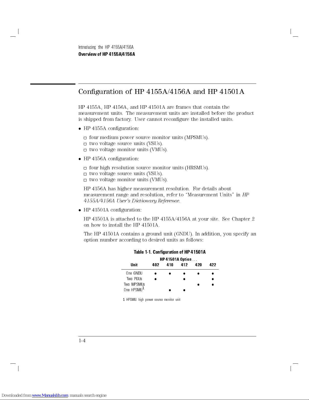
Conguration of HP 4155A/4156A and HP 41501A
HP 4155A, HP 4156A, and HP 41501A are frames that contain the
measurement units. The measurement units are installed before the product
is shipped from factory. User cannot recongure the installed units.
HP 4155A conguration:
four medium power source monitor units (MPSMUs).
two voltage source units (VSUs).
two voltage monitor units (VMUs).
HP 4156A conguration:
four high resolution source monitor units (HRSMUs).
two voltage source units (VSUs).
two voltage monitor units (VMUs).
HP 4156A has higher measurement resolution. For details about
measurement range and resolution, refer to \Measurement Units" in
4155A/4156A User's Dictionary Reference
.
HP
HP 41501A conguration:
HP 41501A is attached to the HP 4155A/4156A at your site
on how to install the HP 41501A.
The HP 41501A contains a ground unit (GNDU). In addition, you specify an
option number according to desired units as follows:
Table 1-1. Conguration of HP 41501A
1-4
HP 41501A Option
Unit
One GNDU
Two PGUs
Two MPSMUs
One HPSMU
1
HPSMU: high power source monitor unit
402 410 412 420 422
1
...
. See Chapter 2
Page 24

Front View of HP 4155A/4156A
Introducing the HP 4155A/4156A
Overview of HP 4155A/4156A
Figure 1-1. Front View of HP 4155A/4156A
LINE switch.
Use the LINE switch to turn analyzer on and o.
Flexible disk drive (FDD).
Use 3.5 inch diskette to load or store the analyzer settings and measurement
data.
Keyboard connector.
You can use an IBM PC/AT compatible keyboard (HP C1405B) to operate
the HP 4155A/4156A. See \Softkey Maps and External K
4155A/4156A User's Dictionary Reference
.
eyboard" in
HP
1-5
Page 25

Introducing the HP 4155A/4156A
Overview of HP 4155A/4156A
PAGE CONTROL key group.
Page Control keys are used to change the pages.
4
Chan
4
Meas
4
Display
5
5
5
Moves to CHANNELS page group.You dene channels, user
functions, and user variables.
Moves to MEASURE page group.You set the output parameters,
measurement parameters, and so on.
Moves to DISPLAY page group.You set the result display
format, auto analysis denitions, and so on.
4
Graph/List
4
Stress
4
System
MARKER/CURSOR key group.
Rotary knob and arrow keys of the Marker/Cursor key group are used to
move the marker and cursor.
Rotary knob Moves the marker, or increases or decreases setup value.
4(5,4)5
4*5
4
Fast
5
, and
5
5
Moves to GRAPH/LIST page group. This softkey toggles between
GRAPH and LIST pages.
Moves to STRESS page group.You dene the stress channels,
set the stress parameters, and monitor the stress forcing.
5
Moves to SYSTEM page group.You operate on diskette les,
set up plotting and printing environment, dene colors of the
display, and so on.
,
Moves eld pointer or cursor.
4+5
Moves the marker or cursor faster. When you rotate the rotary
knob or press the arrow keys with holding
marker or cursor moves faster.
4
5
key down, the
Fast
1-6
Page 26
Introducing the HP 4155A/4156A
Overview of HP 4155A/4156A
MEASUREMENT key group.
Measurement keys control the measurement, stress, and integration time.
4
Single
4
Repeat
4
Append
4
Stop
5
5
5
5
Executes the measurement once, then returns to the idle state
(or standby state if standby is enabled for the channel) after the
measurement is nished. Measurement data is updated, so data
of previous measurement is lost. Pressing the green key, then
4
5
key starts
Single
Starts and repeats the measurement continuously. Measurement
data is updated, so data of previous measurement is lost. To
stop the measurement, press
Executes the measurement once, then returns to idle state
(or standby state if standby is enabled for the channel) after
measurement is nished. Measurement data is appended to data
of previous measurement.
Stops the measurement or stress. Standby enabled channels
return to standby state, and other channels return to idle state.
knob sweep
measurement.
4
5
key.
Stop
4
4
4
4
and
MEASUREMENT indicator.
This indicator lights when HP 4155A/4156A is in the measurement state.
HIGH VOLTAGE indicator.
This indicator lights when a unit forces more than 40 V
Standby indicator.
This indicator lights when the HP 4155A/4156A is standby enabled, which
means that the channels that are standby enabled (
the standby state after the measurement is nished.
Standby
5
Stress
5
Short
Medium
4
Long
5
,
5
Toggles between the standby enabled (Standby indicator is lit)
and disabled states. If Standby indicator is lit, then
channels change to standby state (instead of idle state) when
measurement or stress nishes.
standby state.
Forces the specied stress. The guide around this key prevents
you from accidently pressing the
Sets the integration time to SHORT, MEDIUM, or LONG,
,
respectively.
5
4
5
key has no aect on
Stop
4
5
key.
Stress
.
STBY ON
) will return to
STBY ON
1-7
Page 27

Introducing the HP 4155A/4156A
Overview of HP 4155A/4156A
IBASIC key group.
IBASIC keys control the IBASIC program execution.
4
5
Run
4
5
Pause
4
5
Display
Run indicator.
When an IBASIC program is running, this indicator lights.
ENTRY key group.
You enter or modify data such as output values, comments, and variable
names.
Character keys Are used to enter alphanumeric and special characters.
4
5
Enter
Starts the IBASIC program that is in memory. The indicator is
on during program execution.
Pauses the IBASIC program execution.
Toggles between the IBASIC screen and measurement screen.
After you enter desired characters into the data entry
eld, press this key. The characters are entered at the
eld pointer location.
Also, you can use the green key to calculate the value of
the data entry eld. For example, if you press
greenkey
4
5
, the result (24) appears.
Enter
4
454*546
5
Blue key Changes entry mode to blue-key shift mode, and lights
the indicator. In this mode, you can enter the blue
characters that are printed above the keys. Pressing blue
key again changes to normal mode. Indicator turns o.
Green key Changes entry mode to green-key shift mode. This mode
is eective for the next pressed key, then changes back to
normal mode.
Edit keys Are used to edit the characters in the data entry eld.
User File keys Are used to operate quickly on a diskette le. Pressing
4
5
moves into the ler's SAVE function, and pressing
Save
4
5
moves into the ler's GET function.
Get
4
5
key.
Help
Pressing
4
Plot/Print
Pressing
your plotter, printer, or diskette le. If you press green key and
the screen image is dumped to plotter, printer, or diskette le.
1-8
4
5
Help
5
key.
4
Plot/Print
displays the
5
prints the setup information and measurement results to
help
pages.
4
Plot/Print
5
,
Page 28
Rear View of HP 4155A/4156A
Introducing the HP 4155A/4156A
Overview of HP 4155A/4156A
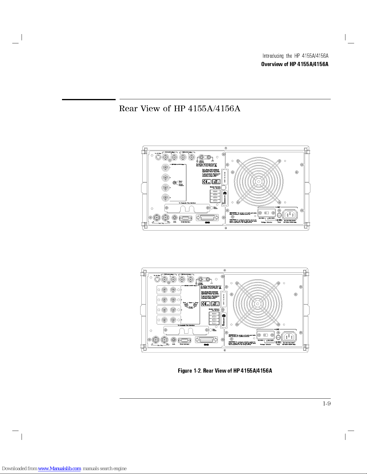
Figure 1-2. Rear View of HP 4155A/4156A
1-9
Page 29

Introducing the HP 4155A/4156A
Overview of HP 4155A/4156A
To R-Box terminal.
\To R-Box" terminal is a 10-pin connector.To use R-Box, connect this
terminal to control terminal of HP 16441A R-Box.
VSU terminals.
VSU output terminals are BNC connectors.To use VSUs, connect these
terminals to VSU terminals of HP 16442A or connector plate.
VMU terminals.
VMU input terminals are BNC connectors.To use VMUs, connect these
terminals to VMU terminals of HP 16442A or connector plate.
L
WARNING
L
Circuit Common ( ) and Frame ground ( ) terminals.
For oating measurement, remove the shorting bar (HP part number
5000-4206).
6
Do not oat the Circuit Common terminal at voltages greater than
referenced to frame ground. Failure to heed this warning may result in
damage to HP 4155A/4156A.
Serial number.
You need this
(HP HelpLine).
Voltage selector.
Voltage selector must be in proper position. Line voltage and position are:
Line Voltage Position
90|132 Vac left
198|264 Vac right
Fuse.
Use the following fuse:
Line Fuse type HP part number
100/120 Vac UL/CSA T 8A, 250 Vac 2110-0383
220/240 Vac UL/CSA T 4A, 250 Vac 2110-0014
serial number
when using the telephone assistance program
42 V
LINE input receptacle.
AC power cable is connected to this receptacle.
1-10
Page 30
Introducing the HP 4155A/4156A
Overview of HP 4155A/4156A
SMU terminals.
HP 4155A has four triaxial connectors. HP 4156A has eight triaxial
connectors, and you can use Kelvin connections. When you use HP 16442A
test xture and Kelvin connections, up tp 3 SMUs can be connected to HP
16442A test xture.
To Expander Box Interface.
When you use HP 41501A, you insert the board for HP 41501A into this
interface.
Zero Check terminal.
Ground reference point of the HP 4155A/4156A.
Ext Trig terminals.
Two BNC connectors: one for trigger input, and one for trigger output.
L
WARNING
Intlk terminal.
Used in conjunction with interlock function of HP 4155A/4156A. If the Intlk
6
terminal is open, maximum SMU output is limited to
connect this terminal to HP 16442A test xture or connector plate before
performing measurement. If you use connector plate, you must install
interlock circuit. For details on how to install the interlock circuit, see \T
Connect Interlock Terminal" in Chapter 2.
Dangerous voltage of up to the maximum voltage of SMUs may be present
at force, guard, and sense terminals if the interlock terminal is shorted.
Serial Interface connector.
9-pin female connector for RS-232-C serial communication.
HP-IB connector.
Use HP 10833A/B/C/D HP-IB cable.
40 V. Be sure to
o
1-11
Page 31

Introducing the HP 4155A/4156A
Overview of HP 4155A/4156A
Front and Rear View of HP 41501A
LINE switch.
Use the LINE switch to turn HP 41501A on and o.
41501A before turning on the HP 4155A/4156A.
1-12
Figure 1-3. Front and Rear View of HP 41501A
You must turn on the HP
Page 32

Introducing the HP 4155A/4156A
Overview of HP 4155A/4156A
L
Fuse.
Use the following fuse:
Line Fuse type HP part number
100/120 Vac UL/CSA T 8A, 250 Vac 2110-0383
220/240 Vac UL/CSA T 4A, 250 Vac 2110-0014
Voltage Selector.
Voltage selector must be in proper position. Line voltage and position are:
Line Voltage Position
90|132 Vac left
198|264 Vac right
LINE input receptacle.
AC power cable is connected to this receptacle.
Serial number.
The HP 41501A has its own serial number.You need this
when using the telephone assistance program (HP HelpLine).
GNDU connector.
The GNDU connector is a triaxial connector: inner conductor is sense
conductor is force, and outer conductor is circuit common.
serial number
, middle
1-13
Page 33

Introducing the HP 4155A/4156A
Overview of HP 4155A/4156A
Option 402
HP 41501A Option 402 has two PGUs.
Figure 1-4. Rear View of HP 41501A Option 402
PGU output terminals.
BNC connectors. Inner conductor is force and outer conductor is circuit
common.
Ext Pulse Generator Trig Out terminal.
Trigger pulses synchronized with PGU pulses are output. This trigger is
used to synchronize the PGU pulse outputs with external pulse generators
You
cannot
trigger, see \Measurement Functions" in
Reference
change the parameters of this trigger.For details about PGU
HP 4155A/4156A User's Dictionary
.
.
To SMU/Pulse Generator Selector Interface.
D-SUB 15-pin connector is used to control the HP 16440A SMU/pulse
generator selector.
1-14
Page 34

Introducing the HP 4155A/4156A
Overview of HP 4155A/4156A
Option 410
HP 41501A Option 410 has one HPSMU.
Figure 1-5. Rear View of HP 41501A Option 410
HPSMU terminals.
There are two triaxial connectors for Kelvin connections: one is for force and
the other is for sense.
1-15
Page 35
Introducing the HP 4155A/4156A
Overview of HP 4155A/4156A
Option 412
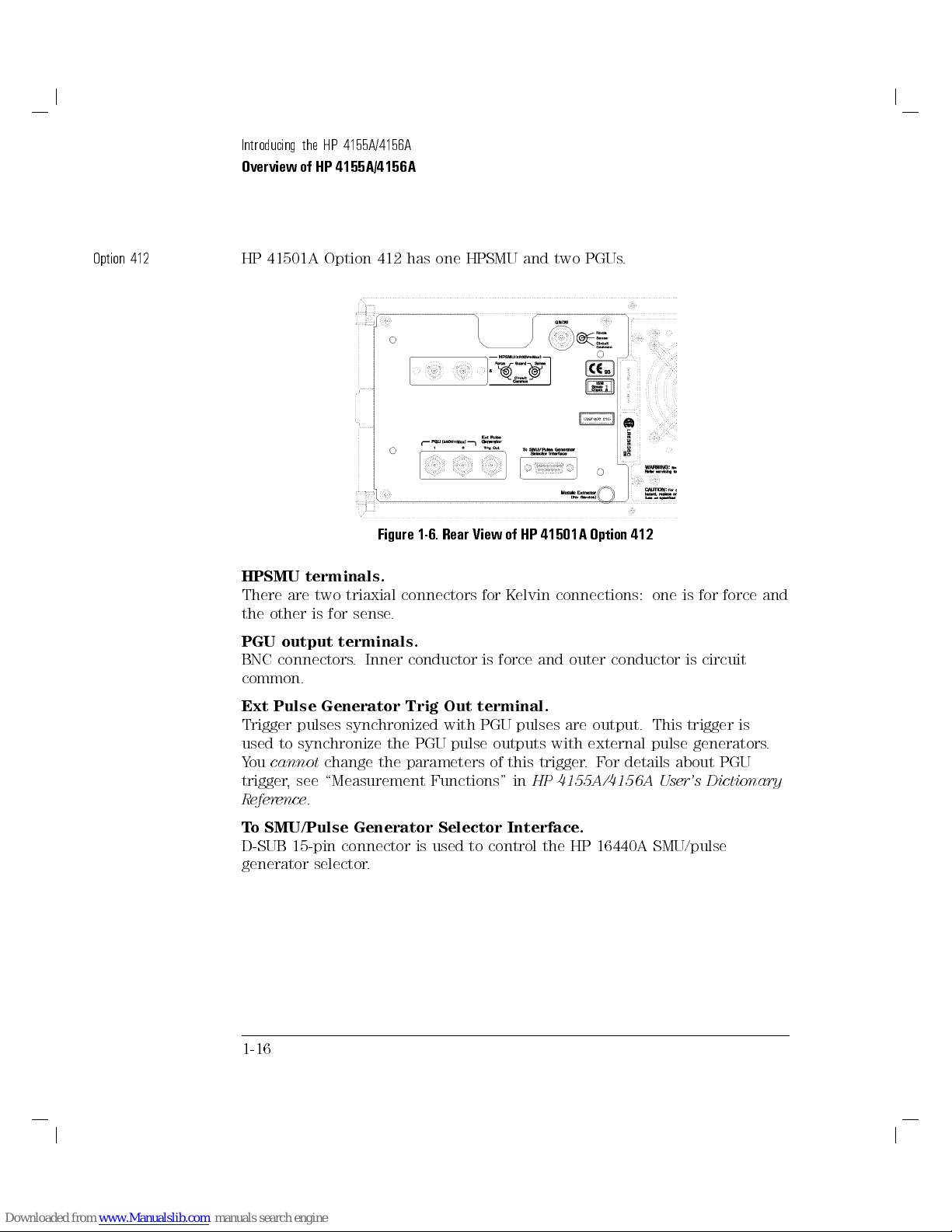
HP 41501A Option 412 has one HPSMU and two PGUs.
Figure 1-6. Rear View of HP 41501A Option 412
HPSMU terminals.
There are two triaxial connectors for Kelvin connections: one is for force and
the other is for sense.
PGU output terminals.
BNC connectors. Inner conductor is force and outer conductor is circuit
common.
Ext Pulse Generator Trig Out terminal.
Trigger pulses synchronized with PGU pulses are output. This trigger is
used to synchronize the PGU pulse outputs with external pulse generators
You
cannot
trigger, see \Measurement Functions" in
Reference
change the parameters of this trigger.For details about PGU
HP 4155A/4156A User's Dictionary
.
.
To SMU/Pulse Generator Selector Interface.
D-SUB 15-pin connector is used to control the HP 16440A SMU/pulse
generator selector.
1-16
Page 36

Introducing the HP 4155A/4156A
Overview of HP 4155A/4156A
Option 420
HP 41501A Option 420 has two MPSMUs.
Figure 1-7. Rear View of HP 41501A Option 420
MPSMU terminals.
Two MPSMUs are installed and each MPSMU has a triaxial connector
these connectors are not designed for Kelvin connections.
. But
1-17
Page 37
Introducing the HP 4155A/4156A
Overview of HP 4155A/4156A
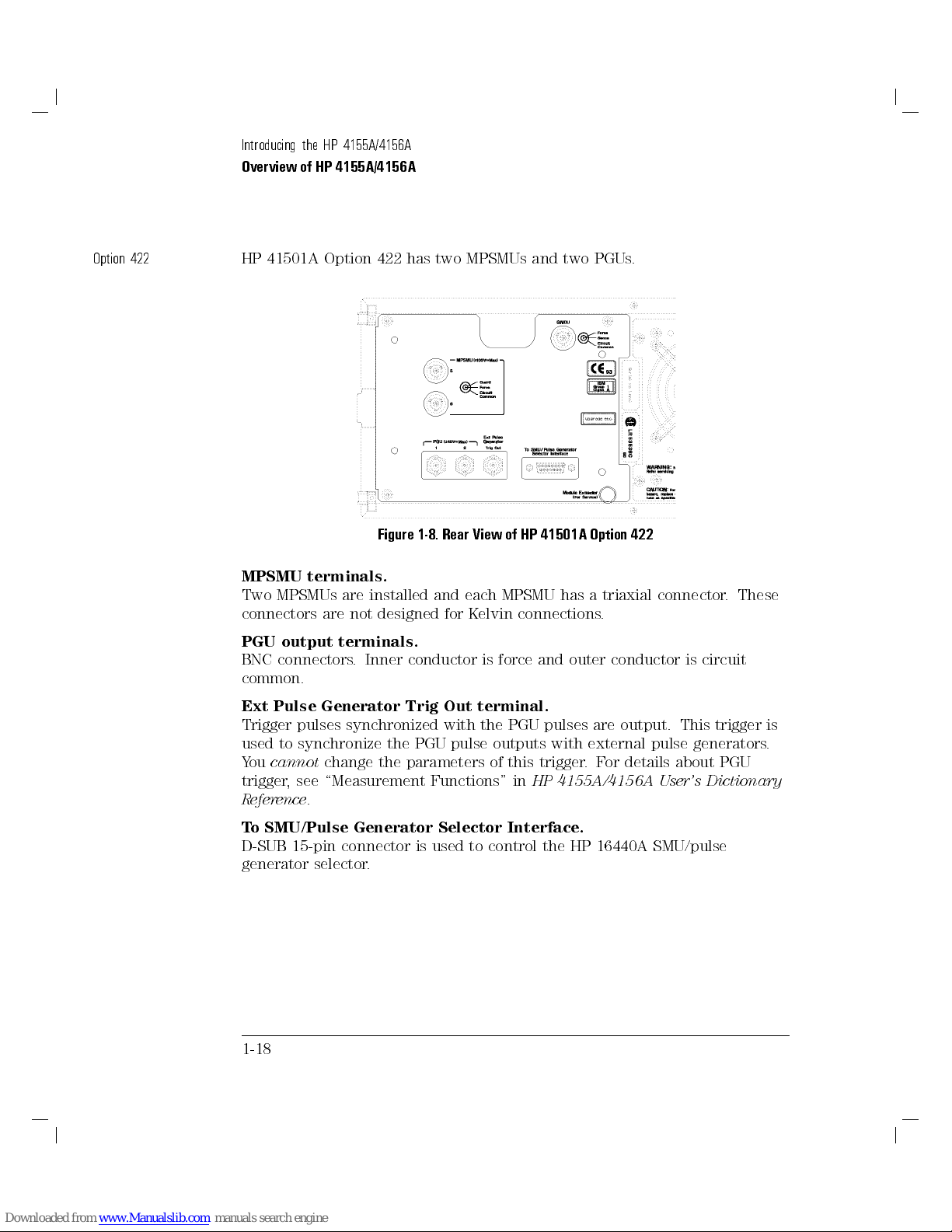
Option 422
HP 41501A Option 422 has two MPSMUs and two PGUs.
Figure 1-8. Rear View of HP 41501A Option 422
MPSMU terminals.
Two MPSMUs are installed and each MPSMU has a triaxial connector
connectors are not designed for Kelvin connections.
PGU output terminals.
BNC connectors. Inner conductor is force and outer conductor is circuit
common.
Ext Pulse Generator Trig Out terminal.
Trigger pulses synchronized with the PGU pulses are output. This trigger is
used to synchronize the PGU pulse outputs with external pulse generators
You
cannot
trigger, see \Measurement Functions" in
Reference
change the parameters of this trigger.For details about PGU
HP 4155A/4156A User's Dictionary
.
. These
.
To SMU/Pulse Generator Selector Interface.
D-SUB 15-pin connector is used to control the HP 16440A SMU/pulse
generator selector.
1-18
Page 38
An Overview of Functions
HP 4155A/4156A has the following useful functions.
Operation and control
Measurements and results display
Graphical analysis
Data storage
Plotting and printing
1-19
Page 39

Introducing the HP 4155A/4156A
An Overview of Functions
Operation and Control
You operate HP 4155A/4156A from the front-panel keys. Also, you can attach
a keyboard (HP C1405B) to HP 4155A/4156A, and operate it from keyboard.
See \Softkey Map and External Keyboard" in
Dictionary Reference
.
HP 4155A/4156A User's
HP 4155A/4156A is operated by a \form ll-in" method. That is
user-interface consists of setup and results pages, and you ll in elds
on appropriate pages to select a measurement mode, set measurement
parameters and conditions, set results display mode, and so on. After you
execute the measurement, measurement results are displayed on result pages.
When you operate from the front panel, the basic page ow is as follows:
1. channel denition
2. source setup
3. display setup
4. results display
Also, HP 4155A/4156A can be controlled via HP-IB by external controller,
such as an HP 9000 computer.To control HP 4155A/4156A, you create a
control (measurement) program by using a programming language such as HP
BASIC. The measurement program uses remote control commands of the HP
4155A/4156A. These are easy-to-understand commands based on Standard
Commands for Programmable Instruments (SCPI).
1-20
, the
Page 40
Introducing the HP 4155A/4156A
An Overview of Functions
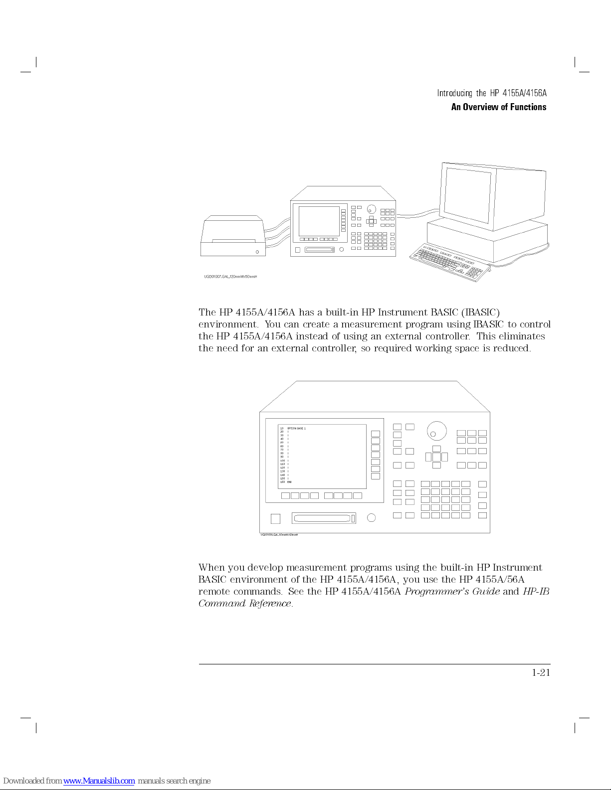
The HP 4155A/4156A has a built-in HP Instrument B
environment. You can create a measurement program using IBASIC to control
the HP 4155A/4156A instead of using an external controller
the need for an external controller, so required working space is reduced.
When you develop measurement programs using the built-in HP Instrument
BASIC environment of the HP 4155A/4156A, you use the HP 4155A/56A
remote commands. See the HP 4155A/4156A
Command Reference
.
Programmer's Guide
ASIC (IBASIC)
. This eliminates
and
HP-IB
1-21
Page 41

Introducing the HP 4155A/4156A
An Overview of Functions
Measurements and Results Display
You set up the elds on the setup pages of HP 4155A/4156A, then perform
the measurement. After measurement, you can display the measurement
results on the GRAPHICS or LIST page.
Measurement.
The HP 4155A/4156A can perform two types of measurements: sweep
measurement and sampling measurement. These two types of measurements
cannot
be executed at the same time.
Sweep measurement
For sweep measurements, an SMU or a VSU can become a primary sweep
source, secondary sweep source, synchronous sweep source, or constant
source.
For example, you can perform sweep measurements to get an Ic-Vce curve
of a bipolar transistor as in the following example:
In the example above, a primary source (Vce) and a secondary source
(Ib) are dened. After primary sweep source nishes each sweep, the
secondary sweep source outputs the next value.
1-22
Page 42

Introducing the HP 4155A/4156A
An Overview of Functions
Sampling measurements
For sampling measurements, the source units output constant values, and
measurements are executed by each unit at the specied intervals.
For example, you can get an integration curve of an RC integrator by
sampling measurement as follows:
In the example above, measurements by the monitor unit start when the
source unit outputs the specied value.
1-23
Page 43

Introducing the HP 4155A/4156A
An Overview of Functions
Setup pages.
You set the measurement mode, parameters, and conditions by lling in the
blank elds on the appropriate pages.You can enter variable names for the
output and measurement values, and you can dene more complex variables
called user functions.For example, you can specify a variable name for the
forward current, such as \If", and refer to this variable on other pages
instead of the unit name.
Results display.
You can display measurement results on the screen in graphics or list style.
When measurement starts, the results page appears according to the display
setting information that you set. Of course, the HP 4155A/4156A plots or
displays the results as the measurement progresses
the measurement parameters and conditions on the results page without
returning to the setup page.
Knob sweep.
For knob sweep measurement, you can vary the sweep range by rotating
the rotary knob. The knob sweep function is useful when you need to
quickly make a rough measurement of your DUT characteristics
need to dene the channel assignments, then you can start the knob sweep
measurement. You can also change parameters and conditions by using
secondary softkeys on the knob sweep page, and you can easily copy these
changes so that they will be used in the normal sweep mode
.You can also modify
.You only
.
Stress.
HP 4155A/4156A can force stress to your DUT for a specied duration. Y
can set the stress force parameters and channels independently from the
measurement channels. And the stress duration is controlled accurately.
You can force dc stress, and also ac stress because the HP 41501A can be
equipped with pulse generators.You can perform reliability evaluations by
repeating the stress-measurement cycle.
1-24
ou
Page 44

Introducing the HP 4155A/4156A
An Overview of Functions
Graphical Analysis
You can analyze the measurement results graphically by using a marker and
two lines. The marker can move on the measurement curve only, so you can
read the measurement values by reading the marker coordinates.You can
draw up to two lines on plotting area by following methods:
Normal line: through two points that are specied by cursors.
Gradient line: through one point specied by cursor with specied
gradient.
Tangent line: tangent to point specied by marker on measurement
curve.
Regression line: regression line for area specied by two cursors.
X/Y intercept values and gradient of each line are automatically displayed, so
you can get values such as threshold voltage (Vth) and Early voltage (VA).
Also, you can setup the auto-analysis page to position marker and lines at
desired location automatically after measurement nishes.For example, you
can automatically nd threshold voltage (Vth) as follows:
1.
Vg versus
2.
Maximum
onpId
3. Tangent is drawn to marker onpId
4. X intercept value of this tangent is Vth.
p
Id
@
@V g
curve.
curve, and Vg versus
p
Id
is found, and marker is moved to corresponding point
@
@V g
curve.
p
curve are drawn.
Id
1-25
Page 45
Introducing the HP 4155A/4156A
An Overview of Functions
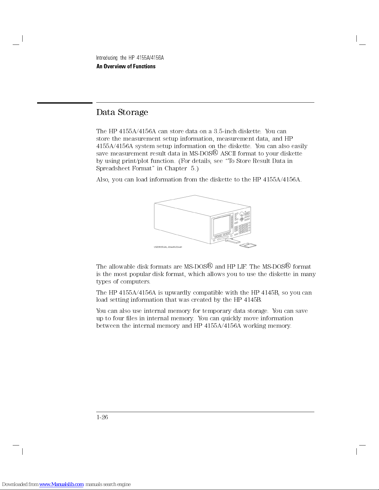
Data Storage
The HP 4155A/4156A can store data on a 3.5-inch diskette.You can
store the measurement setup information, measurement data, and HP
4155A/4156A system setup information on the diskette.You can also easily
save measurement result data in MS-DOS
by using print/plot function. (For details, see \To Store Result Data in
Spreadsheet Format" in Chapter 5.)
Also, you can load information from the diskette to the HP 4155A/4156A.
R
ASCII format to your diskette
R
The allowable disk formats are MS-DOS
is the most popular disk format, which allows you to use the diskette in many
types of computers.
The HP 4155A/4156A is upwardly compatible with the HP 4145B
load setting information that was created by the HP 4145B.
You can also use internal memory for temporary data storage.You can save
up to four les in internal memory.You can quickly move information
between the internal memory and HP 4155A/4156A working memory.
1-26
and HP LIF. The MS-DOS
R
format
, so you can
Page 46

Introducing the HP 4155A/4156A
An Overview of Functions
Plotting and Printing
You can print setup data, measurement results, and screen images on a
plotter or printer that is connected to the HP 4155A/4156A. Setup data and
list results are printed as a list report, and the graphics results page is plotted
as a graphics report. You can also plot or print the screen image.
You can connect your plotter or printer to the HP 4155A/4156A via serial
interface or HP-IB interface. See Chapter 2 for information about installing
your plotter or printer.
Also, you can store setup data, measurement results, and screen images on
diskette les. The stored data les can be read by other computers
So you can create reports that include measurement curves or data by using
spreadsheet software such as Lotus
software such as PageMakerTM.For details about saving data in MS-DOS
ASCII format, refer to \To Store Result Data in Spreadsheet Format" in
Chapter 5.
R
1-2-3
R
or by using desktop publishing
.
R
1-27
Page 47

Introducing the HP 4155A/4156A
An Overview of Functions
Page 48

2
Installation
Page 49

Installation
This chapter describes requirements to install HP 4155A/4156A and the tasks
for installation, and is organized into the following four sections:
Requirements
Setting up HP 4155A/4156A
Installing Accessories
L
WARNING
The HP 4155A/4156A can force dangerous voltages (200 V for HPSMU
and 100 V for HRSMU and MPSMU) at the force
terminals.To prevent electric shock hazard, the following safety
precautions must be observed during the use of the HP 4155A/4156A.
Use a three-conductor ac power cable to connect cabinet (if used) and
HP 4155A/4156A to an electric ground (safety ground).
If you do not use HP 16442A Test Fixture, make sure to connect the
INTLK terminal to a switch that turns o when the shielding box access
door is opened.
Conrm periodically that INTLK function works normally.
Before touching the connections of the force, guard, and sense
terminals, turn the HP 4155A/4156A o and discharge any capacitors
whenever possible. If you do not turn the HP 4155A/4156A o,
complete
settings.
Set the SMU output switches to o.
Conrm that HIGH VOLTAGE indicator is not lit.
Open the shielding box access door (open the INTLK terminal).
Discharge any capacitors if the capacitance is connected to an SMU
Warn workers around the HP 4155A/4156A about dangerous conditions.
all
of the following items, regardless of any HP 4155A/4156A
, guard, and sense
,
.
2-2
Page 50

Requirements
This section describes the following requirements
Power requirements
Power cable
Ventilation requirements
Operating environment
2-3
Page 51
Installation
Requirements
Power Requirements
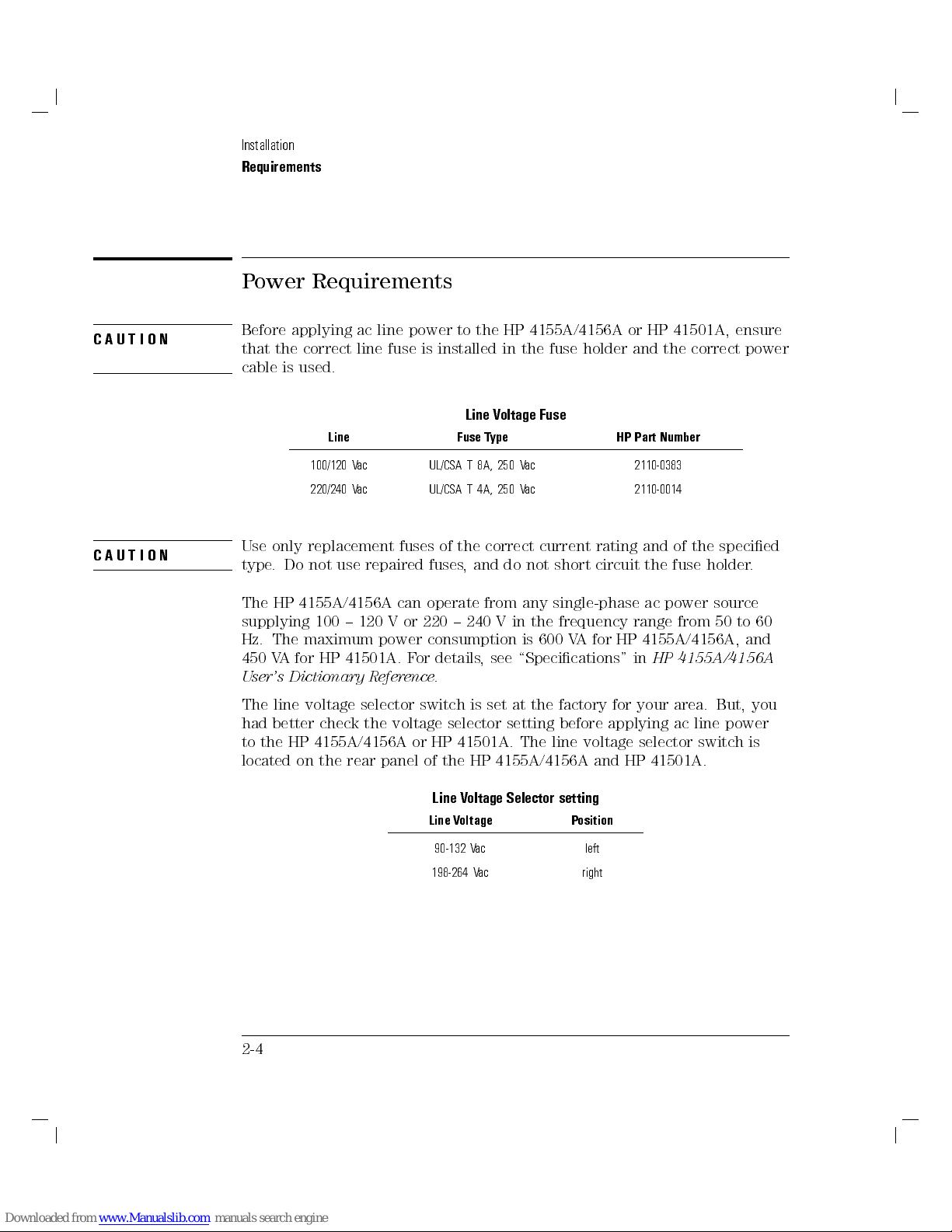
CAUTION
CAUTION
Before applying ac line power to the HP 4155A/4156A or HP 41501A, ensure
that the correct line fuse is installed in the fuse holder and the correct power
cable is used.
Line Voltage Fuse
Line Fuse Type HP Part Number
100/120 Vac UL/CSA T 8A, 250 V
220/240 Vac UL/CSA T 4A, 250 Vac 2110-0014
Use only replacement fuses of the correct current rating and of the specied
type. Do not use repaired fuses, and do not short circuit the fuse holder
The HP 4155A/4156A can operate from any single-phase ac power source
supplying 100 { 120 V or 220 { 240 V in the frequency range from 50 to 60
Hz. The maximum power consumption is 600 VA for HP 4155A/4156A, and
450 VA for HP 41501A. For details, see \Specications" in
User's Dictionary Reference
The line voltage selector switch is set at the factory for your area. But, you
had better check the voltage selector setting before applying ac line power
to the HP 4155A/4156A or HP 41501A. The line voltage selector switch is
located on the rear panel of the HP 4155A/4156A and HP 41501A.
.
ac 2110-0383
.
HP 4155A/4156A
2-4
Line Voltage Selector setting
Line Voltage Position
90-132 Vac left
198-264 Vac right
Page 52
Installation
Requirements
Power Cable
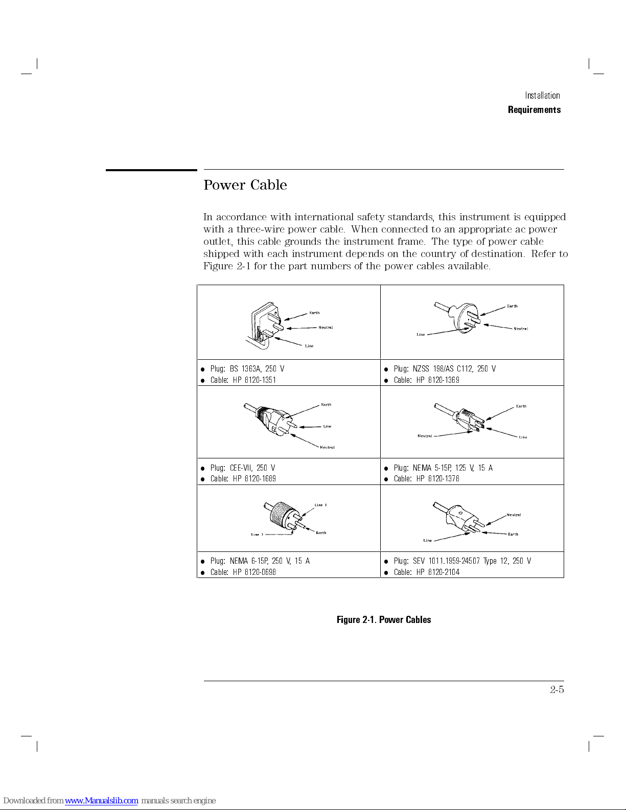
In accordance with international safety standards, this instrument is equipped
with a three-wire power cable. When connected to an appropriate ac power
outlet, this cable grounds the instrument frame. The type of power cable
shipped with each instrument depends on the country of destination. Refer to
Figure 2-1 for the part numbers of the power cables available.
Plug: BS 1363A, 250 V
Cable: HP 8120-1351
Plug: NZSS 198/AS C112, 250 V
Cable: HP 8120-1369
Plug: CEE-VII, 250 V
Cable: HP 8120-1689
Plug: NEMA 6-15P, 250 V,15A
Cable: HP 8120-0698
Plug: NEMA 5-15P, 125 V,15A
Cable: HP 8120-1378
Plug: SEV 1011.1959-24507 Type 12, 250 V
Cable: HP 8120-2104
Figure 2-1. Power Cables
2-5
Page 53

Installation
Requirements
Plug: DHCR 107, 220 V
Cable: HP 8120-2956
Plug: JIS C 8303, 125 V,15A
Cable: HP 8120-4753
Plug: SABS 164, 250 V
Cable: HP 8120-4211
WARNING
Power Cables (continued)
If the plug on the cable does not t the power outlet, or the cable is to be
attached to a terminal block, cut the cable at the plug end and re-wire it.
This work should be performed by a qualied electrician|all local electrical
codes being strictly observed.
The color coding used in the cable will depend on the cable supplied. If a
new plug is to be connected, it must meet local safety requirements and
include the following features:
Adequate load-carrying capacity (see table of \Specications" in
4155A/4156A User's Dictionary Reference
Ground connection.
Cable clamp.
For protection from electrical shock, the power cable ground must not be
defeated.
2-6
).
HP
Page 54

Installation
Requirements
Ventilation Requirements
The HP 4155A/4156A has one cooling fan, and HP 41501A has two cooling
fans.To ensure adequate airow, make sure that there is adequate clearance
around the cooling fans: 6 inches (150 mm) behind, 3 inches (70 mm) sides,
and 0.5 inch (12 mm) above and below.
If the airow is restricted, the internal operating temperature will be
higher, reducing the instrument's reliability or causing the instrument's
thermal-protection circuits to automatically switch o the instrument.
Operating Environment
The HP 4155A/4156A and HP 41501A must be operated within the following
environmental conditions:
Temperature: 5Cto40C (41F to 104F)
Humidity: 15% to 80% RH at 40C (104F)
Cleaning
To prevent electrical shock, never use a wet cloth when cleaning the
HP 4155A/4156A. Always use a slightly damp or dry cloth to clean HP
4155A/4156A.
2-7
Page 55

Setting up HP 4155A/4156A
This section describes what you do when you receive the HP 4155A/4156A
and accessories.
Briey, you must do the following:
1. Inspect HP 4155A/4156A and accessories.
2. Install HP 41501A with HP 4155A/4156A, if needed.
3. Check HP 4155A/4156A operation after supplying ac line power.
To satisfy the specications of HP 4155A/4156A and HP 41501A measurement
accuracy, perform calibration and adjustment every year.
To Inspect HP 4155A/4156A and Accessories
Inspect the following items when the HP 4155A/4156A and accessories arrive
at your site, and when you open the boxes that contain the HP 4155A/4156A
and accessories:
When the HP 4155A/4156A and accessories arrive at your site
unpacking any components, inspect all boxes for any signs of damage that
might have occurred during shipment such as:
Dents
Scratches
Cuts
Water marks
If you suspect damage, notify your local HP sales oce.
When you open the boxes that contain the HP 4155A/4156A and
accessories, check the components against the contents lists that are
attached to the boxes.
If anything is missing, notify your local HP sales oce.
2-8
, and before
Page 56

Setting up HP 4155A/4156A
To Install HP 41501A SMU/Pulse Generator Expander
1. Put the HP 41501A on your workbench. 2. Put the HP 4155A/4156A on the HP 41501A.
Installation
WARNING
3. Remove the blank panel labeled \To Expander Box
Interface" from the rear panel of the HP 4155A/4156A.
The HP 4155A/4156A together with the HP 41501A weighs about 40 kg
(88.4 lb). The HP 4155A/4156A is just placed on top of the HP 41501A
without attaching it securely.So, be very careful when handling.
4. Insert the interface board from the HP 41501A into the
HP 4155A/4156A, then attach it with the thumbscrews.
2-9
Page 57
Installation
Setting up HP 4155A/4156A
To Check HP 4155A/4156A Operation
1. Make sure that the line switches are set to o.
2. On the HP 4155A/4156A, make sure that the
is tied to frame ground terminal by shorting-bar. If not, a potential shock
hazard exists.
3. Connect the power cable between the HP 4155A/4156A and outlet at your
site. If the HP 41501A is also installed, connect the power cable between
the HP 41501A and the outlet.
4. If the HP 41501A is installed, press the LINE button to switch on.
5. Press the LINE button to switch on the HP 4155A/4156A. The initialization
screen appears on the CRT of the HP 4155A/4156A.
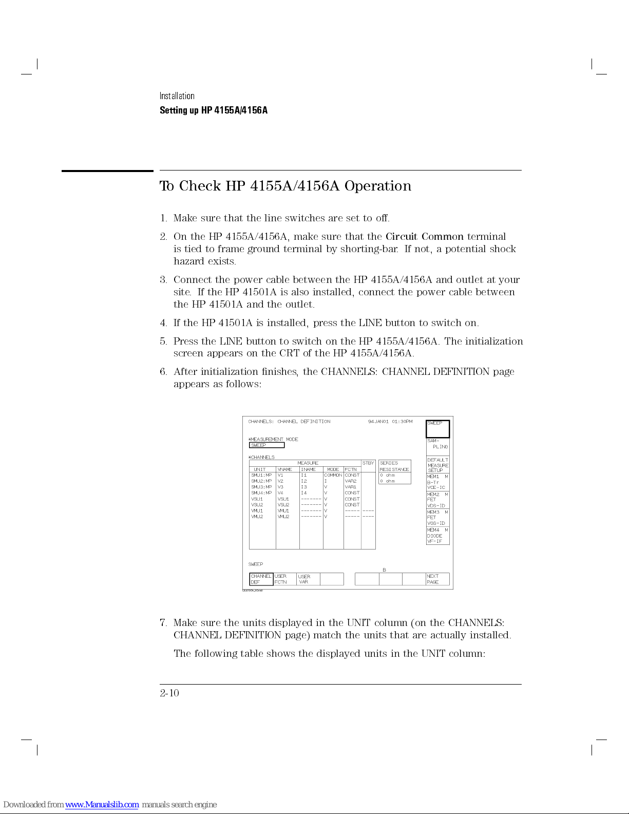
6. After initialization nishes, the CHANNELS: CHANNEL DEFINITION page
appears as follows:
Circuit Common
terminal
7. Make sure the units displayed in the UNIT column (on the CHANNELS:
CHANNEL DEFINITION page) match the units that are actually installed.
The following table shows the displayed units in the UNIT column:
2-10
Page 58

Setting up HP 4155A/4156A
HP 4155A HP 4156A HP 41501A
Installation
SMU1:MP
SMU2:MP
SMU3:MP
SMU4:MP
VSU1
VSU2
VMU1
VMU2
1
These are labeled on the rear panel of the HP 41501A.
8. If HP 41501A units are not displayed in UNIT column, turn o the HP
4155A/56A and HP 41501A, then make sure that interface board of
HP 41501A is rmly inserted into HP 4155A/56A. Turn on HP 41501A,
then turn on HP 4155A/56A.
9. Press
4
System
softkey. Conrm that POWER LINE FREQUENCY eld is correct frequency
for your site. If not, select the correct secondary softkey.
SMU1:HR
SMU2:HR
SMU3:HR
SMU4:HR
VSU1
VSU2
VMU1
VMU2
5
front-panel key, then select
HPSMU Installed1MPSMU Installed1PGU Installed
SMU5:HP SMU5:MP
GNDU
SMU6:MP
NNNNNNNNNNNNNNNNNNNNNNNNNNNNNNNNNNNNNNNN
N
MISCELLANEOUS
1
PGU1
PGU2
primary
If problems occur, see Chapter 6.
2-11
Page 59

Installing Accessories
This section describes how to install the HP 4155A/4156A and accessories at
your site. Refer to \Ventilation Requirements" when considering the proper
location at which to install the HP 4155A/4156A.
This section describes how:
To install connector plate
To connect interlock terminal
To install HP 16442A Test Fixture
To install HP 16441A R-Box
To install HP 16440A SMU/Pulse Generator Selector
To connect HP 16440A to HP 4155A/4156A
When you install a keyboard (HP C1405B), connect the connector of the
keyboard to the keyboard interface on the front-panel
HP 4155A/4156A. The HP 4155A/4156A recognizes the keyboard during the
power-on self-test.
before
switching on the
2-12
Page 60

Installation
Installing Accessories
To Install Connector Plate
1. Before installing connector plate, make sure that HP 4155A/4156A and
HP 41501A are turned o.
2. Create proper openings and screw holes on your shielding box that match
the size of connector plate. See Figure 2-2, Figure 2-3, or Figure 2-4 for
dimensions of the connector plates.
3. Attach the connector plates with screws, nuts, and washers.
4. To prevent electric shock, make sure to install interlock circuit. (See \T
Connect Interlock Terminal".)
5. Connect the furnished cables between the HP 4155A/4156A and connector
plates.
For details about connections between HP 4155A/4156A and the terminals
on the connector plates, refer to \To Install HP 16442A Test Fixture"in
this chapter. Connections to connector plate are similar to connections to
test xture.
The proper connector plates are furnished with HP 4155A, HP 4156A, and
HP 41501A.
The screws, nuts, and washers are not furnished. Each connector plate has
four screw holes (3.0 mm in diameter).
o
2-13
Page 61

Installation
Installing Accessories
If you do not use the HP 16442 test xture (for example, you use a wafer
prober or your own test xture), you need to perform measurements in a
shielding box because of the following:
To prevent the operator from receiving an electric shock from the output
voltage or current of the HP 4155A/4156A.
To minimize the eects of environmental noise and ambient light.
For details on how to connect terminals of connector plate and DUTs, refer to
\Connection to Device Under Test (DUT)" in Chapter 3.
2-14
Figure 2-2.
Dimensions of Connector Plate for HP 4155A
(HP Part Number: 04155-60006)
Page 62

Table 2-1. Connectors on Connector Plate
Connector HP Part Number
Triaxial 1250-1906
for SMU, GNDU
Coaxial (BNC) 1250-0083
for VSU, VMU, PGU
Interlock 1252-1419
Installation
Installing Accessories
Figure 2-3.
Dimensions of Connector Plate for HP 4156A
(HP Part Number: 04156-60002)
2-15
Page 63

Installation
Installing Accessories
Figure 2-4.
Dimensions of Connector Plate for HP 41501A
(HP Part Number: 41501-60004)
2-16
Page 64
Installation
Installing Accessories
To Connect Interlock Terminal
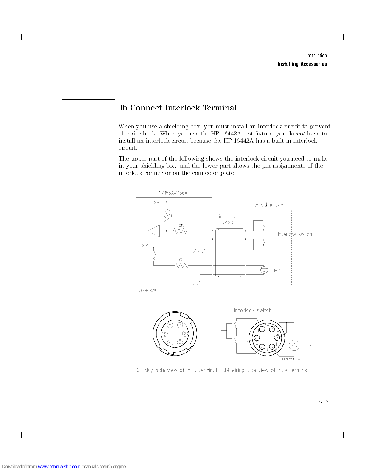
When you use a shielding box, you must install an interlock circuit to prevent
electric shock. When you use the HP 16442A test xture, you do
install an interlock circuit because the HP 16442A has a built-in interlock
circuit.
The upper part of the following shows the interlock circuit you need to make
in your shielding box, and the lower part shows the pin assignments of the
interlock connector on the connector plate.
not
have to
2-17
Page 65
Installation
Installing Accessories
interlock (Intlk) terminal.
To prevent an operator from receiving an electric shock from high voltage
(more than640 V), you connect the interlock (Intlk) terminal (of the
connector plate) to a switch that turns on when the shielding box door is
closed, and that turns o when the shielding box access door is opened. For
safety, use two switches in series.
If the door is open (the interlock terminals are open), the SMU cannot force
more than640 V. If the door is opened while the SMU output is more than
6
40 V, the HP 4155A/4156A immediately drops the outputs of all units to 0 V.
Conversely, if the door is closed (interlock terminals are shorted), this
function is disabled. So, you can force more than640 V.
WARNING
Dangerous voltages of up to the maximum voltage of SMUs may be
present at force, guard, and sense terminals when the interlock terminals
are shorted.
HP 16435A Interlock Cable Adapter.
If you already have a connector plate or test xture that has a BNC coaxial
connector for interlock (such as the HP 16088B test xture), you can use HP
16435A Interlock Cable Adapter to connect the test xture.
To connect:
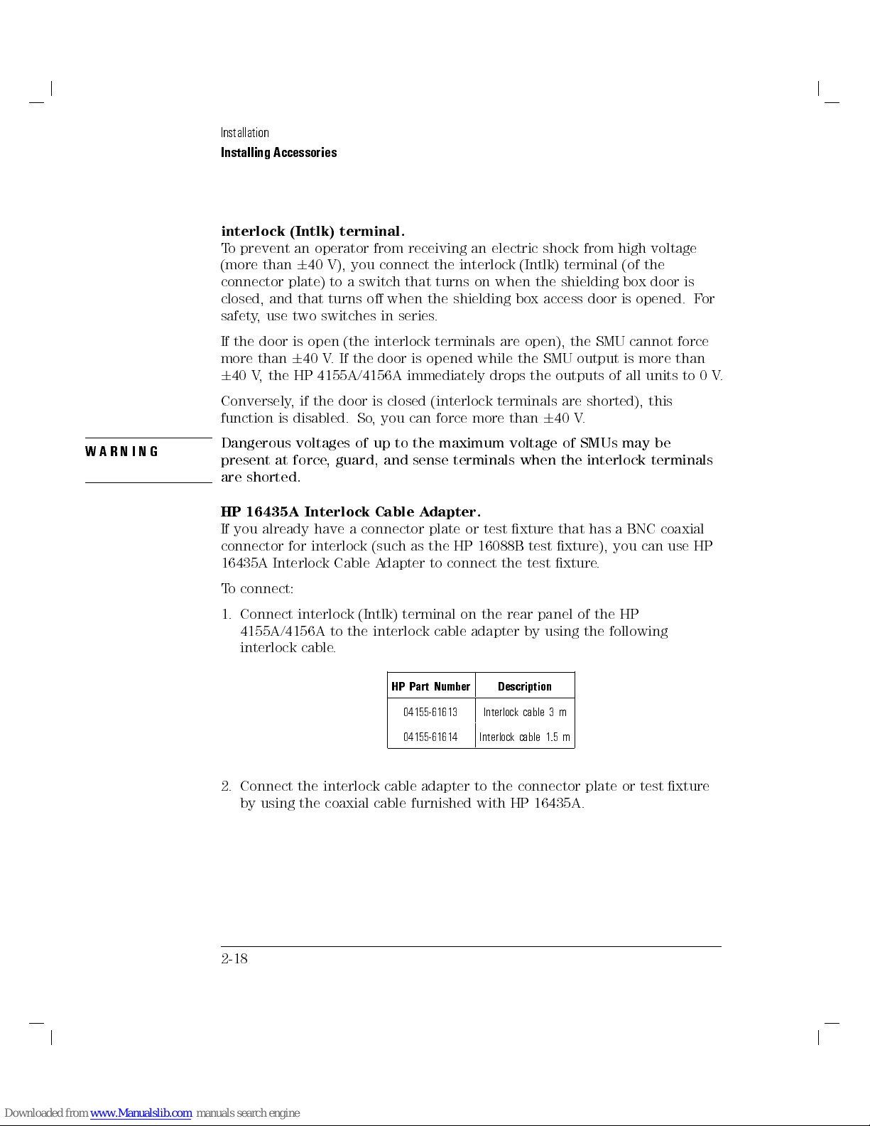
1. Connect interlock (Intlk) terminal on the rear panel of the HP
4155A/4156A to the interlock cable adapter by using the following
interlock cable.
HP Part Number Description
04155-61613 Interlock cable 3 m
04155-61614 Interlock cable 1.5 m
2. Connect the interlock cable adapter to the connector plate or test xture
by using the coaxial cable furnished with HP 16435A.
2-18
Page 66

Installation
Installing Accessories
Warning Indicator on HP 16088B Test Fixture
The high voltage warning indicator on this test xture is designed only for HP 41423A High Voltage
Source/Monitor Unit for HP 4142B.
This warning indicator is not valid when you use the HP 16088B test xture with the HP
4155A/4156A by using HP 16435A interlock cable adapter.
LED terminal.
When more than640 V is forced from an SMU, the LED lights to indicate
high voltage output
recommended parts.
You can get the following parts from Hewlett-Packard:
.
HP Part Number Description
3101-3241 switch
3101-0302 switch
1450-0641 LED (V
2.1 V @ IF= 10 mA)
=
F
2-19
Page 67

Installation
Installing Accessories
Figure 2-5. Dimensions of Interlock Switch (HP part number 3101-0302)
Figure 2-6. Dimensions of Interlock Switch (HP part number 3101-3241)
2-20
Page 68

Figure 2-7. Dimensions of LED (HP part number 1450-0641)
ToPerform Interlock Circuit Test
To conrm that interlock circuit test, do as follows:
Installation
Installing Accessories
1. Connect the
2.
Press
SYSTEM: SELF-CALIBRATION/DIAGNOSTICS page.
3.
In the CALIB/DIAG eld, select
4.
In the CATEGORY eld, select
5. Move pointer to the
6.
Select
7. Conrm the following:
LED turns on within 1 sec from when interlock circuit is shorted.
LED turns o within 1 sec from when interlock circuit is open.
8.
To stop the interlock test, select
Intlk
4
5
System
NNNNNNNNNNNNNNNNNNNNNN
N
EXECUTE
terminal of HP 4155A/4156A to your interlock circuit.
front-panel key, then select
NNNNNNNNNNNNNN
DIAG
NNNNNNNNNNNNNNNNNNNNNNNNNNNNNNNNNNNNNN
I/O & PERIPH
403 (INT.) Interlock & LED
secondary softkey.
NNNNNNNNNNNNN
N
STOP
NNNNNNNNNNNNNNNNNNNNNNNNNNNNNNNN
CALIB/DIAG
secondary softkey.
secondary softkey.
primary softkey to display the
secondary softkey.
eld.
2-21
Page 69
Installation
Installing Accessories
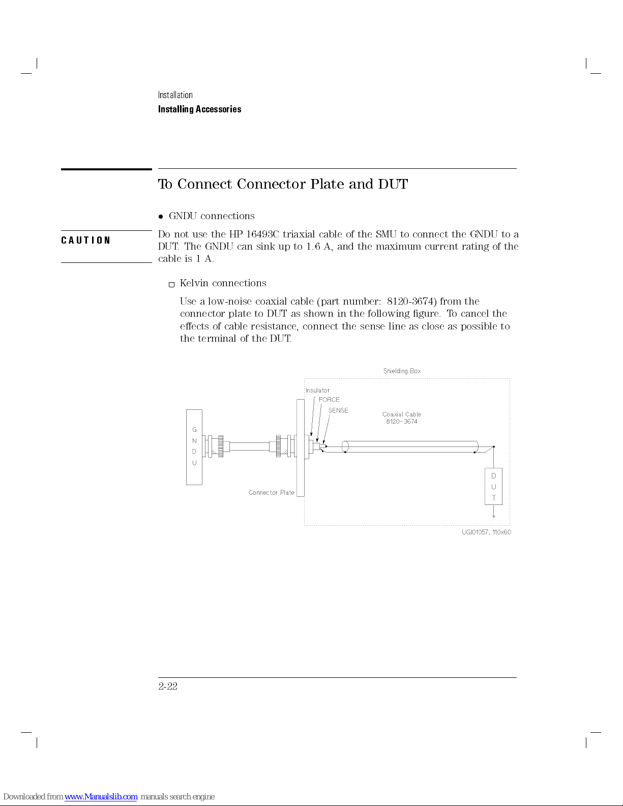
To Connect Connector Plate and DUT
GNDU connections
CAUTION
Do not use the HP 16493C triaxial cable of the SMU to connect the GNDU to a
DUT. The GNDU can sink up to 1.6 A, and the maximum current rating of the
cable is 1 A.
Kelvin connections
Use a low-noise coaxial cable (part number: 8120-3674) from the
connector plate to DUT as shown in the following gure
eects of cable resistance, connect the sense line as close as possible to
the terminal of the DUT.
.To cancel the
2-22
Page 70

Installation
Installing Accessories
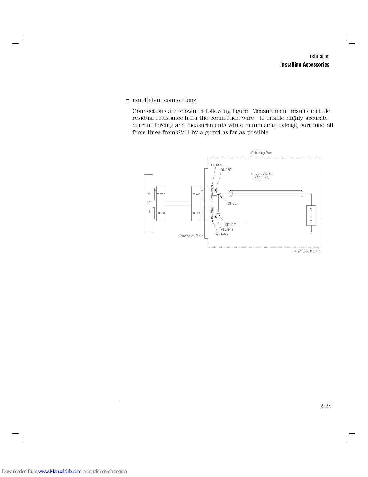
non-Kelvin connections
Short sense and force at the connector plate as shown. Use AWG
22 single-strand insulated wire (part number: 8150-2639) from the
connector plate to the DUT. Measurement results include the residual
resistance of the connection wire.
To easily connect GNDU for a measurement in which the accuracy is not
important, connect only force to the DUT, without shorting sense and
force.
2-23
Page 71

Installation
Installing Accessories
SMU connections
WARNING
CAUTION
The SMU forces dangerous voltages of up to6100 V (6200 V for HPSMU)
at the force, sense, and guard terminals.
To prevent electric shock, do not expose these lines.
Before turning the HP 4155A/4156A on, connect the Intlk terminal to a
switch that turns o when the shielding box access door is opened.
Before you touch connections of these terminals, turn HP 4155A/56A o,
disconnect power cable, and discharge any capacitors.
Never connect the guard terminal to any output, including circuit common,
chassis ground, or the guard terminal of any other unit. Doing so may result
in an emergency condition.
Kelvin connections
Use low-noise coaxial cable (part number: 8120-4461) from connector
plate to DUT as shown in following gure.To cancel eects of cable
resistance, connect sense line as close as possible to DUT terminal. T
prevent oscillations, do not use cables longer than 1.5 m. F
accurate current forcing and measurements while minimizing leakage,
surround all force and sense lines from SMU by a guard as far as
possible, and make cables stable by taping.
or highly
o
2-24
Page 72
Installation
Installing Accessories
non-Kelvin connections
Connections are shown in following gure. Measurement results include
residual resistance from the connection wire.To enable highly accurate
current forcing and measurements while minimizing leakage, surround all
force lines from SMU by a guard as far as possible.
2-25
Page 73
Installation
Installing Accessories
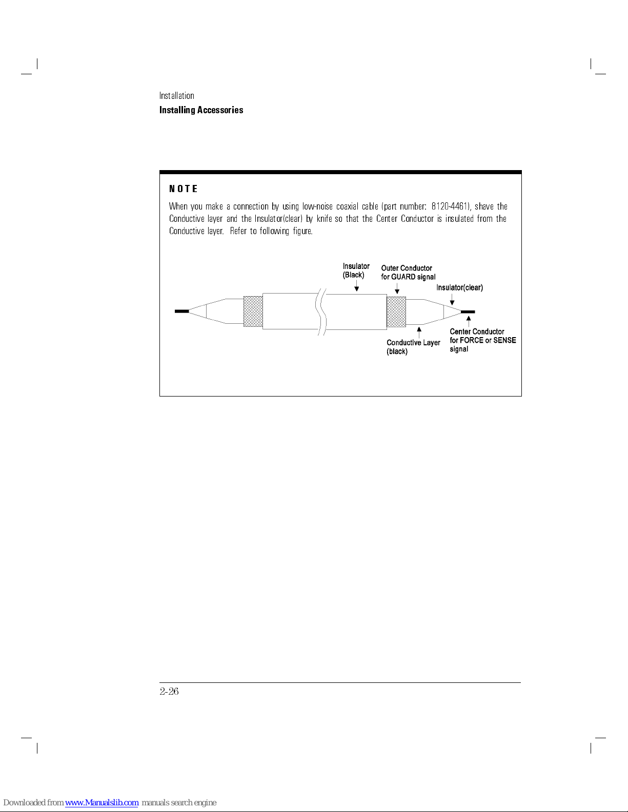
NOTE
When you make a connection by using low-noise coaxial cable (part number: 8120-4461), shave the
Conductive layer and the Insulator(clear) by knife so that the Center Conductor is insulated from the
Conductive layer. Refer to following gure.
2-26
Page 74

Installing Accessories
VSU and VMU connections
The following gure shows an example of a connection between VSU1,
VSU2, VMU1, or VMU2 and a DUT. Use AWG 24 single-strand insulated
wire (part number: 8150-0447) to connect the connector plate and the
DUT.
Installation
2-27
Page 75

Installation
Installing Accessories
PGU connections
Regardless of output impedance setting, use a low-noise coaxial cable (part
number: 8120-0102) from the connector plate to the DUT as shown in the
following gure. If you use HP 16440A selector, use a low-noise coaxial
cable (part number: 8120-4461).
2-28
Page 76

Installation
Installing Accessories
To Install HP 16442A Test Fixture
Before performing the following procedure, make sure that HP 4155A/4156A
and HP 41501A are turned o.
When you use HP 16442A test xture without HP 16441A R-Box or HP
16440A selector, you can make HP 16442A stable by using stabilizers as
shown in the following gure.
1. Put a stabilizer on both sides of test xture
2. Screw a athead screw into hole of each stabilizer.
.
2-29
Page 77

Installation
Installing Accessories
Connecting HP 4155A and HP 16442A test xture
WARNING
CAUTION
1. To prevent shock,
cable:
2. Connect the following by using 3.0 m or 1.5 m coaxial cables:
VSU
3. Connect the following by using 3.0 m or 1.5 m coaxial cables:
VMU
4. Connect the following by using 3.0 m or 1.5 m triaxial cables:
MPSMU
MPSMUs force dangerous voltage of up to6100 V at the Force, Sense, and
Guard terminals.To prevent electric shock, do not expose these lines.
Never connect Guard terminal to any output, including circuit common, frame
ground, or other guard terminal. Doing so will damage SMU.
2-30
Intlk
terminals (HP 4155A)
terminals (HP 4155A)
terminals (HP 4155A)
be sure
terminal (HP 4155A)
to connect following by 3.0m or 1.5m Intlk
()
()
()
()
Intlk
terminal (HP 16442A)
VSU
terminals (HP 16442A)
VMU
terminals (HP 16442A)
SMU
terminals (HP 16442A)
Page 78
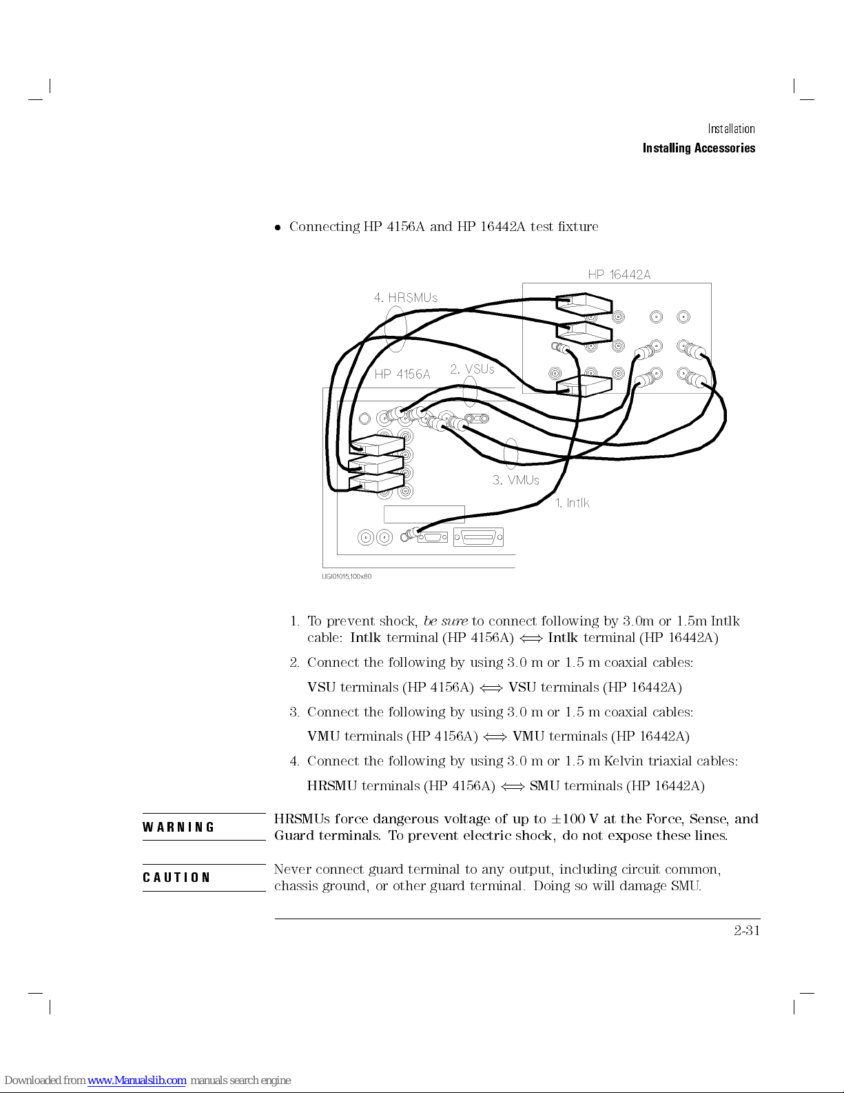
Connecting HP 4156A and HP 16442A test xture
Installation
Installing Accessories
WARNING
CAUTION
1. To prevent shock,
cable:
2. Connect the following by using 3.0 m or 1.5 m coaxial cables:
VSU
3. Connect the following by using 3.0 m or 1.5 m coaxial cables:
VMU
4. Connect the following by using 3.0 m or 1.5 m K
HRSMU
HRSMUs force dangerous voltage of up to6100 V at the Force, Sense, and
Guard terminals.To prevent electric shock, do not expose these lines.
Never connect guard terminal to any output, including circuit common,
chassis ground, or other guard terminal. Doing so will damage SMU.
Intlk
terminals (HP 4156A)
terminals (HP 4156A)
terminals (HP 4156A)
be sure
terminal (HP 4156A)
to connect following by 3.0m or 1.5m Intlk
()
()
()
()
Intlk
terminal (HP 16442A)
VSU
terminals (HP 16442A)
VMU
terminals (HP 16442A)
SMU
terminals (HP 16442A)
elvin triaxial cables:
2-31
Page 79

Installation
Installing Accessories
Connecting HP 41501A and HP 16442A test xture
1. To prevent electric shock, make sure that
4155A/4156A is connected to
2. Connect the following by using a 3.0 m or 1.5 m GNDU cable:
GNDU
3. If the HP 41501A is equipped with two PGUs
using 3.0 m or 1.5 m coaxial cables:
PGU
4. Do the following:
2-32
terminal (HP 41501A)
terminals (HP 41501A)
If the HP 41501A is equipped with two MPSMUs, connect the
following by using 3.0 m or 1.5 m triaxial cables:
MPSMU
If the HP 41501A is equipped with HPSMU, connect the following by
using 3.0 m or 1.5 m Kelvin triaxial cable:
HPSMU
terminals (HP 41501A)
terminal (HP 41501A)
Intlk
()
()
terminal of HP 16442A.
GNDU
PGU
()
()
Intlk
terminal of HP
terminal (HP 16442A)
, connect the following by
terminals (HP 16442A)
SMU
terminals (HP 16442A)
SMU
terminal (HP 16442A)
Page 80
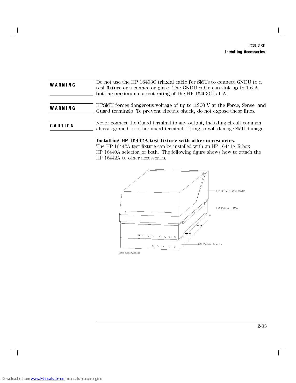
Installation
Installing Accessories
WARNING
WARNING
CAUTION
Do not use the HP 16493C triaxial cable for SMUs to connect GNDU to a
test xture or a connector plate. The GNDU cable can sink up to 1.6 A,
but the maximum current rating of the HP 16493C is 1 A.
HPSMU forces dangerous voltage of up to6200 V at the Force, Sense, and
Guard terminals.To prevent electric shock, do not expose these lines.
Never connect the Guard terminal to any output, including circuit common,
chassis ground, or other guard terminal. Doing so will damage SMU damage.
Installing HP 16442A test xture with other accessories.
The HP 16442A test xture can be installed with an HP 16441A R-box,
HP 16440A selector, or both. The following gure shows how to attach the
HP 16442A to other accessories.
2-33
Page 81

Installation
Installing Accessories
Installing HP 16088B Test Fixture
You can easily install HP 16088B test xture by using HP 16434A Kelvin Triaxial Cable and HP 16435A
Interlock Cable Adapter.
To install HP 16088B:
1. Connect the following by using:
3.0m or 1.5 m kelvin triaxial cables (When connecting HP 4156A or HPSMU of HP 41501A):
HRSMUorHPSMU
3.0 m or 1.5 m triaxial cables (When connecting HP 4155A or MPSMUs of HP 41501A):
MPSMU
2. To prevent electric shock,
terminal (HP 16088B) as follows:
a. Connect the following by using 3.0 m or 1.5 m Intlk cable furnished with HP 4155A/4156A:
Intlk
b. Connect the following by using coaxial cable furnished with HP 16435A:
16435-61001 INTLK CABLE ADAPTER
For more information about the HP 16435A interlock cable adapter and the
HP 16088B test xture, see \To Connect Interlock Terminal" in this chapter.
terminals (HP 4155A/HP 41501A)
terminal (HP 4155A/4156A)
terminals (HP 4156A/HP 41501A)
()
SMU
be sure
to connect
Intlk
terminal (HP 4155A/4156A) and
()
16435-61001 INTLK CABLE ADAPTER
()
INTLK
()
SMU
terminals (HP 16088B)
terminals (HP 16088B)
terminal (HP 16088B)
INTLK
2-34
Page 82

Installation
Installing Accessories
To Install HP 16441A R-Box
Before installing HP 16441A R-Box, make sure that HP 4155A/4156A and
HP 41501A are turned o.
1. Connect the following by using a 3.0 m or 1.5 m control cable:
To R-Box
2. Connect the following by using:
3.0 m or 1.5 m triaxial cables (when connecting HP 4155A or MPSMUs
of HP 41501A):
MPSMU
(HP 16441A)
3.0 m or 1.5 m Kelvin triaxial cables (when connecting HP 4156A or
HPSMU of HP 41501A):
HRSMUorHPSMU
terminals (HP 16441A)
terminal (HP 4155A/4156A)
terminals (HP 4155A/HP 41501A)
terminals (HP 4156A/HP 41501A)
()
Control
()
terminal (HP 16441A)
Input Force
()
Input
terminals
2-35
Page 83
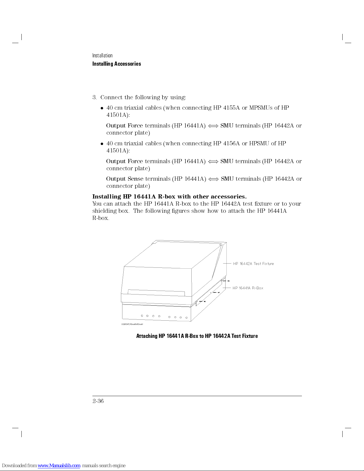
Installation
Installing Accessories
3. Connect the following by using:
40 cm triaxial cables (when connecting HP 4155A or MPSMUs of HP
41501A):
Output Force
connector plate)
40 cm triaxial cables (when connecting HP 4156A or HPSMU of HP
41501A):
Output Force
connector plate)
Output Sense
connector plate)
Installing HP 16441A R-box with other accessories.
You can attach the HP 16441A R-box to the HP 16442A test xture or to your
shielding box. The following gures show how to attach the HP 16441A
R-box.
terminals (HP 16441A)
terminals (HP 16441A)
terminals (HP 16441A)
()
()
()
SMU
terminals (HP 16442A or
SMU
terminals (HP 16442A or
SMU
terminals (HP 16442A or
2-36
Attaching HP 16441A R-Box to HP 16442A T
est Fixture
Page 84

Attaching HP 16441A R-Box to Shielding Box
Installation
Installing Accessories
2-37
Page 85

Installation
Installing Accessories
To Install HP 16440A SMU/Pulse Generator Selector
Note that to use the HP 16440A, the HP 4155A/4156A must be equipped with
an HP 41501A SMU/Pulse Generator Expander that has two PGUs.
Attaching your HP 16440A selector to HP 16442A test xture
1. Put the HP 16440A selector on your workbench. 2. Put the HP 16442A test xture on top of HP 16440A
selector.
3. Put a plate on both sides. 4. Screw the three furnished athead screws into each plate
2-38
.
Page 86

Installation
Installing Accessories
If you do
5. Put the HP 16440A selector
6. Put a plate on both sides. 7. Screw the three furnished athead screws into each plate
not
use an HP 16440A SMU/Pulse Generator Selector
expander
on your workbench.
Then, put the HP 16440A selector and HP 16442A test
xture (that were attached in the previous steps) on top
of the HP 16440A selector
expander
.
expander
, skip the following steps:
.
2-39
Page 87
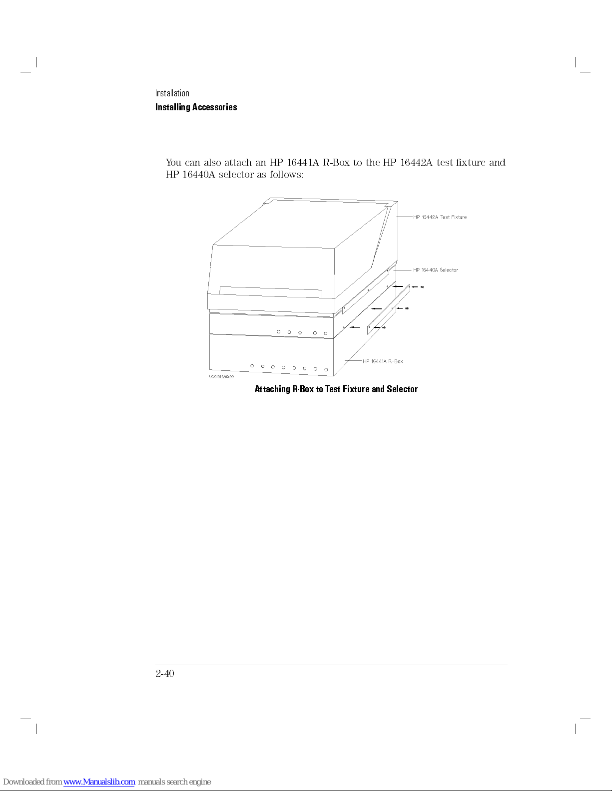
Installation
Installing Accessories
You can also attach an HP 16441A R-Box to the HP 16442A test xture and
HP 16440A selector as follows:
2-40
Attaching R-Box to Test Fixture and Selector
Page 88
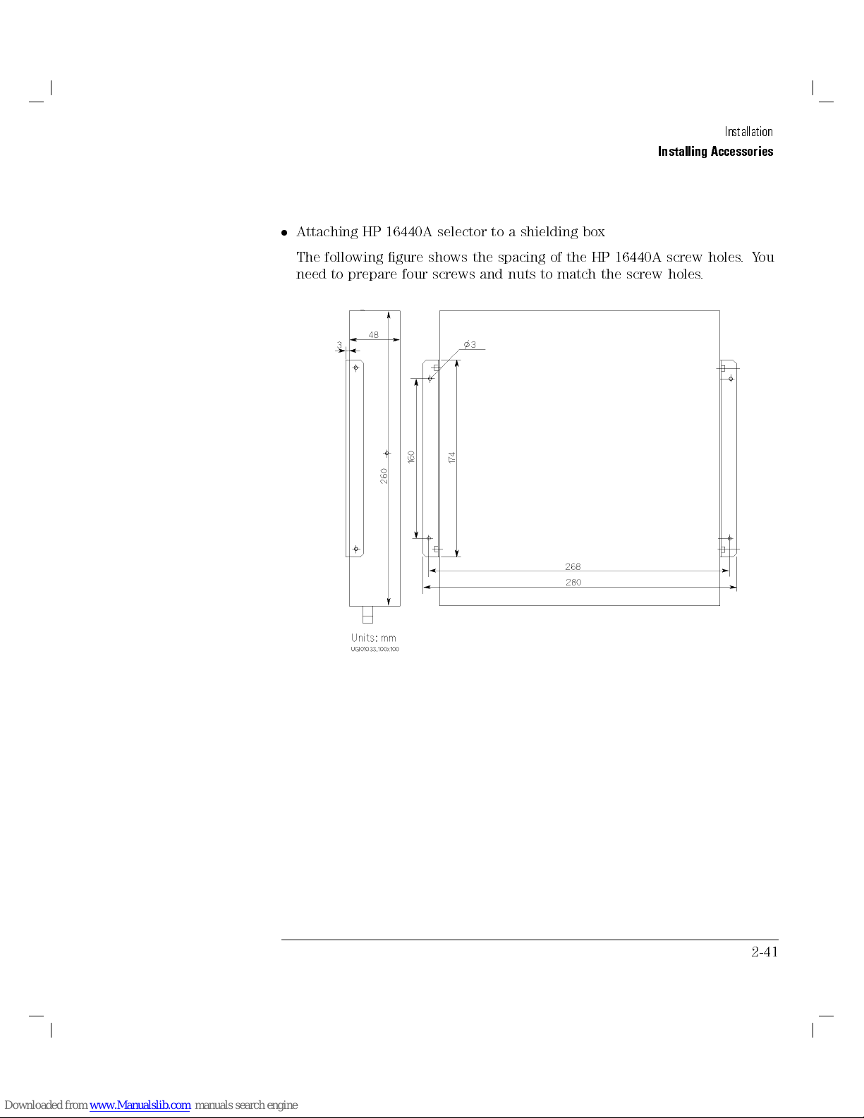
Installation
Installing Accessories
Attaching HP 16440A selector to a shielding box
The following gure shows the spacing of the HP 16440A screw holes.You
need to prepare four screws and nuts to match the screw holes.
2-41
Page 89
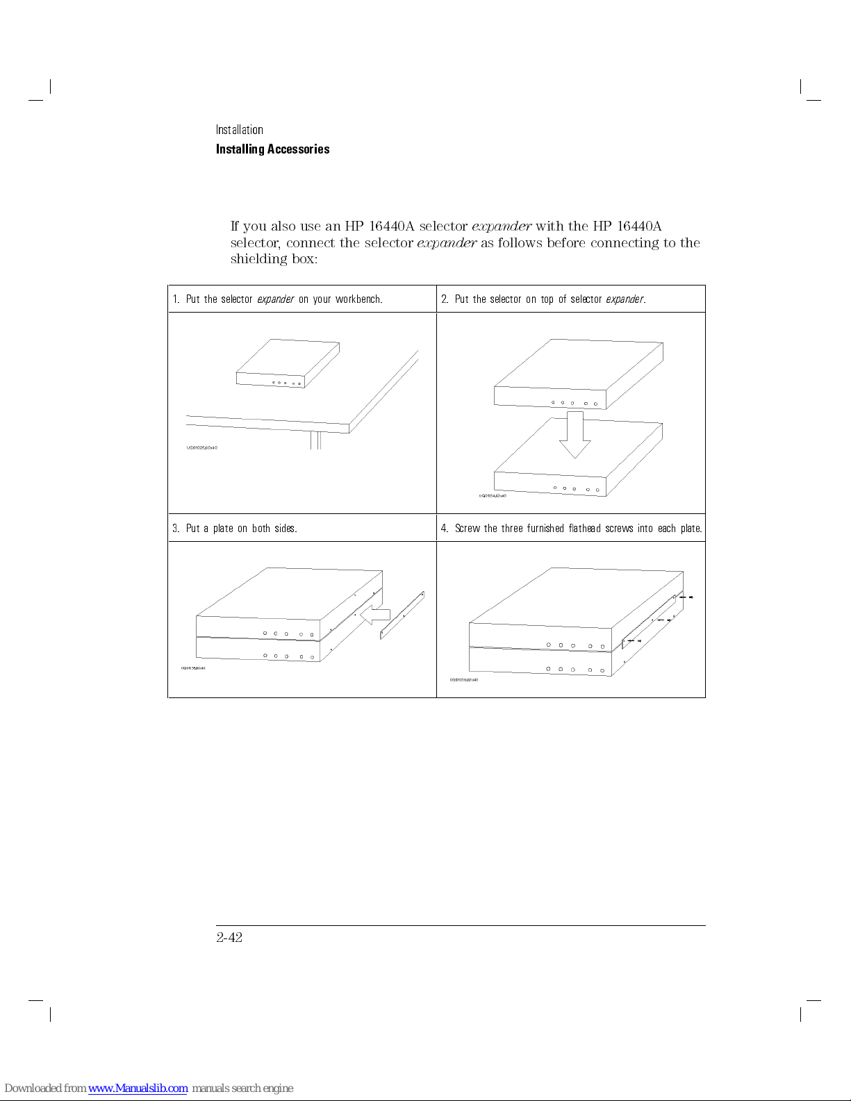
Installation
Installing Accessories
If you also use an HP 16440A selector
selector, connect the selector
shielding box:
1. Put the selector
3. Put a plate on both sides. 4. Screw the three furnished athead screws into each plate
expander
on your workbench. 2. Put the selector on top of selector
expander
expander
as follows before connecting to the
with the HP 16440A
expander
.
.
2-42
Page 90

Installation
Installing Accessories
Connect selector (and selector
procedure) to shielding box as follows:
1. Attach an angle to both sides of HP 16440A by using the furnished screws.
2. Put the HP 16440A(s) on the side panel of your shielding
box.
3. Put four nuts on the inside panel of your shielding box.
4. Screw four athead screws into the side panel.
expander
if connected by previous
2-43
Page 91
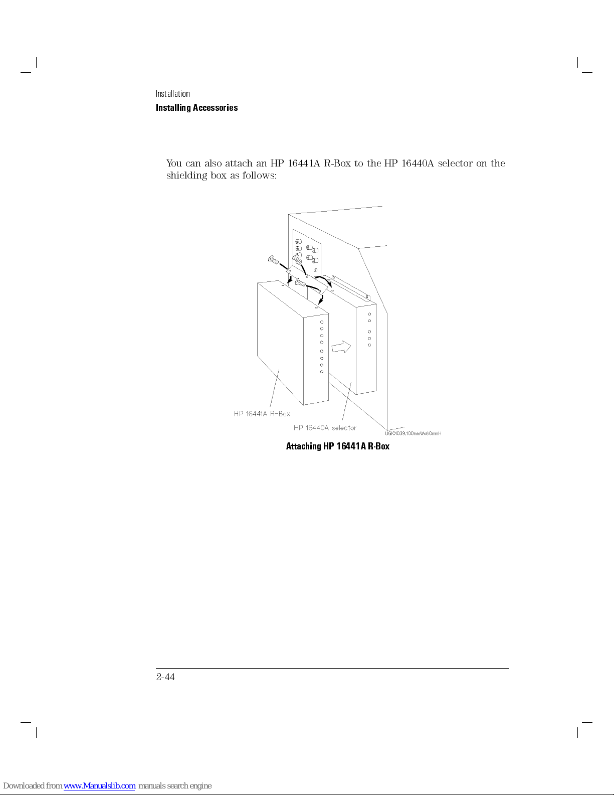
Installation
Installing Accessories
You can also attach an HP 16441A R-Box to the HP 16440A selector on the
shielding box as follows:
2-44
Attaching HP 16441A R-Box
Page 92

Installation
Installing Accessories
To Connect HP 16440A Selector to HP 4155A/56A
Connecting HP 16440A selector to HP 16440A selector
expander
If you use selector
using 40 cm control cable as follows:
CONTROL Output
(selector
expander
expander
terminal (selector)
)
, connect selector to selector
()
CONTROL Input
expander
terminal
by
2-45
Page 93

Installation
Installing Accessories
Connecting HP 16440A selector to HP 4155A/4156A
Before connecting, turn o HP 4155A/4156A and HP 41501A.
1. Connect the following by using a 3.0 m or 1.5 m control cable:
CONTROL Input
Selector Interface
Repeat following steps for desired channels of selector (or expander)
2. Connect the following by using a 3.0 m or 1.5 m triaxial cable:
Input SMU
41501A)
3. Connect the following by using a 3.0 m or 1.5 m coaxial cable:
Input PGU
4. Connect the following by using a 40 cm triaxial cable:
Output Selected
or HP 16442A test xture).
2-46
terminal (selector)
terminal (HP 41501A).
terminal (selector)
terminal (selector)
terminal (selector)
()
()
()
To SMU/Pulse Generator
SMU
terminal (HP 4155A/56A or HP
PGU
terminal (HP 41501A).
()
SMU
terminal (connector plate
Page 94

3
Making a Measurement
Page 95

Making a Measurement
To make a measurement, mount your device under test (DUT), set up your
HP 4155A/4156A for the measurement, then execute the measurement. The
HP 4155A/4156A can execute sweep and sampling measurements. The HP
4155A/4156A can also force stress to your DUT.
This chapter describes the tasks for making measurements, and is organized
into the following four sections:
Connection to Device Under Test (DUT)
Sweep Measurements
Knob Sweep Measurements
Sampling Measurements
Stress Force
For details about how to enter or input setup data, refer to \P
Organization" in
To satisfy the specications of HP 4155A/4156A and HP 41501A measurement
accuracy, perform calibration and adjustment every year and allow HP
4155A/4156A and HP 41501A to warm-up for a minimum of 40 minutes
before you begin performing measurements.
HP 4155A/4156A User's Dictionary Reference
age
.
3-2
Page 96

Connection to Device Under Test (DUT)
This section describes how to connect your DUTs to the HP 4155A/4156A.
Only the basic operations for connecting are described.
If the HP 4155A/4156A is not congured with a test xture or your wafer
prober yet, see \Setting up HP 4155A/4156A" in Chapter 2,
User's Guide
This section covers the HP 16442A test xture only.For operating your wafer
prober, see your wafer prober manuals.
Note that you must set the HP 4155A/4156A to the idle state when
connecting or disconnecting your DUTs. If not, the DUTs may be damaged. To
set to idle state, press
, and your wafer prober manuals.
4
5
key and make sure Standby indicator is o.
Stop
Test Fixture
The HP 4156A is designed for
Connections to Measure Low Resistance (For HP 4156A Only)" for Kelvin
connection theory.
In this Section.
This section has the following task descriptions:
To mount a DUT on test xture
To make connections to reduce leakage current
To make connections to measure low resistance (for HP 4156A only)
Kelvin connections
. See \To Make
3-3
Page 97

Making a Measurement
Connection to Device Under Test (DUT)
To Mount a DUT on Test Fixture
CAUTION
1. Set your HP 4155A/4156A to idle state by pressing
MEASUREMENT key group. If the standby indicator is lit, press the
4
2. Select a proper socket module for your DUT, then set the module on the
test xture.
3. Mount your DUT on the socket module.
4. Connect the terminals of the socket module to the terminals of the test
xture by using the proper cables.
5. Close the lid of the test xture, if necessary.
When the HP 4155A/4156A forces more than640 V, close the lid of the test
xture. Otherwise, the interlock function will stop the HP 4155A/4156A
output.
Do not connect or disconnect your DUT and HP 4155A/4156A while the HP
4155A/4156A is forcing voltage or current. Otherwise, your DUT may be
damaged.
To connect the DUT on the test xture, you can use cables that have the
following connectors:
Miniature banana|miniature banana
Miniature banana|pin plug
Miniature banana|miniature clip
Standby
5
key to turn o the standby indicator.
4
Stop
5
key in the
CAUTION
Do not touch the contact part of the connection cables. Oil, perspiration,
and dirt prevent good electrical contact, deteriorate insulation, and degrade
measurement accuracy.
3-4
Page 98
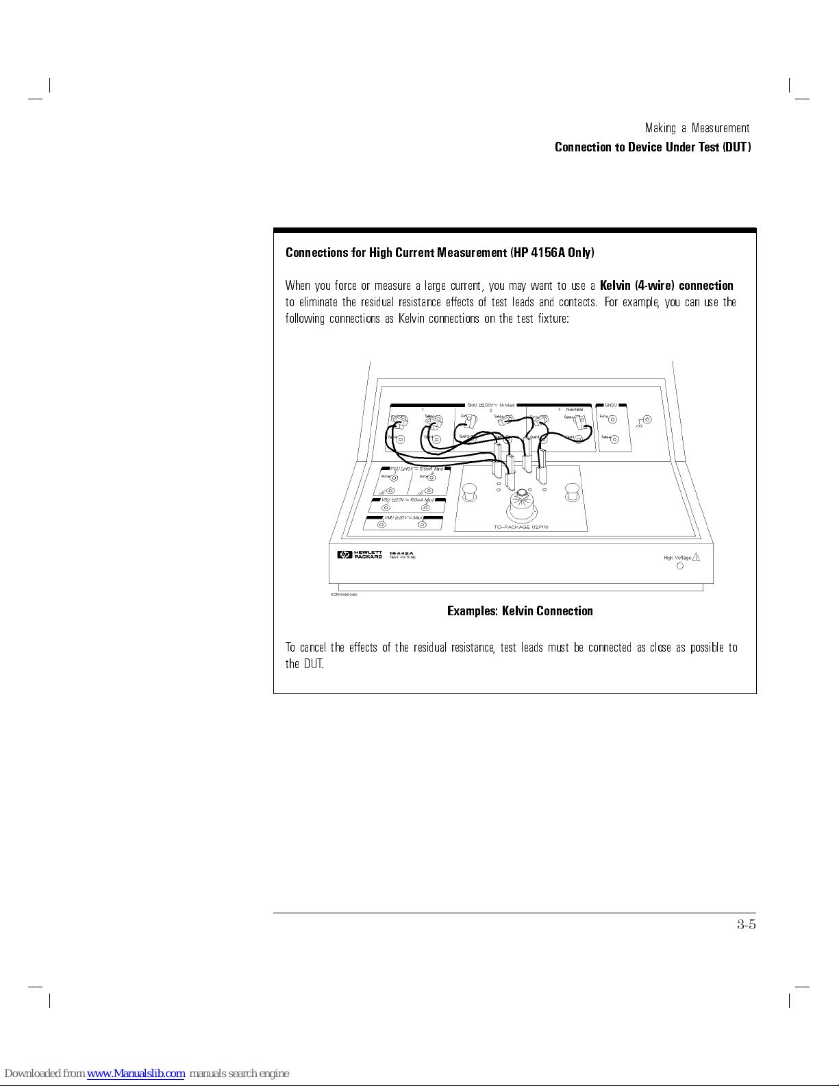
Connection to Device Under Test (DUT)
Connections for High Current Measurement (HP 4156A Only)
Making a Measurement
When you force or measure a large current, you may want to use a
to eliminate the residual resistance eects of test leads and contacts. For example, you can use the
following connections as Kelvin connections on the test xture:
Examples: Kelvin Connection
To cancel the eects of the residual resistance, test leads must be connected as close as possible to
the DUT.
Kelvin (4-wire) connection
3-5
Page 99
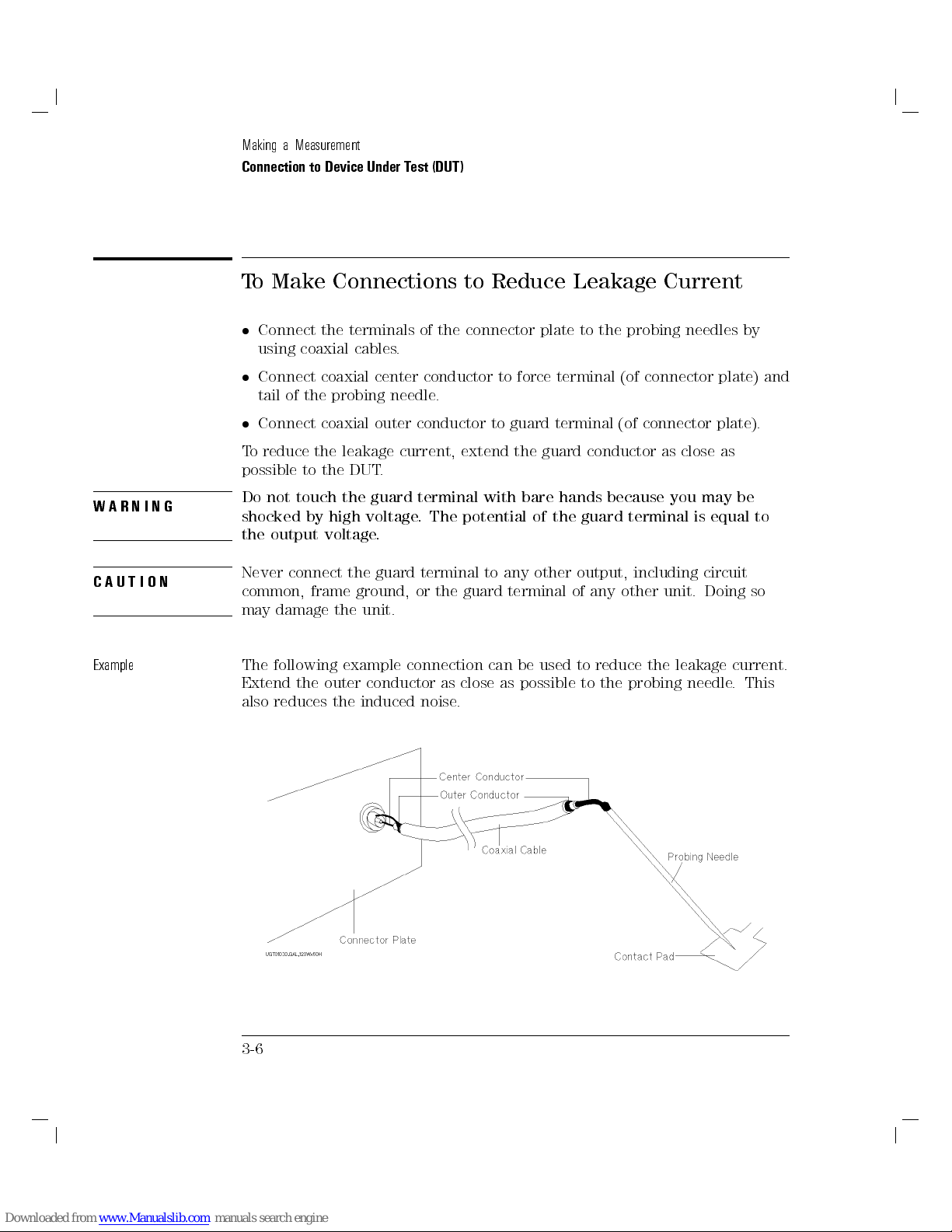
Making a Measurement
Connection to Device Under Test (DUT)
To Make Connections to Reduce Leakage Current
Connect the terminals of the connector plate to the probing needles by
using coaxial cables.
Connect coaxial center conductor to force terminal (of connector plate) and
tail of the probing needle.
Connect coaxial outer conductor to guard terminal (of connector plate).
To reduce the leakage current, extend the guard conductor as close as
possible to the DUT.
WARNING
CAUTION
Example
Do not touch the guard terminal with bare hands because you may be
shocked by high voltage. The potential of the guard terminal is equal to
the output voltage.
Never connect the guard terminal to any other output, including circuit
common, frame ground, or the guard terminal of any other unit. Doing so
may damage the unit.
The following example connection can be used to reduce the leakage current.
Extend the outer conductor as close as possible to the probing needle
also reduces the induced noise.
. This
3-6
Page 100

Making a Measurement
Connection to Device Under Test (DUT)
Guarding
Guarding reduces the leakage current between the measurement points and instrument. This is
important when you measure low current.
The following gure shows the theory of guarding. The buer amplier (21) keeps the potential of
the guard conductor at the same potential as the force conductor, so current does not ow between
the force and guard conductors. Therefore, the current measured by SMU is same as current at
measurement point because no current is leaked.
3-7
 Loading...