

Page 1

Artisan Technology Group is your source for quality
new and certied-used/pre-owned equipment
• FAST SHIPPING AND
DELIVERY
• TENS OF THOUSANDS OF
IN-STOCK ITEMS
• EQUIPMENT DEMOS
• HUNDREDS OF
MANUFACTURERS
SUPPORTED
• LEASING/MONTHLY
RENTALS
• ITAR CERTIFIED
SECURE ASSET SOLUTIONS
SERVICE CENTER REPAIRS
Experienced engineers and technicians on staff
at our full-service, in-house repair center
Instra
Remotely inspect equipment before purchasing with
our interactive website at www.instraview.com
Contact us: (888) 88-SOURCE | sales@artisantg.com | www.artisantg.com
SM
REMOTE INSPECTION
View
WE BUY USED EQUIPMENT
Sell your excess, underutilized, and idle used equipment
We also offer credit for buy-backs and trade-ins
www.artisantg.com/WeBuyEquipment
LOOKING FOR MORE INFORMATION?
Visit us on the web at www.artisantg.com for more
information on price quotations, drivers, technical
specications, manuals, and documentation
Page 2

Parameter Analyzer
Quick Start Guide
Page 3
c
Copyright Hewlett-Packard
Company 1993
All Right Reserved.
Reproduction, adaptation, or
translation without prior written
permission is prohibited, except as
allowed under the copyright laws.
HP Part Number
04155-90200
First edition, September 1993
Printed in Japan
Product Warranty
This Hewlett-Packard product is warranted against
defects in material and workmanship for a period of
one year from date of shipment. During the warranty
period, Hewlett-Packard will, at its option, either repair
or replace products which prove to be defective.
Warranty service of this product will be performed at
Buyer's facility at no charge within Hewlett-Packard
service travel areas. Outside Hewlett-Packard service
travel areas, warranty service will be performed at
Buyer's facility only upon Hewlett-Packard's prior
agreement and Buyer shall pay Hewlett-Packard's
round trip travel expenses. In all other cases, products
must be returned to a service facility designated b
y
Hewlett-Packard.
For products returned to Hewlett-Packard for warranty
service, Buyer shall prepay shipping charges to
Hewlett-Packard and Hewlett-Packard shall pay
shipping charges to return the product to Buyer.
However, Buyer shall pay all shipping charges, duties,
and taxes for products returned to Hewlett-Packard
from another country.
Hewlett-Packard warrants that its software and
rmware designated by Hewlett-Packard for use with
an instrument will execute its programming
instructions when properly installed on that instrument.
Hewlett-Packard does not warrant that the operation
of the instrument, or software, or rmware will be
uninterrupted or error free.
Limitation of Warranty
The foregoing warranty shall not apply to defects
resulting from improper or inadequate maintenance by
Buyer, Buyer-supplied software or interfacing,
unauthorized modications or misuse, operation outside
of the environment specications for the products, or
improper site preparation or maintenance.
No other warranty is expressed or implied.
Hewlett-Packard specically disclaims the implied
warranties of merchantability and tness for a
particular purpose.
Exclusive Remedies
The remedies provided herein are the Buyer's sole and
exclusive remedies. Hewlett-Packard shall not be liable
for any direct, indirect, special, incidental, or
consequential damages, whether based on contract,
tort, or any other legal theory.
Assistance
Product maintenance agreements and other customer
assistance agreements are available for
Hewlett-Packard products.
For any assistance, contact your nearest
Hewlett-Packard Sales Oce.
Certication
Hewlett-Packard Company certies that this product
met its published specications at the time of shipment
[from the factory]. Hewlett-Packard further certies
that its calibration measurements are traceable to the
National Institute of Standards and Technology
(
NIST
), to the extent allowed by the Institute's
calibration facility, and to the calibration facilities of
other International Standards Organization members.
Yokogawa-Hewlett-Packard, Ltd.
9-1, Takakura-cho, Hachioji-shi, Tokyo 192 Japan
Page 4

HP 4155A and HP 4156A
HP 4155A Semiconductor Parameter Analyzer and HP 4156A Precision
Semiconductor Parameter Analyzer are full automatic and high performance
instruments designed to measure, to display graphically, and to analyze the
dc parameters and characteristics of semiconductor devices such as diodes,
transistors, ICs, solar cells, and wafers during the fabrication process. So you
can evaluate device design, process design, fabrication environments, and so
on with the HP 4155A/4156A.
In semiconductor research and development laboratories
4155A/4156A provides precise characteristics evaluation, which is an
important step in the development of new high performance devices
and gives design engineers an easy to use method of device parameter
acquisition|an essential element in computer aided design (CAD).
On the production line, the HP 4155A/4156A provides real-time feedback
on wafer evaluation to improve the semiconductor process and to increase
production yields.
For semiconductor end users, the HP 4155A/4156A is ideal for circuit design
applications and incoming inspection.
, the HP
,
3
Page 5
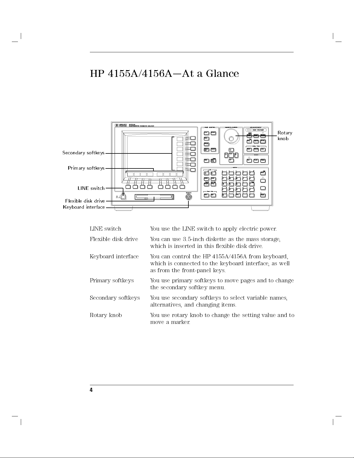
HP 4155A/4156A|At a Glance
Secondary softkeys
Primary softkeys
LINE switch
Flexible disk drive
Keyboard interface
Rotary
knob
LINE switch You use the LINE switch to apply electric power
Flexible disk drive You can use 3.5-inch diskette as the mass storage
which is inserted in this exible disk drive.
Keyboard interface You can control the HP 4155A/4156A from keyboard,
which is connected to the keyboard interface, as well
as from the front-panel keys.
Primary softkeys You use primary softkeys to move pages and to change
the secondary softkey menu.
Secondary softkeys You use secondary softkeys to select variable names,
alternatives, and changing items.
Rotary knob You use rotary knob to change the setting value and to
move a marker.
4
.
,
Page 6
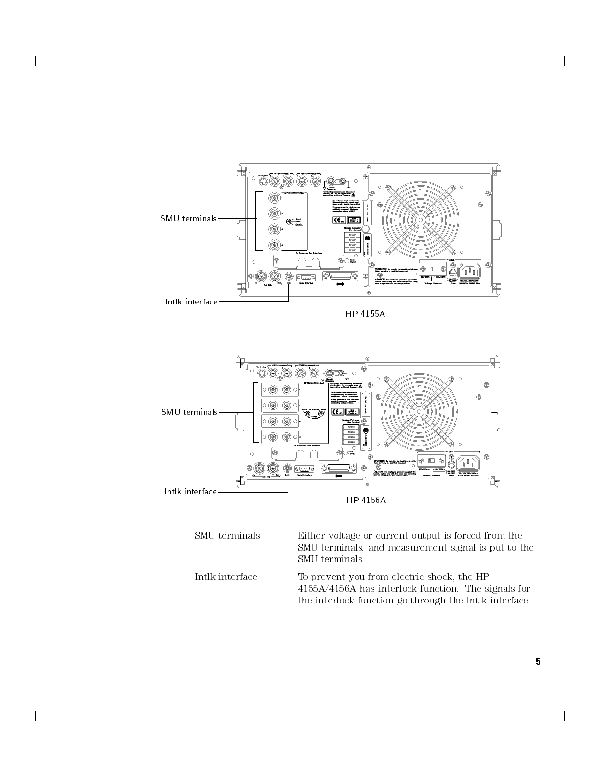
SMU terminals
Intlk interface
SMU terminals
HP 4155A
Intlk interface
SMU terminals Either voltage or current output is forced from the
Intlk interface To prevent you from electric shock, the HP
HP 4156A
SMU terminals, and measurement signal is put to the
SMU terminals.
4155A/4156A has interlock function. The signals for
the interlock function go through the Intlk interface.
5
Page 7
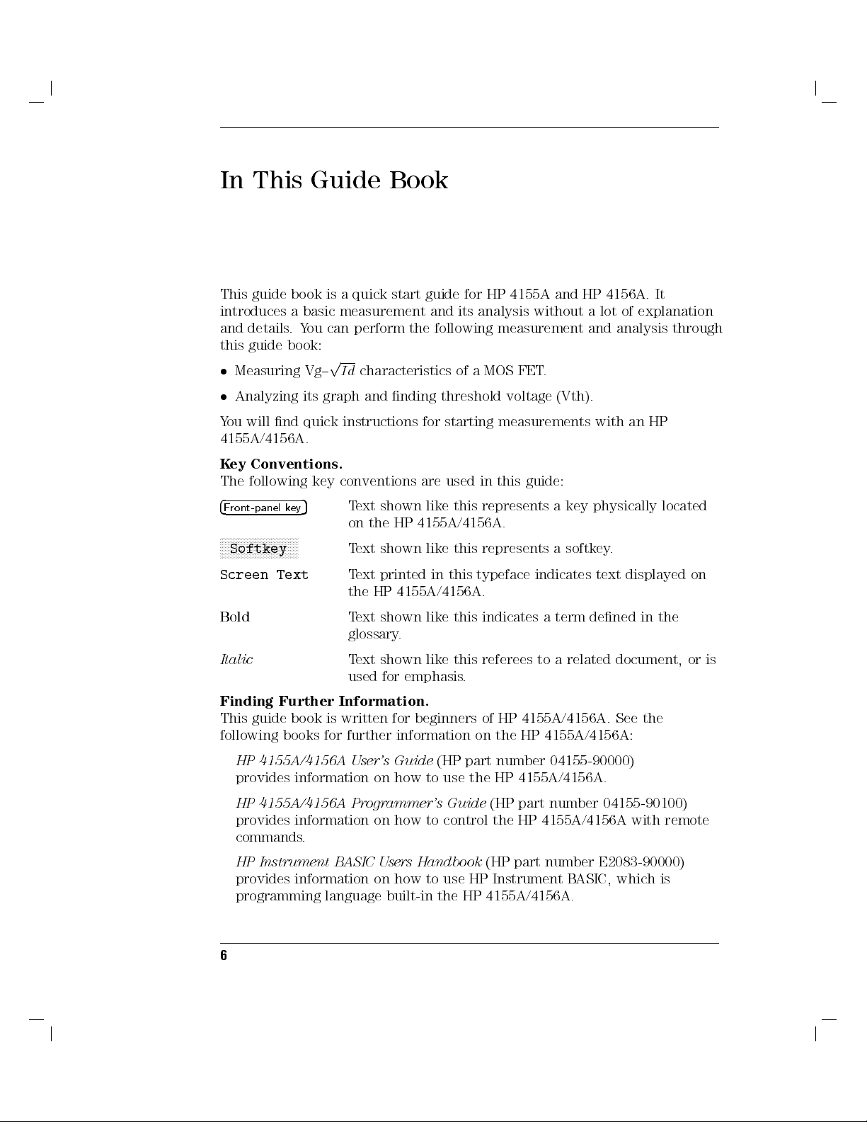
In This Guide Book
This guide book is a quick start guide for HP 4155A and HP 4156A. It
introduces a basic measurement and its analysis without a lot of explanation
and details.You can perform the following measurement and analysis through
this guide book:
Measuring Vg{pId
Analyzing its graph and nding threshold voltage (Vth).
characteristics of a MOS FET.
You will nd quick instructions for starting measurements with an HP
4155A/4156A.
Key Conventions.
The following key conventions are used in this guide:
4
Front-panel key
5
Text shown like this represents a key physically located
on the HP 4155A/4156A.
NNNNNNNNNNNNNNNNNNNNNNNNNNNNN
Softkey
Screen Text
Text shown like this represents a softkey.
Text printed in this typeface indicates text displayed on
the HP 4155A/4156A.
Bold
Text shown like this indicates a term dened in the
glossary.
Italic
Text shown like this referees to a related document, or is
used for emphasis.
Finding Further Information.
This guide book is written for beginners of HP 4155A/4156A. See the
following books for further information on the HP 4155A/4156A:
HP 4155A/4156A User's Guide
(HP part number 04155-90000)
provides information on how to use the HP 4155A/4156A.
HP 4155A/4156A Programmer's Guide
(HP part number 04155-90100)
provides information on how to control the HP 4155A/4156A with remote
commands.
HP Instrument BASIC Users Handbook
(HP part number E2083-90000)
provides information on how to use HP Instrument BASIC, which is
programming language built-in the HP 4155A/4156A.
6
Page 8

Getting Started
Page 9

Getting Started
This guide introduces how to use HP 4155A Semiconductor Parameter
Analyzer and HP 4156A Precision Semiconductor Parameter Analyzer. Basic
operations of the HP 4155A/4156A are provided.
This guide consists of the following three sections:
Making a measurement
sample device (MOS FET).
Analyzing a result
threshold voltage (Vth) of the MOS FET.
If you have a problem
encounter while using this guide.
Before going to the next page, make sure you have prepared the following:
HP 4155A or HP 4156A
HP 16442A test xture
Test device (n-channel MOS FET, enhancement type)
In this guide, the test device used is a Siliconix SD214DE.
: preparing for measurements and measuring a
: analyzing the results graphically and searching for the
: providing solutions to problems you may
This guide book assumes that you have already installed
your HP 4155A/4156A. If not, refer to \Installation" in the
HP 4155A/4156A User's Task Guide.
2
.
Page 10
Making a Measurement
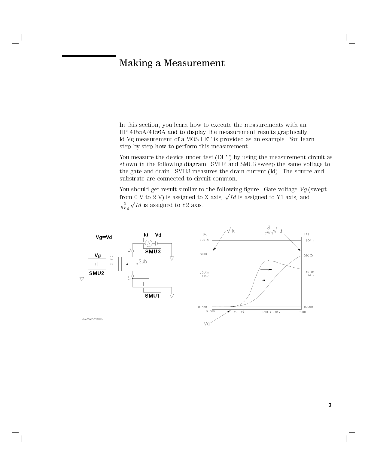
In this section, you learn how to execute the measurements with an
HP 4155A/4156A and to display the measurement results graphically.
Id-Vg measurement of a MOS FET is provided as an example.You learn
step-by-step how to perform this measurement.
You measure the device under test (DUT) by using the measurement circuit as
shown in the following diagram. SMU2 and SMU3 sweep the same voltage to
the gate and drain. SMU3 measures the drain current (Id). The source and
substrate are connected to circuit common.
You should get result similar to the following gure
from 0 V to 2 V) is assigned to X axis
p
@
Id
@V g
is assigned to Y2 axis.
p
,
Id
is assigned to Y1 axis, and
. Gate voltageVg(swept
3
Page 11
Getting Started
Making a Measurement
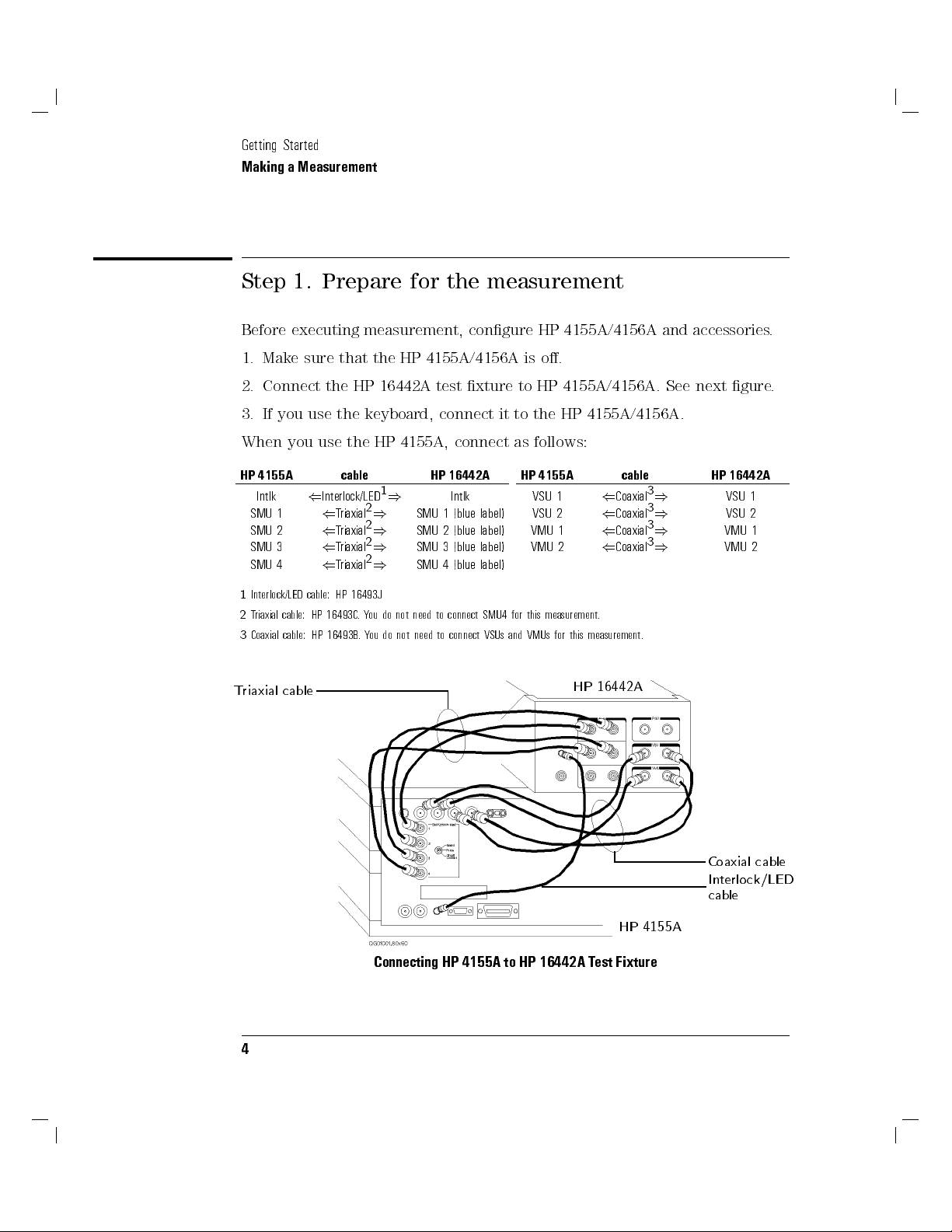
Step 1. Prepare for the measurement
Before executing measurement, congure HP 4155A/4156A and accessories.
1. Make sure that the HP 4155A/4156A is o.
2. Connect the HP 16442A test xture to HP 4155A/4156A. See next gure.
3. If you use the keyboard, connect it to the HP 4155A/4156A.
When you use the HP 4155A, connect as follows:
HP 4155A cable HP 16442A
Triaxial
Triaxial
Triaxial
Triaxial
1
)
2
)
2
)
2
)
2
)
Intlk
SMU 1 (blue label)
SMU 2 (blue label)
SMU 3 (blue label)
SMU 4 (blue label)
Intlk
SMU 1
SMU 2
SMU 3
SMU 4
1
Interlock/LED cable: HP 16493J
2
Triaxial cable: HP 16493C.You do not need to connect SMU4 for this measurement.
3
Coaxial cable: HP 16493B.You do not need to connect VSUs and VMUs for this measurement.
(
Interlock/LED
(
(
(
(
Triaxial cable
HP 4155A cable HP 16442A
VSU 1
VSU 2
VMU 1
VMU 2
HP 16442A
(
(
(
(
Coaxial
Coaxial
Coaxial
Coaxial
3
)
3
)
3
)
3
)
VSU 1
VSU 2
VMU 1
VMU 2
Coaxial cable
Interlock/LED
cable
HP 4155A
Connecting HP 4155A to HP 16442A Test Fixture
4
Page 12

When you use the HP 4156A, connect as follows:
Getting Started
Making a Measurement
HP 4156A cable HP 16442A
Intlk
SMU 1
SMU 2
SMU 3
1
Interlock/LED cable: HP 16493J
2
Kelvin triaxial cable: HP part number 04155-61602
3
Coaxial cable: HP 16493B.You do not need to connect VSUs and VMUs for this measurement.
Kelvin triaxial cable
(
Interlock/LED1)
(
Kelvin triaxial2)
(
Kelvin triaxial2)
(
Kelvin triaxial2)
Intlk
SMU 1
SMU 2
SMU 3
HP 4156A cable HP 16442A
VSU 1
VSU 2
VMU 1
VMU 2
(
Coaxial3)
(
Coaxial3)
(
Coaxial3)
(
Coaxial3)
VSU 1
VSU 2
VMU 1
VMU 2
HP 16442A
Coaxial cable
Interlock/LED
cable
HP 4156A
Connecting HP 4156A to HP 16442A Test Fixture
5
Page 13

Getting Started
Making a Measurement
Step 2. Mount your DUT on the test xture
1. Select a suitable socket module for your DUT.
2. Mount the socket module on the test xture.
Socket module
HP 16442A Test Fixture
3. Mount your DUT on the socket module.
4. Make connections with four connection cables (miniature banana { pin
plug).
You make the following connections:
Source|SMU1
Gate|SMU2
Drain|SMU3
Substrate|SMU1
Both the source and substrate terminals are connected to SMU1.
5. After nishing connections, shut the lid of the test xture.
6
Page 14

Connection cables
Getting Started
Making a Measurement
DUT
Gate
Drain
Source
Substrate
Wiring for HP 4155A
For this measurement by the HP 4156A, non-Kelvin connections are used. So,
connect only the force terminals as shown in the following gure:
Connection cables
DUT
Gate
Drain
Source
Substrate
Wiring for HP 4156A
7
Page 15

Getting Started
Making a Measurement
Step 3. Dene the channel assignments
You set the connection information on the CHANNELS: CHANNEL
DEFINITION page.
1. Switch on the HP 4155A/4156A. Self-test starts.
2. After self-test is nished, make sure that CHANNELS: CHANNEL
DEFINITION page appears on the screen of the HP 4155A/4156A. If not,
press
4
5
front-panel key.
Chan
CHANNELS: CHANNEL DEFINITION page
MEASUREMENT MODE
Secondary
softkeys
Primary softkeys
3. Make sure that
not, select
4. Set the connection information in the CHANNELS table as follows:
8
SWEEP
NNNNNNNNNNNNNNNNN
SWEEP
is displayed in the MEASUREMENT MODE eld. If
secondary softkey in the MEASUREMENT MODE eld.
Page 16

Getting Started
Making a Measurement
Action on Front Panel on Keyboard
To move the pointer, use
4
5,4
5,4
5
,or
(
)
4
*
+
area.
To move the cursor to edit in display area,
use
4
(
5or4
5
of Edit area. use
)
To enter \VS" in VNAME eld, pressV4.5",S4+5n, then
To enter \IS" in INAME eld, pressI4*5?,S4+5n, then
To set \V" in the MODE eld, select
To set \
VAR1'
"inFCTN eld, select
To set \
VAR1
"inFCTN eld, select
To disable a unit, select
FFFFFFFFFF
V
secondary softkey. press
FFFFFFFFFFFFFFFF
VAR1'
FFFFFFFFFFFFF
VAR1
FFFFFFFFFFFFFFFFFFFFFFFFFFFFFFFFFFF
DISABLE UNIT
secondary softkey. press
secondary softkey. press
5
of MARKER/CURSOR
4
5
. typeVS, then press
Enter
4
5
. typeIS, then press
Enter
use
secondary softkey. press
4
5,4
5,4
6
7
4
Backspace
4
5-4
Shift
4
5-4
Shift
4
5-4
Shift
4
5-4
Shift
8
F1
F4
F2
F7
5
,or
5
5
5
5
5
4
5
9
key.
4
Enter
4
Enter
keys.
keys.
keys.
keys.
.
5
.
5
.
9
Page 17

Getting Started
Making a Measurement
Step 4. Dene the user functions
You dene the user functions on the CHANNELS: USER FUNCTION
DEFINITION page.
1.
Select
DEFINITION page appears.
2. Enter the user function information in the table as follows:
CHANNELS: USER FUNCTION DEFINITION page
NNNNNNNNNNNNNNNNNNNNNNNNNNNNN
USER FCTN
primary softkey. The CHANNELS: USER FUNCTION
You enter the following two user functions:
SQID =pId
DSQID =
Where,Idis drain current andVgis gate voltage.
10
@
@
Vg
SQID =
p
@
Id
@
Vg
Page 18

Getting Started
Making a Measurement
Action on Front Panel on Keyboard
To move the pointer, use
area.
To move the cursor to edit in display area, use
To enter \
To enter \
eld,
To enter \
SQID
" in NAME eld, pressS4+5n,Q425',I4*5?,D4/5;, then
4
Enter
SQRT(ID)
1
"
in DEFINITION
pressS4+5n,Q425',R435j,T4p5%,
(blue key),
DSQID
" in NAME eld, pressD4/5;,S4+5n,Q425',I4*5?,D4/5;,
then
To enter \
DIFF(SQID,VG)
DEFINITION eld,
2
"
in
pressD4/5;,I4*5?,F475f,F475f,45(blue
key),
I
4*5?,D4/5;,45(blue key),
B
4)5], then
To disable a user function, select
4(5,4)5,4*5
4(5or4)5
5
.
A
4
Enter
A
4(5[,45(blue key),
FFFFFFFFFFFFFFFFFFFFFFFFFFFFFFFFFFFFFFFFFFFFFF
DISABLE FUNCTION
,or
4+5
of Edit area. use
FFFFFFF
4(5[,
ID
,B4)5], then
5
.
4
5
.
Enter
of MARKER/CURSOR
4
Enter
S
4+5n,Q425',
X
4,5>,
FFFFFFF
VG
secondary softkey. press
45
5
,
use
465,475,485
4
Backspace
type
SQID
type
SQRT(ID)
4
5
Enter
.
type
DSQID
type
DIFF(SQID,VG)
4
5
Enter
4
Shift
, then press
.
, then press
.
5-4
F7
,or
495
.
5
key.
4
Enter
, then press
4
Enter
, then press
5
key.
5
.
5
.
1
Square root operator (p) is dened by \SQRT" built-in function.
2
Partial dierence (
@
) is dened by \DIFF" built-in function.
@
11
Page 19

Getting Started
Making a Measurement
Step 5. Set up the measurement parameters
You set the output parameters on the MEASURE: SWEEP SETUP page.
1. Press
MEASURE: SWEEP SETUP page
VAR1 information
2. Set the VAR1 information as follows:
4
5
front-panel key. The MEASURE: SWEEP SETUP page appears.
Meas
VAR1'
information
12
Page 20

Getting Started
Making a Measurement
Drain voltage sweeps from 0 V to 2 V with 10 mV step. The current
compliance is set to 100 mA.
Action on Front Panel on Keyboard
To move the pointer, use
To set \
To set \
To enter \
To enter \
SINGLE
LINEAR
" in SWEEP MODE eld, select
" in LIN/LOG eld, select
2.000 V
10.00 mV
"inSTOP eld, pressQ425', then
" in STEP eld, pressP415$,U405#,E4m5@, then
3. Set the VAR1' information as follows:
To force the same voltage to the drain and gate
OFFSET
= 0. Because VAR1' is dened as follows:
(
VAR
10output)=RAT IO2(
4(5,4)5,4*5
FFFFFFFFFFFFFFFFFF
SINGLE
FFFFFFFFFFFFFFFFFF
LINEAR
secondary softkey. press
secondary softkey. press
,or
4
Enter
4+5
. use
5
. type2, then press
4
Enter
5
. type
, set
465,475,485
4
Shift
4
Shift
10m
RATIO
VAR1output)+OFFSET
,or
5-4F15
5-4F15
, then press
= 1 and
495
keys.
keys.
4
Enter
4
.
5
Enter
.
5
.
To enter \
To enter \
Action on Front Panel on Keyboard
0.000 V
1.000
" in OFFSET eld, pressU405#, then
"inRATIO eld, pressP415$, then
4
Enter
4
Enter
5
. type0, then press
5
. type1, then press
4
Enter
4
Enter
5
.
5
.
13
Page 21

Getting Started
Making a Measurement
Step 6. Set up the results display
You set the results display information on the DISPLAY: DISPLAY SETUP page.
1. Press
DISPLAY: DISPLAY SETUP page
DISPLAY MODE
2. Make sure
3. Set the X-, Y1-, and Y2-axes information as follows:
4
appears.
NNNNNNNNNNNNNNNNNNNNNNN
select
5
Display
GRAPHICS
GRAPHIC
front-panel key. The DISPLAY: DISPLAY SETUP page
is displayed in the DISPLAY MODE eld. If not,
secondary softkey in the DISPLAY MODE eld.
14
Page 22

Action on Front Panel on Keyboard
To enter \VG" in NAME eld, select
To set \
LINEAR
" in SCALE eld, select
FFFFFFFFFF
VG
secondary softkey. press
FFFFFFFFFFFFFFFFFF
LINEAR
secondary softkey. press
Getting Started
Making a Measurement
4
5-4F35
5-4F15
keys.
keys.
Shift
4
Shift
To enter \
To enter \
To enter \
To enter \
To enter \
To enter \
0.00000 V
2.00000 V
SQID
0.00000 A
100.000mA
DSQID
" in MIN eld, pressU405#, then
" in MAX eld, pressQ425', then
" in NAME eld, select
" in MIN eld, pressU405#, then
" in MAX eld, pressP415$,U405#,U405#,E4m5@, then
" in NAME eld, select
softkeys.
4
Enter
softkeys.
FFFFFFFFFFFFFFFFFFFFFFFF
MORE 1/2
5
.
FFFFFFFFFFFFFFFFFFFFFFFF
MORE 1/2
4
Enter
4
Enter
, then
4
Enter
, then
5
. type0, then press
5
. type2, then press
FFFFFFFFFFFFF
SQID
secondary
5
. type0, then press
FFFFFFFFFFFFFFFF
DSQID
secondary
press
4
Shift
type
press
4
Shift
4
Shift
5-4F35
100m
4
Shift
5-4
F4
4
Enter
4
Enter
5-4F75
keys.
4
Enter
, then press
5-4
5
F7
5
keys.
5
5
keys, then
5
4
Enter
keys, then
.
.
.
5
.
15
Page 23

Getting Started
Making a Measurement
Step 7. Execute the measurement
Press
4
5
front-panel key to execute the measurement.
Single
[Single] key
You should get measurement results similar to the following gure
16
.
Page 24

Analyzing the Results
In the previous section, you measured the drain current (Id) while performing
a synchronous sweep of the gate voltage (Vg) and drain voltage (Vd). And the
measurement results were drawn graphically on the screen.
In this section, you analyze the measurement results on the graph and search
threshold voltage (Vth) of the DUT.
The basic algorithm to search for the threshold voltage is:
1.
Assign gate voltage (Vg) to X-axis
2.
Search for the maximum value of
where the gradient ofpId
3.
Draw a tangent line to the point where the gradient ofpId
,
Id
to Y1-axis, and
p
@
Id
@V g
curve, which is also the point
curve is maximum.
p
@
@V g
p
Id
curve is
to Y2-axis.
maximum.
4. Read the X-coordinate value where the tangent line crosses the X-axis
This value is threshold value (Vth).
Tangent
Vth
.
17
Page 25

Getting Started
Analyzing the Results
Find the threshold voltage
1.
Make sure that
select the
MARKER/CURSOR primary softkey
NNNNNNNNNNNNNNNNNNNNNNNNNNNNNNNNNNNNNNNNN
MARKER/CURSOR
NNNNNNNNNNNNNNNNNNNNNNNNNNNNNNNNNNNNNNNNN
MARKER/CURSOR
primary softkey is highlighted. If not,
primary softkey.
18
Page 26

Getting Started
Analyzing the Results
2. Select
The
measurement curve.
3. Select
axis is highlighted.
NNNNNNNNNNNNNNNNNNNN
MARKER
NNNNNNNNNNNNNNNNNNNN
MARKER
Marker
NNNNNNNNNNNNNN
AXIS
secondary softkey so thatONappears on the softkey.
softkey is highlighted, and the markers appears on the
MARKER
secondary
softkey
primary softkey so thatY2appears on the softkey. The Y2
AXIS primary softkey
19
Page 27

Getting Started
Analyzing the Results
4. Select
the maximum point on the Y2 curve. Theomarker (on Y1 curve) also
moves to same X-axis point, which is maximum gradient of Y1 curve.
5. Select
axis is highlighted.
NNNNNNNNNNNNNNNNNNNNNNNNNNNNNNNNNNNNNNNNNNNN
MARKER MIN/MAX
Marker *
Marker o
NNNNNNNNNNNNNN
AXIS
primary softkey so that Y1 appears on the softkey
secondary softkey until the*marker moves to
MARKER
MIN/MAX
secondary
softkey
. The Y1
Y1 axis
AXIS primary softkey
20
Page 28

Getting Started
Analyzing the Results
6. Select
LINE primary softkey
7. Select
NNNNNNNNNNNNNN
the plotting area.
NNNNNNNNNNNNNN
LINE
NNNNNNNNNNNNNN
LINE
LINE
softkey is highlighted, and a vertical line appears in the center of
primary softkey. The secondary softkey menu changes.
Secondary
softkeys
secondary softkey so thatONappears on the softkey. The
Line
LINE
secondary
softkey
21
Page 29

Getting Started
Analyzing the Results
8. Select
o
Threshold voltage (Vth)
Read the X-axis intercept value of the tangent line
voltage (Vth). In the example above, Vth is 935 mV.
NNNNNNNNNNNNNNNNNNNNNNNNNNNNNNNNNNNNNN
TANGENT MODE
marker of the Y1 curve.
Marker o
secondary softkey. The line becomes tangent to the
A tangent
TANGENT
MODE
secondary
softkey
. This is the threshold
22
Page 30

If You Have a Problem
This section describes how to solve the following unexpected problems:
If HP 4155A/4156A cannot be powered on
If display page does not appear after applying power
If HP 16442A test xture is not stable
23
Page 31

Getting Started
If You Have a Problem
If HP 4155A/4156A cannot be powered on
Check that the power cable is rmly connected to HP 4155A/4156A and to
power outlet.
Check that the front-panel LINE switch is on.
Check that the voltage selector switch is set properly.
The voltage selector switch is located in the lower-right corner of the rear
panel. The following table shows the line voltage selector setting.
Line Voltage Position
84-124 Vac left
200-248 Vac right
Check that the fuse is good.
The fuse holders located in the lower-right corner of the rear panel.
1. Turn the HP 4155A/4156A o and disconnect the power cable from the
power outlet.
2. Unscrew the fuse holder on the rear panel.
3. Inspect that the correct fuse is installed, and wire inside the fuse is
broken by using a rester.
Line Fuse Type HP Part Number
110/120 Vac Time-delay type 8A, 250 Vac 2110-0383
220/240 Vac Time-delay type 4A, 250 Vac 2110-0014
4. Replace the fuse, if necessary. Then, screw in the fuse holder.
5. Turn the HP 4155A/4156A on.
24
not
Page 32

Getting Started
If You Have a Problem
If display page does not appear after applying power
If HP 41501 is installed,
rst
turn on the HP 41501,
then
turn on
HP 4155A/4156A.
If the self-test fails, see \If You Have a Problem" in the
User's Task Guide
.
HP 4155A/4156A
If HP 16442A test xture is not stable
Install stabilizers on the HP 16442A.
For this procedure, see \Installation" in the
Guide
.
If you use the HP 16442A test xture with HP 16440A selector or
HP 4155A/4156A User's Task
HP 16441A R-BOX, attach HP 16442A to HP 16440A or HP 16441A by
using plates and screws.
For this procedure, see \Installation" in the
Guide
.
HP 4155A/4156A User's Task
25
Page 33

Getting Started
If You Have a Problem
Page 34

Artisan Technology Group is your source for quality
new and certied-used/pre-owned equipment
• FAST SHIPPING AND
DELIVERY
• TENS OF THOUSANDS OF
IN-STOCK ITEMS
• EQUIPMENT DEMOS
• HUNDREDS OF
MANUFACTURERS
SUPPORTED
• LEASING/MONTHLY
RENTALS
• ITAR CERTIFIED
SECURE ASSET SOLUTIONS
SERVICE CENTER REPAIRS
Experienced engineers and technicians on staff
at our full-service, in-house repair center
Instra
Remotely inspect equipment before purchasing with
our interactive website at www.instraview.com
Contact us: (888) 88-SOURCE | sales@artisantg.com | www.artisantg.com
SM
REMOTE INSPECTION
View
WE BUY USED EQUIPMENT
Sell your excess, underutilized, and idle used equipment
We also offer credit for buy-backs and trade-ins
www.artisantg.com/WeBuyEquipment
LOOKING FOR MORE INFORMATION?
Visit us on the web at www.artisantg.com for more
information on price quotations, drivers, technical
specications, manuals, and documentation
 Loading...