

Page 1

I.
:
HP
..
.
This vintage Hewlett Packard document was
preserved and distributed by
Archive
www.
'
Please visit us on the web
..
On-line curator: Tony Gerbic
hparchive.com
!
Page 2
i
i
(r,
,'
a
I
i
f
DC
OPERATING
(HP
MODEL
VACUUM
SERIALS
PREFIXED: 301-, 3160, 424-,
AND
PART
SERVICE
NO.
00412-90003)
412A/AR
TUSE
MANUAL
VOLTMETER
I
649-
P.
1
i
OOT29-5
Copyright Hewlett-Packard
0.
Box
301,
Loveland,
Colorado,
Company
80537
1961
U.
S.A.
Printod:
NOV
1968
Page 3
0
h
Model 4 12A
TABLE
OF
CONTENTS
Table
List
of
Contents
of
Tables
I
i
i
1
Section Page
I
GENERAL INFORMATION
1.1
.
Introduction
1.7
.
Specifications
1.Y
.
instrument and Manual Identification
.
Section
.
?
11
INSTALLATlON
2.1
.
Introduction
2.3
.
Initial inspection
2.5 . Power Requirements
2.7 . Grounding Requirements
2.10 . lnstallatiori
2.13
.
Repackaging
Section Page
I11
OPERATING INSTRUCTIONS
3.1
.
Introduction
3.3
.
Low-Level Electrical Phenomena
3.7 . Turn& Procedure
3-8
.
Voltage Measurement
3.9
.
Y
Section Page
IV
Current Measurement
3-1
0
.
Resistance Measurement
3-1 2
.
Amplifier Operation
THEORY
4.1 .
4.3 . Block Diagram Analysis
4.5.
4.7
4.9
4-1
OF
General
Range and Function Selection 4-1
.
Filters
.
Modulator. Amplifier. Demodulator.
and Chopper
1
.
Cathode Follower and Polarity Selection
.........................
........................
..........................
.........................
..........................
for
.........................
OPERATION
.............................
..............................
........................
.................
.....................
...................
...............
Shipment
..............
...............
.........
....................
..................
..................
................
...................
..................
................
...........
.....
Page
...
1-1
1-1
I
-I
1-1
2-1
2-1
2-1
2-1
2-1
2-1
2-1
3-1
3-1
3-1
3-1
3-1
3-1
3-2
3-3
4-1
4-1
4-1
4-1
4-1
4-1
Section page
V
MAINTENANCE
5.1
.
lntroduction
5.3
.
Required Test Equipment
5.5
.
Performance Checks
5.7
.
Meter Zero
5.10
.
Voltmeter Accuracy Check
5-1
1
.
Milliammeter Accuracy Clieck
5-1
2 . Ohmmeter Accuracy Check
5.13 . Input Kcsistance Clieck
5.14
.
AC Kejection Check
5.15
.
Adjustment and Calibration Proccdure
5.17 . Cabinet Removal
5.18 .
5.20
5.21 . Cathode
5.22 . Meter Electrical Zero Adjustment
5.23
5.24
5.25
5.27 . Front Panel Indications
5.29 . Power Supply and Amplifier Checks
5.33 . Modulator Clieck
5.34
5.36
5.37
5.39
541
546 . Input Cable Keplacemcnt
Section Pap
VI
REPLACEABLEPARTS
6.1
64
6.6.
Section l’ilgc
VI1
CIRCUITDIAGRAMS
7.1
Mechanical Adjustment of Meter Zero
.
Hum Balance Adjustment
Amplifier Gain Adjustment and
.
Meter Calibration
Olimmeter Adjustment
.
.
Troubleshooting
.
Modulator Replacement
.
Demodulator Check
.
Demodulator Replacement
.
Switch Checks
.
Adjustment
Components
.
lntroduction
.
Ordering Information
Non-Listed Parts
.
Introduction
..........................
.........................
...............
...................
.........................
.............
..........
............
...............
..................
......
....................
....
..............
Follower
Bias Adjustrncnt
......
........
...................
................
......................
...............
......
....................
...............
..................
.............
......................
of
Factory Selcctcd
.......................
..............
....................
.........................
..................
......................
......................
.........................
5-1
5-1
5-1
5-1
5-1
5-1
5-1
5-2
5-3
53
53
53
5-3
5-5
5-5
5-5
5-5
5-5
54
54
56
54
5-7
5-7
54
5-8
54
5-0
6-1
6-1
6-1
6-1
7-1
7-1
Number
1.1
.
Specifications
3.1 . Voltage and Current in Resistance
Measurements
5.1
.
Test Equipment Required
5.2
.
Millianimeter Accuracy Check
~
..
.............................
............................
....................
................
LIST
OF
TABLES
Page Number
5.3
1.0
54
3-2
54
5-2
5.5
6-1
.
Input Resistance Chccks
.
Power Supply Voltages
.
Tubc Replacement
.
Rcplaccablc Parts
..........................
Pagc
.....................
.....................
.........................
:54
541
iii
5-3
6-2
Page 4
n
List
of
Illustrations
Model
4
12A
n
.1
t,p’
Number
1-1.
Model
412A
DC
Vacuum Tube
Voltmeter
4-1.
Block Diagram
5-1.
Input Resistance Check
5-2.
AC
Rejection Check
53.
Location
54.
Input Circuit Board
5-5.
Modulator Waveform
54.
Demodulator Assembly
5-7.
input Cable Connections.
5-8.
Simplified Schematic, Voltmeter
Switching
5-9.
Simplified Schematic, Ammeter
Switching
.
.
.
. . . .
. . . . . . .
of
Adjustments
. . . .
. . .
. . * .
.
.
.
. .
. .
.
. .
. .
.
. . . . . .
.
. . . .
.
.
. . . . . .
. . .
.
. . . .
.
.
. .
.
. . .
.
.
.
.
...........
.
.
. .
.
...........
. . . . .
...........
.
...........
. . . . .
. .
. .
.
...........
...........
. . .
. . . . .
...........
...........
. . . .
...........
.
. . .
.
...........
.
. .
.....e.....
,
. .
.
.
LIST
’
OF
ILLUSTRATIONS
Page Number
5-1O.Simplified Schematic, Ohmmeter
,
.
,
1-1
,
.
,
.
.
.
..
.
...
...
.
..
...
...
.
.5-10
.
.
.5-11
4-1
5-2
53
54
56
5-7
s-8
59
6-1.
6-2.
6-3.
7-1.
7-2.
7-3.
74.
7-5
.
. . .
.
Switching
Location
Cabinet Model
Location
Rack Model
Voltage
Location of Chassis Mounted.Parts,
Cabinet Model
Location
Rack Model
Location
Schematic Diagram
Power
of
of
Probe
of
of
Supply Backdating
. . . . . .
Mechanical Parts,
.
.
. . . . . . . .
Mechanical Parts,
.
. . .
. . . . . . .
Assembly
. . . .
Chassis Mounted
. . .
. . .
Switch
. . .
.
. . . .
.
.
.
. . . .
. . .
. . . . . .
.
. . . . . . .
. . . .
Components
.
.
.
. . .
.
Parts,
.
.
.
.
.
.
.
.
.
.
. . . . . . .
.
.
.
.
.
. .
. . .
.
. .
. .
..........
..........
.
..........
.
..........
..........
e.........
..........
..........
.
..........
Page
.
.5-I
. .
6-5
.
.
6.6
. . 6-7
.
.
7-2
. .
7-3
..
74
.
.
7-5
.
.
7-7
2
8
Page 5
b
'5
Section
VOLTMETER
9
b
AMMETER
I
Table
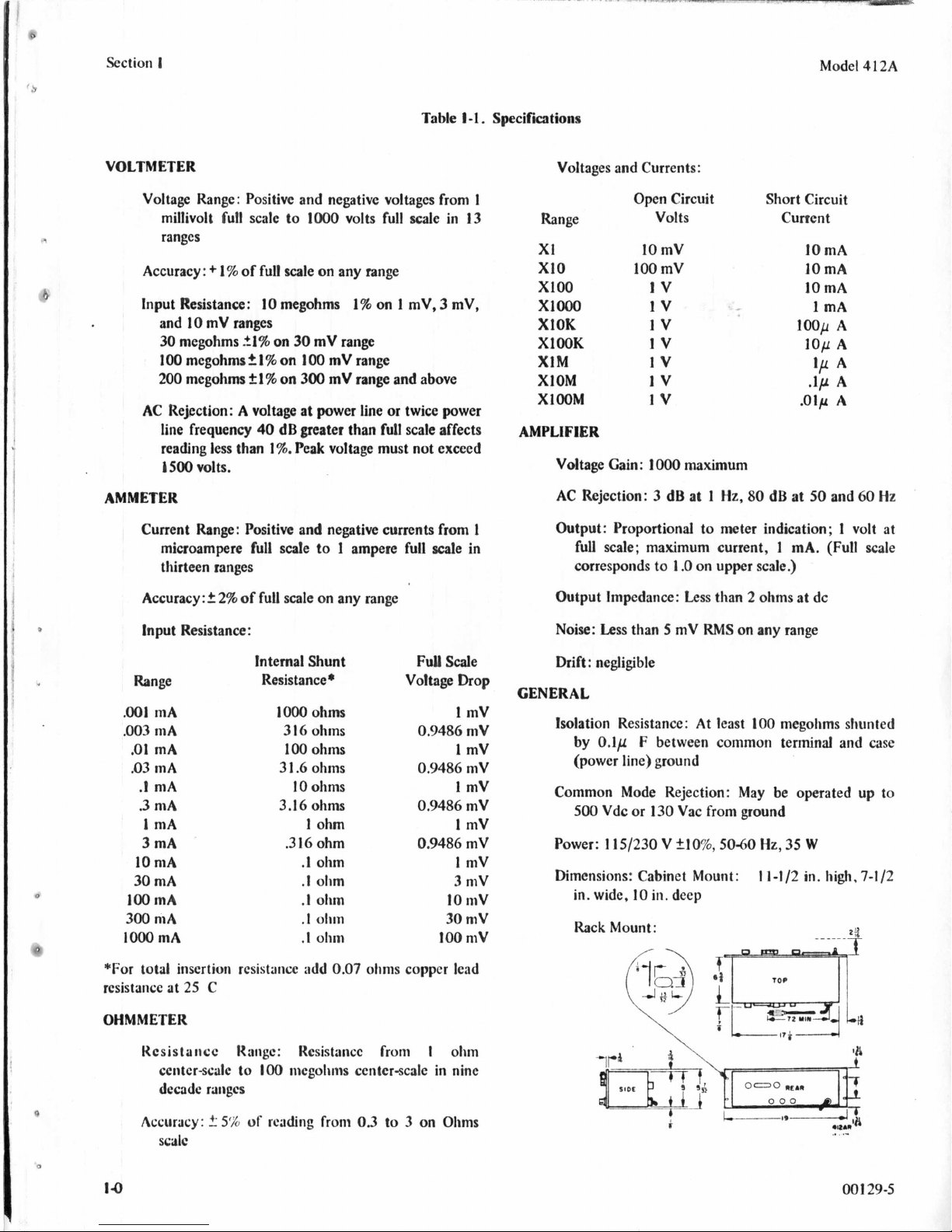
1-1.
Voltage Range: Positive and negative voltages from
millivolt
ranges
Accuracy
Input Resistance:
and
30
100
200
AC Rejection: A voltage at power line
line frequency
reading
1500
fuull
scale to
:
+
1
%
of full scale on any range
10
10
mV ranges
megohms
21%
megohmsf.l%
megohms
less
t
40
than
1
volts.
1000
volts full scale in
megohms
on
30
on
100
%
on
300
dB
greater
1%.
Peak voltage must not exceed
1%
on 1 mV, 3 mV,
mV range
mV range
mV range and above
or
twice power
than full scale affects
Specifications
1
13
AMPLIFIER
Voltages and Currents:
Open Circuit Short Circuit
Range
XI
XI0
XI00
XlOOo
XlOK
XlOOK
XIM
XlOM
Xl00M
Voltage Cain:
AC
Rejection: 3 dB at
Volts
10
mV
100
mV
IV
1v 1
1v
1v
1v
1v
1v
1000
maximum
1
Hz,
80
Current
100~
.Olp
dB at
Model
10
mA
10
mA
10
mA
mA
lop
'P
.lp
50
A
A
A
A
A
and
4
60
12A
Hz
d
Current Range: Positive and negative currents from
1
microampere full scale to 1 ampere full scale in
thirteen ranges
Accuracy
v
tnput Resistance
Range Resistance* Voltage
:
2
2% of full scale on any range
:
tnternal Shunt Full
Scale
Drop
Output: Proportional
full scale; maximum current,
corresponds to
Output Impedance:
Less
Noise:
than 5 mV
Drift: negligible
to
meter indication; 1 volt at
1
.O
on upper scale.)
Less
than 2 ohms at dc
RMS
on
1
mA.
any range
(Full
scale
GENERAL
.001
mA
.003
mA
.01
mA
.03
mA
.I
mA
.3
mA
1
mA
3
mA
10
mA
30
mA
100
mA
300
mA
1000
mA
*For
total insertion resistance add
25
rcsistance at
C
I000
3
I6
100
3
I
.6
IO
3.16
.3
ohms
ohms
ohms
ohms
ohms
ohms
1
16
.1
.I
.I
.I
.I
ohm
ohm
ohm
olim
olim
ohin
ohm
0.07
1
mV
0.9486
0.9486
1
mV
mV
mV
1 mV
0.9486
0.9486
10
30
100
mV
1
mV
mV
1
mV
3
mV
mV
mV
mV
ohms copper lead
Isolation Resistance: At least
by 0.1~
F
between common terminal and case
100
megohms shunted
(power line) ground
Common Mode Rejection: May be operated up to
500
Vdc
or
130
Vac from ground
f10%,
5040
Hz,
35
11-1/2
W
in. high,
7-1/2
Power: 115/230 V
Dimensions: Cabinet Mount:
in. wide,
10
in. deep
Rack Mount:
OHMMETER
Hesistaticc Ibiige: Rcsistancc from
center-scale to
raiiges
decade
a
Accuracy:
f-
5%
of
IO0
niegolims center-scale in nine
reading froni
scale
'I
14
0.3
to 3 on Ohms
I
olim
001
29-5
Page 6
Model
4 12A
Section
I
SECTION
GENERAL
1-1.
INTRODUCTION.
1-2.
The Hewlett-Packard Model
Tube Voltmeter is
a
multifunction instrument which
measures the entire range
resistance normally encountered in electronic equipment.
1-3.
The Model
mV full scale to
arranged in a
of
full scale. The input circuit
from
power line ground.
14.
The Model
current from
accuracy
3,
1-5.
412AIAR
of
10
sequence.
Resistance measurement capability
is
2%
from
412AIAR
IO00
V full scale in thirteen ranges
1,3,
10
sequence. Voltmeter accuracy is
412AlAR
1.OpA
of
full scale. Current ranges are also in a
1.0
measures positive
full scale
ohm center scale
412A/AR
of
dc voltages, current, and
DC
Vacuum
measures dc voltage from
is
isolated from the case and
or
negative dc
to
1.0
A
full scale with an
of
the Model
to
I00
megohms
1.0
1%
1,
I
INFORMATION
center scale in nine decade rangcs. Resistaiicc nieasureiiieiit
is
5%
accuracy
16.
The Model
between
voltage proportional to the input. Ainplificr giiiil is froiii
-1000
to
t1000,
depending on range selected.
1-7.
SPEC1
FlCATlO NS.
1-8.
Complete specifications
are listed in Table
1-9.
INSTRUMENT AND MANUAL IDENTIFICATION.
1-10.
Hewlett-Packard uses a twoscctioii cigltbdigit scrial
number
number
(OOO-00000).
of
your instrumcnt do not agrcc witti thosc
title page of this manual, changc sliects supplicd
will
manual
explain the diffcrenccs bctwccii
instrument and the Model
manual.
'
.3
and
3
412AIAR
1-1.
If
has a dc aiiiylifier output
for
the first tlircc digits
412AIAll
on
the resistance scale.
the dip- Modcl41
of
dcscribcd
2AIAR
tlic
scrial
on
tlic
with
tlic
your
in
lliis
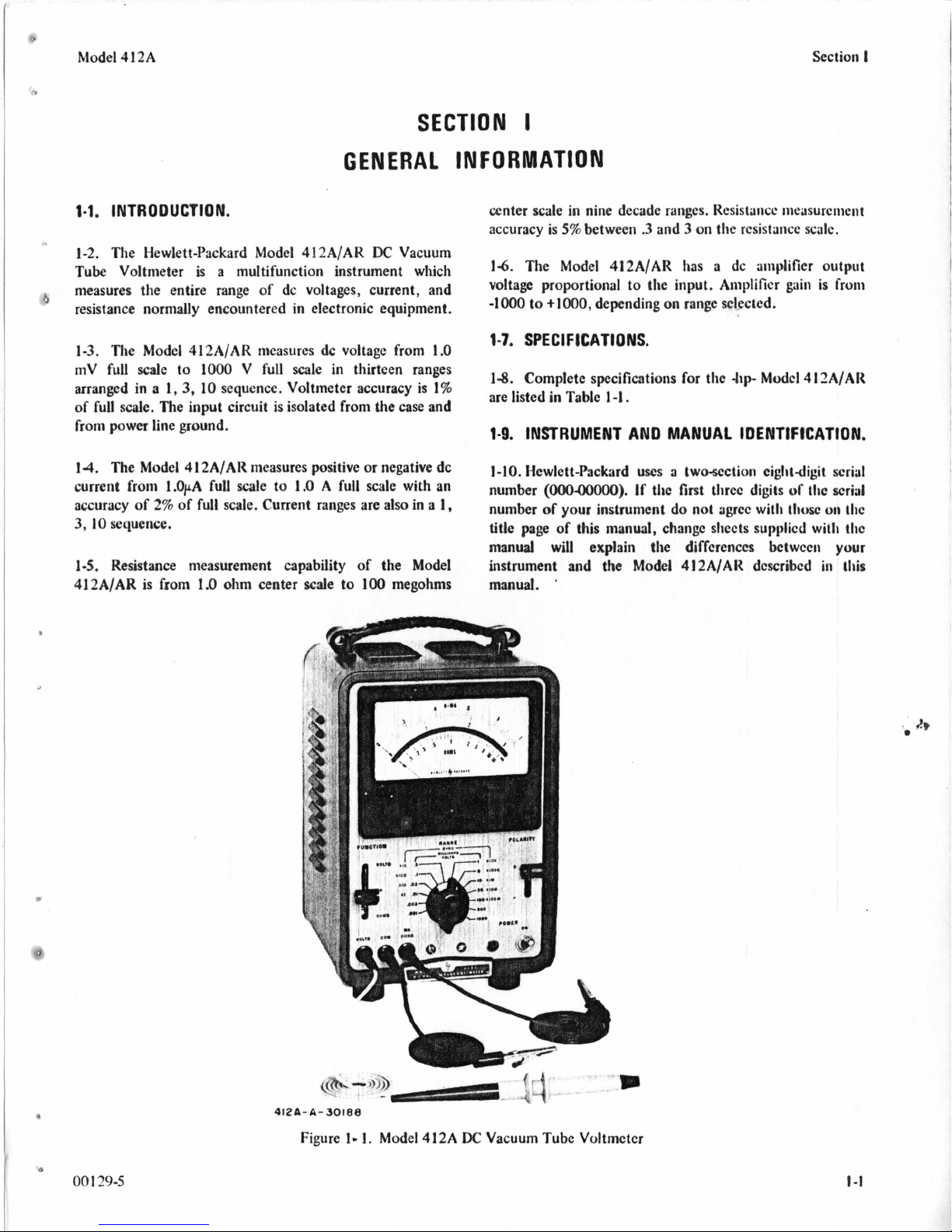
412A-A-30188
Figure
00
1
295
1.1.
Model
412A
DC
Vacuum Tube Voltmctcr
Page 7
0
Model 4 12A
h
Section
I1
2-1.
INTRODUCTION.
2-2. Tliis section contains instructions necessary for
installation
the Model 412AIAR
DC
Vacuum Tube
of
Voltmeter. Included are initial inspection procedures,
cy
power and grounding requirements, installation
information, and instructions for repackaging for shipment.
2-3.
INITIAL INSPECTION.
2-4.
This
instrument was carefully inspected both
and
mechanically
of
free
mars or scratches, and in perfect electrical order
upon receipt.
inspected for physical damage
clcctrical
procedure outlined in Paragraph
electrically before shipment. It should be
To
confirm this, the instrument should be
in
transit.
performance
of
tlic instrument, using the
5-5.
If
there is damage or
Also
deficiency, see tlic warranty on the inside front cover of
this manual.
2.5.
POWER
2-6.
P
Y
The Model 412AIAR can be operated from any
source
slide switch
Power dissipation is approximately
REQUIREMENTS.
of
115
or
230
on
the rear panel selects the desired voltage.
volts at
50
or
35
60
Hz.
watts.
The
SECTION
IN
STACLATIO
test the
115/230
V
II
N
2-1
0.
INSTA 1 LATlO N.
2-1
I.
The Model 412A is intended
instrument, having a top-mounted handle and rubbcr fcct.
2-12. The Model 412AR is intended for rack mounting.
Front panel height
2-13.
REPACKAGING
2-14.
The following paragraphs contain a general guidc for
repackaging
the original container is
is
5-7/32 inches.
FOR
SHIPMENT.
of
tlie instrument. Rcfcr to Paragraph
to
be
uscd;
have any questions, contact your
Service Office. (SCC Appendix
B
NOTE
If
the instrumcnt is to be sliippcd
I
Icwlctt-i’ackard for scrvicc
attach a tag to tlic instrumcnt idcntifying
the owncr and indicating tlic scrvicc
repair
to
be accomplislicd. lncludc tlic
model number
of
tltc instrumcnt.
corrcspondcnce, identify tlic instrumcnt
by modcl numbcr, scrial numbcr prcfix,
and scrial numbcr.
for
use
as
a
2-16
if
it
is
not.
local
-lip-
Salcs
for office locatiwis.)
to
or
repair.
or
In
any
bcncli
2-15
If
you
and
if
G
R
0
U
N
D
I
NG
2-7.
2-8.
To protect operating personnel, the National
REQUl
Electrical Manufacturer’s Association
that tltc instrument panel and cabinet
R
EMENTS.
(NEMA)
recommends
be
grounded. This
instrument is equipped with a threeconductor power cable
wluch, when plugged into an appropriate receptacle.
on
grounds the instrument. The offset pin
the connector is
tlie ground wire.
2-9.
To
preserve the protection feature when operating the
instrument from a twocontact outlet, use a threeprong
4b
two-prong adapter and connect the green pigtail
adapter to ground.
NOTE
Operating the Model 412A/AR without
grounding the third (power line ground)
wire
of
the power cable will result
of
the meter and oscillation
1
29-5
zero offset
the pointer.
4
J
00
in
of
2-15. Place the instrumcnt
suitable packing material and
metal bands.
be
purchased from your ncarcst
If
original containcr
in
original conhincr with
scat
wcll
with strong tapc
is
not aviilablc, onc
hp
Salcs
and
or
CBR
Scrvicc
Office.
2-16.lf original container
is
not to hc uscd, procccd
as
follows:
a. Wrap instrument
in
hcavy
papcr or plastic hcfurc
placing in an inncr containcr.
to
on
the
b.
Place packing material around a11
instrumcnt and protcct panel facc
strips
.
with
c. Place instrument and inncr containcr
carton
tapc
or
wooden box and scal wcll with strong
or
metal hands.
sidcs
of
cardhturd
in
a hcavy
a
d. Mark shipping containcr
INSTIWMENT,”
“FRAGILE,” ctc.
“DI~LICATE
2-1
Page 8
hlodcl4
12A
Section
111
SECTION
0
PER
AT1
N
G
3-1.
INTRODUCTION.
3-2.
The
-lip-
Model 412A/AR
Voltmeter nieasures dc voltages from
full
lo00 V
Current measurement ranges are from
1000
to
The Model
1.0
ohm center
Resistance measurenicnt accuracy is
.3
and
provided.
+1000,
1
.O
V
at full scale. and maxinium current load is
3-3.
LOW-LEVEL ELECTRICAL PHENOMENA.
34.
Stray low-level electrical phenomena may cause error
in
low voltage measurements. When using the lower voltages
of the Model 412A, consider the possibility
voltages produced by thermoelectric effects, residual
charges on capacitors, battery action,
cables,
scale with
mA
full
scale, with accuracy
41
2A/AR makcs resistaricc measurements from
3
on
the ohms scale. A dc amplifier output is also
Voltage
depending
an
accuracy of
scale
to
100
gain of tlic amplificr is from
on
range selcctcd. Amplifier output is
DC
Vacuum Tube
1.0
mV full scale to
1%
of
full
scale.
0.001
mA
full
scale
of
2%
of
full scale.
megohms center scale.
5%
of
reading between
-1000
to
1
.O
mA.
of
low-level
or
flexing
of
coaxial
IN
STRU
3-7.
3-8.
111
CTiO
TURN-ON PROCEDURE.
a. Make sure the proper fuse is installed for operation
with the power line voltage to be used. A
slow-blow fuse should be used for
operation, and a
operation.
b. Connect
Allow
VOLTAGE
NS
BEFORE CONNECTING PRIMARY
POWER, MAKE SURE THE REAR
PANEL 115/230 V SLIDE SWITCH
IS
SET
TO
THE POWER LlNE
VOLTAGE
INCORRECT SETTING MAY
RESULT IN DAMAGE TO THE
INSTRUMENT.
to
ac power and turn instrument ON.
a
S-minute warm-up period.
MEASUREMENT.
TO
BE
0.4
A slow-blow fuse for
USED.
0.6
I
IS
230
A
V
V
3-5.
The voltagc probe, currentlresistance lead, and
common lead
have a very low thermoelectric effect with copper, the most
commonly used conductor. However, some component
leads such as transistors and reed relays may have leads
of
made
thermoelectric voltage when joined with copper. Whenever
possiblc, connect tlic
possible, the voltage probe and common lead should both
In:
conncctcd
and both connection points maintained at the same
tc
111
pcra
34.
To minimize tlic possibility
making
probe tip and common lcad alligator clip are clean.
surc
tlic component leads or other points of connection are
clean. The prcsence
niay cause noticeable nieasiirement error due to battery
action.
of
the Model 412A/AR are all designed to
such alloys as nickel-iron, which produce a
412A
leads to copper. If this
to
the
smic
kind
of
inctal compncnt lead,
t
urc.
of
battery action when
low
voltage mcasurcments, make sure the 412A
Also
of
sonic chemicals such
NOTE
Operating the Model 412A/AR without
grounding the third (power line ground)
of
wire
zero offset
the pointer.
the power cable will result in a
of
the meter and oscillation
as
solder flux
of
is
not
be
a.
Set
FUNCTION switch to VOLTS, and select
proper polarity.
b. Set RANGE switch to desired range.
set
switch to high range and downrange as
necessary.
c.
Connect VOLTS and
component, and read voltage.
DO
NOT OVEKLOAD THE
INSTRUMENT. MOMENTARY
OVERLOADS UP TO TEN TIMES
FULL SCALE WILL NOT DAMAGE
THE INSTRUMENT; HOWEVER,
CURRENT SHUNTS, AND
INTERNAL RESISTANCE
STANDARDS ARE NOT
PROTECTED FROM EXTREME
OVERLOAD.
33.
CURRENT MEASUREMENT.
a. Set FUNCTION switch to
b.
Set RANGE switch to desired range.
select high range and downrange as necessary.
COM
If
in doubt,
leads across circuit
MA.
If
in doubt,
or
00
1
29-5
3-1
Page 9

section
.
3-10.
111
c. Deenergize circuit
d. Connect
COM leads.
e.
Energize circuit,
up-scale indication, and read current.
When making current measurements,
make
the circuit common
ground (&)terminals on rear panel.
RESISTANCE
a.
Set
FUNCTION switch
b.
If resistance
make sure
c.
Connect
measured, using
to
412A
into circuit,
NOTE
sure
there
is
no connection between
MEASUREMENT.
to
be
power
is
412A
across circuit
MA/OHMS
be
measured.
set
POLARITY
6)
and power line
to
OHMS.
measured
turned
off.
and COM leads.
using
MA/OHMS
switch
is
part of a circuit,
or
component
to
and
for
be
Model
41
2A
d.
Set
RANGE switch
near center scale as possible, and read resistance on
OHMS
scale.
3-1
1.
When measuring the resistance
such as transistors and diodes, it is often desirable
what voltage and current were present in obtaining the
resistance measurement. Table
voltage and shortcircuit current available at
during resistance measurements. Voltage and current are
read on the top scale
The meter reading is directly proportional
across the device being measured, and inversely
proportional
device being measured on the
.25
on
the
top
100
mV (Table
across the device. To determine the current, subtract the
meter reading
multiply by the shortcircuit current listed in Table
Since the current shown
indicates
measured. The resistance measurement, then, indicates an
equivalent resistance
20
mV, and a current
of
to
the resistance scale. The meter
scale. Since full-scale voltage for the
a
current
of
the current.
34),
of
.2
from the full scale reading
of
of
so
that meter indication is as
of
non-linear devices
3-1
lists the open-circuit
the
412A
the meter
this indicates a voltage
for
all
resistance ranges.
to
the voltage
As
an example, assume that
XI0
range gives a reading
also
indicates
XI0
of
of
for
the
XI0
range
is
10
8
mA through the device being
2.5
ohms, with an applied voltage
of
8
mA.
to
know
leads
.2
range is
20
mV
1,
and
3-1
mA,
this
a
of
on
.
Resistance Range
XI
XI0
XI00
X1
K
XlOK
XlOOK
XIM
XlOM
XlOOM
Table
3-1.
Voltage and Current in Resistance Measurements
1
OpenCircuit Volts
1
on top scale)
(at
10
mV
100
mV
IV
1v
1v
IV
IV
1v
1v
ShortCircuit Current
0
on tot, scale)
(at
10
mA
10
mA
10
mA
1
mA
l00pA
IO
pA
lPA
0.1
pA
0.01
pA
3-2
00
1
29-5
Page 10
Model
4
12A
Section
111
3-12.
AMPLIFIER OPERATION.
3-13.
The Model
used to drive devices
permanent record
4
412A/AR
such
of
measurements. Output level is
DC
Amplifier Output may be resistance) may cause errors in meter indication and
as an analog recorder to provide a amplifier
1
.O
volt range
at full scale; maximum rated load current is
currents
to
in
excess
of
1.0
gain.
Amplifier gain is from
-1000
on the
loo0
mA (less than
+lo00
range.
1000
1
.O
mA.
ohms load
on the
Load
,001
Y
00 1 29-5
I‘
3-3
Page 11
Model
41 2A
Section
1V
SECTION
THEORY
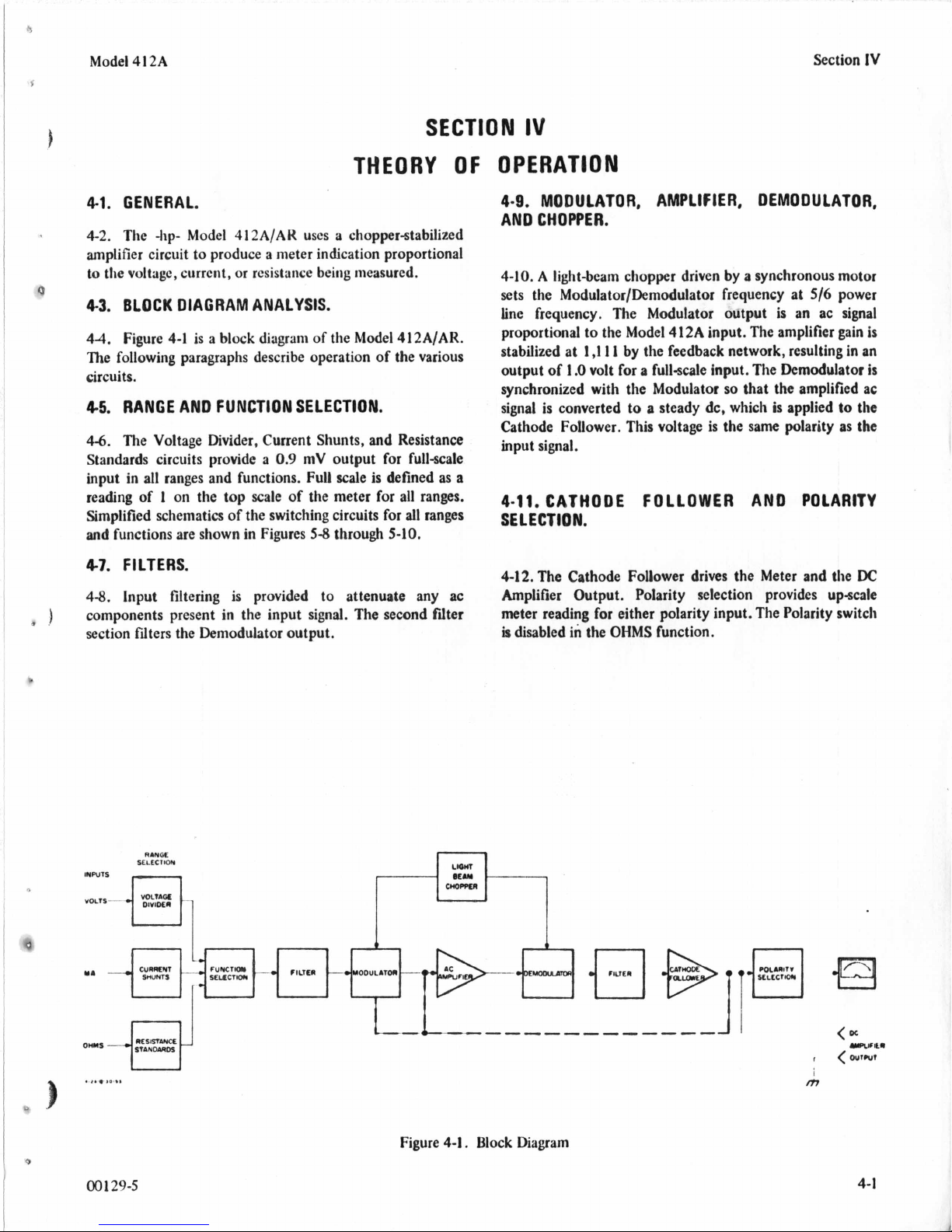
4-1.
GENERAL.
4-2.
The kp- Model
amplifier circuit to produce a meter indication proportional
to the voltage, current, or resistance being measured.
4-3.
BLOCK
44.
Figure
The following paragraphs describe operation of the various
circuits.
4.5.
RANGE AND FUNCTION SELECTION.
4-6.
The Voltage Divider. Current Shunts, and Resistance
Standards circuits provide a
input in all ranges and functions. Full scale
reading
Simplified schematics
and
functions are shown in Figures
47.
FILTERS.
4-8.
input filtering is provided to attenuate any ac
components present in the input signal. The second fdter
section filters the Demodulator output.
DIAGRAM ANALYSIS.
4-1
of
1
on
412AIAR
is
a block diagram
the top scale of the meter for all ranges.
of
the switching circuits
uses a chopper-stabilized
of
the Model
0.9
mV output for full-scale
5-8
through
412AIAR.
is
defined as a
for
all ranges
5-10,
OF
IV
OPERATION
4-9.
MODULATOR, AMPLIFIER, DEMODULATOR,
AN0
CHOPPER.
4-10. A
sets the Modulator/Demodulator frequency at
line frequency. The Modulator output is an ac signal
proportional
stabilized at
output
synchronized with the Modulator
signal
Cathode Follower. This voltage is the same polarity as the
input signal.
4-11.
SELECTION.
4-12.The Cathode Follower drives the Meter and the
Amplifier Output. Polarity selection provides upscale
meter reading for either polarity input. The Polarity switch
is disabled in the
light-beam chopper driven by a synchronous motor
516
power
to
the Model
1
,111
of
1
.O
volt for a full-scale input. The Demodulator
is
converted to a steady dc, which
CATHODE FOLLOWER AND POLARITY
412A
input. The amplifier
by the feedback network, resulting in an
so
that the amplified ac
is
applied
gain
to
the
is
DC
OHMS
function.
is
RANOC
SELtCllOW
00
129-5
r
Figure
I
4-1.
Block Diagram
4-1
Page 12
6
Section V
INSTRUMENT
DC
Voltage Standard
Variable Line Transformer
DC
Voltmeter
AC
Voltmeter
~ ~ ~~
Oscilloscope
TYPE
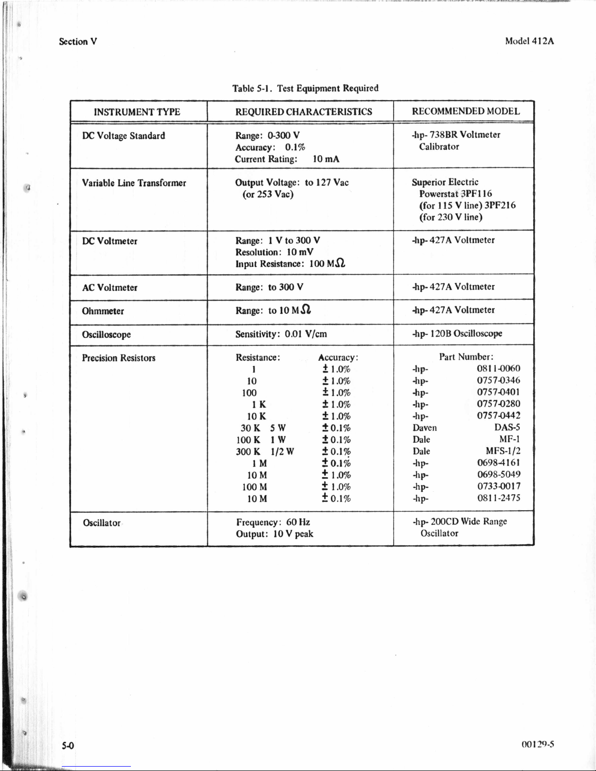
Table
5-1.
Test Equipment Required
REQUIRED CHARACTERISTICS
Range:
Accuracy:
Current Rating:
Output Voltage:
Range:
Resolution
Input Resistance:
Range: to
Range: to
Sensitivity:
(or
253 Vac)
0-300V
0.1%
1
V
to
300
:
10
mV
300
V
10
Ma
0.01
10
to
127
V
100
Vlcm
mA
Vac
Ma
hp- 738BR Voltmeter
Calibrator
1
Superior Electric
Powerstat 3PF116
(for
1
15
V line) 3PF216
V
(for 230
hp- 427A Voltmeter
hp-
427A Voltmeter
hp- 427A Voltmeter
hp
120B
line)
Oscilloscope
Model 412A
Precision Resistors
Oscillator
Resistance:
1
10
100
1K
10
30K
100K
300
K
1M
10
100
10
-~
~
Frequency : 60 Hz
Output:
K
M
M
M
5W
1W
1/2
W
IO
V peak
Accuracy
i
1.0%
2
1.0%
f
1.0%
f
1.0%
+,
1.0%
?
0.1%
2
0.1%
2
0.1%
2
0.1%
2
1.0%
2
1.0%
k
0.1%
:
Part Number:
-hP-
-hP-
hP-
-hp-
-hP- 07574442
Daven
Dale
Dale MFS-112
-hP
-hP
-hP-
-hP-
-hp-
200CD Wide Range
Oscillator
08
1
I-OoFiO
07574346
0757.040
07574280
1
DAS-5
MF-I
06984 16
0698-5049
0733401
08
1
1-2475
1
7
Page 13

Model 4 12A
Section
V
SECTION
MAINTENANCE
5-1.
INTRODUCTION.
5-2.
This section contains information necessary to
maintain the kp- Model 412A/AR. The following
paragraphs describe the Performance Checks, Calibration
Procedures, Troubleshooting, and Servicing Procedures.
5-3.
REQUIRED TEST EQUIPMENT.
54.
Recommended test equipment for maintaining and
of
checking performance
5-1.
Test
instruments other than those recommended may
be
used if their specifications equal
characteristics.
55.
PERFORMANCE CHECKS.
5-6.
Use
the following procedures to verify proper
operation of the Model 412A. The 412A and test
equipment should
otherwise specified. A Performance Test Card is provided at
the end of this section for recording the performance of the
Model 412A. The card may
and used as a permanent record
or
of
a routine performance check. If the Model 412A does
not meet specifications at
5-1
to Paragraph
5-7.
METER
5-8.
The meter pointer should rest over the zero
calibration mark when the instrument is at normal
operating temperature, is turned off, and is in the normal
operating position.
mechanical adjustment procedure outlined in Paragraph
8
before proceeding with the performance checks.
5-1
5-9.
Turn the Model 412A POWER switch ON. After a
5-minute warm-up period, the meter pointer should rest on
zero
when the input leads are shorted. If not, perform the
electrical zero adjustment outlined in Paragraph 5-22.
Operating the Model 412A/AR without
grounding the third (power line ground)
wire of the power cable will result in a
zero offset of the meter and oscillation
the printer.
5,
ZERO.
the Model 412A is listed in Table
or
exceed the required
be
operated at 115/230 Vac unless
be
removed from the manual
of
the incoming inspection
any
point in this procedure, refer
Adjustment and Calibration procedure.
If
the pointer is off
NOTE
zero,
perform the
of
V
5-10.
VOLTMETER ACCURACY CHECK.
a. A dc voltage standard and a variable line
for
transformer are required
Model
should be allowed a 30-minute warm-up period.
b. Connect 412A
line voltage switch (1
voltage being used. Turn 412A ON and allow
5-minute warm-up period.
c.
Set 412A FUNCTION to VOLTS, POLARITY to
738BR Voltmeter Calibrator is used, it
to
variable line transformer, and set
15/230)
+.
d. Connect VOLTS and COM leads to dc standard
out put.
e.
Check 412A indication against dc standard output
on
at full scale
should be
small division
When checking the Modcl 412A
the .001 and
off the dc standard output and note
any 412A
thermoelectric voltage. Add
subtract
the 412A reading.
f. Check 412A meter tracking
cardinal points on the meter scale. Maximum crror
should be no greater than
polarity input.
g. Repeat step e on
and I27 volts
5-11.
MILLIAMMETER ACCURACY CHECK.
a. A dc voltage standard and the prccision rcsistors
listed in Table
b. Set 4 12A FUNCTION to MA. I’OLARITY to
each 412A range. Maximum error
no
greater than
on
top scale).
NOTE
.003
zero
as
necessary any offset from
.
1
V
(or
207 and 253 V).
5-2
rcquircd
this chcck.
to correspond to line
f
1%
of full scale (one
volt ranges, turn
offset due
on
the 1 V rang at
0.01
V
range at line voltages of
for
this chcck.
If
an -tip-
on
to
or
all
with cithcr
103
+.
001
29-5
5-1
Page 14
Section
V
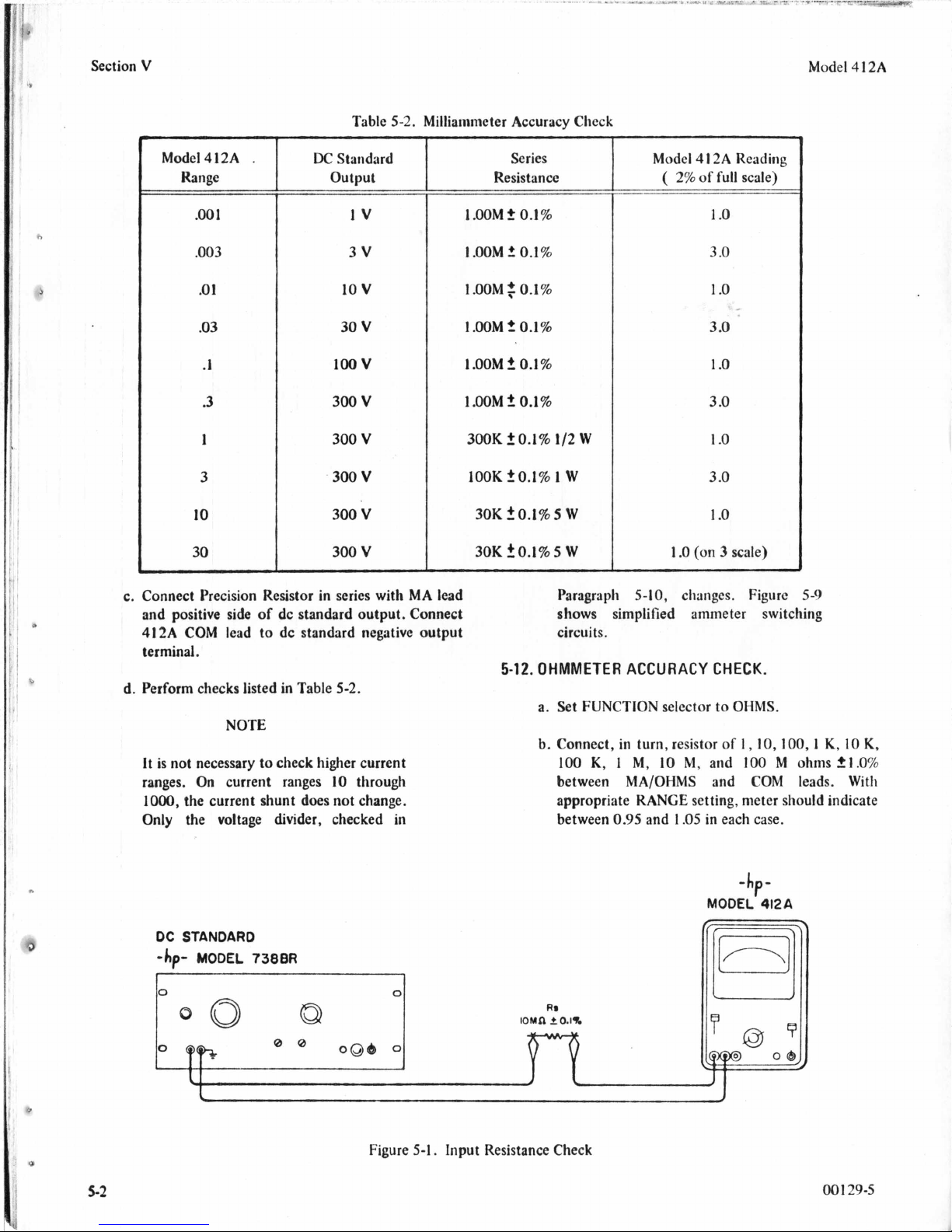
Table
5-2.
Milliammeter Accuracy Check
Model
4
12A
DC
Standard
3
Range
.O
1
.03
.I
.3
1
3
IO
30
c.
Connect Precision Resistor in series with MA lead
of
and positive side
412A
COM lead to dc standard negative output
terminal.
d. Perform checks listed in Table
dc standard output. Connect
output
IV
3v
10
v
30
V
100
v
300
v
300
V
300
V
300
V
300
V
5-2.
NOTE
It is not necessary
ranges.
1000, the current shunt does not change.
Only the voltage divider, checked in
On
to
check higher current
current ranges
10
through
Series
Resistance
I.00M
t
0.1%
1
.OOM
t
0.1%
1.00M~O.I%
1
.OOM
2
0.1%
I
.OOM 2 0.1%
1.00M?
300K
lOOK
30K
30K
5-12.
0.1%
iO.l%
20.1%
2
to.]%
1/2
1
0.1%
5
5
Paragraph
shows simplified ammeter switching
circuits.
OHMMETER
a.
Set
b. Connect, in turn, resistor
100
between MA/OHMS and COM leads. With
appropriate RANGE setting, meter should indicate
between
W
W
W
W
ACCURACY
FUNCTION
K, 1 M,
0.95
Model
5-10.
and
4
1
2A Reading
(
2%
of full scale)
1
.o
3
.O
1
.o
3
.O
1
.o
3
.O
1
-0
3
.O
1
.o
1
.O
(on
3
scale)
changes. Figure
CHECK.
selector
10
to
M,
and
1.05
in each case.
OHMS.
of
1,10,100,1
100
5-9
K,
M
ohms+I.O%
10
K,
DC
STANDARD
-hp-
MODEL
738BR
I
5-2
I
Figure
5-1.
Input Resistance Check
-hp-
MODEL
~
412A
001
29-5
Page 15

J
Model 4
5-13.
i
h
12A
INPUT RESISTANCE
a.
Connect the Model 412A/AR, dc standard and
rnegolim resistor
b.
Set 412A
FUNCTION
CHECK.
as
shown
to
in
.Figure
VOLTS,
5-1.
POLARITY to
+.
c. Adjust
voltages listed in Table
reading in each case verifies the input resistance
where:
412A
Table
RANGE and dc standard output to
5-3.
A
correct meter
=
Eapplied
Ein
5-3.
Input Resistance Checks
412A
Reading
5.0
[
&&]
Meter
(?
1
%)
mV
1
412A
'
Resistance
IOMQ
Input
10
c. Set ac voltmeter FUNCTION
RANGE to
d. Adjust oscillator frequency to
output for an indication
voltmeter. This corresponds
noise signal at the
e. The 412A meter rcadingshould
division
5-15.
ADJUSTMENT AND CALIBRATION
5-16.
The following proccdures should bc pcrfornicd
it has been determined by the Performance Chccks outlincd
in
Paragraph
specifications.
5-17.
CABINET REMOVAL.
a. Disconnect power cord from powcr source.
IO
V.
on
upper scale)..
5-5
that the Model
412A
input.
412A/AR
to
60
of
to a IO
be
AC
Hz,
7.07
02
Section
and adjust
V
V
I%(l
V
VOLTS,
on
ac
pcak
;IC
minor
PROCEDURE.
only
if
docs
not
iiicct
22.5
mV
100
mV
9
5-14.
AC
c
D
REJECTION
a.
Connect the Model
voltmeter as shown in Figure
b.
Set 412A FUNCTION to
+,
and RANGE to
OSCILLATOR
hp
200CD
90.9
0.95
CHECK.
412A/AK,
0.1
V.
mV
V
5-2.
VOLTS,
30
Ma
100
Ma
200
Ma
oscillator, and ac
POLARITY to
MODEL
-hp-
b.
On cabinet model, rcmovc two rctaining
near center of rear panel. On rack modcl, rciiiovc
in
rcar
of
three retaining screws
c.
Slide instrument chassis forward
5-18.
MECHANICAL ADJUSTMENT
5-19.
If
mechanical zero
over the zero calibration mark
instrument is at normal opcrating tcmpcraturc,
normal operating position, and turncd
zero is not corrcct, perform thc following adjuslment
procedure.
412A
of
mctcr is corrcct, pointcr rcsts
covcr.
out
OF
METER
on
thc nwtcr scalc wlicii
off.
scrcws
of
cabinct.
ZERO.
in
If
nicclianical
its
J
b
001
29-5
Figure
5-2.
AC
Rejection Check
5
-3
Page 16

J
19
Section
V
10,
*7
3.
C
Model
4
I
2A
R46
METER
CAL
-
-
4
-
R126
HUM
BAL
CAL
R126
HUM
BAL
n
GAIN
CAL
Figure
5-3.
Location
of
Adjustments
00
I
29-5
Page 17

Model
4
12A
a. Turn 412A ON and allow a 20-minute warm-up
period. This
normal operating tcniperaturc.
allows
meter movement
to
reach
5-22.
METER ELECTRICAL ZERO ADJUSTMENT.
NOTE
Section
V
30
b. Turn instrumcnt OFF and allow
capacitors
c.
Rotate mechanical zero-adjustment screw
clockwise until meter pointer is to left of zero and
moving upscale toward zero.
d. Continue to rotate adjustment screw clockwise
and stop when pointer
If pointer overshoots zero, repeat steps
e. With pointer exactly on zero, rotate adjustment
screw counterclockwise approximately
This frees adjustment screw from meter
suspension. If pointer moves during this step,
repeat steps
5-20.
HUM BALANCE ADJUSTMENT.
a. Turn
period.
b.
Set FUNCTION
c.
Connect oscilloscope to
OUTPUT.
d. Adjust HUM BAL (R126, Figure
minimum
line frequency is
8-1/3
to
discharge.
c
through e.
412A
ON and allow 5-minute warm-up
to
10
Hz
signal
Hz instead of
is
exactly over zero mark.
VOLTS.
on
oscilloscope. (If power
50
Hz, beat frequency will be
10
Hz.)
seconds for all
DC
AMPLIFIER
c
and d.
10
degrees.
5-3)
for
Meter electrical zero adjust circuit
may not
model instruments with serial
number 424-14482 and below, or
41
serial number 424-1 5082 and below.
a. Turn 412A ON and allow
period.
b. Set FUNCTION
c.
Short VOLTS probe
d. Adjust ZERO ADJ (R129) for zero dcflcction of
the meter pointer. Check the zcro adjustmcnt by
switching POLARITY from
adjusted properly, this action should produce a
minimum amount of deflection.
5-23.
AMPLIFIER
B R AT1
0
CALI
a.
b.
c.
N
A
dc standard and a de voltmeter arc rcquircd for
these adjustments.
Connect 4 12A VOLTS probe and COM lcad
standard output.
RANGE
Connect dc voltmeter betwccn dc standard output
(t)
and 412A
be
installed in 412A cabinet
2AR rack mount instruments with
a
30-minute warm-up
to
GAIN
VOLTS, RANGE
to
COM lead.
t
ADJUSTMENT AND METER
to
-
to
When zero
.
Set
FUNCTION
to
1
V,
POLARITY to
DC
AMPLIFIER OUTPUT liigli.
t.
in
.001.
to
is
to
dc
VOLTS,
NOTE
The Hum
the 120
minimum 10
With the VOLTS lead shorted
COM
the 412A meter will show a
minimum deflection when the Hum
Bal.
5-21.
CATHODE FOLLOWER BIAS ADJUSTMENT.
a.
Set
412A
beyond 1000).
b. Adjust rear panel BIAS
pointer approximately on zero. This adjustment is
not critical, since
reduced more
switch is in any operating position.
00
129-5
Bal.
control docs not affect
Hz
ripple. Adjust only for
Iiz
(or
8-1/3
lead and POLARITY set
is
correctly adjusted.
RANGE
switch fully clockwise (one step
ADJ
any
deviation from zero is
than
100
times when the RANGE
Hz) signal.
to
(R116)
to
to
t,
set
meter
d.
Set
dc standard output to
e.
Adjust 412A GAIN
indication on test voltmctcr.
test voltmcter indicates
calibration.
f. Adjust METER CAL (R46) to sct 412A meter
1.0
pointer on
voltmctcr.
g.
Chcck 4l2A calibration at full scalc on all ranges
as outlined
error morc than
to
bring
all
5-24.
OHMMETER ADJUSTMENT.
a. Set 412A FUNCTION to OIIMS, ItANGIi to
Make ccrtain
connected through wmc cxtcrnal rcsistancc.
on top scale. Disconnect test
in
Paragraph
I%,
readings within
MA/OlIMS
+I
CAL
1%
5-10.
rcadjusl
f
1
and (:OM
V.
(RI
19)
A
10
mV rcading
crror in 4 12A gain
If
any rcading
GAIN
CAL
X.
lcads
for zcro
on
is
in
(It1
19)
XI
K.
are not
5-5
Page 18

Section
V
Model 4 12A
b. Adjust rear panel OHMS ADS (R36) for meter
indication
(corresponding to
1.0
on upper
of
aD
scale).
525.
TROUBLESHOOTING.
5-26. When the Model 412A/AR operates improperly, first
to
adjust and calibrate it according
5-15.
If
in Paragraph
calibration
the procedures outlined
is
not possible, procecd
with the troubleshooting steps.
CONTAMINATION OR
FINGERPRINTS ON THE RANGE
OR
SWITCH
MOUNTED
THE COMPONENTS
ON
THE RANGE SWITCH
MAY REDUCE ACCURACY OF
INSTRUMENT.
5-27.
FRONT
5-28.
If the malfunction is common
PANEL INDICATIONS.
to
all
ranges and
functions, the trouble may be in the amplifier or power
supply areas. If the instrument operates improperly on only
or
one range
function, the trouble
switching section
5-29.
POWER SUPPLY
or
input cables.
AND
AMPLIFIER CHECKS.
is
probably in the
5-5.
Table
Tube Iteplaced
VI01 (12AX7) Amplifier
V102 (6AU8) Amplifier/
Cathode Follower
V103 (6x4) Rectifier
V104 (OA2) Regulator
VI05 (OB2) Regulator
5-33.
MODULATOR
a.
An oscilloscope and
CHECK.
for this test.
b.
Disconnect 412A from power source and remove
cabinet.
c.
Remove VlOl and reconnect 412A to power
source.
a
d. Connect
(rear panel
clip lead
BIAS
VOLTS input cable (terminal
Tube Iteplacement
Adjustment
Bal.
Huni
Par.
Gain Cal. Par.
Bias
Adj.
Par.
Cal.
Cain
Par.
None
Ohms Adj.
Par.
-71
a
10
Maresistor are required
from
the center arm
ADJ) to the termination
4
in Figure
5-20
5-23
5-21
5-23
5-24
of
5-7).
R116
of
the
5-30.
Check power supply voltages at points listed in Table
5-4.
Voltages are measured with respect
(A).
Figure
7-2
shows the location
Check Point
53
1.
Tubes are a coinmon source
to
circuit common
of
components.
Voltage
of
trouble and are most
easily checked by substitution. Following replacement
of
in
210%.
particular tube, iiiake the adjustrneiits indicated
5-5.
5-32.
Additional
by
made
of
Note
cliecking
tlic
sclrwutic diagram.
I1
in
checks
voltages shown
Paragraph
of
amplifier operation niay be
Be
sure
7-2.
Allow 3 tolerance
on
the amplifier section
to
observe conditions
of
a
Table
in
e. Set 412A FUNCTION to VOLTS, RANGE to
.001.
f.
Set oscilloscope input to
g.
Connect a
10
DC.
Mfi
resistor in series with
oscilloscope vertical input. Using a clip lead,
connect resistor
junction
of
RlOl and ClOl
to
(input circuit board, Figure 54). Connect
oscilloscope common to 412A COM lead. Set
to
0.2
Vertical Sensitivity
I
Figure
54.
Input
V/cm.
Circuit
Board
5-6
00 1 29-5
Page 19

Model 4 12A
Section
V
h. Turn 412A ON and allow 30-second warm-up
period. Observe de voltage amplitude on
oscilloscope.
i. Move oscilloscopc input (with series resistor) to
Modulator output at junction of green lead from
Modulator and C104
j.
Waveform should be similar
Figure
5-5.
Peak-to-peak amplitude should be
approximately equal
h. Signal frequency sliould be
(0.01
Microfarads).
to
that shown in
to
dc voltage observed in step
5/6
power line
frequency.
k. If waveform is not satisfactory, check chopper
motor and assembly or Modulator and input
circuit as indicated by deficiency in waveform.
p-20
MSEC-
--)1
d. Remove four screws holding light-beam chopper
assembly. It is not necessary to disconnect wires.
e. Spread grip rings on Modulator light rods and slide
rods out
of
Modulator block.
f. Remove four screws holding modulator assembly
to
chassis.
NOTE
Be
sure
to
seat the four insulating
shoulder washers in mounting holcs
when replacing the assembly.
g.
Lift out Modulator assembly. If it is necessary to
replace Modulator block asscmbly only, rcmovc
four screws holding printed circuit board
Note color and location
of
wircs between block
and printed circuit board before disconnccting.
5-36.
DEMODULATOR
a.
Disconnect 412A from powcr sourcc and removc
CHECK.
cabinet.
to
block.
Figure
55.
Modulator Waveform
5-34.
MODULATOR
5-35.
The photoconductor cells in the Modulator
(VllOA/B) are not separately replaceable.
REPLACEMENT.
If
a
cell
is
defective, the Modulator block assembly should be
replaced, using the following procedure.
a. Disconnect 412A from power source and remove
cabinet.
CONTAMlNATION OR
ON
FINGERPRINTS
THE RANGE
SWITCH OR COMPONENTS
ON
MOUNTED
THE RANGE
SWlTCII MAY KEDUCE
ACCURACY
OF
THE
INSTRUMENT.
b.
In 41 2A cabinet model, remove side shield.
c.
Note and record color code of wires before
removing from Modulator assembly printed circuit
board.
b. Remove V102 (on Amplifier Assembly).
c.
On
iight-beam chopper assembly, rcmove uppcr
lamp nearest front of instrument. This
illuminates
d. Connect a
VI
1
I
A.
1.0
microfarad capacitor across input
lamp
terminals of test ohmmeter.
e. Connect test ohmmeter common lead
Demodulator terminal with pinklorange wirc.
Figure
56.
f. Connect other
test
ohmmeter lcad to tcrminal
to
Sec
with whitelorange wire.
g.
Connect 412A
h. Resistance indicated on
to
power source and turn
test
ohmmeter
ON.
should
bc
.
I
to 2 megohms.
i. Turn
j.
41
2A
OFF.
Replace lamp in light-beam chopper and remove
upper lamp nearest rear of instrument. This lamp
VI
illuminates
I 1 B.
k. Connect test ohmmeter common lcad to
Demodulator terminal with brownlorange wirc.
001
29-5
5
-7
Page 20

.
.
,
.
. -.
.
,
.
.
._...
.
..
-
-
..
.,
.
. --*w
”-
b
Section
V
I.
Connect other test ohmmeter lead to terminal
with whitelorange wire.
Model 4 12A
OR FINGERPRINTS MAY KEDUCE
ACCURACY OF INSTRUMENT. IN
ADDITION, LOW ROSIN CONTENT
m.Turn412AON.
SOLDER SHOULD BE USED WHEN
REPLACING COMPONENTS. USE A
I
MINIMUM OF HEAT WHEN
SOLDERING, AND REMOVE TRACES
OF
FLUX
FROM CONNECTIONS. IF
NECESSARY, RANGE SWITCH MAY
BE CLEANED USING A SOLUTION OF
b
Iy
n. Resistance indicated on test ohmmeter should be
to 2 megohms.
0.
Turn
41
2A OFF and replace lamp and
5-37. DEMODULATOR REPLACEMENT.
V102.
MILD DETERGENT AND WARM
5-38.
The photoconductors in the Demodulator are not
cell
separately replaceable. If a
Demodulator assembly should
is defective, the
be
replaced, using the
WATER. RINSE THOROUGHLY IN
DISTILLED WATER AND
DRY
IMMEDIATELY.
following procedure:
a. Disconnect instrument from power source and
remove cabinet.
b.
Disconnect the three wires
5-6
assembly. Figure
shows wire
to
Demodulator
color
codes for
both cabinet (4 12A) and rack (4 12AR) models.
c. Remove four screws holding light-beam chopper.
is
not necessary to disconnect wires.
It
540.If
function, trouble may be in the switching circuits. Either a
component
through
function switching, and may be used to isolate the trouble.
For example, if the instrument operates properly on all
voltage ranges except
contacts may be defective. Figure
components mountcd on the
the malfunction is peculiar to one range
or
switch contact may be defective. Figures
5-10
show simplified schematics of range and
.003;
R1, R9,
rmgc
or
the associated switch
7-3
identifies the
switch.
or
58
5-41.
d.
Remove nuts from four screws holding
.I
Demodulator assembly and remove assembly from
ADJUSTMENT
COMPONENTS.
OF
FACTORY
SELECTED
instrument.
542. R34*.
5-39. SWITCH CHECKS.
5-43.
The value of
R34*
is selected to bring the OHMS ADJ
potentiometer within the proper range, and is dependent
upon the power supply voltage and the value
CLEAN RUBBER GLOVES SHOULD
BE WORN WHEN WORKING ON
THE
RANGE SWITCH. CONTAMINATION
6
resistors in the ohmmeter circuit. Replacement
should not be necessary unless V104 has been replaced
the range switch components have been changed.
VI
of
of
TO
Cl13
TO
AND
TO
RI
16
other
R34*
If
C114
Rll7
or
the
412A-8-50160
(CABINET
MODEL)
5-8
412A
Figure
56
Demodulator Assembly
412AR
(RACK
MODEL)
00
1
29-5
Page 21

Section
V
Model
4
12A
cow
R48
MI
SZA
S2A
SIC
.OOlV
SIC
RIO
9.00M
RANGE
RI
SIE
SIE
2.8451
t2
8
AMPLIFIER
520
TO
COM
COM
R48
R48
52A
S2A
SIC
SIC
.03V
R4
.IV
RANGE
R3
R7
RANGE
R3
SIE
RII
TO
853.4K
SIE
853.4K
R19
S28
AMPLIFIER
S28
TO
coMw’
-I’
.003V
R48 &?A
/$t
7
A
-
SIC
RANGE
R2
9
e.tW
9
SIE
13
I1
-1
528
8
AMPLIF
TO
I
IER
SZA
SIC
R3TORB
IO
.i:
30
300
Ioo4
1000
d
R7
RI1
264K
R19
’!%
190
SIE
6
46.W
7---
36.95K
S28
I3
I1
8
D
.I
FlER
.OlV
RANGE
8.:.
c
¶om34
Figure
5-10
.3
TO
5-8.
Simplified Schematic, Voltmeter Switching
IOOOV
RANGES
00
1
29-5
Page 22

5
Model
4
12A
Section
V
a
b
S2A
SIB
.003
.3
3
10
R50
R40
2
1.6
I
S2A
SlD
9.00M
i
-f
SI€
It
I
12,16
lo
S2B
8
AMPLIFIER
t:
.001
TO
IOMA RANGES
S2A
a
*
d7
S2bl
S2A
0
S2A
0
7
-
SIB
SIB
SIB
SIB
R3T
TOR44
999.9
--
I
R3TTOR44 RSO
999.9
-*
R45
.IO0
R37mR44
9 999.9
R45
.IO0
R37
TOR44
999.9
R45
.IO0
RSO
IM
IM
RSO
IM
RSO
IM
IO
IO
S2A
IO
S2A
10
S2A
S2A
II
I1
II
St0
II
6
-7
SI0
6
s
SI0
8
A
"
SID
6
v
9
8
?
IO
RI
6.155M
R2
B.IOH
R3
2B.M
R4
7O.W
IO
1
9
46.3K
A3
2RIM
SI€
12.16
IO
SI€
12.16
10
v
-1
R7
8
--
1
Io.'
S2B
AM
528
8
SIC
12.16
SI€
I
R7
B53.4K
PLl
,J
12.16
m
TO
IO
-1
I
FlER
s20
0
10
-1
928
30MA RANGE
100MA
to
a
RANGE
300
MA
RANGE
1000
RANGE
MA
Figure
a
00129-5
5-9.
Simplified Schematic,
Ammeter
Switching
5-1
1
Page 23

.~
--
/__I
f
3
Model
4
Section
e
V
R20.21
RSO
TO
R33
12A
4
8
I
COW
75
MA
co
SZA SIA
as
R49 926
IM
312
I
R34
123U
I
--.-.-
R29
0.9
s.13
SI0
2
R2
9
(UOM
-
-
1-1
R8
WOK
13
R35
2700
SIF
R36
so00
+BOV
XI
528
8
9
a
to
AMPLIFIER
RANGE
,J
R2l
R10
TO
R33
10.19K
XI0
RANGE
1
TO
AMPLIFIER
J
*
S2A SIA R20.21
86
8
A49
IM
310
6
SIA R3
I
2 198.IM
#.
r*M
R25
I.0OM
TOR6
-
-
.:
;.
-
R30
.47
R
99.0
*..
7.1
1.12
7198K
I
CI
I
E
-
7
*:R29
:)0.9
R
34
123K
-
1-1
RIS
.
SIF
48
TO
R19
R35
2700
528
98
R36
m
TO
AMPLIFIER
I
XI00
XIOOM
THRU
RANGES
Figure
e
5-1
2
5-10.
Simplified Schematic, Ohmmeter
Switching
Page 24

PERFORMANCE TEST
CARD
Ilewlett-l%ackard
Vacuum Tube Voltmeter
Serial
No.--
Model
4
PARAGRAPH
5
-8
5
-9
5-10
I2A/AI<
DESCRlPTlON
Meter Zero
Mechanical
Electrical
Voltmeter Accuracy Check
Range
:
.oo
1
.003
.o
1
.03
.1
.3
1
3
10
30
100
300
1000
Tests Perforincd
CHECK
OK
OK
.
Reading
by
Date
Limits
,+
1%
2
1%
,+
1%
5
1%
s
1%
f
1%
2
1%
t
1%
,c
1%
2
1%
2
1%
2
1%
r
1%
5-1
1
I-
5-1
2
Io
Milliammeter Accuracy Check
Range
:
.oo
1
.003
.o
1
.03
.1
.3
I
3
10
30
Ohmmeter Accuracy Check
Range
:
XI
XI0
XlOO
X1
K
XlOK
XlOOK
X1
M
2
2
-
'f=
2
f
f
r
2
f
+,
0.9s
0.9s
0.95
0.95
0.95
0.95
0.95
2%
2%
2%
2%
2%
22
2%
2%
2%
2%
to
to
to
to
to
to
to
I
.os
I
.os
1
.OS
1
.OS
I
.OS
1
.OS
1
.OS
Page 25

.
_.
.
...
...
"
,.._
. ~ _.
_,
.
.~
..
~
.-....-
..-
--
-
..-
_.-
PARAGRAPH
5-1
3
5-14
PERFORMANCE
TEST
DESCRIPTION
Ohmmeter Accuracy Check
Range
:
XlOM
X
1
OOM
Input Resistance Check
Range
:
.o
1
.03
.I
1
AC
Rejection Check
CARD (Cont'd)
CHECK
Reading
Limits
0.95
0.95
0
to
to
f.
1%
t
1%
i
1%
2
1%
+I%
1.05
1.05
c
Page 26

Model 4 12A
Section
VI
SECTION
REPLACEABLE
INTR
0
D
UCTlO
6-1.
6-2.
This section contains information for ordering
replacement parts. Table
of
their reference designators arid indicates the description,
hp- part number of each part, together with any applicable
notes, and provides the following:
a.
Total quantity used in the instrument (TQ
column). The
first time the part number appears.
b. Description
below
c. Typical manufacturer of the part in a fivedigit
code. (See Appendix
d. Manufacturer's part numbcr.
N.
6-1
lists parts in alphameric order
total
quantity of a part is given the
of
the part. (See list
of
abbreviations
.)
A
for list
of
manufacturers.)
VI
PARTS
6-3.
Miscellaneous parts are listed at the end of Table
6-4.
0
R
D
E
R
ING
INFO
RMATIO
6-5.
To obtain replacement parts, address order
N.
to your local Hewlett-Packad Field Office. (See Appendix
B
for list of office locations.) Identify parts by their
Hewlett-l'ackard part numbers. Include instrument model
and serial numbers,
6-6.
NON-LISTED
6-7.
To obtain a part that is not listed, include:
a.
Instrument model number.
b.
Instrument serial number.
c.
Dcscription of the part.
PARTS.
d. Function and location of thc part.
or
inquiry
6-1.
A =aswmhly
B
=
motor
=
BT
C
CR
DL =delay llne
DS
E
At?
A1
A
Au
C
cer
coef
com
comp
conn
dep
DPDT
DPST
elect
encap
P
FET
fxd
GaAS
GHz
nd
Ge
grd
H
Hb'
Hz
.'"
battery
=
ca[mritor
=
dicdc
=lamp
=
misc electronic part
=
silver
=
aluminum
=
ampere
=
gold
=
capacitor
=
ceramic
=
coefficient
=
common
=
composition
=
connection
=
deposited
=
double-pole double-
throw
=
double-pole single-
throw
=
electrolytic
=
encapsulated
=
farad
=
field effect transistor
=
fixed
=
bmllium arsenide
=
gigahertz
=
guard (ed)
=
germanium
=
ground (ed)
=
hen* (ies)
=
merrury
=
hertz (cycle
second)
'
(9)
(s)
DESIGNATORS
F
=
FL
HR
1c
J
K
L
M
ID
impg = impregnated
incd
ins
kn
L
lin
loft
m
mA
MHz
Mn
met
mfr
mtg
mV
F
=
hertz
PV
my =Mylar
n~
NC
Ne =neon
NO
(8)
per
NPO
@
fusc
=
filter
=
heater
=
integrated circuit
=jack
=
relay
=
inductor
=
meter
=
inside diameter ns
=
incandescent
=
insulation (ea)
=
kilohm
(s)
=
taper
10''
film
=
10-8
(8)
l0+3
=
=
(s)
lo''
(s)
10"
106
=
=
hertz
=
IO-'
10''
=
kfio,,,,rh
=
inductor
=
linear
=
logarithmlc taper
=
mfill
=
milliampere
amperes
=
megahertz
=
megohm6)
flm
=
metal
=
manufacturer
=
mounting
=
millivolt
=
micro
=
microvolt
@
=
nanoampere
amperes
=
normally closed
=
normally open
=
negative positive zero
(zero temperature coefficient)
Dupont de Nemours
(s)
=
ohms
10''
her&
ohms
UP
P
Q
FR
RT =thermistor
S
T =transformer
ABBREVIATIONS
nsr
0
OM
OD
P
PC
volts
volts
R
Rh
rms
rot
Se
sect
Si
=
mechanical
=
plug
=
transistor
=
transistor-diode
=
resistor
=
switch
=
nanosecond
seconds
=
not separately replace-
able
=
ohm
=
order
=
outside diameter
=
peak
=printed circuit
=
picoZarad
farads
=
peak inverse voltage
=
part
-=
position
=
polystyrene
=
potentiometer
=
peak-to-peak
=parts per milllun
=
precision (temperature
ocx?fficient. long term
stability. and/or tolerance)
=
resistor
=
rhodium
=
root-mean-square
=
rotary
=
srlenium
=
section
=
silicon
(8)
by
description
of
(8)
(s)
(s)
part
(8)
=
=
lo-''
TC
=
V
W
X
XDS
XF
Z
sl
SPDT
SPST
Ta =tantalum
TC
TLO?
tog
IO1
trim
TSTR
V
vacw
var
vdcw
W
w/ =with
wiv
w/o =without
ww
*
**
thcrmoronlplc
=
vacuum
hulb. photocrll. ctv.
=
ra1,le
=
socket
=
lampholder
=
fuseholder
=
nctwork
=
slide
=
slngle-pole double-
throw
=
single-pole single-
throw
=
temperature cwfficlent
=
titanlum dioxide
=toggle
=tolerance
=
trimmer
=transistor
=
volt
(8)
=
alternating current
working voltage
=
variable
=
direct current working
voltage
=watt
(a)
=
working inverse vultagc
=
wirewound
=
optimum value selected
at factory. averagc
value shown (part may
be
omitted)
=
no standard type num-
ber
assigned (seleetud
or
special type)
IUIW.
tnwn
00
1
29-5
Page 27

Section
VI
REFERENCE
DESIGNATOR
81 thru 8100
8101
c1
c2
ClOO
C3 thru
ClOl
thru C103
C104
Cl05A/B
C106
C107
C108. c109
CllO
Clll
c112
C113
C114
C115.Cl16
C117
Cll8
C119A/B
CAlOO
CRlOl
CR102, CR103
DSlOO
OS101 thru DS105
FlOl
J1Ol
M1
P101
Rl
R2
A3
R4
R5,
R6
R7
R8
R9
R10
Rl1
R12
R13
R14
R15
R16
R17
R18
R19
R20
R21
R22
R23
R24
R25
R26
R28
R27.
R29
-hp-
PART
31400013
01704019
0
1804 105
0
160-264 1
0170.0029
01804086
01404151
01800033
01500012
0180-0033
01604015
01504024
0150-0012
01704003
0160-0015
0160.0019
01804054
01 50-01 19
19024048
19014025
2140.0012
2110-0016
2110-0017
1510-0006
151 04007
03404087
0340-009 1
1120-0305
8120-0050
07304128
0730.0134
0730.0149
0733-0014
0730.0150
07274192
0727.0262
073041 17
0730-0139
0727-0231
0727-0239
0727.0215
0727-0188
0727-0164
0727.0130
0727.0 106
0727.0070
0727-005 1
412A.266
0727.0039
0727-0095
0727.0152
0727-0204
0727.0274
0730-0144
0733.0017
412A.260
NO.
Table
6-1.
-
Replaceable
TQ
-
Not assigned
1
Motor: synchronous type
1
C:
fxd
my
0.01
1
C:
fxd semi.polarized 50 microfarads
Not assigned
1
C:
1
1
1
2
3
3
1
1
I
1
1
1
2
5
1
1
1
2
1
1
1
1
1
1
1
1
1
2
1
1
1
1
1
1
1
1
1
1
1
1
1
1
1
1
1
1
3
1
1
1
fxd poly 0.1 microfarads 10%
C:
fxd poly 0.01 microfarads 10%
C:
fxd
C:
fxd mica
C:
fxd
C: fxd cw 0.01 microfarads
C:
fxd AI
C: fxd paper 0.47 microfarads 10%
C: fxd cer
C: fxd cer 0.01 microfarads
E: fxd
C: fxd papw 0.47 microfarads 10%
C: fxd paper 0.01 microfarads
C:
fxd AI
C: fxd cer
Not
assigned
Oiode: Si
Diode:
Not
assigned
Lamp: miniature
Fuse: cartridge
Fuse:
Binding post assembly: black
Binding post assembly: red no solder turret
Insulator: BP triple
Insulator:
Meter
Power cord
R:
fxd C flm 6.155 megohms
R:
fxd C flm 8.1 megohms0.5% 1
R:
fxd C flm
R:
fxd C flm 70 megohms
R:
fxd C flm 50 megohms0.5% 1
R:
fxd C flm 46.3 kilohms0.5%
R:
txd C flm 900 kilohms0.5% 1/2
R:
fxd C flm 2.845
R:
fwdCflm9megohmr0.5%1
R.
fxd C flm 284 kilohms 0.5% 112
R:
lxd C flm 389.5 kilohms 0.5% 1/2
R:
fxd C flm 123 kilohms0.5% 1/2
R:
fxd C flm 38.95 kilohms
R:
fxd C flm 12.3 kilohms
R:
fxd C flm 3.895 kilohms0.5% 1/2
R:
fxd C flm 1230 ohms
A:
fxd C flm 389 olirns0.5% 112
A:
fxd C flm 180 ohmsOd% 1/2
R:
fxd w 9 ohms
R:
fxd
R:
fxd C flm 900 ohms 1% 1/2
R:
fxd C flm 9000
R:
fxd C flm 90 kilohrns 1%
R:
fxd C flm 1 megohm 1% 1/2
R:
fxd
R:
fxd C flm 100 megohms 1% 2
R.
fxdw0.900ohms
microfarads 5%
AI
elect 2 sect
820
pF
AI
elect 50 microfarads 6 vdcw+lOO% -10%
elect
50 microfarads 6 vdcw +loo% -10%
0.02
microfarads
my
0.051 microfarads 10%
elect
1
sect 1.5 k microfarads 10 vdcw
2
sect 0.01 microfarads/sect
EIA
15 A 200 piv
Si
1OOpiv 12
2
pin
0.6
BP
triple
28.1
flm
3795 ohms
A
megohms
megohms
cartridge 0.4 A slow-blow (for 230 V operation)
C
ohms
C
Hm
10.52 megohms
Parts
DESCRIPTION
~~~
6.3
Vac
200
vdcw
25
vdcw
50
vdcw
50
vdcw
20
microfaradslsect 450 vdcw
2%
20%
1000 vdcw
200
-20%
1000 vdcw
200
200
5%
600
no
solder turret
0.5%
1
W
1
W
W
1/2
W
W
0.5%
1
W
W
W
1/2
1/2
W
112 W
W
W
1/2
W
W
W
W
W
1% 1 W
W
vdm
600 vdcw
vdcw
vdcw
vdcw
250
W
W
W
W
W
vdcw
+EO%
20%
pF
100 mA
slow-blow (for 115 V operation)
0.5%
0.5% 2 W
0.5%
0.5%
0.5%
0.5%
1% 1
1
MFR.
-
73061
8441 1
56289
56289
56289
56289
72136
56289
56289
56289
56289
91418
56289
00853
56289
56289
56289
71590
04713
07263
24455
71400
75915
-hp.hp.
kP-
-hp.
-hp70903
19701
19701
03888
03888
19701
19701
19701
19701
19701
19701
19701
19701
19701
19701
19701
19701
19701
19701
.hp-
19701
91637
19701
19701
19701
19701
03888
.hp-
Model
MFR.
PARTNO.
610 (6.3
V)
620s
S97441
Special 2758
114P1039R5S2
032477
ROM15F821G3S
300506GO06C82-DSM
29C214A3-H-1038
300506G006C82-OSM
109P47492
8-OZGMV
29C2 14A3.H-1038
33102152
109P47492
160P10356
D32495
DA171CB
1N321U
F02387
No.
12
MD
L6/10
313400
CS.994 1 /PH .1511
A5
DC1
DClR5
PTlOOO
PT2000
R5
DC1
MF7C
MF7C
DClR5
DClR5
MF7C
MF7C
MF7C
Mf7C
MF7C
MF7C
Mf7C
MF7C
MF7C
MF7C
ocs-1/2-15
CF1/2
CF1/2
MF7C
DC-1
PT20OO
412A
obd
obd
obd
obd
obd
obd
obd
obd
obd
obd
obd
obd
obd
Obd
ob11
obd
obd
obd
obd
obd
obd
obd
obd
obd
6.2
00129.5
Page 28

Model 412A
Section
VI
REFEREXCE
JIESIGNATOR
R30
R31
R32
R33
R34’
R35
R36
R37
R38
R39
R40
1
R4
R42
R43
R44
R45
R46
R47*
R48
R49. R50
RlOO
R51 thru
RlOl
R102
R103
R104
R105
R106
R107
R108
R109
RllO
Rlll
R112
R113
R114
R115
R116
R117
Rll8
R119
R120
A121
R122
R123
R124
R125
A126
R127. R128
A129
~i3n
R131
R132
s1
s2
s3
S4
thrii SlO0
SlUl
s102
T1 lliru TlOO
Tt01
~
-hp-
PAR?’
081 3-001
0698.0001
0727-0040
081
i.no117
0690-2721
21 00.0011
0727-0086
0727-0056
0727.0035
412A.26H
412A26F
412A.26E
412A-26C
412A.266
412A.26A
2100-0021
0727-0274
06874741
0686-1045
0687-1821
07570178
06874751
0687-1051
0687-1031
06872261
0687-1051
06874731
0687-2751
0687.1021
0687.1041
0687-8241
0687-3331
2100-0009
0687-2751
0687-1031
2100-1436
0727-0209
0687.1821
0690-1211
0690-5611
081 1.1512
081 1-1867
2
100-0078
06844741
2100-1567
0683-1045
06834325
07570156
412A.19A
412A.198
3100-0183
31nu.oi84
3101-000 1
3101-0033
91004238
9 100-002 1
NO
9
TQ
DESCRIPTION
-
1
R:
fxd
ww
R:
1
A:
1
R:
1
Factory Selected
R:
1
R:
1
R:
1
R:
1
A:
1
R:
1
R:
1
R:
1
R:
1
R:
1
R:
1
R:
1
Factory Selected Value.
nsr; part
R:
Not assigned
R:
1
R:
1
2
A:
1
R:
R:
1
2
R:
2
R:
1
R:
R:
R:
1
2
R:
1
R:
R:
1
R:
1
A:
1
A:
1
R:
R:
1
R:
1
R:
R:
R:
1
R:
I
R:
1
A:
1
R:
1
2
R:
1
R:
1
R:
A:
1
R:
1
Assembly: range switch for cabinet model (include S2, S3)
1
Assembly: range switch for rack model (include
1
Switch: lever
1
Switch: lever 1 sect
1
Not
Switch: toggle
1
Switch: slide
1
Not
Transformer: power (used in instrumentsswial number
1
Transformer: power
1
0.47 ohms
fxd comp 4.7
fxd C flm 94.8 ohms 1% 112
fxd w 10
fxd comp
vir comp lin 5000 ohms
fxd
C
flm
fxdCflm216ohms0.5%1/2W
fxd C flm 68.4
fxdww21.6ohms
fxd 6.84
fxd
ww
2.16 ohms
fxd
ww
0.684 ohms
lxd wwO.216 ohms
fxd
ww
0.1 ohms
var
ww
lin
of
voltage probe assembly
fxd C flm 1 megohm 1% 1/2 W
fxd comp 470 kilohms
fxd comp 100 kilohms5% 112
fxd comp
fxd met
fxd comp 4.7 megohms 10% 1/2
fxd comp 1 megohm 10%
fxd comp 10 kilohms
fxd comp
fxd comp 1 megohm lU% 112
fxd comp 47 kilohms
fxd comp 2.7 megohms
fxd comp
fxd comp
lxd comp
fxd comp 33 kilohms 10% 1/2
var comp
fxd comp 2.7 megohms 10% 112
fxd comp 10 kilohms 10% 112
var comp
fxd C flm 108 kilohms 1% 112
fxd comp 1800 ohms 10% 112 W
fxd comp 120 ohms 10% 1
fxd comp 560 ohms 10% 1 W
fxd
ww
4000 ohms 5%
fxd
ww
var comp lin 500 ohms 30% 3/10
fxd comp 470 kilohms 10% 1/2
var
ww
tin
fxd comp 100 kilohms5K 1/4
fxd comp 4300 ohms
fxd met
assigned
assigned
316.08283 and above)
301-08282 and below)
1%
ohms
5% 1/2
kilohms 1% 5 W
Value.
See
2700
ohms 10% 1 W
684 ohms0.5%
ohmsO.5%
ohms
100
ohms 20%
See
I800
ohms
llm
100 ohms
22
megohms 10% 112
1000
ohms
100
kilohms 10% 112
820
kilohms 10%
25
kilohms 20% 1/3 W
tin
10 kilohms 30% 1/8
15
kilohms
5%
10 kilohms 10%
flm
1.5
megohms
2
sect 3 position
2
position
SPST
250 V 3 A
OPOT
(used
1/2
W
w
W
Paragraph
20%
112
1/2
W
1/2 W
2
W
Paragraph 541.
10%
1/2
W
W
10%
1/2
W
1%
1/4
W
1/2
W
10%
112 W
W
10%
In
W
10%
112
10% 112
W
W
1/2 W
W
W
W
W
5
W
5
W
W
2
W
W
5%
1/4
W
I%
1R
in instrumentsserial number
-
W
W
W
W
W
W
W
W
5-41.
S2,
S3)
-
MFIZ.
.hp01121
19701
91637
01121
11 237
19701
19701
19701
-hp-
-hp
*hp.
-hp.
-hp.
.hp
11236
19701
01121
01121
01121
19701
01121
01121
01121
01121
01121
01121
01121
01121
01121
01121
01121
11237
01121
01121
7 1450
19701
01121
01121
01 121
56289
56289
11237
01121
71450
01121
01121
75042
-hp
-hP.
76854
76854
04009
42 190
-hp
.hp-
MFR.
PARTNO.
EB47G5
MF7C
RS-5
G82721
Type 45
MF7C
MF7C
MF7C
Type 112
MF7C
E84741
E81045
E61821
T-0
MF6C
E84751
E61051
E81031
E62261
E61051
E64731
E82751
E61021
EB1041
E88241
E83331
Type 45
E82751
E81031
aszoo
MF7C
E61821
GI31211
GI35611
243E
243E
Model
70
E64741
117
CB1045
C84325
T-0
CEC
190503.187-N2C
189777-187-K
80994.H
4633
1
obd
obd
obd
obd
obd
obd
obd
obd
obd
obd
00
129.5
6-3
Page 29

Ssction VI
REFERENCE
DESIGNATOR
V1 thru VlOO
VlOl
v102
V103
V104
V105
-hp-
PART
NO.
1932-0030
1933.0007
1930-00 16
1940-0004
1940.0007
03704035
03704081
00412-62101
4 12A-16A
412A-161:
41 2A-2 1
E
412A-21F
412A-238
412A37A
412A-378
412A-95A
412A-30A
412A-58C
412A65A
412A.97A
1220.0009
14004084
14004088
1400-0089
14504022
Table
6-1.
-
TQ
Replaceable Parts
DESCRIPTION
(Cont'd)
-
Not assigned
1
Tube: electron 12AX7
1
Tube: electron 6AU8
1
Tube: electron 6x4
1
Tube: electron OA2
1
Tube: electron OB2
MISCELLANEOUS
1
Knob: range switch
1
Knob: function witchlpolarity switch
1
Probe and cable aaembly: voltage (include R48)
of
parts
for
For breakdown
see
assembly,
1
Cable: Modulator
Cable: Modulator (for 412AR rack model only)
1
1
Cable assembly: Common
1
Cable assembly: OhmMa
1
Demodulator block assembly: (includes VlllAl8, R127. R128)
Light rod: modulator for Model 412A
2
2
Light rod: modulator for Model 412AR
1
Modulator block assembly: (includes VllOAlE)
1
Modulator asrembly: (includes 412A48C. V1 lOAl8)
1
lnput circuit assembly: (doer not include V1 lOAlBI
Amplifier assembly
1
1
Chopper assembly: (includes motor, lamps and leads)
Tube: shield
1
1
Fuseholder: extractor
2
Alligator clip
Insulator: alligator clip
1
Lampholder:
5
Figure 6-3.
for
voltage probe and cable
(for
412A cabinet model only)
post
type
2
pin lamp
-
MFR.
80131
80131
80131
80131
80131
hP.
hP-
-hP
-hp.
-hp.
.hp.
-hp.
-h
p
-hP
JlP
hP
.hp-
hP-
-hp-
-hp71785
75915
75915
75915
72765
MFR.
12AX7
6AU8
6x4
OA2
OB2
12627
342014
obd
obd
2020AE
PARTNO.
64
00129-5
Page 30

Model
412A
RE FER ENCE
DESIGNATOR I PART NO.
MP1
MP2
MP3
MP4
MP5
MP6
MP7
MP8
MP9
MPlO
MPll
MP12
-h11-
~-
50600698
10-000
25
412A-1C
0510-0189
412A47A
25500007
25300010
412A-1A
412A-18
412A.2
2520-0009
0340-0089
50200653
23600142
14500020
412A83A
412A-12C
412A-12A
412A-6A
23600195
30500066
2190-0007
Section
VI
Table
6-1.
Replacea
TQ
-
1
1
Cabinet assembly
2
Screw:
1
Chassis
2
Nut: retaining
1
Support:
1
Screw:
1
Screw:
1
Chassis: main deck
1
Chassis: side deck
1
Panel: front
2
Screw:
6
Insulator
1
Bezel
6
Screw:
1
Jewel:
3
Boot: cable
1
Bracket: cable
1
Bracket: cable
1
Shield: input circuit
3
!hew:
3
Washer:
3
Lockwasher:
8-32 x 5/8"
rear
deck
chassis
8-32
binding head
8.32
flat head
8-32
round head
6-32 x 114"
indicator
6-32 x 5/16"
No.
6
No.
le
Parts
DESCRIPTION
8-32
flat
6
internal tooth
(Cont'd)
-
MFR.
-
MFR.
~~
PARTNO.
MP2
MP3
'
Mr
MP?
00129-5
Figure
6-1.
Location
of
Mechanical
Parts.
Cabinet Model
MP8
..
*-
6.5
Page 31

n
Section
VI
b
Table
6-1.
1
rs
REFERENCE
-hp-
DESIGNATOR I PART
MP13
MP14
MP15
MP16
MP17
MP18
MP19
MP20
412A44R
25100001
412A-1E
051 0-0189
412A-1G
412A-10
412A-60
2360-0228
24200001
412A-2R
25200009
03400089
30500055
21900017
25800005
14500022
412A.lF
25300006
03404089
3050-0055
2190001
25800005
2390.0010
21900006
3050-0066
14000031
2420-0001
0380-0018
04000010
NO.
7
TQ
1
Du~tcoverarsembly
3
Screw: 8-32
I
Charsb:
3
Nut:
retaining832
1
Ch& motormount
1
Chaasir: maindeck
I
Shield: modulator
2
SCM:
0
Nut:
6-32
1
Panel:
4
Screw: 8-32
10
Insulator
6
Washer: flat
6
Lockwasher:
6
Nut:
0-32
I
Lampholder
1
1
Chassk: power supply
2
Screw: 8-32
Insulator
Washer:
Lockwasher:
Nut: 8-32
6
Screw: 6-32
2
Lockwasher: No.
6
Washer: flat
2
Clamp: cable
Nut: 6-32 w/lock
4
Spacer:
4
Grommet: rubber 3B
Replaceable
x
518"
reardeck
6-32
x
Ilr"
wfiock
front
x
1"
No.
8
No.
8
x
1"flat
flat
No.
8
No.
8
x
112"
6
No.
6
No. 6 x
I14"
Parts
(Cont'd)
DESCRIPTION
head
-
MFR.
-
MFR.
I
MP17
6.6
Figure
6.2.
Location
of
Mechanical
Pam,
Rack
c,
Model
Page 32

?
Model
4
12A
a
Section VI
U
ITEM
I
thru 7
I
thru
6
2thru7
I
2
3
4
5
6
DESCRIPTION
Complete
Robe
Probe
Assembly
Assembly less Cable Boot
Robe Assembly less law Assembly
Jaw
and Sleeve Assembly
Probe Sleeve Assembly
(includes cable
and
R48)
Ground Body
Locknut
440
Allen setscrew (2 required)
Handle
hp-
PART
NO.
0041242 101
41
2A-21 G
0041242103
5060W
I6
0041 242102
5020.0648
50404407
3030.005
50404405
1
7
0
001
29-5
Cable
Figure
Boot
6-3.
VoltaRe Probe Assembly
412A83A
6-7
Page 33

Model
412A
Section
VI1
SECTION
RCUIT
C
I
NTR
0
D
U
CTI
0
N
7-1.
7-2. This section contains information necessary
maintain the
location
1.
COMPONENT VALUES SHOWN
RESISTANCE
CAPACITANCE IN MICROFARADS
2.
h
DENOTES CIRCUIT COMMON.
3.
&
DENOTES POWER LINE GROUND.
4.
5.
Model
of
components mounted on the range switch. boards.
--
,
412AIAR. Figure
IN
OHMS
7-3
shows the 412A/AR, and includes pictorial views
AS
FOLLOWS UNLESS OTHERWISE NOTED.
DENOTES ASSEMBLY.
DENOTES MAIN SIGNAL PATH.
VI1
DIAGRAMS
Figures 7-1 and 7-2 give the location
within the cabinet model and rack
to
respectively.
NOTES
Figure
74
is a schematic diagram
of
other components
model
instruments,
of
the
of
the circuit
Model
6.
-
7.11
8.
c
9.
10.
11.
METER DEFLECTION.
DENOTES FRONT PANEL MARKING.
L,
1
DENOTES REAR PANEL MARKING.
DENOTES SCREWDRIVER ADJUST.
y
AVERAGE VALUE
DC VOLTAGES MEASURED WITH RESPECT TO CIRCUIT COMMON
SHOWN,
DENOTES FEEDBACK PATH.
OPTIMUM VALUE SELECTED AT FACTORY.
(A),
LINE VOLTAGE AT
115
V, AND
NO
00
1
29-5
7-1
Page 34

I
Section
VII
DEMODULATOR
ASSEMBLY
,--
--
--.
VI01
VI05
(BOTTOM)
VI04
VI03
(TOP)
C116
Figure
I
7-2
7-1.
Location
of
Chassis
Mounted Parts, Cabinet Modcl
00
129-5
Page 35

Model
4
12
A
DEMODULATOR
MI
t-
R124
Section
VI1
R3S
R28
VI01
VI02
Figure
7-2.
00129-5
Location
of
Chassis Mounted Parts, Rack Model
7-3
Page 36

Section
VI1
Model
4
12A
I
.[i
L
74
I
0
E
00
1
29-5
Page 37

37
64
OMA
On
c
3
0-
38
I6
2
0-
39
88.4
I
0-
18
0-
17
0-
16
*
I5
0-
14
0-
9
0-
9
0-
9
0-
9
(t-
0
I40
'1.6
141
8.84
142
!.I6
143
1.684
t44
).216
R45
0.100
l-2
Q
-@
4
0
GREEN/ WHITE
-1
S2A
3
-
-
BLUlORN
MAo
no
Page 38

*
5
C
.-
2
r-
I
h
i
r
II
'I1
I
'I
Page 39

vo
PR
i
~
MODULATOR
ASS
EM
€3
LY
VIEW
FROM
REAR
A
E?
C
DE
F
AM
PL
I
ASS
Fi
EM
BLY
TOP
INSTRUMENT
ER
OF
MA,
LEI
SI
RANGE
SWITCH
cc
LE
Page 40

&,.
'?
Y
.
Model
t
4
12A
a
0
Section
VI1
I
00
1
29-5
7-7
 Loading...