

Page 1

hp LaserJet 4100
service manual
Page 2

Page 3

HP LaserJet 4100 Series Printer
Service Manual _____________
Page 4

Copyright Information
© 2001 Hewlett-Packard
Company
All Rights Reserved.
Reproduction, adaptation, or
translation without prior written
permission is prohibited, except
as allowed under the copyright
laws.
Publication number
C8049-90920
First edition, April 2001
Warranty
The information contained in this
document is subject to change
without notice.
Hewlett-Packard makes no
warranty of any kind with respect
to this information.
HEWLETT-PACKARD
SPECIFICALLY DISCLAIMS
THE IMPLIED WARRANTY OF
MERCHANTABILITY AND
FITNESS FOR A PARTICULAR
PURPOSE.
Hewlett-Packard shall not be
liable for any direct, indirect,
incidental, consequential, or
other damage alleged in
connection with the furnishing or
use of this information.
Trademark Credits
NERGY STAR
E
®
is a U.S.
registered mark of the United
States Environmental Protection
Agency.
Microsoft
®
is a U.S. registered
trademark of Microsoft Corp.
MS-DOS
®
is a U.S. registered
trademark of Microsoft Corp.
Netscape
™
is a U.S. trademark of
Netscape Communications
Corporation.
PostScript
™
is a trademark of
Adobe Systems Incorporated
that may be registered in certain
jurisdictions.
TrueType
™
is a U.S. trademark of
Apple Computer, Inc.
Hewlett-Packard Company
11311 Chinden Boulevard
Boise, Idaho 83714 U.S.A.
Page 5

Contents
1 Printer description
Printer features . . . . . . . . . . . . . . . . . . . . . . . . . . . . . . . . . . . . . . . . . . . . . . . . . . . . . . . . . . . . . . . . . . . . . . . . . . . . . .14
Product compatibility matrix . . . . . . . . . . . . . . . . . . . . . . . . . . . . . . . . . . . . . . . . . . . . . . . . . . . . . . . . . . . . . . . . . . . .18
Identification . . . . . . . . . . . . . . . . . . . . . . . . . . . . . . . . . . . . . . . . . . . . . . . . . . . . . . . . . . . . . . . . . . . . . . . . . . . . . . . .20
Model and serial numbers . . . . . . . . . . . . . . . . . . . . . . . . . . . . . . . . . . . . . . . . . . . . . . . . . . . . . . . . . . . . . . . . . .20
Site requirements . . . . . . . . . . . . . . . . . . . . . . . . . . . . . . . . . . . . . . . . . . . . . . . . . . . . . . . . . . . . . . . . . . . . . . . . . . . .21
Installation requirements . . . . . . . . . . . . . . . . . . . . . . . . . . . . . . . . . . . . . . . . . . . . . . . . . . . . . . . . . . . . . . . . . . .22
Environmental requirements. . . . . . . . . . . . . . . . . . . . . . . . . . . . . . . . . . . . . . . . . . . . . . . . . . . . . . . . . . . . . . . . .24
Print media specifications . . . . . . . . . . . . . . . . . . . . . . . . . . . . . . . . . . . . . . . . . . . . . . . . . . . . . . . . . . . . . . . . . . . . . .25
Supported types of print media . . . . . . . . . . . . . . . . . . . . . . . . . . . . . . . . . . . . . . . . . . . . . . . . . . . . . . . . . . . . . .28
Types of print media to avoid . . . . . . . . . . . . . . . . . . . . . . . . . . . . . . . . . . . . . . . . . . . . . . . . . . . . . . . . . . . . . . . .29
Weight equivalence table . . . . . . . . . . . . . . . . . . . . . . . . . . . . . . . . . . . . . . . . . . . . . . . . . . . . . . . . . . . . . . . . . .30
Adhesive labels . . . . . . . . . . . . . . . . . . . . . . . . . . . . . . . . . . . . . . . . . . . . . . . . . . . . . . . . . . . . . . . . . . . . . . . . . .31
Overhead transparencies . . . . . . . . . . . . . . . . . . . . . . . . . . . . . . . . . . . . . . . . . . . . . . . . . . . . . . . . . . . . . . . . . .32
Envelopes . . . . . . . . . . . . . . . . . . . . . . . . . . . . . . . . . . . . . . . . . . . . . . . . . . . . . . . . . . . . . . . . . . . . . . . . . . . . . .33
Card stock and heavy paper . . . . . . . . . . . . . . . . . . . . . . . . . . . . . . . . . . . . . . . . . . . . . . . . . . . . . . . . . . . . . . . .35
Safety information . . . . . . . . . . . . . . . . . . . . . . . . . . . . . . . . . . . . . . . . . . . . . . . . . . . . . . . . . . . . . . . . . . . . . . . . . . .36
Toner safety . . . . . . . . . . . . . . . . . . . . . . . . . . . . . . . . . . . . . . . . . . . . . . . . . . . . . . . . . . . . . . . . . . . . . . . . . . . . .36
Laser safety . . . . . . . . . . . . . . . . . . . . . . . . . . . . . . . . . . . . . . . . . . . . . . . . . . . . . . . . . . . . . . . . . . . . . . . . . . . . .37
Regulatory information . . . . . . . . . . . . . . . . . . . . . . . . . . . . . . . . . . . . . . . . . . . . . . . . . . . . . . . . . . . . . . . . . . . . .37
2 Service approach
Service approach . . . . . . . . . . . . . . . . . . . . . . . . . . . . . . . . . . . . . . . . . . . . . . . . . . . . . . . . . . . . . . . . . . . . . . . . . . . .40
Parts and supplies. . . . . . . . . . . . . . . . . . . . . . . . . . . . . . . . . . . . . . . . . . . . . . . . . . . . . . . . . . . . . . . . . . . . . . . . . . . .40
Ordering information. . . . . . . . . . . . . . . . . . . . . . . . . . . . . . . . . . . . . . . . . . . . . . . . . . . . . . . . . . . . . . . . . . . . . . .40
Printer documentation . . . . . . . . . . . . . . . . . . . . . . . . . . . . . . . . . . . . . . . . . . . . . . . . . . . . . . . . . . . . . . . . . . . . .41
HP direct ordering for genuine HP parts. . . . . . . . . . . . . . . . . . . . . . . . . . . . . . . . . . . . . . . . . . . . . . . . . . . . . . . .42
Exchange program . . . . . . . . . . . . . . . . . . . . . . . . . . . . . . . . . . . . . . . . . . . . . . . . . . . . . . . . . . . . . . . . . . . . . . . .42
Consumables . . . . . . . . . . . . . . . . . . . . . . . . . . . . . . . . . . . . . . . . . . . . . . . . . . . . . . . . . . . . . . . . . . . . . . . . . . . .42
World Wide Web. . . . . . . . . . . . . . . . . . . . . . . . . . . . . . . . . . . . . . . . . . . . . . . . . . . . . . . . . . . . . . . . . . . . . . . . . .42
HP service parts information compact disc. . . . . . . . . . . . . . . . . . . . . . . . . . . . . . . . . . . . . . . . . . . . . . . . . . . . . .42
HP support assistant compact disc. . . . . . . . . . . . . . . . . . . . . . . . . . . . . . . . . . . . . . . . . . . . . . . . . . . . . . . . . . . .43
Toner cartridge information . . . . . . . . . . . . . . . . . . . . . . . . . . . . . . . . . . . . . . . . . . . . . . . . . . . . . . . . . . . . . . . . .44
Warranty statement . . . . . . . . . . . . . . . . . . . . . . . . . . . . . . . . . . . . . . . . . . . . . . . . . . . . . . . . . . . . . . . . . . . . . . . . . .45
Printer warranty . . . . . . . . . . . . . . . . . . . . . . . . . . . . . . . . . . . . . . . . . . . . . . . . . . . . . . . . . . . . . . . . . . . . . . . . . .45
Limited warranty for toner cartridge life . . . . . . . . . . . . . . . . . . . . . . . . . . . . . . . . . . . . . . . . . . . . . . . . . . . . . . . .45
3 Printer operation
Using the control panel . . . . . . . . . . . . . . . . . . . . . . . . . . . . . . . . . . . . . . . . . . . . . . . . . . . . . . . . . . . . . . . . . . . . . . . .49
Control panel layout . . . . . . . . . . . . . . . . . . . . . . . . . . . . . . . . . . . . . . . . . . . . . . . . . . . . . . . . . . . . . . . . . . . . . . .49
Control panel lights . . . . . . . . . . . . . . . . . . . . . . . . . . . . . . . . . . . . . . . . . . . . . . . . . . . . . . . . . . . . . . . . . . . . . . .49
Control panel keys . . . . . . . . . . . . . . . . . . . . . . . . . . . . . . . . . . . . . . . . . . . . . . . . . . . . . . . . . . . . . . . . . . . . . . . .50
Settings and defaults . . . . . . . . . . . . . . . . . . . . . . . . . . . . . . . . . . . . . . . . . . . . . . . . . . . . . . . . . . . . . . . . . . . . . .51
Control panel menus . . . . . . . . . . . . . . . . . . . . . . . . . . . . . . . . . . . . . . . . . . . . . . . . . . . . . . . . . . . . . . . . . . . . . . . . . .52
Quick copy jobs menu . . . . . . . . . . . . . . . . . . . . . . . . . . . . . . . . . . . . . . . . . . . . . . . . . . . . . . . . . . . . . . . . . . . . .53
Private/stored jobs menu . . . . . . . . . . . . . . . . . . . . . . . . . . . . . . . . . . . . . . . . . . . . . . . . . . . . . . . . . . . . . . . . . . .54
Information menu . . . . . . . . . . . . . . . . . . . . . . . . . . . . . . . . . . . . . . . . . . . . . . . . . . . . . . . . . . . . . . . . . . . . . . . . .55
Paper-handling menu . . . . . . . . . . . . . . . . . . . . . . . . . . . . . . . . . . . . . . . . . . . . . . . . . . . . . . . . . . . . . . . . . . . . .57
Printing menu . . . . . . . . . . . . . . . . . . . . . . . . . . . . . . . . . . . . . . . . . . . . . . . . . . . . . . . . . . . . . . . . . . . . . . . . . . . .60
Print quality menu . . . . . . . . . . . . . . . . . . . . . . . . . . . . . . . . . . . . . . . . . . . . . . . . . . . . . . . . . . . . . . . . . . . . . . . .63
Contents 3
Page 6

Configuration menu . . . . . . . . . . . . . . . . . . . . . . . . . . . . . . . . . . . . . . . . . . . . . . . . . . . . . . . . . . . . . . . . . . . . . . . 66
I/O menu . . . . . . . . . . . . . . . . . . . . . . . . . . . . . . . . . . . . . . . . . . . . . . . . . . . . . . . . . . . . . . . . . . . . . . . . . . . . . . . 69
EIO menu (networked printers) . . . . . . . . . . . . . . . . . . . . . . . . . . . . . . . . . . . . . . . . . . . . . . . . . . . . . . . . . . . . . . 70
Resets menu . . . . . . . . . . . . . . . . . . . . . . . . . . . . . . . . . . . . . . . . . . . . . . . . . . . . . . . . . . . . . . . . . . . . . . . . . . . 73
Service mode . . . . . . . . . . . . . . . . . . . . . . . . . . . . . . . . . . . . . . . . . . . . . . . . . . . . . . . . . . . . . . . . . . . . . . . . . . . . . . . 74
Service menu. . . . . . . . . . . . . . . . . . . . . . . . . . . . . . . . . . . . . . . . . . . . . . . . . . . . . . . . . . . . . . . . . . . . . . . . . . . . 75
Page count. . . . . . . . . . . . . . . . . . . . . . . . . . . . . . . . . . . . . . . . . . . . . . . . . . . . . . . . . . . . . . . . . . . . . . . . . . . . . . 77
Maintenance count. . . . . . . . . . . . . . . . . . . . . . . . . . . . . . . . . . . . . . . . . . . . . . . . . . . . . . . . . . . . . . . . . . . . . . . . 77
Maintenance interval . . . . . . . . . . . . . . . . . . . . . . . . . . . . . . . . . . . . . . . . . . . . . . . . . . . . . . . . . . . . . . . . . . . . . . 77
Serial number. . . . . . . . . . . . . . . . . . . . . . . . . . . . . . . . . . . . . . . . . . . . . . . . . . . . . . . . . . . . . . . . . . . . . . . . . . . . 77
Cold reset paper . . . . . . . . . . . . . . . . . . . . . . . . . . . . . . . . . . . . . . . . . . . . . . . . . . . . . . . . . . . . . . . . . . . . . . . . . 77
Diagnostics . . . . . . . . . . . . . . . . . . . . . . . . . . . . . . . . . . . . . . . . . . . . . . . . . . . . . . . . . . . . . . . . . . . . . . . . . . . . . 77
Clear event log. . . . . . . . . . . . . . . . . . . . . . . . . . . . . . . . . . . . . . . . . . . . . . . . . . . . . . . . . . . . . . . . . . . . . . . . . . . 78
Top margin. . . . . . . . . . . . . . . . . . . . . . . . . . . . . . . . . . . . . . . . . . . . . . . . . . . . . . . . . . . . . . . . . . . . . . . . . . . . . . 78
Tray 1 left margin. . . . . . . . . . . . . . . . . . . . . . . . . . . . . . . . . . . . . . . . . . . . . . . . . . . . . . . . . . . . . . . . . . . . . . . . . 78
Trays 2 and 3 left margin . . . . . . . . . . . . . . . . . . . . . . . . . . . . . . . . . . . . . . . . . . . . . . . . . . . . . . . . . . . . . . . . . . . 78
Testing the printer. . . . . . . . . . . . . . . . . . . . . . . . . . . . . . . . . . . . . . . . . . . . . . . . . . . . . . . . . . . . . . . . . . . . . . . . . . . . 78
Engine test. . . . . . . . . . . . . . . . . . . . . . . . . . . . . . . . . . . . . . . . . . . . . . . . . . . . . . . . . . . . . . . . . . . . . . . . . . . . . . 78
Resetting the printer . . . . . . . . . . . . . . . . . . . . . . . . . . . . . . . . . . . . . . . . . . . . . . . . . . . . . . . . . . . . . . . . . . . . . . . . . . 79
Cold reset . . . . . . . . . . . . . . . . . . . . . . . . . . . . . . . . . . . . . . . . . . . . . . . . . . . . . . . . . . . . . . . . . . . . . . . . . . . . . . 79
Clearing NVRAM . . . . . . . . . . . . . . . . . . . . . . . . . . . . . . . . . . . . . . . . . . . . . . . . . . . . . . . . . . . . . . . . . . . . . . . . . 79
Initialization of NVRAM . . . . . . . . . . . . . . . . . . . . . . . . . . . . . . . . . . . . . . . . . . . . . . . . . . . . . . . . . . . . . . . . . . . . 79
Initialization of the hard disk. . . . . . . . . . . . . . . . . . . . . . . . . . . . . . . . . . . . . . . . . . . . . . . . . . . . . . . . . . . . . . . . . 80
System configuration . . . . . . . . . . . . . . . . . . . . . . . . . . . . . . . . . . . . . . . . . . . . . . . . . . . . . . . . . . . . . . . . . . . . . . . . . 80
MS-DOS system configuration. . . . . . . . . . . . . . . . . . . . . . . . . . . . . . . . . . . . . . . . . . . . . . . . . . . . . . . . . . . . . . . 80
Parallel DOS commands . . . . . . . . . . . . . . . . . . . . . . . . . . . . . . . . . . . . . . . . . . . . . . . . . . . . . . . . . . . . . . . . . . . 80
4 Printer maintenance
Cleaning the printer and accessories . . . . . . . . . . . . . . . . . . . . . . . . . . . . . . . . . . . . . . . . . . . . . . . . . . . . . . . . . . . . 82
Using the printer cleaning page . . . . . . . . . . . . . . . . . . . . . . . . . . . . . . . . . . . . . . . . . . . . . . . . . . . . . . . . . . . . . 84
Using the auto-cleaning page . . . . . . . . . . . . . . . . . . . . . . . . . . . . . . . . . . . . . . . . . . . . . . . . . . . . . . . . . . . . . . . 84
Cleaning spilled toner . . . . . . . . . . . . . . . . . . . . . . . . . . . . . . . . . . . . . . . . . . . . . . . . . . . . . . . . . . . . . . . . . . . . . 85
Performing printer maintenance . . . . . . . . . . . . . . . . . . . . . . . . . . . . . . . . . . . . . . . . . . . . . . . . . . . . . . . . . . . . . . . . . 86
Reset maintenance count . . . . . . . . . . . . . . . . . . . . . . . . . . . . . . . . . . . . . . . . . . . . . . . . . . . . . . . . . . . . . . . . . . 86
Expected life of components . . . . . . . . . . . . . . . . . . . . . . . . . . . . . . . . . . . . . . . . . . . . . . . . . . . . . . . . . . . . . . . . 87
5 Theory of operation
Power supply system . . . . . . . . . . . . . . . . . . . . . . . . . . . . . . . . . . . . . . . . . . . . . . . . . . . . . . . . . . . . . . . . . . . . . . . . . 91
AC/DC power distribution . . . . . . . . . . . . . . . . . . . . . . . . . . . . . . . . . . . . . . . . . . . . . . . . . . . . . . . . . . . . . . . . . . 91
Overcurrent/overvoltage protection . . . . . . . . . . . . . . . . . . . . . . . . . . . . . . . . . . . . . . . . . . . . . . . . . . . . . . . . . . . 92
Fuser over-temperature protection . . . . . . . . . . . . . . . . . . . . . . . . . . . . . . . . . . . . . . . . . . . . . . . . . . . . . . . . . . . 92
High-voltage power distribution . . . . . . . . . . . . . . . . . . . . . . . . . . . . . . . . . . . . . . . . . . . . . . . . . . . . . . . . . . . . . . 93
Toner-cartridge detection . . . . . . . . . . . . . . . . . . . . . . . . . . . . . . . . . . . . . . . . . . . . . . . . . . . . . . . . . . . . . . . . . . 94
Cartridge memory . . . . . . . . . . . . . . . . . . . . . . . . . . . . . . . . . . . . . . . . . . . . . . . . . . . . . . . . . . . . . . . . . . . . . . . . 94
Engine controller system . . . . . . . . . . . . . . . . . . . . . . . . . . . . . . . . . . . . . . . . . . . . . . . . . . . . . . . . . . . . . . . . . . . . . . 95
Engine controller board inputs and outputs . . . . . . . . . . . . . . . . . . . . . . . . . . . . . . . . . . . . . . . . . . . . . . . . . . . . 96
Laser/scanner drive . . . . . . . . . . . . . . . . . . . . . . . . . . . . . . . . . . . . . . . . . . . . . . . . . . . . . . . . . . . . . . . . . . . . . 101
Paper-motion monitoring and control. . . . . . . . . . . . . . . . . . . . . . . . . . . . . . . . . . . . . . . . . . . . . . . . . . . . . . . . . 101
Solenoids, sensors, clutches, and switches. . . . . . . . . . . . . . . . . . . . . . . . . . . . . . . . . . . . . . . . . . . . . . . . . . . . 101
Engine test print. . . . . . . . . . . . . . . . . . . . . . . . . . . . . . . . . . . . . . . . . . . . . . . . . . . . . . . . . . . . . . . . . . . . . . . . . 101
Motors . . . . . . . . . . . . . . . . . . . . . . . . . . . . . . . . . . . . . . . . . . . . . . . . . . . . . . . . . . . . . . . . . . . . . . . . . . . . . . . . 101
Formatter system . . . . . . . . . . . . . . . . . . . . . . . . . . . . . . . . . . . . . . . . . . . . . . . . . . . . . . . . . . . . . . . . . . . . . . . . . . 104
PowerSave . . . . . . . . . . . . . . . . . . . . . . . . . . . . . . . . . . . . . . . . . . . . . . . . . . . . . . . . . . . . . . . . . . . . . . . . . . . . 104
Resolution Enhancement technology . . . . . . . . . . . . . . . . . . . . . . . . . . . . . . . . . . . . . . . . . . . . . . . . . . . . . . . 104
EconoMode . . . . . . . . . . . . . . . . . . . . . . . . . . . . . . . . . . . . . . . . . . . . . . . . . . . . . . . . . . . . . . . . . . . . . . . . . . . . 105
Input/output . . . . . . . . . . . . . . . . . . . . . . . . . . . . . . . . . . . . . . . . . . . . . . . . . . . . . . . . . . . . . . . . . . . . . . . . . . . . 105
CPU . . . . . . . . . . . . . . . . . . . . . . . . . . . . . . . . . . . . . . . . . . . . . . . . . . . . . . . . . . . . . . . . . . . . . . . . . . . . . . . . . . 105
Printer memory . . . . . . . . . . . . . . . . . . . . . . . . . . . . . . . . . . . . . . . . . . . . . . . . . . . . . . . . . . . . . . . . . . . . . . . . . 106
4 Contents EN
Page 7

DIMM slots . . . . . . . . . . . . . . . . . . . . . . . . . . . . . . . . . . . . . . . . . . . . . . . . . . . . . . . . . . . . . . . . . . . . . . . . . . . .106
PJL overview . . . . . . . . . . . . . . . . . . . . . . . . . . . . . . . . . . . . . . . . . . . . . . . . . . . . . . . . . . . . . . . . . . . . . . . . . .107
PML . . . . . . . . . . . . . . . . . . . . . . . . . . . . . . . . . . . . . . . . . . . . . . . . . . . . . . . . . . . . . . . . . . . . . . . . . . . . . . . . . .107
Control panel . . . . . . . . . . . . . . . . . . . . . . . . . . . . . . . . . . . . . . . . . . . . . . . . . . . . . . . . . . . . . . . . . . . . . . . . . . .107
Image formation system . . . . . . . . . . . . . . . . . . . . . . . . . . . . . . . . . . . . . . . . . . . . . . . . . . . . . . . . . . . . . . . . . . . . . .108
Toner cartridge . . . . . . . . . . . . . . . . . . . . . . . . . . . . . . . . . . . . . . . . . . . . . . . . . . . . . . . . . . . . . . . . . . . . . . . . .109
Photosensitive drum . . . . . . . . . . . . . . . . . . . . . . . . . . . . . . . . . . . . . . . . . . . . . . . . . . . . . . . . . . . . . . . . . . . . .110
Writing the image . . . . . . . . . . . . . . . . . . . . . . . . . . . . . . . . . . . . . . . . . . . . . . . . . . . . . . . . . . . . . . . . . . . . . . . .112
Developing the image . . . . . . . . . . . . . . . . . . . . . . . . . . . . . . . . . . . . . . . . . . . . . . . . . . . . . . . . . . . . . . . . . . . .113
Transferring the image . . . . . . . . . . . . . . . . . . . . . . . . . . . . . . . . . . . . . . . . . . . . . . . . . . . . . . . . . . . . . . . . . . . .114
Image fusing/variable fusing temperature . . . . . . . . . . . . . . . . . . . . . . . . . . . . . . . . . . . . . . . . . . . . . . . . . . . . .115
Paper feed system . . . . . . . . . . . . . . . . . . . . . . . . . . . . . . . . . . . . . . . . . . . . . . . . . . . . . . . . . . . . . . . . . . . . . . . . .117
Clutches and sensors . . . . . . . . . . . . . . . . . . . . . . . . . . . . . . . . . . . . . . . . . . . . . . . . . . . . . . . . . . . . . . . . . . . . .120
Printing from tray 1 . . . . . . . . . . . . . . . . . . . . . . . . . . . . . . . . . . . . . . . . . . . . . . . . . . . . . . . . . . . . . . . . . . . . . .120
Printing from tray 2 . . . . . . . . . . . . . . . . . . . . . . . . . . . . . . . . . . . . . . . . . . . . . . . . . . . . . . . . . . . . . . . . . . . . . .122
Printing from the optional 500-sheet tray . . . . . . . . . . . . . . . . . . . . . . . . . . . . . . . . . . . . . . . . . . . . . . . . . . . . . .124
Envelope feeder . . . . . . . . . . . . . . . . . . . . . . . . . . . . . . . . . . . . . . . . . . . . . . . . . . . . . . . . . . . . . . . . . . . . . . . . .127
Duplexer . . . . . . . . . . . . . . . . . . . . . . . . . . . . . . . . . . . . . . . . . . . . . . . . . . . . . . . . . . . . . . . . . . . . . . . . . . . . . .127
Jams . . . . . . . . . . . . . . . . . . . . . . . . . . . . . . . . . . . . . . . . . . . . . . . . . . . . . . . . . . . . . . . . . . . . . . . . . . . . . . . . .128
Other controls . . . . . . . . . . . . . . . . . . . . . . . . . . . . . . . . . . . . . . . . . . . . . . . . . . . . . . . . . . . . . . . . . . . . . . . . . . . . . .129
Environmental detection . . . . . . . . . . . . . . . . . . . . . . . . . . . . . . . . . . . . . . . . . . . . . . . . . . . . . . . . . . . . . . . . . . .129
Basic sequence of operation. . . . . . . . . . . . . . . . . . . . . . . . . . . . . . . . . . . . . . . . . . . . . . . . . . . . . . . . . . . . . . . . . . .130
6 Removing and replacing parts
Removal and replacement strategy. . . . . . . . . . . . . . . . . . . . . . . . . . . . . . . . . . . . . . . . . . . . . . . . . . . . . . . . . . . . . .135
Required tools. . . . . . . . . . . . . . . . . . . . . . . . . . . . . . . . . . . . . . . . . . . . . . . . . . . . . . . . . . . . . . . . . . . . . . . . . . . . . .136
Tools. . . . . . . . . . . . . . . . . . . . . . . . . . . . . . . . . . . . . . . . . . . . . . . . . . . . . . . . . . . . . . . . . . . . . . . . . . . . . . . . . .136
Other helpful tools. . . . . . . . . . . . . . . . . . . . . . . . . . . . . . . . . . . . . . . . . . . . . . . . . . . . . . . . . . . . . . . . . . . . . . . .136
Removing covers. . . . . . . . . . . . . . . . . . . . . . . . . . . . . . . . . . . . . . . . . . . . . . . . . . . . . . . . . . . . . . . . . . . . . . . . . . . .138
Rear right side cover . . . . . . . . . . . . . . . . . . . . . . . . . . . . . . . . . . . . . . . . . . . . . . . . . . . . . . . . . . . . . . . . . . . . .138
Control panel . . . . . . . . . . . . . . . . . . . . . . . . . . . . . . . . . . . . . . . . . . . . . . . . . . . . . . . . . . . . . . . . . . . . . . . . . . .139
Top cover . . . . . . . . . . . . . . . . . . . . . . . . . . . . . . . . . . . . . . . . . . . . . . . . . . . . . . . . . . . . . . . . . . . . . . . . . . . . . .141
Left side cover . . . . . . . . . . . . . . . . . . . . . . . . . . . . . . . . . . . . . . . . . . . . . . . . . . . . . . . . . . . . . . . . . . . . . . . . . .143
Front right side cover . . . . . . . . . . . . . . . . . . . . . . . . . . . . . . . . . . . . . . . . . . . . . . . . . . . . . . . . . . . . . . . . . . . . .144
Rear cover/rear output bin . . . . . . . . . . . . . . . . . . . . . . . . . . . . . . . . . . . . . . . . . . . . . . . . . . . . . . . . . . . . . . . . .145
Tray 1 . . . . . . . . . . . . . . . . . . . . . . . . . . . . . . . . . . . . . . . . . . . . . . . . . . . . . . . . . . . . . . . . . . . . . . . . . . . . . . . . .146
Removing internal assemblies . . . . . . . . . . . . . . . . . . . . . . . . . . . . . . . . . . . . . . . . . . . . . . . . . . . . . . . . . . . . . . . . .149
Fuser . . . . . . . . . . . . . . . . . . . . . . . . . . . . . . . . . . . . . . . . . . . . . . . . . . . . . . . . . . . . . . . . . . . . . . . . . . . . . . . . .149
Firmware DIMM . . . . . . . . . . . . . . . . . . . . . . . . . . . . . . . . . . . . . . . . . . . . . . . . . . . . . . . . . . . . . . . . . . . . . . . . .150
Formatter assembly . . . . . . . . . . . . . . . . . . . . . . . . . . . . . . . . . . . . . . . . . . . . . . . . . . . . . . . . . . . . . . . . . . . . . .151
Output delivery assembly . . . . . . . . . . . . . . . . . . . . . . . . . . . . . . . . . . . . . . . . . . . . . . . . . . . . . . . . . . . . . . . . .152
Laser/scanner . . . . . . . . . . . . . . . . . . . . . . . . . . . . . . . . . . . . . . . . . . . . . . . . . . . . . . . . . . . . . . . . . . . . . . . . . .154
Cartridge memory. . . . . . . . . . . . . . . . . . . . . . . . . . . . . . . . . . . . . . . . . . . . . . . . . . . . . . . . . . . . . . . . . . . . . . . .155
Fan . . . . . . . . . . . . . . . . . . . . . . . . . . . . . . . . . . . . . . . . . . . . . . . . . . . . . . . . . . . . . . . . . . . . . . . . . . . . . . . . . . .156
Main motor . . . . . . . . . . . . . . . . . . . . . . . . . . . . . . . . . . . . . . . . . . . . . . . . . . . . . . . . . . . . . . . . . . . . . . . . . . . . .158
Transfer roller . . . . . . . . . . . . . . . . . . . . . . . . . . . . . . . . . . . . . . . . . . . . . . . . . . . . . . . . . . . . . . . . . . . . . . . . . .159
Tray 1 pickup roller . . . . . . . . . . . . . . . . . . . . . . . . . . . . . . . . . . . . . . . . . . . . . . . . . . . . . . . . . . . . . . . . . . . . . .160
Tray 1 pickup assembly . . . . . . . . . . . . . . . . . . . . . . . . . . . . . . . . . . . . . . . . . . . . . . . . . . . . . . . . . . . . . . . . . . .161
Right side toner cartridge guide . . . . . . . . . . . . . . . . . . . . . . . . . . . . . . . . . . . . . . . . . . . . . . . . . . . . . . . . . . . . .164
Registration assembly . . . . . . . . . . . . . . . . . . . . . . . . . . . . . . . . . . . . . . . . . . . . . . . . . . . . . . . . . . . . . . . . . . . .165
Paper feed assembly . . . . . . . . . . . . . . . . . . . . . . . . . . . . . . . . . . . . . . . . . . . . . . . . . . . . . . . . . . . . . . . . . . . . .167
Printer drive assembly (gear train) . . . . . . . . . . . . . . . . . . . . . . . . . . . . . . . . . . . . . . . . . . . . . . . . . . . . . . . . . . .169
Delivery drive assembly . . . . . . . . . . . . . . . . . . . . . . . . . . . . . . . . . . . . . . . . . . . . . . . . . . . . . . . . . . . . . . . . . . .170
Separating the engine module from the paper-feed module . . . . . . . . . . . . . . . . . . . . . . . . . . . . . . . . . . . . . . . . . .171
Engine controller board. . . . . . . . . . . . . . . . . . . . . . . . . . . . . . . . . . . . . . . . . . . . . . . . . . . . . . . . . . . . . . . . . . . .173
Paper-feed guide assembly . . . . . . . . . . . . . . . . . . . . . . . . . . . . . . . . . . . . . . . . . . . . . . . . . . . . . . . . . . . . . . . .176
Removing tray assemblies . . . . . . . . . . . . . . . . . . . . . . . . . . . . . . . . . . . . . . . . . . . . . . . . . . . . . . . . . . . . . . . . . . . .177
Paper-feed rollers for trays 2, 3, and 4 . . . . . . . . . . . . . . . . . . . . . . . . . . . . . . . . . . . . . . . . . . . . . . . . . . . . . . .177
EN Contents 5
Page 8

Separation rollers for trays 2, 3, and 4 . . . . . . . . . . . . . . . . . . . . . . . . . . . . . . . . . . . . . . . . . . . . . . . . . . . . . . . 178
Tray 2 paper-feed module disassembly . . . . . . . . . . . . . . . . . . . . . . . . . . . . . . . . . . . . . . . . . . . . . . . . . . . . . . 179
Tray 3 and 4 paper-feed module disassembly . . . . . . . . . . . . . . . . . . . . . . . . . . . . . . . . . . . . . . . . . . . . . . . . . 180
7 Troubleshooting
Troubleshooting process . . . . . . . . . . . . . . . . . . . . . . . . . . . . . . . . . . . . . . . . . . . . . . . . . . . . . . . . . . . . . . . . . . . . . 184
Troubleshooting flowchart . . . . . . . . . . . . . . . . . . . . . . . . . . . . . . . . . . . . . . . . . . . . . . . . . . . . . . . . . . . . . . . . . 185
Troubleshooting flowchart (continued). . . . . . . . . . . . . . . . . . . . . . . . . . . . . . . . . . . . . . . . . . . . . . . . . . . . . . . . 186
Troubleshooting the printing system . . . . . . . . . . . . . . . . . . . . . . . . . . . . . . . . . . . . . . . . . . . . . . . . . . . . . . . . . . . . 187
Preliminary operating checks. . . . . . . . . . . . . . . . . . . . . . . . . . . . . . . . . . . . . . . . . . . . . . . . . . . . . . . . . . . . . . . 187
Power on . . . . . . . . . . . . . . . . . . . . . . . . . . . . . . . . . . . . . . . . . . . . . . . . . . . . . . . . . . . . . . . . . . . . . . . . . . . . . . 188
Engine test . . . . . . . . . . . . . . . . . . . . . . . . . . . . . . . . . . . . . . . . . . . . . . . . . . . . . . . . . . . . . . . . . . . . . . . . . . . . 190
Display . . . . . . . . . . . . . . . . . . . . . . . . . . . . . . . . . . . . . . . . . . . . . . . . . . . . . . . . . . . . . . . . . . . . . . . . . . . . . . . . 191
Event log . . . . . . . . . . . . . . . . . . . . . . . . . . . . . . . . . . . . . . . . . . . . . . . . . . . . . . . . . . . . . . . . . . . . . . . . . . . . . . 191
Printer messages . . . . . . . . . . . . . . . . . . . . . . . . . . . . . . . . . . . . . . . . . . . . . . . . . . . . . . . . . . . . . . . . . . . . . . . 193
General paper-path troubleshooting . . . . . . . . . . . . . . . . . . . . . . . . . . . . . . . . . . . . . . . . . . . . . . . . . . . . . . . . . 220
Information pages . . . . . . . . . . . . . . . . . . . . . . . . . . . . . . . . . . . . . . . . . . . . . . . . . . . . . . . . . . . . . . . . . . . . . . . 222
Image quality . . . . . . . . . . . . . . . . . . . . . . . . . . . . . . . . . . . . . . . . . . . . . . . . . . . . . . . . . . . . . . . . . . . . . . . . . . . 227
Image system troubleshooting . . . . . . . . . . . . . . . . . . . . . . . . . . . . . . . . . . . . . . . . . . . . . . . . . . . . . . . . . . . . . 244
Reference diagrams . . . . . . . . . . . . . . . . . . . . . . . . . . . . . . . . . . . . . . . . . . . . . . . . . . . . . . . . . . . . . . . . . . . . . . . . . 246
Locations of components . . . . . . . . . . . . . . . . . . . . . . . . . . . . . . . . . . . . . . . . . . . . . . . . . . . . . . . . . . . . . . . . . 246
Paper path . . . . . . . . . . . . . . . . . . . . . . . . . . . . . . . . . . . . . . . . . . . . . . . . . . . . . . . . . . . . . . . . . . . . . . . . . . . . 252
Engine controller board . . . . . . . . . . . . . . . . . . . . . . . . . . . . . . . . . . . . . . . . . . . . . . . . . . . . . . . . . . . . . . . . . . . 254
Paper-size detection switches . . . . . . . . . . . . . . . . . . . . . . . . . . . . . . . . . . . . . . . . . . . . . . . . . . . . . . . . . . . . . 255
Motors and fans . . . . . . . . . . . . . . . . . . . . . . . . . . . . . . . . . . . . . . . . . . . . . . . . . . . . . . . . . . . . . . . . . . . . . . . . 257
Connectors . . . . . . . . . . . . . . . . . . . . . . . . . . . . . . . . . . . . . . . . . . . . . . . . . . . . . . . . . . . . . . . . . . . . . . . . . . . . 258
PCAs . . . . . . . . . . . . . . . . . . . . . . . . . . . . . . . . . . . . . . . . . . . . . . . . . . . . . . . . . . . . . . . . . . . . . . . . . . . . . . . . . 261
Sensors, switches, and thermistors . . . . . . . . . . . . . . . . . . . . . . . . . . . . . . . . . . . . . . . . . . . . . . . . . . . . . . . . . 263
Solenoids and clutch . . . . . . . . . . . . . . . . . . . . . . . . . . . . . . . . . . . . . . . . . . . . . . . . . . . . . . . . . . . . . . . . . . . . . 266
Timing . . . . . . . . . . . . . . . . . . . . . . . . . . . . . . . . . . . . . . . . . . . . . . . . . . . . . . . . . . . . . . . . . . . . . . . . . . . . . . . . 268
8 Parts and diagrams
How to use the parts lists and diagrams. . . . . . . . . . . . . . . . . . . . . . . . . . . . . . . . . . . . . . . . . . . . . . . . . . . . . . . . . . 270
Accessories and supplies . . . . . . . . . . . . . . . . . . . . . . . . . . . . . . . . . . . . . . . . . . . . . . . . . . . . . . . . . . . . . . . . . . . . 271
Common screws and replacement cables . . . . . . . . . . . . . . . . . . . . . . . . . . . . . . . . . . . . . . . . . . . . . . . . . . . . 272
Illustrations and parts lists . . . . . . . . . . . . . . . . . . . . . . . . . . . . . . . . . . . . . . . . . . . . . . . . . . . . . . . . . . . . . . . . . . . . 274
Alphabetical parts list . . . . . . . . . . . . . . . . . . . . . . . . . . . . . . . . . . . . . . . . . . . . . . . . . . . . . . . . . . . . . . . . . . . . 306
Numerical parts list . . . . . . . . . . . . . . . . . . . . . . . . . . . . . . . . . . . . . . . . . . . . . . . . . . . . . . . . . . . . . . . . . . . . . . 313
Index
6 Contents EN
Page 9

Figures
Figure 1. Sample label . . . . . . . . . . . . . . . . . . . . . . . . . . . . . . . . . . . . . . . . . . . . . . . . . . . . . . . . . . . . . . . . . . .20
Figure 2. Top view, HP LaserJet 4100/4100N/4100TN/4100DTN printer . . . . . . . . . . . . . . . . . . . . . . . . . . . .22
Figure 3. Side view, HP LaserJet 4100/4100N printer . . . . . . . . . . . . . . . . . . . . . . . . . . . . . . . . . . . . . . . . . . .22
Figure 4. Side view, HP LaserJet 4100TN/4100DTN printer . . . . . . . . . . . . . . . . . . . . . . . . . . . . . . . . . . . . . .23
Figure 5. Control panel layout . . . . . . . . . . . . . . . . . . . . . . . . . . . . . . . . . . . . . . . . . . . . . . . . . . . . . . . . . . . . .49
Figure 6. Service menu . . . . . . . . . . . . . . . . . . . . . . . . . . . . . . . . . . . . . . . . . . . . . . . . . . . . . . . . . . . . . . . . . .75
Figure 7. Location of the transfer roller – Do Not Touch! . . . . . . . . . . . . . . . . . . . . . . . . . . . . . . . . . . . . . . . . .82
Figure 8. Low-voltage power supply circuit . . . . . . . . . . . . . . . . . . . . . . . . . . . . . . . . . . . . . . . . . . . . . . . . . . .91
Figure 9. Engine controller board . . . . . . . . . . . . . . . . . . . . . . . . . . . . . . . . . . . . . . . . . . . . . . . . . . . . . . . . . . .93
Figure 10. Cartridge memory . . . . . . . . . . . . . . . . . . . . . . . . . . . . . . . . . . . . . . . . . . . . . . . . . . . . . . . . . . . . . . .94
Figure 11. Engine controller board . . . . . . . . . . . . . . . . . . . . . . . . . . . . . . . . . . . . . . . . . . . . . . . . . . . . . . . . . . .95
Figure 12. Engine controller board I/O (1 of 5). . . . . . . . . . . . . . . . . . . . . . . . . . . . . . . . . . . . . . . . . . . . . . . . . .96
Figure 13. Engine controller board I/O (2 of 5). . . . . . . . . . . . . . . . . . . . . . . . . . . . . . . . . . . . . . . . . . . . . . . . . .97
Figure 14. Engine controller board I/O (3 of 5). . . . . . . . . . . . . . . . . . . . . . . . . . . . . . . . . . . . . . . . . . . . . . . . . .98
Figure 15. Engine controller board I/O (4 of 5). . . . . . . . . . . . . . . . . . . . . . . . . . . . . . . . . . . . . . . . . . . . . . . . . .99
Figure 16. Engine controller board I/O (5 of 5). . . . . . . . . . . . . . . . . . . . . . . . . . . . . . . . . . . . . . . . . . . . . . . . .100
Figure 17. Main motor control. . . . . . . . . . . . . . . . . . . . . . . . . . . . . . . . . . . . . . . . . . . . . . . . . . . . . . . . . . . . . .102
Figure 18. Image formation system . . . . . . . . . . . . . . . . . . . . . . . . . . . . . . . . . . . . . . . . . . . . . . . . . . . . . . . . .108
Figure 19. Toner cartridge . . . . . . . . . . . . . . . . . . . . . . . . . . . . . . . . . . . . . . . . . . . . . . . . . . . . . . . . . . . . . . . .109
Figure 20. Photosensitive drum . . . . . . . . . . . . . . . . . . . . . . . . . . . . . . . . . . . . . . . . . . . . . . . . . . . . . . . . . . . .110
Figure 21. Cleaning the drum. . . . . . . . . . . . . . . . . . . . . . . . . . . . . . . . . . . . . . . . . . . . . . . . . . . . . . . . . . . . . .110
Figure 22. Primary charging roller . . . . . . . . . . . . . . . . . . . . . . . . . . . . . . . . . . . . . . . . . . . . . . . . . . . . . . . . . .111
Figure 23. Writing the image . . . . . . . . . . . . . . . . . . . . . . . . . . . . . . . . . . . . . . . . . . . . . . . . . . . . . . . . . . . . . .112
Figure 24. Developing the image . . . . . . . . . . . . . . . . . . . . . . . . . . . . . . . . . . . . . . . . . . . . . . . . . . . . . . . . . . .113
Figure 25. Transferring the image . . . . . . . . . . . . . . . . . . . . . . . . . . . . . . . . . . . . . . . . . . . . . . . . . . . . . . . . . .114
Figure 26. Image fusing . . . . . . . . . . . . . . . . . . . . . . . . . . . . . . . . . . . . . . . . . . . . . . . . . . . . . . . . . . . . . . . . . .115
Figure 27. Fusing temperature control . . . . . . . . . . . . . . . . . . . . . . . . . . . . . . . . . . . . . . . . . . . . . . . . . . . . . . .116
Figure 28. Paper feed subsystem. . . . . . . . . . . . . . . . . . . . . . . . . . . . . . . . . . . . . . . . . . . . . . . . . . . . . . . . . . .118
Figure 29. Paper path. . . . . . . . . . . . . . . . . . . . . . . . . . . . . . . . . . . . . . . . . . . . . . . . . . . . . . . . . . . . . . . . . . . .119
Figure 30. Tray 1 pickup timing . . . . . . . . . . . . . . . . . . . . . . . . . . . . . . . . . . . . . . . . . . . . . . . . . . . . . . . . . . . .120
Figure 31. Tray 1 pickup. . . . . . . . . . . . . . . . . . . . . . . . . . . . . . . . . . . . . . . . . . . . . . . . . . . . . . . . . . . . . . . . . .121
Figure 32. Tray 2 pickup timing . . . . . . . . . . . . . . . . . . . . . . . . . . . . . . . . . . . . . . . . . . . . . . . . . . . . . . . . . . . .122
Figure 33. Skew correction at registration assembly . . . . . . . . . . . . . . . . . . . . . . . . . . . . . . . . . . . . . . . . . . . .123
Figure 34. Multiple-feed prevention mechanism. . . . . . . . . . . . . . . . . . . . . . . . . . . . . . . . . . . . . . . . . . . . . . . .124
Figure 35. Paper-feeder driver I/O . . . . . . . . . . . . . . . . . . . . . . . . . . . . . . . . . . . . . . . . . . . . . . . . . . . . . . . . . .125
Figure 36. Paper feed pickup . . . . . . . . . . . . . . . . . . . . . . . . . . . . . . . . . . . . . . . . . . . . . . . . . . . . . . . . . . . . . .126
Figure 37. Paper path for the duplexer. . . . . . . . . . . . . . . . . . . . . . . . . . . . . . . . . . . . . . . . . . . . . . . . . . . . . . .128
Figure 38. Timing diagram . . . . . . . . . . . . . . . . . . . . . . . . . . . . . . . . . . . . . . . . . . . . . . . . . . . . . . . . . . . . . . . .131
Figure 39. Comparing Phillips and Posidriv screwdrivers . . . . . . . . . . . . . . . . . . . . . . . . . . . . . . . . . . . . . . . .136
Figure 40. Removing the rear right side cover . . . . . . . . . . . . . . . . . . . . . . . . . . . . . . . . . . . . . . . . . . . . . . . . .138
Figure 41. Removing the control panel overlay . . . . . . . . . . . . . . . . . . . . . . . . . . . . . . . . . . . . . . . . . . . . . . . .139
Figure 42. Removing the control panel board . . . . . . . . . . . . . . . . . . . . . . . . . . . . . . . . . . . . . . . . . . . . . . . . .140
Figure 43. Disconnecting the toner cartridge drive arm . . . . . . . . . . . . . . . . . . . . . . . . . . . . . . . . . . . . . . . . . .141
Figure 44. Removing the top cover . . . . . . . . . . . . . . . . . . . . . . . . . . . . . . . . . . . . . . . . . . . . . . . . . . . . . . . . .142
Figure 45. Releasing tabs to lift the top cover . . . . . . . . . . . . . . . . . . . . . . . . . . . . . . . . . . . . . . . . . . . . . . . . .142
Figure 46. Removing the left side cover. . . . . . . . . . . . . . . . . . . . . . . . . . . . . . . . . . . . . . . . . . . . . . . . . . . . . .143
Figure 47. Removing the front right side cover. . . . . . . . . . . . . . . . . . . . . . . . . . . . . . . . . . . . . . . . . . . . . . . . .144
Figure 48. Removing the rear cover/rear output bin. . . . . . . . . . . . . . . . . . . . . . . . . . . . . . . . . . . . . . . . . . . . .145
Figure 49. Removing tray 1 from the front cover . . . . . . . . . . . . . . . . . . . . . . . . . . . . . . . . . . . . . . . . . . . . . . .146
Figure 50. Removing the tray 1 sensor arm cover . . . . . . . . . . . . . . . . . . . . . . . . . . . . . . . . . . . . . . . . . . . . . .146
Figure 51. Detail of the tray 1 sensor arm cover . . . . . . . . . . . . . . . . . . . . . . . . . . . . . . . . . . . . . . . . . . . . . . .147
Figure 52. Detail of hinge spring. . . . . . . . . . . . . . . . . . . . . . . . . . . . . . . . . . . . . . . . . . . . . . . . . . . . . . . . . . . .147
Contents 7
Page 10

Figure 53. Unlocking the fuser assembly. . . . . . . . . . . . . . . . . . . . . . . . . . . . . . . . . . . . . . . . . . . . . . . . . . . . . 149
Figure 54. Installing a firmware DIMM. . . . . . . . . . . . . . . . . . . . . . . . . . . . . . . . . . . . . . . . . . . . . . . . . . . . . . . 150
Figure 55. Removing the formatter assembly . . . . . . . . . . . . . . . . . . . . . . . . . . . . . . . . . . . . . . . . . . . . . . . . . 151
Figure 56. Removing the output delivery assembly. . . . . . . . . . . . . . . . . . . . . . . . . . . . . . . . . . . . . . . . . . . . . 152
Figure 57. Left end of output delivery assembly (brass arm). . . . . . . . . . . . . . . . . . . . . . . . . . . . . . . . . . . . . . 152
Figure 58. Right end of output delivery assembly (white tab) . . . . . . . . . . . . . . . . . . . . . . . . . . . . . . . . . . . . . 153
Figure 59. Removing the laser/scanner. . . . . . . . . . . . . . . . . . . . . . . . . . . . . . . . . . . . . . . . . . . . . . . . . . . . . . 154
Figure 60. Removing the fan . . . . . . . . . . . . . . . . . . . . . . . . . . . . . . . . . . . . . . . . . . . . . . . . . . . . . . . . . . . . . . 156
Figure 61. Detail of the plastic fan clip. . . . . . . . . . . . . . . . . . . . . . . . . . . . . . . . . . . . . . . . . . . . . . . . . . . . . . . 157
Figure 62. Removing the main motor . . . . . . . . . . . . . . . . . . . . . . . . . . . . . . . . . . . . . . . . . . . . . . . . . . . . . . . 158
Figure 63. Removing the transfer roller . . . . . . . . . . . . . . . . . . . . . . . . . . . . . . . . . . . . . . . . . . . . . . . . . . . . . . 159
Figure 64. Removing the pickup roller (shown with envelope entrance cover removed) . . . . . . . . . . . . . . . . 160
Figure 65. Installation of tray 1 pickup roller . . . . . . . . . . . . . . . . . . . . . . . . . . . . . . . . . . . . . . . . . . . . . . . . . . 160
Figure 66. Removing the gear cover . . . . . . . . . . . . . . . . . . . . . . . . . . . . . . . . . . . . . . . . . . . . . . . . . . . . . . . . 161
Figure 67. Removing the tray 1 pickup assembly—right side . . . . . . . . . . . . . . . . . . . . . . . . . . . . . . . . . . . . . 162
Figure 68. Removing the tray 1 pickup assembly—left side . . . . . . . . . . . . . . . . . . . . . . . . . . . . . . . . . . . . . . 162
Figure 69. Removing the tray 1 pickup assembly—front side . . . . . . . . . . . . . . . . . . . . . . . . . . . . . . . . . . . . . 163
Figure 70. Removing the right side toner cartridge guide . . . . . . . . . . . . . . . . . . . . . . . . . . . . . . . . . . . . . . . . 164
Figure 71. Removing the registration assembly . . . . . . . . . . . . . . . . . . . . . . . . . . . . . . . . . . . . . . . . . . . . . . . 165
Figure 72. Detail of screws for the registration assembly . . . . . . . . . . . . . . . . . . . . . . . . . . . . . . . . . . . . . . . . 166
Figure 73. Unplugging the connector to the paper feed assembly . . . . . . . . . . . . . . . . . . . . . . . . . . . . . . . . . 167
Figure 74. Removing the upper screws from the paper feed assembly . . . . . . . . . . . . . . . . . . . . . . . . . . . . . 168
Figure 75. Detail of clutch orientation . . . . . . . . . . . . . . . . . . . . . . . . . . . . . . . . . . . . . . . . . . . . . . . . . . . . . . . 168
Figure 76. Removing the printer drive assembly . . . . . . . . . . . . . . . . . . . . . . . . . . . . . . . . . . . . . . . . . . . . . . . 169
Figure 77. Removing the delivery drive assembly. . . . . . . . . . . . . . . . . . . . . . . . . . . . . . . . . . . . . . . . . . . . . . 170
Figure 78. Unplugging the connector to the paper-feed module . . . . . . . . . . . . . . . . . . . . . . . . . . . . . . . . . . . 171
Figure 79. Separating the engine from the paper-feed module. . . . . . . . . . . . . . . . . . . . . . . . . . . . . . . . . . . . 172
Figure 80. Removing the engine controller board . . . . . . . . . . . . . . . . . . . . . . . . . . . . . . . . . . . . . . . . . . . . . . 173
Figure 81. Removing the engine controller board . . . . . . . . . . . . . . . . . . . . . . . . . . . . . . . . . . . . . . . . . . . . . . 174
Figure 82. Location of VR501 . . . . . . . . . . . . . . . . . . . . . . . . . . . . . . . . . . . . . . . . . . . . . . . . . . . . . . . . . . . . . 175
Figure 83. Adjusting the top margin. . . . . . . . . . . . . . . . . . . . . . . . . . . . . . . . . . . . . . . . . . . . . . . . . . . . . . . . . 175
Figure 84. Removing the paper feed roller . . . . . . . . . . . . . . . . . . . . . . . . . . . . . . . . . . . . . . . . . . . . . . . . . . . 177
Figure 85. Removing the separation roller. . . . . . . . . . . . . . . . . . . . . . . . . . . . . . . . . . . . . . . . . . . . . . . . . . . . 178
Figure 86. Removing the tray 2 paper-feeder plate. . . . . . . . . . . . . . . . . . . . . . . . . . . . . . . . . . . . . . . . . . . . . 179
Figure 87. Removing the paper-feeder plate. . . . . . . . . . . . . . . . . . . . . . . . . . . . . . . . . . . . . . . . . . . . . . . . . . 180
Figure 88. Detail of clutch release . . . . . . . . . . . . . . . . . . . . . . . . . . . . . . . . . . . . . . . . . . . . . . . . . . . . . . . . . . 181
Figure 89. Detail of spring and lever . . . . . . . . . . . . . . . . . . . . . . . . . . . . . . . . . . . . . . . . . . . . . . . . . . . . . . . . 181
Figure 90. Location of spring and lever (the paper feeder is inverted) . . . . . . . . . . . . . . . . . . . . . . . . . . . . . . 182
Figure 91. Troubleshooting flowchart (1 of 2) . . . . . . . . . . . . . . . . . . . . . . . . . . . . . . . . . . . . . . . . . . . . . . . . . 185
Figure 92. Troubleshooting flowchart, continued. . . . . . . . . . . . . . . . . . . . . . . . . . . . . . . . . . . . . . . . . . . . . . . 186
Figure 93. Location of the engine test button . . . . . . . . . . . . . . . . . . . . . . . . . . . . . . . . . . . . . . . . . . . . . . . . . 190
Figure 94. Sample event log . . . . . . . . . . . . . . . . . . . . . . . . . . . . . . . . . . . . . . . . . . . . . . . . . . . . . . . . . . . . . . 191
Figure 95. Sample menu map (1 of 2) . . . . . . . . . . . . . . . . . . . . . . . . . . . . . . . . . . . . . . . . . . . . . . . . . . . . . . . 223
Figure 96. Sample menu map (2 of 2) . . . . . . . . . . . . . . . . . . . . . . . . . . . . . . . . . . . . . . . . . . . . . . . . . . . . . . . 223
Figure 97. Sample configuration page (HP LaserJet 4100 series printer). . . . . . . . . . . . . . . . . . . . . . . . . . . . 227
Figure 98. Repetitive print defect ruler. . . . . . . . . . . . . . . . . . . . . . . . . . . . . . . . . . . . . . . . . . . . . . . . . . . . . . . 243
Figure 99. Components of the paper pickup and feed system . . . . . . . . . . . . . . . . . . . . . . . . . . . . . . . . . . . . 246
Figure 100. Components of the optional paper feeder . . . . . . . . . . . . . . . . . . . . . . . . . . . . . . . . . . . . . . . . . . . 248
Figure 101. Components of the optional duplexer. . . . . . . . . . . . . . . . . . . . . . . . . . . . . . . . . . . . . . . . . . . . . . . 249
Figure 102. Components of the fusing and delivery unit . . . . . . . . . . . . . . . . . . . . . . . . . . . . . . . . . . . . . . . . . . 250
Figure 103. Components of the optional envelope feeder. . . . . . . . . . . . . . . . . . . . . . . . . . . . . . . . . . . . . . . . . 251
Figure 104. Paper sensors and the paper path. . . . . . . . . . . . . . . . . . . . . . . . . . . . . . . . . . . . . . . . . . . . . . . . . 252
Figure 105. Engine controller board layout . . . . . . . . . . . . . . . . . . . . . . . . . . . . . . . . . . . . . . . . . . . . . . . . . . . . 254
Figure 106. Paper-size detection switches (1 of 2) . . . . . . . . . . . . . . . . . . . . . . . . . . . . . . . . . . . . . . . . . . . . . . 255
Figure 107. Paper-size detection switches (2 of 2) . . . . . . . . . . . . . . . . . . . . . . . . . . . . . . . . . . . . . . . . . . . . . . 255
Figure 108. Location of motors . . . . . . . . . . . . . . . . . . . . . . . . . . . . . . . . . . . . . . . . . . . . . . . . . . . . . . . . . . . . . 257
Figure 109. Connectors (1 of 3). . . . . . . . . . . . . . . . . . . . . . . . . . . . . . . . . . . . . . . . . . . . . . . . . . . . . . . . . . . . . 258
Figure 110. Connectors (2 of 3). . . . . . . . . . . . . . . . . . . . . . . . . . . . . . . . . . . . . . . . . . . . . . . . . . . . . . . . . . . . . 259
Figure 111. Connectors (3 of 3). . . . . . . . . . . . . . . . . . . . . . . . . . . . . . . . . . . . . . . . . . . . . . . . . . . . . . . . . . . . . 260
8 Figures EN
Page 11

Figure 112. Location of PCAs. . . . . . . . . . . . . . . . . . . . . . . . . . . . . . . . . . . . . . . . . . . . . . . . . . . . . . . . . . . . . . .261
Figure 113. Location of sensors, switches, and thermistors (1 of 2) . . . . . . . . . . . . . . . . . . . . . . . . . . . . . . . . .263
Figure 114. Location of sensors, switches, and thermistor (2 of 2) . . . . . . . . . . . . . . . . . . . . . . . . . . . . . . . . . .264
Figure 115. Location of solenoids and clutch) . . . . . . . . . . . . . . . . . . . . . . . . . . . . . . . . . . . . . . . . . . . . . . . . . .266
Figure 116. Pickup timing for tray 2 (and lower trays) . . . . . . . . . . . . . . . . . . . . . . . . . . . . . . . . . . . . . . . . . . . .268
Figure 117. Pickup timing for tray 1 . . . . . . . . . . . . . . . . . . . . . . . . . . . . . . . . . . . . . . . . . . . . . . . . . . . . . . . . . .268
Figure 118. Assembly location diagram (1 of 2). . . . . . . . . . . . . . . . . . . . . . . . . . . . . . . . . . . . . . . . . . . . . . . . .274
Figure 119. Assembly location diagram (2 of 2). . . . . . . . . . . . . . . . . . . . . . . . . . . . . . . . . . . . . . . . . . . . . . . . .275
Figure 120. External covers and panels . . . . . . . . . . . . . . . . . . . . . . . . . . . . . . . . . . . . . . . . . . . . . . . . . . . . . .277
Figure 121. Top cover assembly . . . . . . . . . . . . . . . . . . . . . . . . . . . . . . . . . . . . . . . . . . . . . . . . . . . . . . . . . . . .278
Figure 122. Internal components (1 of 4) . . . . . . . . . . . . . . . . . . . . . . . . . . . . . . . . . . . . . . . . . . . . . . . . . . . . . .280
Figure 123. Internal components (2 of 4) . . . . . . . . . . . . . . . . . . . . . . . . . . . . . . . . . . . . . . . . . . . . . . . . . . . . . .282
Figure 124. Internal components (3 of 4) . . . . . . . . . . . . . . . . . . . . . . . . . . . . . . . . . . . . . . . . . . . . . . . . . . . . . .284
Figure 125. Internal components (4 of 4) . . . . . . . . . . . . . . . . . . . . . . . . . . . . . . . . . . . . . . . . . . . . . . . . . . . . . .286
Figure 126. Engine controller board assembly . . . . . . . . . . . . . . . . . . . . . . . . . . . . . . . . . . . . . . . . . . . . . . . . . .288
Figure 127. Delivery drive assembly . . . . . . . . . . . . . . . . . . . . . . . . . . . . . . . . . . . . . . . . . . . . . . . . . . . . . . . . .289
Figure 128. Printer drive assembly . . . . . . . . . . . . . . . . . . . . . . . . . . . . . . . . . . . . . . . . . . . . . . . . . . . . . . . . . .290
Figure 129. Tray 2 paper pickup guide assembly. . . . . . . . . . . . . . . . . . . . . . . . . . . . . . . . . . . . . . . . . . . . . . . .291
Figure 130. Tray 1 pickup assembly . . . . . . . . . . . . . . . . . . . . . . . . . . . . . . . . . . . . . . . . . . . . . . . . . . . . . . . . .292
Figure 131. Paper feed guide assembly . . . . . . . . . . . . . . . . . . . . . . . . . . . . . . . . . . . . . . . . . . . . . . . . . . . . . .294
Figure 132. Delivery assembly . . . . . . . . . . . . . . . . . . . . . . . . . . . . . . . . . . . . . . . . . . . . . . . . . . . . . . . . . . . . .295
Figure 133. Fuser assembly (1 of 2). . . . . . . . . . . . . . . . . . . . . . . . . . . . . . . . . . . . . . . . . . . . . . . . . . . . . . . . . .296
Figure 134. Fuser assembly (2 of 2). . . . . . . . . . . . . . . . . . . . . . . . . . . . . . . . . . . . . . . . . . . . . . . . . . . . . . . . . .297
Figure 135. Internal components of optional 500-sheet feeder . . . . . . . . . . . . . . . . . . . . . . . . . . . . . . . . . . . . .298
Figure 136. Paper pickup guide assembly of optional 500-sheet feeder . . . . . . . . . . . . . . . . . . . . . . . . . . . . . .300
Figure 137. 500-sheet tray . . . . . . . . . . . . . . . . . . . . . . . . . . . . . . . . . . . . . . . . . . . . . . . . . . . . . . . . . . . . . . . .302
Figure 138. Envelope feeder . . . . . . . . . . . . . . . . . . . . . . . . . . . . . . . . . . . . . . . . . . . . . . . . . . . . . . . . . . . . . . .303
Figure 139. Internal components of duplexer. . . . . . . . . . . . . . . . . . . . . . . . . . . . . . . . . . . . . . . . . . . . . . . . . . .304
EN Figures 9
Page 12

10 Figures EN
Page 13

Tables
Table 1. Printer features for the HP LaserJet 4100 series printers . . . . . . . . . . . . . . . . . . . . . . . . . . . . . . . .14
Table 2. Product compatibility matrix . . . . . . . . . . . . . . . . . . . . . . . . . . . . . . . . . . . . . . . . . . . . . . . . . . . . . . .18
Table 3. Electrical specifications for the HP LaserJet 4100 series printers . . . . . . . . . . . . . . . . . . . . . . . . . .21
Table 4. Printer and toner cartridge environmental conditions . . . . . . . . . . . . . . . . . . . . . . . . . . . . . . . . . . . .24
Table 5. Operating sound power or pressure (Per ISO 9296). . . . . . . . . . . . . . . . . . . . . . . . . . . . . . . . . . . . .24
Table 6. Print media specifications, tray 1. . . . . . . . . . . . . . . . . . . . . . . . . . . . . . . . . . . . . . . . . . . . . . . . . . . .25
Table 7. Print media specifications, trays 2, 3, and 4 . . . . . . . . . . . . . . . . . . . . . . . . . . . . . . . . . . . . . . . . . .26
Table 8. Print media specifications, optional envelope feeder . . . . . . . . . . . . . . . . . . . . . . . . . . . . . . . . . . . .26
Table 9. Print media specifications, optional duplexer . . . . . . . . . . . . . . . . . . . . . . . . . . . . . . . . . . . . . . . . . .27
Table 10. Weight equivalence table . . . . . . . . . . . . . . . . . . . . . . . . . . . . . . . . . . . . . . . . . . . . . . . . . . . . . . . . .30
Table 11. Adhesive labels specifications. . . . . . . . . . . . . . . . . . . . . . . . . . . . . . . . . . . . . . . . . . . . . . . . . . . . . .31
Table 12. Overhead transparencies specifications . . . . . . . . . . . . . . . . . . . . . . . . . . . . . . . . . . . . . . . . . . . . . .32
Table 13. Envelope specifications. . . . . . . . . . . . . . . . . . . . . . . . . . . . . . . . . . . . . . . . . . . . . . . . . . . . . . . . . . .34
Table 14. Paper specifications . . . . . . . . . . . . . . . . . . . . . . . . . . . . . . . . . . . . . . . . . . . . . . . . . . . . . . . . . . . . .35
Table 15. Printer documentation . . . . . . . . . . . . . . . . . . . . . . . . . . . . . . . . . . . . . . . . . . . . . . . . . . . . . . . . . . . .41
Table 16. Control panel lights . . . . . . . . . . . . . . . . . . . . . . . . . . . . . . . . . . . . . . . . . . . . . . . . . . . . . . . . . . . . . .49
Table 17. Control panel keys. . . . . . . . . . . . . . . . . . . . . . . . . . . . . . . . . . . . . . . . . . . . . . . . . . . . . . . . . . . . . . .50
Table 18. Settings and defaults. . . . . . . . . . . . . . . . . . . . . . . . . . . . . . . . . . . . . . . . . . . . . . . . . . . . . . . . . . . . .51
Table 19. Quick copy jobs menu. . . . . . . . . . . . . . . . . . . . . . . . . . . . . . . . . . . . . . . . . . . . . . . . . . . . . . . . . . . .53
Table 20. Private/stored jobs menu. . . . . . . . . . . . . . . . . . . . . . . . . . . . . . . . . . . . . . . . . . . . . . . . . . . . . . . . . .54
Table 21. Information menu . . . . . . . . . . . . . . . . . . . . . . . . . . . . . . . . . . . . . . . . . . . . . . . . . . . . . . . . . . . . . . .55
Table 22. Paper handling menu . . . . . . . . . . . . . . . . . . . . . . . . . . . . . . . . . . . . . . . . . . . . . . . . . . . . . . . . . . . .57
Table 23. Printing menu . . . . . . . . . . . . . . . . . . . . . . . . . . . . . . . . . . . . . . . . . . . . . . . . . . . . . . . . . . . . . . . . . .60
Table 24. Print quality menu . . . . . . . . . . . . . . . . . . . . . . . . . . . . . . . . . . . . . . . . . . . . . . . . . . . . . . . . . . . . . . .63
Table 25. Configuration menu. . . . . . . . . . . . . . . . . . . . . . . . . . . . . . . . . . . . . . . . . . . . . . . . . . . . . . . . . . . . . .66
Table 26. I/O menu . . . . . . . . . . . . . . . . . . . . . . . . . . . . . . . . . . . . . . . . . . . . . . . . . . . . . . . . . . . . . . . . . . . . . .69
Table 27. EIO menu . . . . . . . . . . . . . . . . . . . . . . . . . . . . . . . . . . . . . . . . . . . . . . . . . . . . . . . . . . . . . . . . . . . . .70
Table 28. Resets menu . . . . . . . . . . . . . . . . . . . . . . . . . . . . . . . . . . . . . . . . . . . . . . . . . . . . . . . . . . . . . . . . . . .73
Table 29. Changing the page count (example). . . . . . . . . . . . . . . . . . . . . . . . . . . . . . . . . . . . . . . . . . . . . . . . .76
Table 30. Cleaning the printer . . . . . . . . . . . . . . . . . . . . . . . . . . . . . . . . . . . . . . . . . . . . . . . . . . . . . . . . . . . . .83
Table 31. Maintenance kit part numbers. . . . . . . . . . . . . . . . . . . . . . . . . . . . . . . . . . . . . . . . . . . . . . . . . . . . . .86
Table 32. Life of components . . . . . . . . . . . . . . . . . . . . . . . . . . . . . . . . . . . . . . . . . . . . . . . . . . . . . . . . . . . . . .87
Table 33. Printer timing . . . . . . . . . . . . . . . . . . . . . . . . . . . . . . . . . . . . . . . . . . . . . . . . . . . . . . . . . . . . . . . . . .130
Table 34. Screws used in the printer . . . . . . . . . . . . . . . . . . . . . . . . . . . . . . . . . . . . . . . . . . . . . . . . . . . . . . .137
Table 35. Major steps for troubleshooting. . . . . . . . . . . . . . . . . . . . . . . . . . . . . . . . . . . . . . . . . . . . . . . . . . . .184
Table 36. Power on defect or blank display . . . . . . . . . . . . . . . . . . . . . . . . . . . . . . . . . . . . . . . . . . . . . . . . . .188
Table 37. Printer messages . . . . . . . . . . . . . . . . . . . . . . . . . . . . . . . . . . . . . . . . . . . . . . . . . . . . . . . . . . . . .194
Table 38. Mopy disk error messages . . . . . . . . . . . . . . . . . . . . . . . . . . . . . . . . . . . . . . . . . . . . . . . . . . . . . . .218
Table 39. General paper-path troubleshooting questions . . . . . . . . . . . . . . . . . . . . . . . . . . . . . . . . . . . . . . . .220
Table 40. Image quality checks. . . . . . . . . . . . . . . . . . . . . . . . . . . . . . . . . . . . . . . . . . . . . . . . . . . . . . . . . . . .228
Table 41. Weights of toner cartridges . . . . . . . . . . . . . . . . . . . . . . . . . . . . . . . . . . . . . . . . . . . . . . . . . . . . . . .228
Table 42. Image defects . . . . . . . . . . . . . . . . . . . . . . . . . . . . . . . . . . . . . . . . . . . . . . . . . . . . . . . . . . . . . . . . .231
Table 43. High voltage system checks . . . . . . . . . . . . . . . . . . . . . . . . . . . . . . . . . . . . . . . . . . . . . . . . . . . . . .245
Table 44. Components of the paper pickup and feed system. . . . . . . . . . . . . . . . . . . . . . . . . . . . . . . . . . . . .247
Table 45. Paper sensors . . . . . . . . . . . . . . . . . . . . . . . . . . . . . . . . . . . . . . . . . . . . . . . . . . . . . . . . . . . . . . . . .252
Table 46. Engine controller board layout . . . . . . . . . . . . . . . . . . . . . . . . . . . . . . . . . . . . . . . . . . . . . . . . . . . .254
Table 47. Paper-size detection switches. . . . . . . . . . . . . . . . . . . . . . . . . . . . . . . . . . . . . . . . . . . . . . . . . . . . .256
Table 48. Motors . . . . . . . . . . . . . . . . . . . . . . . . . . . . . . . . . . . . . . . . . . . . . . . . . . . . . . . . . . . . . . . . . . . . . . .257
Table 49. Location of PCAs. . . . . . . . . . . . . . . . . . . . . . . . . . . . . . . . . . . . . . . . . . . . . . . . . . . . . . . . . . . . . . .262
Table 50. Sensors, switches, and thermistors. . . . . . . . . . . . . . . . . . . . . . . . . . . . . . . . . . . . . . . . . . . . . . . . .264
Table 51. Solenoids and clutch . . . . . . . . . . . . . . . . . . . . . . . . . . . . . . . . . . . . . . . . . . . . . . . . . . . . . . . . . . . .267
Table 52. Accessories and supplies . . . . . . . . . . . . . . . . . . . . . . . . . . . . . . . . . . . . . . . . . . . . . . . . . . . . . . . .271
Contents 11
Page 14

Table 53. Screws used in the printer . . . . . . . . . . . . . . . . . . . . . . . . . . . . . . . . . . . . . . . . . . . . . . . . . . . . . . . 272
Table 54. Replaceable cables . . . . . . . . . . . . . . . . . . . . . . . . . . . . . . . . . . . . . . . . . . . . . . . . . . . . . . . . . . . . 273
Table 55. Assemblies (listed alphabetically) and their part numbers . . . . . . . . . . . . . . . . . . . . . . . . . . . . . . . 276
Table 56. External covers and panels . . . . . . . . . . . . . . . . . . . . . . . . . . . . . . . . . . . . . . . . . . . . . . . . . . . . . . 277
Table 57. Top cover assembly . . . . . . . . . . . . . . . . . . . . . . . . . . . . . . . . . . . . . . . . . . . . . . . . . . . . . . . . . . . 279
Table 58. Internal components (1 of 4). . . . . . . . . . . . . . . . . . . . . . . . . . . . . . . . . . . . . . . . . . . . . . . . . . . . . . 281
Table 59. Internal components (2 of 4). . . . . . . . . . . . . . . . . . . . . . . . . . . . . . . . . . . . . . . . . . . . . . . . . . . . . . 283
Table 60. Internal components (3 of 4). . . . . . . . . . . . . . . . . . . . . . . . . . . . . . . . . . . . . . . . . . . . . . . . . . . . . . 285
Table 61. Internal components (4 of 4). . . . . . . . . . . . . . . . . . . . . . . . . . . . . . . . . . . . . . . . . . . . . . . . . . . . . . 287
Table 62. Engine controller board assembly . . . . . . . . . . . . . . . . . . . . . . . . . . . . . . . . . . . . . . . . . . . . . . . . . 288
Table 63. Delivery drive assembly . . . . . . . . . . . . . . . . . . . . . . . . . . . . . . . . . . . . . . . . . . . . . . . . . . . . . . . . . 289
Table 64. Printer drive assembly . . . . . . . . . . . . . . . . . . . . . . . . . . . . . . . . . . . . . . . . . . . . . . . . . . . . . . . . . . 290
Table 65. Paper pickup guide assembly. . . . . . . . . . . . . . . . . . . . . . . . . . . . . . . . . . . . . . . . . . . . . . . . . . . . . 291
Table 66. Tray 1 pickup assembly . . . . . . . . . . . . . . . . . . . . . . . . . . . . . . . . . . . . . . . . . . . . . . . . . . . . . . . . . 293
Table 67. Paper feed assembly . . . . . . . . . . . . . . . . . . . . . . . . . . . . . . . . . . . . . . . . . . . . . . . . . . . . . . . . . . . 294
Table 68. Delivery assembly . . . . . . . . . . . . . . . . . . . . . . . . . . . . . . . . . . . . . . . . . . . . . . . . . . . . . . . . . . . . . 295
Table 69. Fuser assembly . . . . . . . . . . . . . . . . . . . . . . . . . . . . . . . . . . . . . . . . . . . . . . . . . . . . . . . . . . . . . . . 296
Table 70. Internal components of optional 500-sheet feeder . . . . . . . . . . . . . . . . . . . . . . . . . . . . . . . . . . . . 299
Table 71. Paper pickup guide assembly, optional 500-sheet feeder . . . . . . . . . . . . . . . . . . . . . . . . . . . . . . . 301
Table 72. 500-sheet tray . . . . . . . . . . . . . . . . . . . . . . . . . . . . . . . . . . . . . . . . . . . . . . . . . . . . . . . . . . . . . . . . 302
Table 73. Envelope feeder . . . . . . . . . . . . . . . . . . . . . . . . . . . . . . . . . . . . . . . . . . . . . . . . . . . . . . . . . . . . . . 303
Table 74. Internal components of duplexer . . . . . . . . . . . . . . . . . . . . . . . . . . . . . . . . . . . . . . . . . . . . . . . . . . 305
Table 75. Alphabetical parts list . . . . . . . . . . . . . . . . . . . . . . . . . . . . . . . . . . . . . . . . . . . . . . . . . . . . . . . . . . . 306
Table 76. Numerical parts list. . . . . . . . . . . . . . . . . . . . . . . . . . . . . . . . . . . . . . . . . . . . . . . . . . . . . . . . . . . . . 313
12 Tables EN
Page 15

1
Printer description
Chapter contents
Printer features. . . . . . . . . . . . . . . . . . . . . . . . . . . . . . . . . . . . . . . . . . . . . . . . . . . . . . . . . . . . . 14
Product compatibility matrix . . . . . . . . . . . . . . . . . . . . . . . . . . . . . . . . . . . . . . . . . . . . . . . . . . . 18
Identification. . . . . . . . . . . . . . . . . . . . . . . . . . . . . . . . . . . . . . . . . . . . . . . . . . . . . . . . . . . . . . . 20
Site requirements. . . . . . . . . . . . . . . . . . . . . . . . . . . . . . . . . . . . . . . . . . . . . . . . . . . . . . . . . . . 21
Installation requirements . . . . . . . . . . . . . . . . . . . . . . . . . . . . . . . . . . . . . . . . . . . . . . . . 22
Environmental requirements. . . . . . . . . . . . . . . . . . . . . . . . . . . . . . . . . . . . . . . . . . . . . . 24
Print media specifications . . . . . . . . . . . . . . . . . . . . . . . . . . . . . . . . . . . . . . . . . . . . . . . . . . . . 25
Supported types of print media. . . . . . . . . . . . . . . . . . . . . . . . . . . . . . . . . . . . . . . . . . . . 28
Types of print media to avoid . . . . . . . . . . . . . . . . . . . . . . . . . . . . . . . . . . . . . . . . . . . . . 29
Weight equivalence table . . . . . . . . . . . . . . . . . . . . . . . . . . . . . . . . . . . . . . . . . . . . . . . . 30
Adhesive labels . . . . . . . . . . . . . . . . . . . . . . . . . . . . . . . . . . . . . . . . . . . . . . . . . . . . . . . 31
Overhead transparencies . . . . . . . . . . . . . . . . . . . . . . . . . . . . . . . . . . . . . . . . . . . . . . . . 32
Envelopes. . . . . . . . . . . . . . . . . . . . . . . . . . . . . . . . . . . . . . . . . . . . . . . . . . . . . . . . . . . . 33
Card stock and heavy paper. . . . . . . . . . . . . . . . . . . . . . . . . . . . . . . . . . . . . . . . . . . . . . 35
Safety information . . . . . . . . . . . . . . . . . . . . . . . . . . . . . . . . . . . . . . . . . . . . . . . . . . . . . . . . . . 36
Toner safety . . . . . . . . . . . . . . . . . . . . . . . . . . . . . . . . . . . . . . . . . . . . . . . . . . . . . . . . . . 36
Laser safety . . . . . . . . . . . . . . . . . . . . . . . . . . . . . . . . . . . . . . . . . . . . . . . . . . . . . . . . . . 37
Regulatory information . . . . . . . . . . . . . . . . . . . . . . . . . . . . . . . . . . . . . . . . . . . . . . . . . . 37
Chapter 1 Printer description 13
Page 16

Printer features
Table 1. Printer features for the HP LaserJet 4100 series printers
Models
HP LaserJet 4100 (C8049A):
25 pages per minute (ppm) for letter-size paper, and 24
!
ppm for A4-size paper
16 megabytes (MB) random-access memory (RAM)
!
600-sheets input capacity
!
HP LaserJet 4100N (C8050A):
Base unit plus the following:
16 MB RAM (32 MB total)
!
10/100BaseT card
!
HP LaserJet 4100TN (C8051A):
Base unit plus the following:
16 MB RAM (32 MB total)
!
10/100BaseT card
!
One 500-sheet feeder (1100-sheet input capacity)
!
HP LaserJet 4100DTN (C8052A):
Base unit plus the following:
16 MB RAM (32 MB total)
!
10/100BaseT card
!
One 500-sheet feeder (1100-sheet input capacity)
!
Duplex printing accessory
!
Accessories
Speed
Stackable 500-sh eet feeder with XY size capability
!
Duplex printing accessory
!
75-sheet envelope feeder
!
4, 8, 16, 32, 64, and 128 MB dual inline memory
!
modules (DIMMs)
2 and 4 MB flash DIMMs
!
LocalTalk/Universal Serial Bus (USB)/Serial and Token
!
Ring EIO cards
Infrared adapter
!
Enhanced input/output (EIO) hard disk drive
!
HP Print to Mail (not available in all regions)
!
25 ppm for letter-size paper, and 24 ppm for A4-size
!
paper
RIP ONCE (rasterized image processing) capability
!
with 16 MB or hard-disk options for faster product ion
First page out = 12 seconds
!
250 MHz RISC processor
!
14 Printer description EN
Page 17

Table 1. Printer features for the HP LaserJet 4100 series printers (continued)
Resolution The printer prints true 1200 dpi and supports the following:
HP ProRes 1200 at full engine speed (PCL6 and PS)—
!
produces 1200-dpi printing for th e best quality of
graphic images
HP FastRes 1200 (PCL6 only)—produces emulated
!
1200-dpi print quality for fast, high-quality printing of
business text and graphics
600 dpi with PCL5e and PS
!
300 dpi with PCL5e and HP PostScriptTM Level 3
!
emulation (PS)
Typefaces/fonts 110 Scalable TrueType
FontSmart, all PCL and PS accessible)
Memory Standard Memory:
HP LaserJet 4100: 16 MB synchronous dynamic
!
random access memory (SDRAM) standard (installed
on a DIMM)
HP LaserJet 4100N/4100TN/4100DTN: 32 MB SDRAM
!
standard (installed on a DIMM)
Optional Memory:
4, 8, 16, 32, 64, and 128 MB SDRAM DIMM
!
Expandable memory (up to 256 MB) using three DIMM
!
slots
Mass storage options
Interface
2 and 4 MB flash DIMMs
!
2 gigabyte (GB) or larger EIO hard disk
!
Bidirectional (IEEE-1284-compliant) parallel interface
!
Paper-handling connector (PHC)
!
10/100Base-TX Fast Ethernet (4100N/4100TN/
!
4100DTN)
TM
(80 built-in, 30 with HP
Optional networking
Enhanced input/output (EIO)—HP JetDirect EIO
!
internal print se rver network cards
Token Ring (EIO) network cards
!
Fast Ethernet (10/100Base-TX single RJ-45 port)
!
HP JetDirect Connectivity card (EIO) for USB, Serial,
!
LocalTalk
Expansion slots
Three 100-pin DIMM slots
!
Two EIO slots
!
EN Chapter 1 Printer description 15
Page 18

Table 1. Printer features for the HP LaserJet 4100 series printers (continued)
Paper trays 100-sheet tray 1
Standard and custom sizes: from 76 by 127 mm (3 by 5
!
inches) to 216 by 356 mm (8.5 by 14 inches)
500-sheet tray 2
Letter: 216 by 279 mm (8.5 by 11 inches)
!
A4: 210 by 297 mm (8.3 by 11.7 inches)
!
Executive: 191 by 267 mm (7.3 by 10.5 inches)
!
Legal: 216 by 356 mm (8.5 by 14 inches)
!
B5 (JIS): 182 by 257 mm (7.2 by 10 inches)
!
A5: 148 by 210 mm (5.8 by 8.2 inches)
!
Custom sizes: from 148 by 210 mm (5.8 by 8.2 in) to
!
216 by 356 mm (8.5 by 14 in)
500-sheet tray 3 (HP LaserJet 4100TN/4100DTN)
Letter: 216 by 279 mm (8.5 by 11 inches)
!
A4: 210 by 297 mm (8.3 by 11.7 inches)
!
Executive: 191 by 267 mm (7.3 by 10.5 inches)
!
Legal: 216 by 356 mm (8.5 by 14 inches)
!
B5 (JIS): 182 by 257 mm (7.2 by 10 inches)
!
A5: 148 by 210 mm (5.8 by 8.2 inches)
!
Custom sizes: from 148 by 210 mm (5.8 by 8.2 in) to
!
216 by 356 mm (8.5 by 14 in)
Optional 500-sheet tra y
Letter: 216 by 279 mm (8.5 by 11 inches)
!
A4: 210 by 297 mm (8.3 by 11.7 inches)
!
Executive: 191 by 267 mm (7.3 by 10.5 inches)
!
Legal: 216 by 356 mm (8.5 by 14 inches)
!
B5 (JIS): 182 by 257 mm (7.2 by 10 inches)
!
A5: 148 by 210 mm (5.8 by 8.2 inches)
!
Custom sizes: from 148 by 210 mm (5.8 by 8.2 in) to
!
216 by 356 mm (8.5 by 14 in)
Paper pat h Straight-through paper path available.
Output capacity
Input capacity
250-sheet top output bin (with bin-full sensor)
!
50-sheet rear output bin
!
HP LaserJet 4100 and 4100N: hold 600 sheets of
!
paper.
HP LaserJet 4100TN and 4100DTN: hold 1,100 sheets
!
of paper.
Expandable to hold up to 1,600 sheets of paper with
!
optional 500-sheet tray(s); also holds envelopes.
Media handling options
Duplexer
!
Envelope feeder (up to 75 envelopes)
!
500-sheet tray
!
HP Print to Mail (not available in all regions)
!
Media weights See page 25 through page 27.
16 Printer description EN
Page 19

Table 1. Printer features for the HP LaserJet 4100 series printers (continued)
HP genuine toner
cartridge
No-shake cartridge design.
!
HP UltraPrecise toner for crisp, sharp output.
!
Supplies status page—provides information about the
!
toner gauge, page count, and paper sizes used in the
printer.
Printer languages
HP PCL6
!
HP PCL5e
!
PostScript 3 emulation
!
Automatic language switching
!
Duty cycle Up to 150,000 pages per month.
Expanded support
capabilities
Embedded Web server provides remote access and status
information.
EN Chapter 1 Printer description 17
Page 20

Product compatibility matrix
Table 2. Product compatibility matrix
HP LaserJet printer series:
Product Part number 4000 4050 4100
Envelope feeder C4122A
C8053A
Duplex printing accessory (duplexer) C4123A
C8054A
Toner cartridges
6,000 pages
10,000 pages
6,000 pages
10,000 pages
C4127A
C4127X
C8061A
C8061X
Paper trays
500-sheet paper feeder and tray
500-sheet paper feeder and tray
500-sheet replacement tray
500-sheet replacement tray
500-sheet standard replacement tray
250-sheet standard replacement tray
C4124A
C8055A
C4125A
C8056A
C3122A
C4126A
!
!
!
!
!
!
!
!
1
!
1
!
1
!
1
!
3
!
1
!
1.
A5 size is detected as
custom size.
2.
A5 size is detected as
!
!!
!
!!
!
!
!
!
1
!
1
!
1
!
1
!
3
!
1
!
!
!
!
!
!
custom size; larger custom
sizes might be detected as
A5 size.
3.
Supports only letter, A4,
and legal sizes.
!
!
2
a
2
a
3
18 Printer description EN
Page 21

Table 2. Product compatibility matrix
HP LaserJet printer series:
Product Part number 4000 4050 4100
Memory
4 MB extended data out (EDO) DIMM
8 MB EDO DIMM
16 MB EDO DIMM
4 MB SDRAM DIMM
8 MB SDRAM DIMM
8 MB SDRAM DIMM
16 MB SDRAM DIMM
16 MB SDRAM DIMM
24 MB SDRAM DIMM
32 MB SDRAM DIMM
32 MB SDRAM DIMM
64 MB SDRAM DIMM
64 MB SDRAM DIMM
128 MB SDRAM DIMM
2 MB flash DIMM
4 MB flash DIMM
Font DIMMs
Traditional Chinese font DIMM (8 MB
Asian read-only memory [ROM])
Simplified Chinese font DIMM (8 MB
Asian ROM)
Korean font DIMM (8 MB Asian ROM)
C4135A
C4136A
C4137A
C4140A
C4141A
C7842A
C4142A
C7843A
C7844A
C4143A
C7845A
C3913A
C7846A
C9121A
C4286A
C4287A
C4292A
C4293A
D4838A
!
!
!
!
!
!
!
!
!
!
!
!
!
!
!
!
!
!
!
!
!
!
!
!
!
!
!
!
!
!
!
!
!
!
!
!
!
!
!
!
!
!
!
!
!
!
!
!
!
Jet Direct EIO cards
Ethernet RJ-45 only
Ethernet RJ-45 and BNC, LocalTalk
Token Ring
10/100Base-TX
USB, LocalTalk, and Serial
Fast infrared receiver (FIR) pod C4103A
EIO hard disk C2985B
Preventive maintenance kits, user
installable (consumable)
110 V kit
220 V kit
110 V kit
220 V kit
J3110A
J3111A
J4167A
J4169A
J4135A
C7851A
C7852A
C8057A
C8058A
!
!
!
!
!
!!!
!
!
!
!
!
!
!
!!
!
!
!
!
!
!
!
!
!
EN Chapter 1 Printer description 19
Page 22

Identification
Model and serial numbers
The model number and printer serial number are listed on an identification label located under the
top cover on the right side of the printer. The model number is alphanumeric, such as C8049A for the
HP LaserJet 4100 printer.
The serial number contains information about the coun try of origin, the revision level, the production
code, and production number of the printer. An example of a serial num ber is USBB123456.
The label also contains power rating and regulatory information as shown in figure 1.
Figure 1. Sample label
20 Printer description EN
Page 23

Site requirements
The following en vir onmental specificat ions must be mainta ined to ensure the co rrect oper ation of the
printer. Consider the following points before installing the printer:
Install in a well-ventilated, dust-free area.
!
Install on a hard, flat, continuous surf ace , with all f our printer feet level. Do not install on carpet or
!
other soft surfaces.
Ensure adequate power is supplied. Printer power requirements are listed in table 3.
!
Uninterruptable power supplies (UPSs) are not recommended.
Install where temperature and humidity are stable, away from water sources, humidifiers, air
!
conditioners, refrigerators, or other major appliances. See table 4 for temperature and humidity
ranges.
Install away from direct sunlight, open flames, or ammonia fumes. If the printer is placed near a
!
window, make sure the window has a curtain or blind to block direct sunlight.
Install with enough space around the printer for access and ventilation.
!
Install away from the direct flow of exhaust from air ventilation systems.
!
Table 3. Electrical specifications for the HP LaserJet 4100 series printers
Volts Frequency Circuit Capacity Watts (W) (typical)
100-127 VAC±10% 50/60 Hz ± 3 Hz Minimum
recommended =
10 amps
220-240 VAC±10% 50/60 Hz ± 3 Hz Minimum
recommended =
5 amps
printing = 450 W
standby = 19 W
PowerSave on = 18 W
(EPA E
NERGY STAR
®
)
printing = 450 W
standby = 19 W
PowerSave on = 18 W
(EPA E
NERGY STAR
®
)
EN Chapter 1 Printer description 21
Page 24
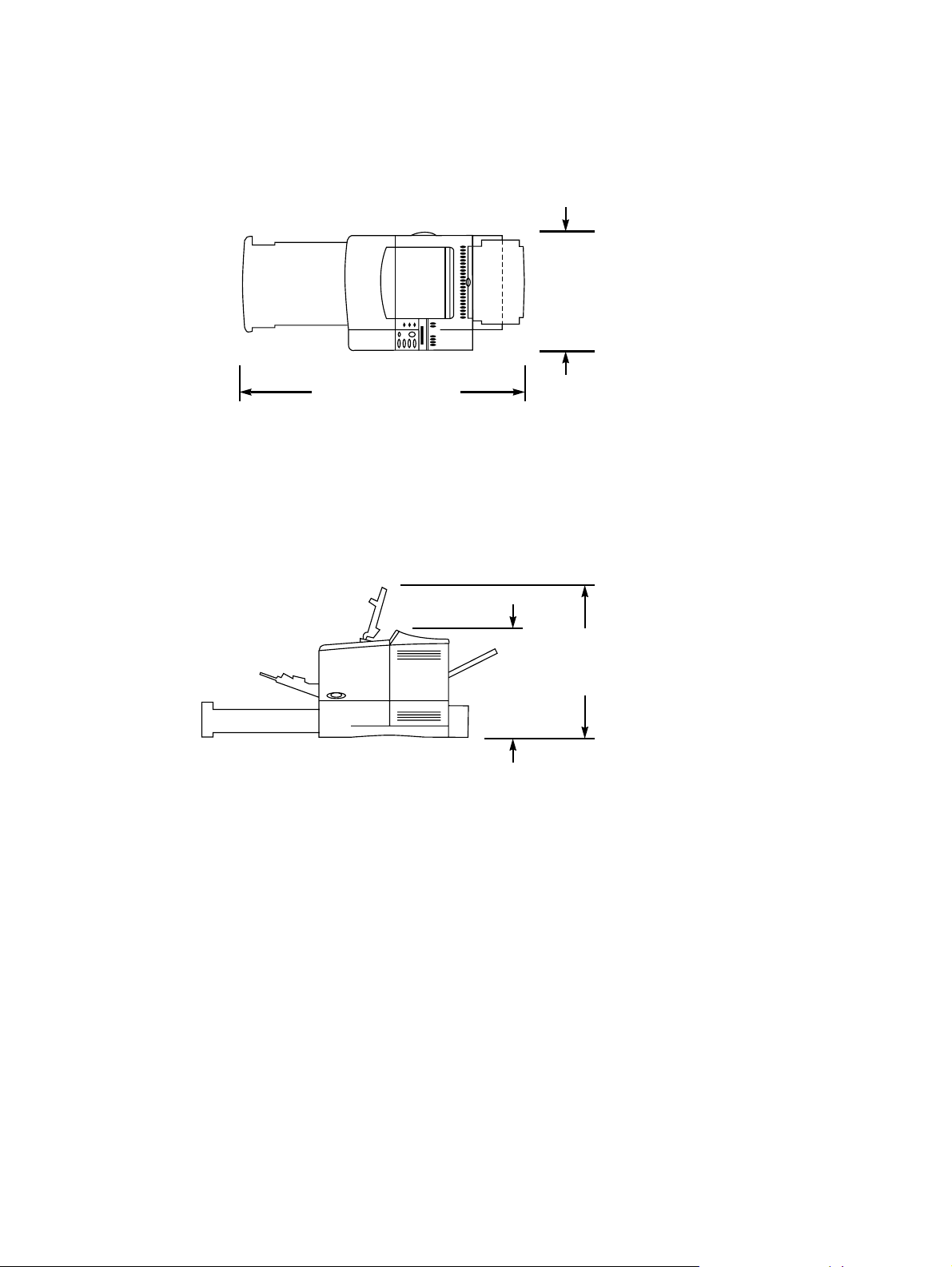
Installation requirements
Install the printer with enough space around it to open trays and bins, install toner, and perform
maintenance. If the duple xer is installed, the printer needs 101 mm (4 inches) of ventilation space on
the left side (fan side) and rear of the printer.
390 mm
(15.4 inches)
1043 mm (41.1 inches)
Figure 2. Top view, HP LaserJet 4100/4100N/4100TN/4100DTN printer with trays and rear output bin
open
Figure 3. Side view, HP LaserJet 4100/4100N printer
345 mm
top cover closed
(13.6 inches) with
475 mm
top cover open
(18.7 inches) with
22 Printer description EN
Page 25

465 mm
Figure 4. Side view, HP LaserJet 4100TN/4100DTN printer
Printer weight (without toner cartridge)
HP LaserJet 4100/4100N printers: 18 kg (39 lb)
!
HP LaserJet 4100TN printer: 25 kg (55 lb)
!
HP LaserJet 4100DTN printer: 28 kg (62 lb)
!
595 mm
top cover open
cover closed
(18.3 inches) with top
(23.4 inches) with
EN Chapter 1 Printer description 23
Page 26

Environmental requirements
Table 4. Printer and toner cartridge environmental conditions
Item Operating Storage
Temperature 10
° to 32°
C (50 to 91° F) Toner cartridge:
0
to 35°C (32 to 95° F)
°
Printer:
-20 to 60°C (-4
Relative humidity 20 to 80 percent relative
10 to 95 percent RH
humidity (RH) (with no
condensation)
Table 5. Operating sound power or pressure (Per ISO 9296)
Sound power level L
Operating position L
Bystander position L
= 6.6 Bels (A) printing, L
WAd
= 58 dB (A) printing, L
pAm
= 52 dB (A) printing, L
pAm
= 4.1 Bels (A) idle
WAd
= 32 dB (A) idle
pAm
= 26 dB (A) idle
pAm
Note Testing per International Standards Organization (ISO) 9296/7779
to 140° F)
°
24 Printer description EN
Page 27

Print media specifications
The following tables show print media specifications for the HP LaserJet 4100 series printer.
Table 6. Print media specifications, tray 1
Supported
media Dimensions
Minimum size
(custom
Maximum size
(custom
3
)
3
)
76 by 127 mm
(3 by 5 inches)
216 by 356 mm
(8.5 by 14 inches)
Transparencies Same as minimum
and maximum paper
sizes listed above
1
Weight Capacity
60 to 199 g/m
2
100 sheets of 75 g/m
(16 to 53 lb)
Thickness:
2
2
(20 lb) paper
50 transparencies
0.10 to 0.11 mm
(0.0039 to
0.0043 inch)
Labels Thickness:
50 labels
0.13 to 0.18 mm
(0.005 to 0.007
inch)
Envelopes 75 to 105 g/m
2
10 envelopes
(20 to 28 lb)
1.
The printer supports a wide range of print media sizes. Check the printer software for
supporte d sizes. To prin t cu sto m -size media, see th e user guide.
2.
Capacity can vary depending on media weight and thickness, and environmental conditions.
3.
Custom media must be fed short-edge first (portrait).
EN Chapter 1 Printer description 25
Page 28
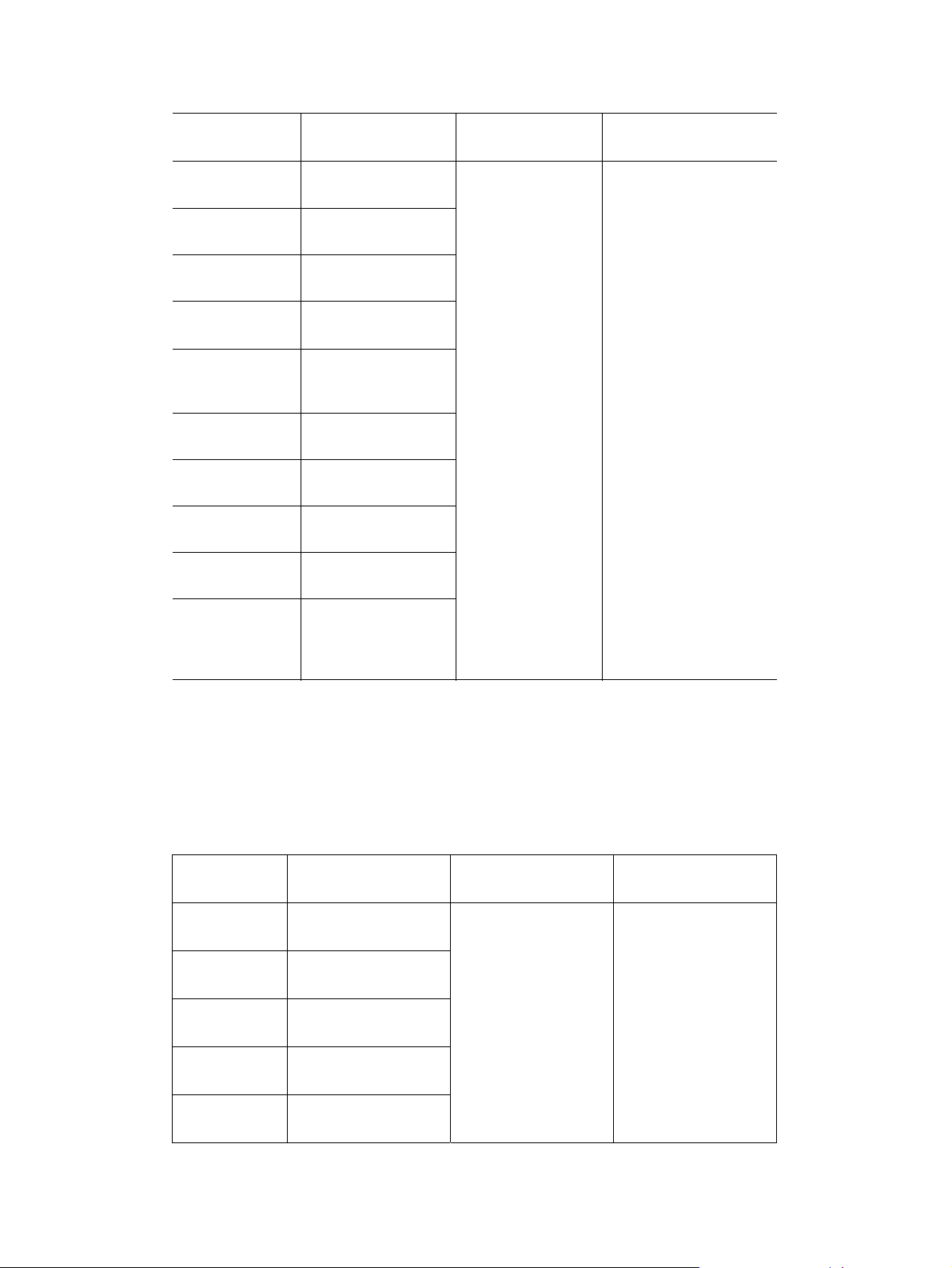
Table 7. Print media specifications, trays 2, 3, and 4
Supported
media Dimensions
1
Letter 216 by 279 mm
(8.5 by 11 inches)
A4 210 by 297 mm
(8.3 by 11.7 inches)
Executive 191 by 267 mm
(7.3 by 10.5 inches)
Executive (JIS)
(custom
3
)
16K (custom
216 by 330 mm
(8.5 by 13 inches)
3
) 197 by 273 mm
(7.75 by 10.75
inches)
Legal 216 by 356 mm
(8.5 by 14 inches)
B5 (ISO)
(custom
B5 (JIS)
A5
3
)
176 by 250 mm
(6.9 by 9.9 inches)
182 by 257 mm
(7.2 by 10 inches)
148 by 210 mm
(5.8 by 8.2 inches)
Weight Capaci ty
60 to 105 g/m
2
(16 to 28 lb)
500 sheets of 75 g/m
(20 lb) paper or
50 transparencies
2
2
148 by 210 mm
Custom
3
to 216 by 356 mm
(5.8 by 8.2 inches to
8.5 by 14 inches)
1.
The printer supports a wide range of print media sizes. Check the printer software for
supporte d sizes. To prin t cu sto m -size media, see th e user guide.
2.
Capacity can vary depending on media weight and thickness, and environmental conditions.
3.
Custom media must be fed short-edge first (portrait).
Table 8. Print media specifications, optional envelope feeder
Supported
envelope Dimensions Weight Capacity
Monarch
(#7 3/4)
Commercial 10
(#10)
DL ISO 110 by 220 mm
98.4 by 190.5 mm
(3.88 by 7.50 inches)
104.9 by 241.3 mm
(4.13 by 9.5 inches)
(4.33 by 8.66 inches)
75 to 105 g/m2
(20 to 28 lb)
1
75 envelopes
C5 ISO 162 by 229 mm
(6.38 by 9.02 inches)
B5 ISO 176 by 250 mm
(6.93 by 9.84 inches)
1.
Capacity can vary depending on media weight and thickness, and environmental conditions.
26 Printer description EN
Page 29

Table 9. Print media specifications, optional duplexer
Supported
media Dimensions Weight
Letter 216 by 279 mm
(8.5 by 11 inches)
A4 210 by 297 mm
(8.3 by 11.7 inches)
Executive 184 by 267 mm
(7.3 by 10.5 inches)
Legal 216 by 356 mm
(8.5 by 14 inches)
B5 (JIS) 182 by 257 mm
(7.2 by 10 inches)
60 to 105 g/m2
(16 to 28 lb)
EN Chapter 1 Printer description 27
Page 30

Supported types of print media
The printer supports the following types of print media:
plain
!
letterhead
!
prepunched
!
bond
!
color
!
rough
!
preprinted
!
transparency (see page 32)
!
labels (see page 31)
!
recycled
!
card stock
!
Note Transparencies and labels must be specified for use in laser printers.
28 Printer description EN
Page 31

Types of print media to avoid
The following characteristics can affect the performance of th e HP L aserJe t print er un less t he pap er
or other print media used is specifically designed to work with the HP LaserJet printer.
Print media that is very rough, highly textu red, or heavily embossed.
!
Print media with multipart forms.
!
Print media that offsets materials or discolors.
!
Print media that is damaged, curled, wrinkled, or irregularly shaped.
!
Paper that is extremely shiny or glossy.
!
Paper, labels, envelopes, or transparencies that produce undesirable emissions or melt when
!
exposed to a fusing temperature between 175° to 230° C (347° to 446° F) for 0.1 second.
Media coatings, dyes, or inks that produce undesirable emissions or melt when exposed to a
!
fusing temperature between 175° to 230° C (347° to 446° F) for 0.1 second.
Envelopes that have an open flap with the adhesive exposed so that closing the flap seals the
!
envelope.
Envelopes with clasps, snaps, tie strings, windows, or synt hetic materials. These materials can
!
severely damage the printer.
Envelopes that are not square, straight, or constructed correctly (see "Envelope constructi on" on
!
page 33).
Envelopes with a basis weight less than 60 g/m2 (16 lb) or greater than 105 g/m2 (28 lb).
!
Envelopes with baggy construction or folds that are not sharply creased.
!
Note Some media types might not w ork in the printer because of diff erences in man uf acturer specifications
or environmental conditions.
EN Chapter 1 Printer description 29
Page 32

Weight equivalence table
The following table shows equivalent weights for different grades of paper. A boldface type value
indicates a commonly available standard weight for that grade. Shaded boxes indicate a commonly
available standard weight for that grade.
Note Text and book grades marked with an asterisk (*) actually calculate to 51, 61, 71, and 81 but are
rounded to standard book or text weights of 50, 60, 70, and 80.
Table 10. Weight equivalence table
Bond
weight
(17 by 22
inches)
16# 41# 22# 27# 33# 37# 60 g/m
17# 43# 24# 29# 35# 39# 64 g/m
20# 50# * 28# 34# 42# 46# 75 g/m
21# 54# 30# 36# 44# 49# 80 g/m
24# 60# * 33# 41# 50# 55# 90 g/m
27# 68# 37# 45# 55# 61# 100 g/m
28# 70# * 39# 49# 58# 65# 105 g/m
29# 74# 41# 50# 61# 68# 110 g/m
32# 80# * 44# 55# 67# 74# 120 g/m
36# 90# 50# 62# 75# 83# 135 g/m
39# 100# 55# 67# 82# 91# 148 g/m
40# 101# 55# 68# 83# 92# 150 g/m
43# 110# 60# 74# 90# 100# 163 g/m
45# 115# 63# 77# 94# 104# 170 g/m
47# 119# 65# 80# 97# 108# 176 g/m
51# 128# 70# 86# 105# 117# 190 g/m
53# 134# 74# 90# 110# 122# 199 g/m
54# 137# 75# 93# 113# 125# 203 g/m
58# 146#
65# 165# 90# 111# 135# 150# 244 g/m
66# 169# 92# 114# 138# 154# 250 g/m
67# 171# 94# 115# 140# 155# 253 g/m
70# 178# 98# 120# 146# 162# 264 g/m
72# 183# 100# 123# 150# 166# 271 g/m
Book/text
weight
(25 by 38
inches)
Cover
weight
(20 by 26
inches)
80# 98# 120# 133# 216 g/m
Bristol
weight
(22.5 by 28.5
inches)
Index
weight
(25.5 by 30.5
inches)
Tag
weight
(24 by 36
inches)
Metric
weight
2
2
2
2
2
2
2
2
2
2
2
2
2
2
2
2
2
2
2
2
2
2
2
2
30 Printer description EN
Page 33

Adhesive labels
When printing on labels, use of tray 1 is recommended. Labels are multiple-layer media typically
consisting of a face sheet (the printable surface), pressure-sensitive adhesive, and a liner (a carrier
sheet coated with a release agent). Labels used in the HP LaserJet printer must be specifically
designed for laser printers . If labels othe r than those comp atib le with laser printers are used, there is
a significant risk of labels peeling or of adh esiv e conta mination that can severely damage the printer .
All materials in laser label stock must be compatib le with the hea t and pressure of the fu sing process .
The table below summarizes the adhesive label specifications that provide the best performance.
Table 11. Adhesive labels specifications
Property Specifications
Adhesive Must not be on any external surfaces of the label before,
during, or after printing. Label construction, adhesive
release strength, and die-cutting must not allow labels to
peel off during printing.
Caliper (thickness) Must not exceed 0.23 mm (9.0 mils).
Fusing compatibility All inks, adhesives, and other materials used in the label
construction must be compatible with the heat and
pressure of the fusing process. Materials must not scorch,
melt, ignite, offset materials, or release unde sirable
emissions when heated to a temperature between
175° to 230° C (347° to 446° F) for 0.1 second.
Packaging Adhesive labels should be packaged in moisture-proof
wrap to preserve properties.
Shelf life One year maximum, stored at 23° C (73° F) and 50
percent RH.
EN Chapter 1 Printer description 31
Page 34

Overhead transparencies
When printing transparencies, use of tray 1 is recommended. Overhead transparency film must be
designed specifically for use with laser printers. Photocopy tr ansparency film might not be
compatible with laser printers because of higher temperature and stiffness requirements.
Overhead transparency film is very smooth and must have a topcoat to provide the proper electrical
and toner adhesion properties. A transparency that is made of poor materials or that is too thin can
easily melt in the fuser and damage the printer.
Overhead transparency materials must be compatible with the heat and pressure of the fusing
process.
The table below summarizes the overhead transparency specifications that provide the best
performance.
Table 12. Overhead transparencies specifications
Property Specifications
Caliper (thickness) 0.10 mm to 0.11 mm (4.0 mils to 4.4 mils).
Electrical surface
resistivity
Fusing compatibility Overhead transparency materials must be compatible with
2.0 to 15 by 10
the heat and pressure of the fusing process. Materials
must not discolor, melt, offset materials, or release
undesirable emissions when heated to a temperature
between 175° to 230° C (347° to 446° F) for 0.1 second.
10
ohms/square.
32 Printer description EN
Page 35

Envelopes
Envelope construction
Envelopes can only be printed from tray 1 or from the optional envelo pe feeder. Because of their
construction, some envelopes will not feed through the printer dependably. Observe the following
guidelines when purchasing and using env elop es:
Make sure the envelope’s leading edge, which enters the printer first, is straight, with a sharp,
!
well-creased fold that has no more than two thicknesses of paper. Envelopes that exceed
105 g/m
Avoid using flimsy envelopes with thick or curved leading edges; they will not feed reliably.
!
Envelopes should lie flat and should not be wrinkled, nicked, or otherwise da maged.
!
Avoid envelopes with baggy construction; they might wrinkle while going through the printer’s
!
fuser assembly.
Make sure that the adhesive labels used on envelopes will not scorch, melt, offset, or release
!
undesirable emissions when heated to a temperature between 175° to 230° C (347° to 446° F)
for 0.1 second.
Av oid usin g en v elopes with encapsulat ed adhesiv es th at rely on pressu re ra ther than moist ening
!
to seal.
Do not use envelopes with clasps, snaps, tie strings, transparent windows, holes, perforations, or
!
cutouts.
Do not use envelopes that have any ad h esive surfaces exposed to the printer.
!
Woven or smooth finishes are recommended to ensure good toner adhesion on envelopes.
!
2
(28 lb) basis weight can cause jamming.
Many envelopes will feed through the HP LaserJet printer without problems. However, some
envelope constructions (as shown in the figure below) will not feed reliably. Problems can occur
when the envelopes are folded more tightly than no rmal, causing a thick leading edg e near a corner .
Folding inconsistencies at the manufacturer can cause some envelopes to feed well and others to
jam.
Good construction Bad construction
EN Chapter 1 Printer description 33
Page 36

Envelope specifications
The table below summarizes the envelope specifications that provide the best performance.
Table 13. Envelope specificati ons
Property Specifications
Basis weight 64 g/m
See the user guide for specific printer and input limits.
Caliper (thickness) 0.09 mm to 0.14 mm (3.6 mil to 5.5 mil) typical single-layer
thickness.
Surface roughness 100 to 200 Sheffield.
Fusing compatibility All inks, adhesives, and other materials used in the
envelope const ruction must be compatible with the heat
and pressure of the fusing process. Materials must not
scorch, melt, ignite, offset materials, or release
undesirable emissions when heated to a temperature
between 175° to 230° C (347° to 446° F) for 0.1 second.
2
to 105 g/m2 (17 lb to 28 lb) typical.
Dimensional accuracy
and construction quality
Envelopes m ust be f olded within ±1.0 mm (±0.04 inch)
!
of nominal size with no more than two thickness of
paper anywhere along the leading edge.
All folds must be sharply creased and construction
!
must be tight (not baggy) to avoid wrinkling.
Envelopes must not be stuck together from excess
!
seam adhesive (blocking).
The flap must be flat within 1.5 mm (0 .059 in ) o ver the
!
width where adhesive is applied.
Curl Envelopes must lie flat, with no more than 6 mm (0.25
inch) curl across the entire surface.
Adhesive flap curl Envelope flap should be flat, with 1.5 mm (0.059 inch)
over the width where adhesive is applied.
Moisture content 4 percent to 6 percent by weight.
Grain Different envelope constructions might require different
grain orientations f or best perf ormance, which is le ft to the
discretion of the manufacturer.
Packaging Envelopes should be contained in a protective box to
prevent edge damage and maintain flatness.
34 Printer description EN
Page 37

Card stock and heavy paper
Many types of card stoc k an d pa pe r can be p rinted from t r ay 1, including index cards and postcards.
For optimum printer performance, do not use paper heavier than 199 g/m
105 g/m
2
(28 lb) in other trays. Paper that is too heavy might cause misfeeds, stacking problems,
jams, poor toner fusing, poor print quality, or excessive mechanical wear.
Note Before loading card stoc k, make sure it is regular in shape and not damaged or wrinkled. Also, make
sure the cards are not stuck together.
The table below summarizes the paper specifications that provide the best performance.
Table 14. Paper specifications
Property Specifications
Basis weight 64 g/m
2
to 105 g/m2 (17 lb to 28 lb) typical.
See the user guide for specific printer and input limits.
Caliper (thickness) 0.09 mm to 0.17 mm (3.5 mil to 6.5 mil) typical.
See the user guide for specific printer and input limits.
Minimum stiffness 1.2 minimum (Taber) machine direction;
0.8 minimum (Taber) cross direction.
Grain Portrait feeding: short or long grain up to 36 lb.
Landscape feeding: long grain.
Electrical surface
9
10
to 1013 ohms/square.
resistivity
9
Electrical volume
to 1014 ohms - cm.
10
resistivity
Surface roughness 100 to 190 Sheffield optimal;
30 to 350 Sheffield extended (fusing or feeding
performance can be degraded at outer ranges).
Fusing compatibility Must not scorch, melt, ignite, offset materials, or release
undesirable emissions when heated to a temperature
between 175° to 230° C (347° to 446° F) for 0.1 second.
2
(53 lb) in tray 1 or
Furnish (composition) One hundred percent chemical pulp and/or cotton con tent;
recycled paper with up to 5 percent groundwood can be
used.
Dimensional accuracy Cut sheet within ±0.80 mm (±0.03 inch) of nominal.
Cut edge quality Cuts must be smooth and clean with no fray or edge roll.
Curl Must lie flat within 5 mm (0.2 inch).
Moisture content 4 percent to 6 percent by weight.
Packaging Card stock and heavy paper should be packaged in a
moisture-proof ream wrap.
Wax pick 12 minimum (Dennison).
EN Chapter 1 Printer description 35
Page 38

Safety information
Toner safety
Handling and storage
WARNING! Keep toner cartridges and toner particles away from excessive heat, sparks, and open flames.
If toner is spilled, avoid breathing in toner particles. Inhalation of toner particles can cause
respiratory tract irritation. Vacuum or sweep the material into a bag or other sealed contai ner. If a
vacuum is used, the motor must be rated as dust-tight.
Dispose of waste toner in accordance with local requirements. Do not discharge toner particles in
drains.
First aid measures
Ingestion. If toner is ingested, drink sever al glasses of w ater. Get medical attention if discomfort
!
persists.
Inhalation. If toner particles are inhaled, move to fresh air immediatel y. If symptoms occur (such
!
as coughing, dizziness, or difficulty breathing), consult a physician.
Eye contact. If toner comes in contact with the ey es , immediate ly flush with plenty of w ater for at
!
least 15 minutes. If irritation persists, consult a physician.
Skin contact. If toner spills on skin, remove as much toner as possible with a dry tissue, and
!
then wash with cold water.
Clothing contact
Note Toner can stain clothing. Hot water or heat (from a clothes dryer) can cause toner to melt and
permanently fuse into clothing.
Clothing is best cleaned by removing as much toner as possible with a dry tissue, and then washing
with cold water. Air-dry clothing.
Additional information
The Toner Cartridge/Drum Material Safety Data Sheet (MSDS) can be obtained by contacting HP at
the following website:
http://www.ljsupplies.com
36 Printer description EN
Page 39

Laser safety
Do not open the laser scanner assembly. Avoid direct exposure to the laser beams.
WARNING! Using controls, making adjustments , b ypassing saf ety s witches , or perf orming procedures oth er than
those specified in this service manual can result in exposure to hazardous radiation.
Regulatory information
For regulatory information and requirements, please see the user guide .
EN Chapter 1 Printer description 37
Page 40

38 Printer description EN
Page 41

2
Service approach
Chapter contents
Service approach . . . . . . . . . . . . . . . . . . . . . . . . . . . . . . . . . . . . . . . . . . . . . . . . . . . . . . . . . . . 40
Parts and supplies. . . . . . . . . . . . . . . . . . . . . . . . . . . . . . . . . . . . . . . . . . . . . . . . . . . . . . . . . . . 40
Ordering information . . . . . . . . . . . . . . . . . . . . . . . . . . . . . . . . . . . . . . . . . . . . . . . . . . . . 40
Printer documentation . . . . . . . . . . . . . . . . . . . . . . . . . . . . . . . . . . . . . . . . . . . . . . . . . . . 41
HP direct ordering for genuine HP parts . . . . . . . . . . . . . . . . . . . . . . . . . . . . . . . . . . . . . 42
Exchange program . . . . . . . . . . . . . . . . . . . . . . . . . . . . . . . . . . . . . . . . . . . . . . . . . . . . . 42
Consumables. . . . . . . . . . . . . . . . . . . . . . . . . . . . . . . . . . . . . . . . . . . . . . . . . . . . . . . . . . 42
World Wide Web . . . . . . . . . . . . . . . . . . . . . . . . . . . . . . . . . . . . . . . . . . . . . . . . . . . . . . . 42
HP service parts information compact disc . . . . . . . . . . . . . . . . . . . . . . . . . . . . . . . . . . . 42
HP support assistant compact disc . . . . . . . . . . . . . . . . . . . . . . . . . . . . . . . . . . . . . . . . . 43
Toner cartridge information . . . . . . . . . . . . . . . . . . . . . . . . . . . . . . . . . . . . . . . . . . . . . . . 44
Warranty statement. . . . . . . . . . . . . . . . . . . . . . . . . . . . . . . . . . . . . . . . . . . . . . . . . . . . . . . . . . 45
Printer warranty . . . . . . . . . . . . . . . . . . . . . . . . . . . . . . . . . . . . . . . . . . . . . . . . . . . . . . . . 45
Limited warranty for toner cartridge life . . . . . . . . . . . . . . . . . . . . . . . . . . . . . . . . . . . . . . 45
EN Chapter 2 Service approach 39
Page 42

Service approach
Repair of the printer normally begins with use of the printer’s internal diagnostics in conjunction with
the troubleshooting procedures in chapter 7. When a faulty part is located, repair is generally
accomplished by assembly-level replacement of field-replaceable units (FRUs). Some mechanical
assemblies might be repaired at the subassembly level. Hewlett-Packard does not support
replacement of components on printed circuit boards.
Parts and supplies
Ordering information
Chapter 8 of this manual contains FRU and accessory part numbers. Replacement parts can be
ordered from the HP Customer Services and Support Organization.
Use only accessories specifically designed for this printer. Order accessories from an authorized
service or support provider. (See page 42.)
40 Service approach EN
Page 43

Printer documentation
The table below lists part numbers to use when ordering documentation. For information about
ordering, see page 42.
Note Some of the materials listed in table 15 are also available online at http://www.hp.com.
Table 15. Printer documentation
Item Description or use Part number
HP LaserJet Printer Family
Print Media Guide
PCL 5/PJL Technical
Reference Documentation
Package
HP LaserJet Basics
CD-ROM
User Getting Started Guide,
HP LaserJet 4100 Series
Printers
HP LaserJet 4100 Series
Printers User Documentation
CD-ROM
HP LaserJet 4100 Series
Printers Software Technical
Reference
A guide to using paper and
other print media with
HP LaserJet printers
A guide to using printer
commands with HP LaserJet
printers
A guide to using HP LaserJet
printer hardware
An additional copy of the user
getting started guide
An additional copy of the user
documentation CD-ROM
A guide to the printer software C8049-90921
5963-7863
(English only)
5021-0330
(English only)
H8789A
(English only);
online at: http://
software.hp.com
C8049-90903
(English only)
C8049-60104
(English only)
(English only)
Service and Support CDROM for the
HP LaserJet 4100 Series
Printers
HP LaserJet 4100 Series
Printers Service Manual
HP LaserJet 4100 Series
Printers Training Kit
EN Chapter 2 Service approach 41
An interactive training CDROM for printer service
representatives and custom er
care specialists
A service manual for the 4100
printer series.
Includes service manual and
service and suppo rt CD-ROM
C8049-60116
(English only)
C8049-90920
(English only)
C8049-67901
(English only)
Page 44

HP direct ordering for genuine HP parts
Customer Services and Support Organization (CSSO):
(1) (800) 227-8164 (U.S. only)
!
(49 7031) 142253 (Europe only)
!
See chapter 8 for additional information.
!
Exchange program
HP offers remanufactured assemblies for som e pa rts. These are identified in chap te r 8 and can be
ordered through CSSO.
Consumables
Paper and ton er cartridges can be ordered directly from Hewlett-Packard. See chapter 8 for o rdering
information.
World Wide Web
Printer drivers, updated HP printer software, and product and support information can be obtained
from the following URL:
in the U.S., http://www.hp.com/suppor t/ lj41 00
Printer drivers can be obtained from the following sites:
in China, ftp://www.hp.com.cn/support/lj4100
in Japan, ftp://www.jpn.hp.com/supp ort/lj4100
in Korea, http://www.hp.co.kr/support/lj4100
in Taiwan, http://www.hp.com.tw/sup p ort/lj4100
or the local driver website, http://www.dds.com.tw
HP service parts information compact disc
This powerful, CD-ROM-based parts information tool is designed to give users fast, easy access to
parts information and recommended stocking lists for a wide range of HP products. To subscribe to
this quarterly service in the U.S. or Canada, call (1) (800) 336-5987. In Asia Pacific , call (65) 740-
4484. Parts identification and pricing information can also be fou nd on the World Wide Web at: http:/
/www.hp.com/go/partsinfo
42 Service approach EN
Page 45

HP support assistant compact disc
This support tool offers a comprehensive on line information system designed to provide technical
and product information about He wlett-Packard products. To subscribe to this quarterly service in the
U.S. or Canada, call (1) (800) 457-1762. In Hong Kong, Indonesia, Malaysia, or Singapore, call
Mentor Media at (65) 740-4477.
Customer care reseller sales and service support center
The Customer Care Reseller Sales and Service Support Center is available to assist resellers and
service technicians. To reach this support center, call (1) (800) 544-9976.
HP authorized resellers and support
To locate authorized HP resellers and support, call
(1) (800) 243-9816 in the U.S. or (1) (800) 387-3867 in Canada.
HP service agreements
Call (1) (800) 743-8305 in the U.S. or (1) (800) 268-1221 in Canada.
Other areas
Outside of North America and Europe, contact the local HP sales office for assistance in obtaining
technical support for resellers and service technicians.
EN Chapter 2 Service approach 43
Page 46

Toner cartridge information
The toner cartridge is designed to simplify replacement of the major “consumable” parts. The toner
cartridge contains the printing mechanism and a supply of toner.
At five percent page coverage, a toner cartridge will print approximately 6,000 or 10,000 pages,
depending on the toner cartridge model installed. A toner cartridge might print fewer pages if
routinely printing with dense ink coverag e, or more pages when routin ely printing pages with less ink
cover age, such as short memos. If EconoMode or small media is always used, however, the toner
supply could outlast the mechanical parts in the toner cartridge.
Note For best results , alwa ys use a toner cartridge before the expirat ion date stamped on the toner cartridge
box.
Refilled toner cartridges
While Hewlett-Packard does not prohibit the use of refilled toner cartridges during the warranty
period or while the printer is under a maintenance contract, it is not recommended for the following
reasons:
Repairs resulting from the use of refilled toner cartridges are not covered under Hewlett-P ac kard
!
warranty or maintenance contracts.
Hewlett-Packard has no control or process to ensure that a refilled toner cartridge functions at
!
the high level of reliability of a new HP LaserJet toner cartridge. Hewlett-Packard also cannot
predict the long-term reliability effect on the printer from using different toner formulations found
in refilled cartridges.
The print quality of HP LaserJet toner cartridges influences the customer’s perception of the
!
printer. Hewlett-Packard has no control over the actual print quality of a refilled toner cartridge.
Recycling toner cartridges
To reduce waste, Hewlett-Packard offers a r ecycling program for used toner cartridges. Cartridge
components that do not wear out are recycled . Plastics and other materials are recycled.
Hewlett-Packard pays the shipping costs from the user to the recycling plant. For each cartridge
returned, Hewlett-Packard donates one U.S . dollar to be shared by the Nature Conservancy and the
National Wildlife Federation. To join this recycling effort, follow the instructions inside the toner
cartridge box.
44 Service approach EN
Page 47

Warranty statement
The warranty for this product gives the customer specific legal rights. There might also be other
rights that vary from area to area.
Printer warranty
Hewlett-Packard warrants the HP LaserJet 4100 series printer for one year. For detailed information
about the printer warranty, see the limited warranty statement in the user guide.
Limited warranty for toner cartridge life
Note The warranty belo w applies to the toner cartridge that came with this printer. This w arranty supersedes
all previous warranties (7/19/96).
The HP toner cartridge is warranted to be free from defects in materials and workmanship for the life
of the cartridge until the HP toner is depleted. The HP toner is depleted when the printer indicates a
toner-low message. Hewlett-Packard will, at its option, either replace products that prove to be
defective or refund the purchase price.
The warranty does not cover toner cartridges that have been refilled, or are emptied, abused,
misused, or tampered with in any way. This limited warranty gives the customer specific legal rights.
The customer might have other rights which vary from state to state, province to province, and
country to country.
To the extent allow ed by applicable law, in no event shall Hewlett-Packard Company be liable for any
incidental, consequential, special, indirect, punitive, or exemplary damages or lost profits from any
break of this warranty or otherwise.
EN Chapter 2 Service approach 45
Page 48

46 Service approach EN
Page 49

3
Printer operation
Chapter contents
Using the control panel . . . . . . . . . . . . . . . . . . . . . . . . . . . . . . . . . . . . . . . . . . . . . . . . . . . . . . . 49
Control panel layout. . . . . . . . . . . . . . . . . . . . . . . . . . . . . . . . . . . . . . . . . . . . . . . . . . . . . 49
Control panel lights . . . . . . . . . . . . . . . . . . . . . . . . . . . . . . . . . . . . . . . . . . . . . . . . . . . . . 49
Control panel keys. . . . . . . . . . . . . . . . . . . . . . . . . . . . . . . . . . . . . . . . . . . . . . . . . . . . . . 50
Settings and defaults. . . . . . . . . . . . . . . . . . . . . . . . . . . . . . . . . . . . . . . . . . . . . . . . . . . . 51
Control panel menus . . . . . . . . . . . . . . . . . . . . . . . . . . . . . . . . . . . . . . . . . . . . . . . . . . . . . . . . . 52
Quick copy jobs menu . . . . . . . . . . . . . . . . . . . . . . . . . . . . . . . . . . . . . . . . . . . . . . . . . . . 53
Private/stored jobs menu. . . . . . . . . . . . . . . . . . . . . . . . . . . . . . . . . . . . . . . . . . . . . . . . . 54
Information menu. . . . . . . . . . . . . . . . . . . . . . . . . . . . . . . . . . . . . . . . . . . . . . . . . . . . . . . 55
Paper-handling menu . . . . . . . . . . . . . . . . . . . . . . . . . . . . . . . . . . . . . . . . . . . . . . . . . . . 57
Printing menu . . . . . . . . . . . . . . . . . . . . . . . . . . . . . . . . . . . . . . . . . . . . . . . . . . . . . . . . . 60
Print quality menu . . . . . . . . . . . . . . . . . . . . . . . . . . . . . . . . . . . . . . . . . . . . . . . . . . . . . . 63
Configuration menu . . . . . . . . . . . . . . . . . . . . . . . . . . . . . . . . . . . . . . . . . . . . . . . . . . . . . 66
I/O menu . . . . . . . . . . . . . . . . . . . . . . . . . . . . . . . . . . . . . . . . . . . . . . . . . . . . . . . . . . . . . 69
EIO menu (networked printers) . . . . . . . . . . . . . . . . . . . . . . . . . . . . . . . . . . . . . . . . . . . . 70
Resets menu . . . . . . . . . . . . . . . . . . . . . . . . . . . . . . . . . . . . . . . . . . . . . . . . . . . . . . . . . . 73
Service mode . . . . . . . . . . . . . . . . . . . . . . . . . . . . . . . . . . . . . . . . . . . . . . . . . . . . . . . . . . . . . . 74
Page count . . . . . . . . . . . . . . . . . . . . . . . . . . . . . . . . . . . . . . . . . . . . . . . . . . . . . . . . . . . 77
Maintenance count . . . . . . . . . . . . . . . . . . . . . . . . . . . . . . . . . . . . . . . . . . . . . . . . . . . . . 77
Maintenance interval . . . . . . . . . . . . . . . . . . . . . . . . . . . . . . . . . . . . . . . . . . . . . . . . . . . . 77
Serial number . . . . . . . . . . . . . . . . . . . . . . . . . . . . . . . . . . . . . . . . . . . . . . . . . . . . . . . . . 77
Cold reset paper . . . . . . . . . . . . . . . . . . . . . . . . . . . . . . . . . . . . . . . . . . . . . . . . . . . . . . . 77
Diagnostics . . . . . . . . . . . . . . . . . . . . . . . . . . . . . . . . . . . . . . . . . . . . . . . . . . . . . . . . . . . 77
Clear event log . . . . . . . . . . . . . . . . . . . . . . . . . . . . . . . . . . . . . . . . . . . . . . . . . . . . . . . . 78
Top margin . . . . . . . . . . . . . . . . . . . . . . . . . . . . . . . . . . . . . . . . . . . . . . . . . . . . . . . . . . . 78
Tray 1 left margin. . . . . . . . . . . . . . . . . . . . . . . . . . . . . . . . . . . . . . . . . . . . . . . . . . . . . . . 78
Trays 2 and 3 left margin. . . . . . . . . . . . . . . . . . . . . . . . . . . . . . . . . . . . . . . . . . . . . . . . . 78
Testing the printer . . . . . . . . . . . . . . . . . . . . . . . . . . . . . . . . . . . . . . . . . . . . . . . . . . . . . . . . . . . 78
Engine test. . . . . . . . . . . . . . . . . . . . . . . . . . . . . . . . . . . . . . . . . . . . . . . . . . . . . . . . . . . . 78
Resetting the printer . . . . . . . . . . . . . . . . . . . . . . . . . . . . . . . . . . . . . . . . . . . . . . . . . . . . . . . . . 79
Cold reset . . . . . . . . . . . . . . . . . . . . . . . . . . . . . . . . . . . . . . . . . . . . . . . . . . . . . . . . . . . . 79
Clearing NVRAM . . . . . . . . . . . . . . . . . . . . . . . . . . . . . . . . . . . . . . . . . . . . . . . . . . . . . . . 79
Initialization of NVRAM . . . . . . . . . . . . . . . . . . . . . . . . . . . . . . . . . . . . . . . . . . . . . . . . . . 79
EN Chapter 3 Printer operation 47
Page 50

Initialization of the hard disk . . . . . . . . . . . . . . . . . . . . . . . . . . . . . . . . . . . . . . . . . . . . . . .80
System configuration . . . . . . . . . . . . . . . . . . . . . . . . . . . . . . . . . . . . . . . . . . . . . . . . . . . . . . . . .80
MS-DOS system configuration . . . . . . . . . . . . . . . . . . . . . . . . . . . . . . . . . . . . . . . . . . . . .80
Parallel DOS commands. . . . . . . . . . . . . . . . . . . . . . . . . . . . . . . . . . . . . . . . . . . . . . . . . .80
48 Printer operation EN
Page 51

Using the control panel
Control panel layout
The printer control panel consists of a two-line display and lights and keys as shown below:
2-line
display
Ready
Data
Attention
Figure 5. Control panel layout
Control panel lights
Table 16. Control panel lights
READY
Go
Cancel
Job
Menu
Item
– Value +
Select
Light Indication
Ready The printer is ready to print.
Data The printer is processing informa tio n.
Attention Action is required. See the control panel display .
EN Chapter 3 Printer operation 49
Page 52

Control panel keys
Table 17. Control panel keys
Key Function
G
O
C
ANCEL JOB
M
ENU
Places the printer either online or offline.
!
Prints any data in the printer’s buffer.
!
Allows the printer to resume printing after being offline.
!
Clears most printer messages and places the printer
online.
Allows the printer to continue printing with an error
!
message such as
UNEXPECTED PAPER SIZE
Confirms a manual feed request if tray 1 is loaded and
!
TRAY 1 MODE=CASSETTE
TRAY X LOAD [TYPE] [SIZE]
.
has been set from the paper-
or
handling menu on the printer control panel.
Overrides a manual feed request from tray 1 by
!
selecting paper from the next available tray.
Exits the control panel menus. (To save a selected
!
control panel setting, first press S
ELECT
.)
Cancels the print job that the printer is processing. The time
and pages it takes to cancel depends on the size of the
print job and the number of pages in the buffer. (Press it
only once.)
Cycles through the control panel menus. Press the right
end of the button to move forward or the left end of the
button to move backward.
I
TEM
– V
S
ELECT
[?]
Cycles through the selected menu’s items. Press the right
end of the button to move forward or the left end of the
button to move backward.
+ Cycles through the selected menu item’s values. Press + to
ALUE
move forward or – to move backward.
Saves the selected value for that item. An asterisk (*)
!
appears next to the selection to indicate that it is the
new default. Default settings remain when the printer is
switched off or reset.
Prints any information pages shown in the control
!
panel.
Provides instructions for resolving most printer errors.
Certain control panel error messages alternate with
instructions about gaining access to the online help system.
Press the right end of the I
button to scroll through help
TEM
messages.
50 Printer operation EN
Page 53

Settings and defaults
The printer makes most printing decisions based on either tempor ary settings or permanent defaults .
Note Settings sent from software applications override printer defaults.
Table 18. Settings and defaults
Setting or default Explanation
Temporary setting A value set for the current print job by the software
application. For example, a request from the software to
print three copies instead of the control panel default value
of one copy is a t empor ary setting. The p rinter contin ues t o
use the temporary setting until it receives another software
request or until it is reset.
Control panel default A value set at the control panel when you select a menu
item. An asterisk appears, indicating the default setting.
The printer retains this default when it is turned off.
Factory default The value set for each menu item at the factory. Factory
defaults are listed in the item column in the menu tables
starting on page 52.
Setting the display language
1 Press and hold S
on the control panel display.
2 Release S
3 When
– V
ALUE
4 Press S
ELECT
LANGUAGE=ENGLISH
+ until the language you want appears.
to save your choice.
ELECT
An asterisk (*) will appear beside the selected language.
5 Press G
to exit the menu.
O
while turning on the printer. Hold S
ELECT
.
appears on the display, press
ELECT
until
SELECT LANGUAGE
appears
EN Chapter 3 Printer operation 51
Page 54

Control panel menus
Press M
for access to all control panel menus. When additional trays or other accessories are
ENU
installed in the printer, new menu items might automatically appear.
Changing a control panel setting
1 Press M
2 Press I
3 Press – V
4 Press S
An asterisk (*) appears next to the selection in the display, indicating that it is now the default.
5 Press G
Note Settings in the printer driver and software application override control panel settings. Software
application settings override printer driver settings.
If you cannot get to a men u or it em, it is ei ther not a n option for the printer, or the customer’s network
administrator has lock ed the function (the control pa nel reads
customer’s network administrator.
until the menu you want appears on the control panel display.
ENU
until the item you want appears.
TEM
+ until the setting you want appears.
ALUE
to save the selection.
ELECT
to exit the menu.
O
ACCESS DENIED MENUS LOCKED
). See the
Printing a control panel menu map
To see the current settings f or all o f the men us and men u items available on the control panel, print a
control panel menu map.
1 Press M
2 Press I
3 Press S
until
ENU
TEM
ELECT
INFORMATION MENU
until
PRINT MENU MAP
to print the menu map.
appears on the control panel display.
appears.
52 Printer operation EN
Page 55

Quick copy jobs menu
This menu provides a list of the quick copy jobs stored on the printer. The user can print or delete
these jobs from the control panel.
Note This menu appears only if you have an optional hard-disk accessory or 32 MB of memory installed
and quick copy jobs are stored on it.
Table 19. Quick copy jobs menu
Item Value Explanation
[USERNAME]
[JOBNAME]
COPIES=1 1 to 999
DELETE
The name of the person who owns the
quick cop y job and the job name.
The number of additional copies the user
wants to print.
: Prints the requested number of
1-999
copies of the job.
DELETE
hard disk.
After changing a setting, press S
: Deletes the job from the printer’ s
.
ELECT
EN Chapter 3 Printer operation 53
Page 56

Private/stored jobs menu
This menu provides a list of the stored jobs on the printer. The user can print or delete these jobs
from the control panel. See the user guide for more information.
Note This menu appears only if you have an optional hard-disk accessory or 32 MB of memory installed
and there are private or stored jobs on it.
Table 20. Private/stored jobs menu
Item Value Explanation
[USERNAME]
[JOBNAME]
PIN:0000
COPIES=1 1
to
999
DELETE
The name of the person who owns the
quick cop y job and the job name.
To print the job, the user must enter the
personal identification number (PIN)
assigned to the job in the driver. See the
user guide for more information.
The number of copies the user wants to
print.
: Prints the requested number of
1-999
copies of the job.
DELETE
After changing a setting, press S
: Deletes the job from the printer.
ELECT
.
54 Printer operation EN
Page 57

Information menu
This menu contains printer inf ormation pages that giv e det ails about the printer and it s configur ation.
To print an information page, use the I
Table 21. Information menu
Item Explanation
key to scroll to the desired page and then press S
TEM
ELECT
.
PRINT
MENU MAP
PRINT
CONFIGURATION
PRINT
PCL FONT LIST
PRINT
PS FONT LIST
PRINT
FILE DIRECTORY
PRINT
EVENT LOG
SHOW
EVENT LOG
The menu map shows the la y out and cur rent settings of the
control panel menu items.
The configuration page shows the printer’s current
configuration. If an HP JetDirect print server card is
installed (HP LaserJet 4100N/TN/DTN printers), a JetDirect
Configuration Page will also print.
The PCL font list shows all the PCL fonts currently av ailab le
to the printer.
The PS font list shows all the PS fonts currently available to
the printer.
This item appears only when a mass storage device (such
as an optional flash DIMM or hard disk) containing a
recognized file system is installed in the printer. The file
directory shows information for all installed mass storage
devices.
The event log lists the most current 20 printer events or
errors.
This item allows you to view the most recent printer events
on the control panel display. Press – V
+ to scroll
ALUE
through the event log entries.
Note
The ev ent log lists the err or number (t he first tw o digits), the
error code, and the associated page co unt.
PRINT USAGE PAGE
The usage page shows the quantity of pages printed, as
well as the paper source used. It also re flects the number
of one-sided versus two-sided pages.
Note
This item will only show in the information menu if an
optional hard-disk accessory or 32 MB of memory is
installed in the printer. This item will generate a page
containing information that can be used for accounting
purposes.
PRINT SUPPLIES STATUS
When used with an HP genuine toner cartridge, the
supplies status page shows toner cartridge information,
statistics about the total number of pages by size and jobs
processed, toner cartridge manufacture date and serial
number, page counts, and maintenance information.
EN Chapter 3 Printer operation 55
Page 58

Table 21. Information menu (continued)
Item Explanation
PRINT
PAPER PATH TEST
The paper-path test can be used to verify that the paper
path is working correctly, or to troubleshoot prob lems with a
type of paper . Choose the in put tr ay , out put bin, duplexer (if
available), and number of copies.
56 Printer operation EN
Page 59

Paper-handling menu
When paper-handling settings are correctly configured through the control panel, you can print by
choosing the type and size of media from the printer driver or software application.
Some items in this menu (such as du ple x and man ual f eed) are a v ailab le from a softw are applica tion,
or from the printer driver (if the a ppropriate driv er is in stalled) . Printer driv er an d software application
settings override control panel settings.
Table 22. Paper handling menu
Item/Default value Values Explanation
ENVELOPE FEEDER
SIZE=COM10
(110 V printers)
or
SIZE=DL
(220 V printers)
ENVELOPE FEEDER
TYPE=PLAIN
TRAY 1 MODE=
FIRST
For supported print media
sizes, see page 28.
For supported print media
types, see page 28.
FIRST
CASSETTE
This item appears only when the
optional envelope feeder is
installed. Set the value to
correspond with the envelope
size currently loaded in the
envelope feeder.
This item appears only when the
optional envelope feeder is
installed. Set the value to
correspond with the envelope
type currently loaded in the
envelope feeder.
Determine how the printer will
use tray 1.
: If print media is loaded in
FIRST
tray 1, the printer will pull media
from that tray first.
CASSETTE
assigned to tray 1 using the
TRAY 1 SIZE
in this menu when
MODE=CASSETTE
tray 1 to be used as a reserved
tray.
: A media size must be
option (the next item
TRAY 1
). This allows
TRAY 1 SIZE=
LETTER
(110 V printers)
or
A4
(220 V printers)
TRAY 1 TYPE=
PLAIN
TRAY 2 TYPE=
PLAIN
EN Chapter 3 Printer operation 57
For supported print media
sizes, see page 25
through page 27.
For supported print media
types, see page 28.
For supported print media
types, see page 28.
This item appears only when
TRAY 1 MODE= CASSETTE
value to correspond with the
media size currently loaded in
tray 1.
This item appears only when
TRAY 1 MODE= CASSETTE
value to correspond with the print
media type currently loaded in
tray 1.
Set the value to correspond with
the media type currently loaded in
tray 2.
. Set the
. Set the
Page 60

Table 22. Paper handling menu (continued)
Item/Default value Values Explanation
TRAY 3 TYPE=
PLAIN
TRAY 4 TYPE=
PLAIN
SMALL PAPER
SPEED=NORMAL
MANUAL FEED=OFF OFF
For supported print media
types, see page 28.
For supported print media
types, see page 28.
NORMAL
SLOW
ON
This item appears only when a
third paper tray is installed. Set
the value to correspond with the
media type currently loaded in
tray 3.
This item appears only when a
fourth paper tray is installed. Set
the value to correspond with the
media type currently loaded in
tray 4.
Select
printing envelopes (or small
media sizes) and standard media
sizes and print problems appear.
Be sure to return the speed to
NORMAL
When
briefly pauses between pages to
reduce the possibility of a
repeating image.
Feed the print media manually
from tray 1, rather than
automatically from a tray. When
MANUAL FEED=ON
empty, the printer goes offline
when it receives a print job and
displays
SIZE]
when alternating
SLOW
when finished.
is selected, the printer
SLOW
and tray 1 is
MANUALLY FEED [PAPER
.
DUPLEX=OFF OFF
ON
BINDING=
LONG EDGE
58 Printer operation EN
LONG EDGE
SHORT EDGE
This item appears only when an
optional duplexer is installed. Set
the value to
sides (duplex) or
one side (simplex) of a sheet of
paper.
This item appears only when an
optional duplexer is installed and
DUPLEX=ON
edge when duplexing (printing on
both sides of paper).
to print on both
ON
to print on
OFF
. Choose the binding
Page 61

Table 22. Paper handling menu (continued)
Item/Default value Values Explanation
CONFIGURE FUSER
MODE MENU=NO
[TYPE]=NORMAL NORMAL
NO
YES
HIGH1
LOW
HIGH2
Configure the fuser mode
associated with each print media
type. (This is only necessary if
you ex perience loose toner
problems, e xcessive curl, or other
print-quality issues when printing
on certain media types.)
: The fuser-mode menu items
NO
are not av ailable.
: Additional items appear (see
YES
below).
Note
To see the default fuser mode for
each media type, select
scroll back to the information
menu, and print a menu map.
This item appears only when
CONFIGURE FUSER MODE
MENU=YES
set to
default. The exceptions are as
follows:
ROUGH=HIGH1
TRANSPARENCY=LOW
NORMAL
fuser temperature for optimum
results on most typical papers.
HIGH1
higher fuser temperature.
should be used with roughtextured or heavy paper if you
have trouble with toner adhering
to the page.
LOW
temperature, which can help
reduce curl on lightweight paper
and transparencies. However,
toner might not adhere as well to
the page.
HIGH2
higher temperature as
it also slows printer throughput,
which creates the best fusing for
very rough paper.
Note
HIGH2
for A4-, letter-, and legal-size
paper, and slows the throughput
to 16 pages per minute.
. Most paper types are
NORMAL
fuser mode provides a
fuser mode provides a lower
fuser mode uses the same
fuser mode only operates
fuser mode by
fuser mode provides a
YES
HIGH1
HIGH1
,
, but
EN Chapter 3 Printer operation 59
Page 62

Printing menu
Some items in this menu can be used from a software application or from the printer driver (if the
appropriate driver is installed). Printer driver and software application settings override control panel
settings.
Table 23. Printing menu
Item Values Explanation
COPIES=1 1 TO 999
PAPER SIZE=LETTER
ENVELOPE=COM10
(110 V printers)
or
PAPER SIZE=A4
ENVELOPE=DL
(220 V printers)
CONFIGURE CUSTOM
PAPER=NO
For supported print media
sizes, see page 26 through
page 28.
NO
YES
Set the default number of
copies by selecting any
number from 1 to 999.
Press –V
change the setting by
increments of 1, or hold
down – V
increments of 10.
Set the default size for print
media. (The item name
changes from paper to
envelope as you scroll
through the available sizes.)
The custom-paper
NO:
menu items are not
available.
The custom-paper
YES:
menu items appear (see the
next item).
+ once to
ALUE
+ to scroll by
ALUE
UNIT OF MEASURE=
INCHES
(110 V printers)
or
MILLIMETERS
(220 V printers)
X DIMENSION=8.5 INCHES
(110 V printers)
or
216 MILLIMETERS
(220 V printers)
Y DIMENSION=14.0 INCHES
(110 V printers)
or
356 MILLIMETERS
(220 V printers)
ORIENTATION=
PORTRAIT
INCHES
MILLIMETERS
3.00 TO 8.5 INCHES
(110 V printers)
or
76 to 216 MILLIMETERS
(220 V printers)
5.00 TO 14.0 INCHES
(110 V printers)
or
127 to 356 MILLIMETERS
(220 V printers)
PORTRAIT
LANDSCAPE
This item appears only
when
CONFIGURE CUSTOM
PAPER=YES
of measurement for the
custom paper size.
This item appears only
when
PAPER=YES
media width dimension to
be fed into the printer (short
edge).
This item appears only
when
PAPER=YES
media length dimension
(long edge).
Determine the default
orientation of print on the
page.
. Select the unit
CONFIGURE CUSTOM
. Select the
CONFIGURE CUSTOM
. Select the
60 Printer operation EN
Page 63

Table 23. Printing menu (continued)
Item Values Explanation
FORM LENGTH=60 LINES
(110 V printers)
or
64 LINES
(220 V printers)
PCL FONT
SOURCE=INTERNAL
PCL FONT
NUMBER=0
5 to 128
INTERNAL
SOFT
SLOT 1, 2, OR 3
(depends on location of
available fonts)
0 TO 999
(depends on location of
available fonts)
Sets vertical spacing from 5
to 128 lines for default
paper size. Press – V
ALUE
+
once to change the setting
by increments of 1, or hold
down – V
+ to scroll by
ALUE
increments of 10.
INTERNAL
SOFT:
SLOT 1, 2
: Internal fonts.
Permanent soft fonts.
, or 3: Fonts
stored in one of the three
DIMM slots.
Note
Print a PCL font list
(page 55) to see the
available fonts.
The printer assigns a
number to each font and
lists the numbers on the
PCL font list. The font
number appears in the font
# column of the printout.
Note
Print a PCL font list
(page 55) to see the
available fonts.
PCL FONT PITCH=
10.00
PCL SYMBOL
SET=PC-8
0.44 to 99.99
PC-8
many others
This item might not appear,
depending on the font
selected. Press – V
ALUE
+
once to change setting by
increments of 0.01 for pitc h,
or hold down – V
ALUE
+ to
scroll by increments of 1.
Select any one of several
available symbol sets from
the printer control panel. A
symbol set is a unique
grouping of all the
characters in a font . A v alue
of PC-8 or PC-850 is
recommended for line
drawn characters.
EN Chapter 3 Printer operation 61
Page 64

Table 23. Printing menu (continued)
Item Values Explanation
COURIER FONT=REGULAR REGULAR
DARK
WIDE A4=NO NO
YES
Select the version of
Courier font to use:
REGULAR
Courier font av ailabl e on the
HP LaserJet 4 series
printers.
DARK
font available since the HP
LaserJet III series printers.
Both fonts are not available
at the same time.
The
changes the number of
characters that can be
printed on a single line of
A4 paper.
NO
characters can be printed
on one line.
YES
characters can be printed
on one line.
: The internal
: The internal Courier
WIDE A4
: Up to 78 10-pitch
: Up to 80 10-pitch
setting
OVERRIDE
A4/LETTER=NO
APPEND CR TO LF=
NO
NO
YES
NO
YES
Choose
letter-size paper
automatically when an A4
job is sent, but no A4-size
paper is loaded in the
printer (or to print on A4size paper when a letter job
is sent, but no letter-size
paper is loaded in the
printer).
Select
carriage return to each line
feed encountered in
backward-compatible PCL
jobs (pure text, no job
control). Some
environments, such as
UNIX, indicate a new line
using only the line-feed
control code. This option
allows the user to append
the required carriage return
to each line feed.
to print on
YES
to append a
YES
62 Printer operation EN
Page 65

Print quality menu
Some items in this menu can be used from a software application, or from the printer driver (if the
appropriate driver is installed). Printer driver and software application settings override control panel
settings.
Table 24. Print quality menu
Item Values Explanation
RESOLUTION=
FASTRES 1200
300
600
FASTRES 1200
PRORES 1200
Select the resolution from the
following values:
: Produces draft print quality
300
at the printer’s maximum speed;
300 dpi (dots per inch) is
recommended for some
bitmapped fonts and graphics ,
and for compatibility with the
HP LaserJet III family of
printers.
: Produces high print quality
600
at the printer’s maximum speed.
FASTRES 1200
optimum print quality
(comparable to 1200 dpi) at the
printer’s maximum speed.
PRORES 1200
optimum print quality (true 1200
dpi) at the printer’s maximum
speed.
When the resolution is
changed, any downloaded
resources (such as fonts or
macros) will need to be
downloaded again, unless they
are stored on an optional hard
disk or flash DIMM.
: Produces
: Produces
RET=MEDIUM OFF
LIGHT
MEDIUM
DARK
EN Chapter 3 Printer operation 63
Use the printer’s Resolution
Enhancement technology
(REt) setting to produce print
with smooth angles, curves,
and edges.
The REt does not affect print
quality when the print
resolution is set to
ProRes 1200. All other print
resolutions, including
FastRes 1200, benefit from
REt.
Page 66

Table 24. Print quality menu (continued)
Item Values Explanation
ECONOMODE=OFF OFF
ON
TONER DENSITY=3 1
2
3
4
5
Turn EconoMode on (to save
toner) or off (for high quality).
EconoMode creates draftquality printing by reducing the
amount of toner on the printed
page by up to 50 percent.
Caution
Hewlett-Packard does not
recommend constant use of
EconoMode. If EconoMode is
always used, the toner supply
might outlast the mechanical
parts in the toner cartridge.
Lighten or darken the print on
the page by changing the
toner density setting. The
settings range from 1 (light) to
5 (dark), but the def ault setting
of 3 usually produces the best
results.
Use a lower toner density
setting to save toner.
AUTO
CLEANING PAGE=OFF
AUTO CLEANING
FREQUENCY=2000
CLEANING PAGE SIZE=
LETTER
(110 V printers)
or
A4
(220 V printers)
ON
OFF
1000
2000
5000
10,000
20,000
LETTER
A4
Set
AUTO CLEANING PAGE=ON
to
have the printer automatically
create and process a cleaning
page (to remove debris from
the fuser) per the interval
specified in the next item.
This item appears when
CLEANING PAGE=ON
AUTO
.
Select the page interval for
automatically creating and
processing a cleaning page.
This item appears when
CLEANING PAGE=ON
AUTO
.
This sets the media size upon
which the auto cleaning page
is processed. The default
media size corresponds with
the cold-reset media size.
64 Printer operation EN
Page 67

Table 24. Print quality menu (continued)
Item Values Explanation
CREATE
CLEANING PAGE
PROCESS
CLEANING PAGE
No value to select. Press S
ELECT
to print a
cleaning page (for cleaning
excess toner from the fuser
assembly).
In order for the cleaning page
to work correctly, print the
page on copier-grade paper
(not bond or rough paper).
Follow the instructions on the
cleaning page.
No value to select. This item appears only after a
cleaning page has been
created (as described above).
Follow the instructions on the
cleaning page.
Note
It might take appro ximately two
minutes for the printer to finish
processing the cleaning page.
EN Chapter 3 Printer operation 65
Page 68

Configuration menu
Items in this menu affect the printer’s behavior. Configure the printer according to printing needs.
Table 25. Configuration menu
Item Values Explanation
POWERSAVE TIME=
30 MINUTES
TONER LOW=
CONTINUE
1 MINUTE
15 MINUTES
30 MINUTES
1 HOUR
2 HOURS
4 HOURS
CONTINUE
STOP
Set the printer to enter PowerSave after
it has been idle for a specified amount
of time. Turning PowerSave off is not
recommended.
The PowerSave feature does the
following:
Minimizes the amount of power
!
consumed by the printer when it is
idle.
Reduces wear on the printer’s
!
electronic components by turning
off the backlight on the display.
When you send a print job, press a
control panel key, open a paper tray, or
open the top cover, the printer
automatically comes out of PowerSave
mode.
Note
PowerSave turns off the backlight on
the display, but the display is still
readable.
Determine how the printer behaves
when toner is low . A toner-low message
first appears on the displa y wh en about
15 percent of the toner remains in the
cartridge (about 1,500 pages remaining
for the 10,000-page cartridge and
about 900 pages remaining for the
6,000-page cartridge at 5 percent page
coverage).
CONTINUE
: The printer will continue to
print with the message displayed.
: The printer will stop printing and
STOP
further action is required.
TONER OUT=
CONTINUE
CONTINUE
STOP
Determine how the printer behaves
when toner is out. A toner-out message
appears on the display when the toner
cartridge is out of toner.
CONTINUE
: The printer will continue to
print with the message displayed.
Howev er, the print quality might be very
poor or difficult to see.
: The printer will stop printing and
STOP
further action is required.
66 Printer operation EN
Page 69

Table 25. Configuration menu (continued)
Item Values Explanation
CLEARABLE
WARNINGS=JOB
AUTO CONTINUE=
ON
JAM RECOVERY=
AUTO
JOB
ON
ON
OFF
AUTO
ON
OFF
Set the length of time that a clearable
warning appears on the printer control
panel.
: Warning messages appear on the
JOB
control panel until the end of the job
from which they were generated.
: Warning messages appear on the
ON
control panel until G
is pressed.
O
Determine how the printer reacts to
errors.
: If a minor error occurs that pre v ents
ON
printing, the message will appear, and
the printer will go offline for 10 seconds
before returning online.
: If a minor error occurs that
OFF
prevents printing, the message will
remain on the display and the printer
will remain offline until G
is pressed.
O
If the printer is on a network, you will
probably want to t urn
.
ON
AUTO CONTINUE
to
Determine how the printer behaves
when a jam occurs.
: The printer automatically selects
AUTO
the best mode for printer jam recovery
(usually ON).
: The printer automatically reprints
ON
pages after a jam is cleared.
: The printer does not reprint pages
OFF
following a jam. Printing performance
might be increased with this setting.
MAINTENANCE
MESSAGE=OFF
OFF
This item appears only after the
PERFORM PRINTER MAINTENANCE
message appears on the display.
The
:
OFF
MAINTENANCE
PERFORM PRINTER
message will be
temporarily cleared but will return after
5 percent of the printer maintenance
interval (or after approximately 10,000
pages).
The message should be turned off only
while waiting for the printer
maintenance kit to be installed. If the
required maintenance is not perf ormed,
the printer’s performance will degrade.
PRINT PS ERRORS=
OFF
OFF
ON
Select ON to print the PS error page
when PS errors occur.
EN Chapter 3 Printer operation 67
Page 70

Table 25. Configuration menu (continued)
Item Values Explanation
RAM DISK=AUTO OFF
AUTO
QUICK COPY
0 to 50
JOBS=32
HELD JOB
TIMEOUT=OFF
OFF
1 HOUR
4 HOURS
1 DAY
1 WEEK
Determine how the RAM disk is
configured. This item appears only if
there is no optional hard-disk
accessory installed and the printer has
at least 16 MB of memory.
: The RAM disk is disabled.
OFF
Configure the amount of memory to be
used through the following item:
DISK SIZE
Note
.
If the setting is changed from
AUTO
or from
AUTO
to
, the printer will
OFF
OFF
RAM
to
automatically reinitialize.
Specifies the number of quick cop y jobs
that can be stored on the printer’s harddisk accessory.
Sets the amount of time that stored
jobs are kept before being
automatically deleted from the printer.
PERSONALITY=
AUTO
AUTO
PCL
PS
Select the default printer language
(personality). Possible values are
determined by which valid languages
are installed in the printer.
Normally, you should not change the
printer language (the default is
AUTO
). If
you change it to a specific printer
language, the printer will not
automatically switch from on e language
to another unless specific software
commands are sent to the printer.
68 Printer operation EN
Page 71

I/O menu
Items in the I/O (input/output) menu affect the communication between the printer and the computer.
Table 26. I/O menu
Item Values Explanation
PARALLEL ADV
COMMUNICATN=ON
PARALLEL HIGH
SPEED=YES
I/O TIMEOUT=15
SECONDS
ON
OFF
YES
NO
5 to 300
SECONDS
Turn the bidirectional parallel
communication on or off. The default is set
for a bidirectional parallel port (IEEE-1284).
This setting allows the printer to send
status readback messages to the
computer. (Turning on the parallel
advanced functions might slow language
switching.)
Select the speed at which data is
transmitted to the printer.
: The printer accepts faster parallel
YES
communications used for connections with
newer computers.
: The printer accepts slower parallel
NO
communications used for connections with
older computers.
Select the I/O timeout period in seconds.
(The I/O timeout refers to the time,
measured in seconds, that the printer waits
before ending a print job.)
This setting allows you to adjust timeout f or
best performance. If data from other ports
appear in the middle of your print job,
increase the timeout value.
Press – V
increments of 1, or hold down – V
scroll by increments of 10.
+ once to change settings by
ALUE
ALUE
+ to
EN Chapter 3 Printer operation 69
Page 72

EIO menu (networked printers)
The EIO (enhanced input/output) menu appears only when an EIO device is installed in an EIO slot
on the printer (such as an HP JetDirect print server). The items in the menu depend on the particular
accessory product installed. If the printer contains an HP JetDirect print server EIO card, you can
configure basic networking parameters using the EIO menu. These and other parameters can also
be configured through HP Web JetAdmin.
Table 27. EIO menu
Item Values Explanation
CFG NETWORK=NO NO
YES
IPX/SPX=ON ON
OFF
DLC/LLC=ON ON
OFF
TCP/IP=ON ON
OFF
ATALK=ON ON
OFF
Select whether or not you want to use
the HP JetDirect menu.
: Bypass the HP JetDirect menu.
NO
: Use the HP JetDirect menu. You
YES
must change this to
want to use the menu.
Note
You must select
display the following items.
Select whether the IPX/SPX protocol
stack (in Novell NetWare networks, for
example) is enabled (ON) or disabled
(
).
OFF
Select whether the DLC/LLC protocol
stack is enabled (ON) or disabled (
Select whether the TCP/IP protocol
stack is enabled (ON) or disabled (
Select whether the Apple EtherTalk
protocol stack is enabled (ON) or disabled
(
).
OFF
CFG NETWORK=YES
each time you
YES
to
OFF
OFF
).
).
70 Printer operation EN
Page 73

Table 27. EIO menu (continued)
Item Values Explanation
CFG IPX/SPX=NO NO
YES
CFG TCP/IP=NO NO
YES
Select whether you want to use the IPX/
SPX menu and set IPX/SPX protocol
parameters.
: Bypass the IPX/SPX menu items.
NO
: Use the IPX/SPX menu items.
YES
In the IPX/SPX menu, you can specify
the frame-type parameter used on your
network.
The default is
and limit the frame type to the first one
detected.
For Ethernet cards, frame type
selections are
EN_8022, EN_SNAP
For Token Ring cards, frame type
selections include
In the IPX/SPX menu for Token Ring
cards, you can also specify NetWare
Source Routing parameters, which are
SRC RT=AUTO
.
ALL RT
Select whether you want to use the
TCP/IP menu and set TCP/IP protocol
parameters.
: Bypass the TCP/IP menu items.
NO
: Use the TCP/IP menu items.
YES
In the TCP/IP menu, you can specify
BOOTP=YES
parameters to be automatically loaded
from a bootP or DHCP server when the
printer is turned on.
If you specify
can manually set the following TCP/IP
parameters from the control panel: each
byte of the IP address (IP), Subnet Mask
(SM), Syslog Server (LG), and Default
Gateway (GW). You can also manually
set the idle timeout period.
Print an HP JetDirect configuration page
to verify your settings. Howev er , note that
the print server might overwrite selected
parameters with values that ensure
proper operation.
or
, to automatically set
AUTO
EN_8023, EN_II,
.
TR_8022, TR_SNAP
(default),
DHCP=YES
BOOTP=NO
OFF, SINGLE R
for TCP/IP
and
DHCP=NO
.
, or
, you
EN Chapter 3 Printer operation 71
Page 74

Table 27. EIO menu (continued)
Item Values Explanation
CFG LINK=NO NO
YES
Select whether you want to manually
configure the HP JetDirect 10/100BaseTX print server’s network link speed and
communication mode. The HP JetDirect
settings must match the network.
: Bypass the link configuration menu
NO
items.
: Use the link configuration menu
YES
items. One of the following link
configurations can be set:
: The print server will automatically
AUTO
configure itself to match the network’s
link speed and communication mode.
10T HALF
operation.
10T FULL
operation.
100T HALF
operation.
100T FULL
operation.
: 10 Mbps, half-duplex
: 10 Mbps, full-duplex
: 100 Mbps, half-duplex
: 100 Mbps, full-duplex
72 Printer operation EN
Page 75

Resets menu
Use the reset and restore options on this menu with caution. You can lose buffered page data or
printer configuration settings when you select these items. Only reset the printer under the following
circumstances:
You want to restore the printer’s default settings.
!
Communication between th e printer and computer has been interrupted.
!
The items in the resets menu will clear all memory in the printer, while C
current job.
Table 28. Resets menu
Item Values Explanation
NEW TONER
CARTRIDGE=NONOYES
Change the value to
toner cartridge.
YES
when you first install a non-HP
YES
allows the printer to recognize the new
cartridge, and the printer resets the toner gaug e to full.
RESTORE
FACTORY
SETTINGS
POWERSAVE=ONON
OFF
Press S
the factory (default) settings. This item also clears the input
buffer for th e act ive I/O.
This item turns the PowerSave mode on or off.
POWERSAVE=ON
Minimizes the amount of power consumed by the printer
!
to perform a simple reset and restores most of
ELECT
mode does the following:
when it is idle
Reduces wear on the printer’s electronic components by
!
turning off the backlight on the display
When you send a print job , pr ess a control pan el k e y, open a
paper tray, or open the top cover, the printer automatically
comes out of PowerSave mode.
In the configuration menu, you can set how long the printer
remains idle before it enters PowerSave mode. Turning
PowerSave off is not recommended.
Note
PowerSave turns off the backlight on the display, but the
display is still readable.
ANCEL JOB
clears only the
EN Chapter 3 Printer operation 73
Page 76

Service mode
Service mode should be used only by authorized service personnel. The following can be done in
service mode:
Verify and set the page count and serial number. These are shown on the configuration page.
!
Set the cold reset paper size default. (This sets the factory default paper size to either Letter or
!
A4).
Turn the diagnostic functions on or off (fo r software developers only).
!
Clear the event log.
!
Set the interval at which the
!
panel display.
To enter service mode:
PERFORM PRINTER MAINTENANCE
message appears on the control
1 While turning on the printer, hold down S
ELECT
and C
ANCEL JOB
until all of the lights on the
control panel are lit.
2 Press the right side of the M
key, then press S
ENU
. The message
ELECT
SERVICE MODE
temporarily appears and will reappear when the printer completes the initialization process.
3 To exit the service mode, press G
Note If
appears in the control panel, the k e ys m ight ha v e b een released too soon, or the wrong k e ys
READY
.
O
were pressed.
Note Before replacing the f ormatter or firmware DIMM, print a configur ation page and a men u map to verify
the current printer settings. Use th e information on these pages to reset the customer’ s printer settings.
74 Printer operation EN
Page 77

Service menu
To enter the service menu, see “Service mode” on page 74.
Figure 6. Service menu
Changing settings
The item-count value is changed using a d iff er ent method tha n is used f or other control pan el v alues .
Instead of increasing the entire value by increments, each digit can be selected and modified
individually. The following control panel keys are used to modify the page count value:
S
ELECT
V
- Increases the value of the currently selected digit by
ALUE
– V
ALUE
EN Chapter 3 Printer operation 75
Enters any changes to the current digit and
advances the cursor one digit to the right. If the last
digit is currently selected, pressing the S
ELECT
key
wraps the cursor around to the first digit.
one. Pressing V
+ when 9 is the value of the
ALUE
currently selected digit will change the value of the
digit to 0.
Decreases the value of the current ly selected digit by
one. Pressing – V
when 0 is the value of the
ALUE
currently selected digit will change the value of the
digit to 9.
Page 78

Table 29 shows the sequence of keystrokes used to change the page count from a value of 000000
to a value of 0010480.
Table 29. Changing the page count (example)
Key press Display Description
SERVICE MODE
M
I
TEM
ENU
+
+
SERVICE MENU
PAGES=0
000000 *
Enter the
SERVICE MENU
.
Advance to the first item in the
.
MENU
SERVICE
S
ELECT
S
ELECT
V
+
ALUE
S
ELECT
S
ELECT
V
+
ALUE
(4 presses)
S
ELECT
– V
ALUE
(2 presses)
S
ELECT
(2 presses)
PAGES=0000000 *
PAGES=0000000 *
PAGES=001
0000 *
PAGES=0010000 *
PAGES=0010000 *
PAGES=00104
00 *
PAGES=0010400 *
PAGES=001048
PAGES=0
0 *
010480 *
Advance the cursor one digit to the right.
Advance the cursor one digit to the right.
Increase the value of the third digit by
one.
Enter the change to the third digit and
advance the cursor one digit to the right.
Advance the cursor one digit to the right.
Increase the value of the fifth digit by
four.
Enter the change to the fifth digit and
advance the cursor one digit to the right.
Decrease the value of the sixth digit by
two.
Enter the change to the sixth digit and
advance the cursor one digit to the right
causing the cursor to wrap around to the
first digit.
G
O
Exit.
76 Printer operation EN
Page 79

Page count
The page count that is stored in nonvolatile memory (NVRAM) and is shown on the configuration
page printout represents the number of pages the printer h as printed (exclud ing engine test prints). If
it is necessary to install a new formatter in the printer, the page count must be reset so that it
represents the age of the printer engine rat her than the age of the formatter.
Note Before replacing the f ormatter or firmware DIMM, print a configur ation page and a men u map to verify
the current printer settings. Use th e information on these pages to reset the customer’ s printer settings.
Maintenance count
The maintenance count should be reset only after a maintenan ce kit has been installed. For more
information, see page 86.
Maintenance interval
The
MAINTENANCE INTERVAL
service is due for the printer. This is set initially at the factory to 200,000 pages. (For example, the
PERFORM PRINTER MAINTENANCE
installed at 200,114 pages, the message reappears 200,000 pages later, at 400,114 pages.) The
procedure for editing this number is similar to editing the
in the service-mode menu sets the page count interval at which the ne xt
message appears at 200,000 pages. If the printer maintenance kit is
item.
PAGES
Serial number
The printer serial number is stored in NVRAM. If a formatter is replaced, then the printer serial
number must be reentered. T he proced ure for editing this number is similar to editing the
Note Before replacing the f ormatter or firmware DIMM, print a configur ation page and a men u map to verify
the current printer settings. Use th e information on these pages to reset the customer’ s printer settings.
PAGES
item.
Cold reset paper
The cold reset paper size is stored in NVRAM. When a printer cold reset is performed, the default
paper size (in the printing menu) is set to the value saved for the cold reset paper size. Possible
values are
countries that use A4 rather than letter-size paper, set the cold reset paper size to A4.
COLD RESET PAPER=LETTER
and
COLD RESET PAPER=A4
. When replacing the formatter in
Diagnostics
This menu item enables or disables the use of the firmware diagnostic features for software
development. Possible values are
diagnostic features are available when the printer is in the online
key.
Note The feature above is for software developers only.
EN Chapter 3 Printer operation 77
DIAGNOSTICS=OFF*
and
DIAGNOSTICS=ON
. When enabled, the
state by pressing the S
READY
ELECT
Page 80

Clear event log
This item deletes all items that have been recorded in the internal event log.
Top margin
This item can be used to adjust the margin between the top of the page and the top of the printed
image.
Note Adjust the top margin value in the soft war e applicat ion first. This top m argin value does not affect the
engine test top margin.
Before adjusting the t op margin through the service menu, first ensure the engine test top margin
register is properly adjusted (page 175).
To set the top margin registration value:
1 Press the I
2 Press the V
3 Press the S
key to scroll through the service menu until
TEM
key to increase or decrease the margin.
ALUE
key to save the new margin adjustment.
ELECT
TOP MARGIN=07
appears.
Tray 1 left margin
This item can be used to adjust the margin be tw een the le ft side of the p ages from tr ay 1 and the left
side of the printed image.
1 Press the I
2 Press the V
3 Press the S
key until
TEM
key to increase or decrease the margin.
ALUE
ELECT
TRAY 1 LEFT MARGIN=07
key to save the new margin adjustment.
appears.
Trays 2 and 3 left margin
This item can be used to adjust the margin be tw een the le ft side of the pag es from tr ays 2 and 3 and
the left side of the printed image.
1 Press the I
2 Press the V
3 Press the S
key until
TEM
key to increase or decrease the margin.
ALUE
ELECT
TRAYS 2 AND 3 LEFT MARGIN=07
key to save the new margin adjustment.
appears.
Testing the printer
When you print a configuration page, the printer checks its internal controller and I/O interface, and
then prints a test page. You can review the configuration page printout to verify prop er installation of
such options as paper trays or printer languages. For more information, see page 227.
Engine test
The engine test print can be used to verify that the print engine is functioning correctly. For more
information, see page 190.
78 Printer operation EN
Page 81

Resetting the printer
Cold reset
Cold reset clears all data from the printer memory and sets many of the defaults back to the factory
settings.
CAUTION Performing a cold reset resets the HP JetDirect configuration. To avoid making changes to your
configuration, remove the HP JetDirect card before performing a cold reset.
If possible, print a configuration page and a menu map to verify the current printer settings. Use the
information on these pages to reset the customer’s printer settings.
To perform a cold reset:
1 Print a configuration page and a menu map.
2 Turn on the printer while holding the G
3 When
COLD RESET
appears on the control panel display, release the G
key down.
O
key.
O
Clearing NVRAM
This procedure will clean up the NVRAM by removing old areas that are not being used.
1 Turn off the printer.
2 Hold down the C
3 When
CLEANUP NVRAM
ANCEL JOB
key, and then turn on the printer.
appears on the control panel display, release the C
ANCEL JOB
key.
Initialization of NVRAM
Initialization of NVRAM should always be executed immediately after replacing the formatter board.
This procedure aligns the firmware with the formatter. Not initializing NVRAM could result in
deterioration of print quality.
CAUTION Initializing NVRAM will erase sever al of the memory settings (including page count, printer serial
number, and the event log).
Note Before initializing NVRAM, print a configuration page and a menu map to verify the current printer
settings. Use the information on these pages to reset the customer’s printer settings.
To initialize NVRAM
1 Print a configuration page and a menu map.
2 Turn off the printer.
3 Remove all formatter accessories (EIO cards, hard drive, DIMMs, etc.).
4 While turning on the printer, hold down S
control panel are lit.
5 Press C
display.
6 After initializing the NVRAM, use service mode to reenter the settings from the configuration
page.
EN Chapter 3 Printer operation 79
ANCEL JOB
, and then S
ELECT
. The
and C
ELECT
NVRAM INIT
ANCEL JOB
message appears on the control panel
until all of the lights on the
Page 82

Initialization of the hard disk
To initialize the hard disk
1 Print a configuration page and a menu map.
2 Turn off the printer.
3 While turning on the printer, hold down S
control panel are lit.
4 Press M
5 Press S
-, and then V
ENU
.
ELECT
System configuration
MS-DOS system configuration
To communicate properly with the printer, the MS-DOS® environment requires the addition or
modification of mode commands in the AUTOEXEC.BAT file. Add or modify the mode command(s),
depending on the interface configuration, as follows:
Parallel DOS commands
Most IBM- and AT-compatible computers default to a parallel printer port. To ensure that information
is sent to the parallel printer port, type the following MS-DOS command at the MS-DOS prompt or
include it in the Autoexec.bat file:
MODE LPT1: , , P
For MS-DOS version 4.0 and above, type:
ALUE
and C
ELECT
-.
ANCEL JOB
until all of the lights on the
MODE LPT1: , , B
Note This example assumes that you are using parallel printer port LPT1. If you are using LPT2 or LPT3,
replace LPT1 in the example with the printer port that you are using.
Since the mode command is an external MS-DOS command (a program named mode.com is run
when the mode command is invoked), the program file must be contained in the root directory, or in
a directory specified in a preceding path command in the Autoexec.bat file.
After changing the Autoexec.bat file, restart the computer to initiate the changes.
80 Printer operation EN
Page 83

4
Printer maintenance
Chapter contents
Cleaning the printer and accessories . . . . . . . . . . . . . . . . . . . . . . . . . . . . . . . . . . . . . . . . . . . . 82
Using the printer cleaning page. . . . . . . . . . . . . . . . . . . . . . . . . . . . . . . . . . . . . . . . . . . . 84
Using the auto-cleaning page . . . . . . . . . . . . . . . . . . . . . . . . . . . . . . . . . . . . . . . . . . . . . 84
Cleaning spilled toner . . . . . . . . . . . . . . . . . . . . . . . . . . . . . . . . . . . . . . . . . . . . . . . . . . . 85
Performing printer maintenance . . . . . . . . . . . . . . . . . . . . . . . . . . . . . . . . . . . . . . . . . . . . . . . . 86
Reset maintenance count . . . . . . . . . . . . . . . . . . . . . . . . . . . . . . . . . . . . . . . . . . . . . . . . 86
Expected life of components . . . . . . . . . . . . . . . . . . . . . . . . . . . . . . . . . . . . . . . . . . . . . . 87
EN Chapter 4 Printer maintenance 81
Page 84

Cleaning the printer and accessories
To maintain superior print quality and performance, thoroughly clean the printer and the paperhandling accessories:
after printing approximately 10 ,000 pages.
!
whenever print quality problems occur.
!
Also, run a cleaning page every time you change the toner cartridge.
Clean the outside surfaces of the printer and accessories with a water-dampened cloth. Clean the
inside parts as indicated in table 30 on page 83. Observe the warning and caution below.
WARNING! Before beginning these steps, turn the printer off and unplug all power cords to avoid shock hazard.
Be careful when cleaning around the fusing assembly area. It might be hot.
CAUTION To avoid permanent damage to the toner cartridge, do not use ammonia-based cleaners on or around
the printer.
Do not touch the transfer roller. Skin oils on the roller can cau se print quality d efects. If toner gets on
clothing, wipe it off with a dry cloth and wash the clothes in cold water. Hot water sets toner into f abric.
Figure 7. Location of the transfer roller – Do Not Touch!
82 Printer maintenance EN
Page 85

Table 30. Cleaning the printer
Component Cleaning method/notes
Outside covers Use a water-dampened cloth. Do not use solvents or
ammonia-based cleaners.
Inside With a dry, lint-free cloth, wipe any dust, spilled toner, and
paper particles from the paper path area, the registration
roller, and the toner cartridge cavity. Do not touch the
transfer roller with bare hands.
Paper pickup, feed, and
separation rollers
Tray 1 separation pad Use a dry, lint-free cloth.
Registration roller Use a dry, lint-free cloth.
Transfer roller Use a dry, lint-free cloth. DO NOT TOUCH the transfer
Fuser Use a water-dampened, lint-free cloth.
Use a water-dampened, lint-f ree cloth.
roller.
EN Chapter 4 Printer maintenance 83
Page 86

Using the printer cleaning page
If toner specks appear on the front or back side of print jobs, follow the procedure below.
From the printer control panel, do the following:
1 Press M
2 Press I
3 Press S
until
ENU
TEM
ELECT
PRINT QUALITY MENU
until
CREATE CLEANING PAGE
to create the cleaning page.
appears.
appears.
4 Follow the instructions on the cleaning page to complete the cleaning process.
Note In order for the cleaning page to work correctly, print the page on copier-grade paper (not bond or
rough paper).
You might need to create and process a cleaning page more than once. When toner has been
cleaned from the fuser assembly, shiny black spots will appear on the page’s black strip. If white
spots appear on the black strip, create another cleaning page.
To ensure good print quality with certain types of paper, use the cleaning page every time the toner
cartridge is replaced. If the cleaning page is frequently needed, try a different type of paper.
Using the auto-cleaning page
The auto-cleaning page feature helps keep the fuser roller s clean, which maintains excellent output
quality. The auto-cleaning page feature is accessible through the control panel and is supported
through Web JetAdmin, as well. Once set up, the printer runs a cleaning page through the printer as
a separate job at the frequency requested with no further user intervention. The settings can be
changed or the feature can be turned off at any time.
Note Once the auto-cleaning page f eature is enabled, the printer automatica lly pulls plain letter- or A4-sized
media from a tra y. If the paper size or types are not av ailab le in the printer, a message appears in the
control panel display requesti ng the user to load media into the printer.
To override a paper load message, press G
, and then answer the questions on the control panel
O
display.
To set up the auto-cleaning page:
1 Press M
2 Press I
3 Press V
4 Press V
5 Press I
size to be used for cleaning.
6 Press S
Note The auto cleaning page takes about 2.5 minutes to process.
until
ENU
TEM
ALUE
ALUE
TEM
ELECT
PRINT QUALITY MENU
until
AUTO CLEANING PAGE
+ until
appears, and then press S
=ON
+ to select the auto cleaning frequency, and then press S
until
CLEANING PAGE SIZE=LETTER
to save the auto-cleaning settings.
appears.
appears.
.
ELECT
or A4, and then press V
.
ELECT
+ to select the paper
ALUE
84 Printer maintenance EN
Page 87

Cleaning spilled toner
Defectiv e or w orn out toner cartridges can dev e lop leaks. Also, after a jam has occurred, there m ight
be some toner remaining on the rollers and guides inside the printer. The pages that print
immediately after the jam might pick up this toner.
Clean spilled toner with a cloth dampened with cold water. Do not touch the transfer roller with the
damp cloth or with your fingers. Do not use a vacuum cleaner unless it is equipped with a micro-fine
particle filter.
EN Chapter 4 Printer maintenance 85
Page 88

Performing printer maintenance
The printer maintenance cycle for this printer is every 200,000 pages. The kit contains the following
replacement parts:
one fuser
!
one transfer roller
!
one transfer roller tool
!
one pickup roller (for tray 1)
!
six feed and separation rollers (for trays 2, 3, and 4)
!
one pair of disposable glo ves
!
instructions
!
See the instructions included in the kit for detailed replacement procedures.
The maintenance kit can be ordered from the Customer Services and Support Center. To order the
maintenance kit, see page 270.
Table 31. Maintenance kit part numbers
Description Exchange no. Product no.
Maintenance kit (110 V) C8057-69001 C8057A
Maintenance kit (220 V) C8058-69001 C8058A
Reset maintenance count
The maintenance page count should be reset only after a main tenance kit has been installed.
This resets the maintenance counter so that the me ss ag e
appear after another 200,000 pages (default).
1 Hold down the - I
TEM
and - V
ALUE
keys.
2 Turn the printer on.
3 Wait for
RESET MAINTENANCE COUNT
to appear and then release both keys.
PERFORM PRINTER MAINTENANCE
will
86 Printer maintenance EN
Page 89

Expected life of components
The following table shows the expected life of certain components in the printer. To order parts, see
chapter 8.
Table 32. Life of components
No. Part name Part number Expected life
1 Tray 1 pickup roller RG5-3718-000CN 100,000 pages (for tray 1)
2 Tray 1 separation pad RF5-3086-000CN 200,000 pages (for tray 1)
3 Tray 1 pickup assembly RG5-5084-000 CN 200,000 pages (for tray 1)
4 Feed and separation rollers
(trays 2, 3, and 4)
5 Fuser
110 V
220 V
6 Transfer roller RG5-5295-000CN 200,000 pages
7 Cooling fan RH7 -1442-000CN 25,000 hours
8 Duplexer exhaust fan RH7-1443-000CN 25,000 hours
RF5-3114-000CN 200,000 pages
RG5-5063-000CN RG55064-000CN
200,000 pages
200,000 pages
Note If an HP LaserJet 4100 series printer component is not listed above, the component should last the
life of the printer.
EN Chapter 4 Printer maintenance 87
Page 90

88 Printer maintenance EN
Page 91

5
Theory of operation
Chapter contents
Power supply system . . . . . . . . . . . . . . . . . . . . . . . . . . . . . . . . . . . . . . . . . . . . . . . . . . . . . . . . 91
AC/DC power distribution . . . . . . . . . . . . . . . . . . . . . . . . . . . . . . . . . . . . . . . . . . . . . . . . 91
Overcurrent/overvoltage protection . . . . . . . . . . . . . . . . . . . . . . . . . . . . . . . . . . . . . . . . . 92
High-voltage power distribution . . . . . . . . . . . . . . . . . . . . . . . . . . . . . . . . . . . . . . . . . . . . 93
Toner-cartridge detection . . . . . . . . . . . . . . . . . . . . . . . . . . . . . . . . . . . . . . . . . . . . . . . . 94
Cartridge memory . . . . . . . . . . . . . . . . . . . . . . . . . . . . . . . . . . . . . . . . . . . . . . . . . . . . . . 94
Engine controller system. . . . . . . . . . . . . . . . . . . . . . . . . . . . . . . . . . . . . . . . . . . . . . . . . . . . . . 95
Engine controller board inputs and outputs. . . . . . . . . . . . . . . . . . . . . . . . . . . . . . . . . . . 96
Laser/scanner drive. . . . . . . . . . . . . . . . . . . . . . . . . . . . . . . . . . . . . . . . . . . . . . . . . . . . 101
Paper-motion monitoring and control . . . . . . . . . . . . . . . . . . . . . . . . . . . . . . . . . . . . . . 101
Solenoids, sensors, clutches, and switches . . . . . . . . . . . . . . . . . . . . . . . . . . . . . . . . . 101
Engine test print. . . . . . . . . . . . . . . . . . . . . . . . . . . . . . . . . . . . . . . . . . . . . . . . . . . . . . . 101
Motors . . . . . . . . . . . . . . . . . . . . . . . . . . . . . . . . . . . . . . . . . . . . . . . . . . . . . . . . . . . . . . 101
Formatter system . . . . . . . . . . . . . . . . . . . . . . . . . . . . . . . . . . . . . . . . . . . . . . . . . . . . . . . . . . 104
PowerSave . . . . . . . . . . . . . . . . . . . . . . . . . . . . . . . . . . . . . . . . . . . . . . . . . . . . . . . . . . 104
Resolution Enhancement technology . . . . . . . . . . . . . . . . . . . . . . . . . . . . . . . . . . . . . . 104
EconoMode . . . . . . . . . . . . . . . . . . . . . . . . . . . . . . . . . . . . . . . . . . . . . . . . . . . . . . . . . . 105
Input/output . . . . . . . . . . . . . . . . . . . . . . . . . . . . . . . . . . . . . . . . . . . . . . . . . . . . . . . . . . 105
CPU. . . . . . . . . . . . . . . . . . . . . . . . . . . . . . . . . . . . . . . . . . . . . . . . . . . . . . . . . . . . . . . . 105
Printer memory . . . . . . . . . . . . . . . . . . . . . . . . . . . . . . . . . . . . . . . . . . . . . . . . . . . . . . . 106
DIMM slots. . . . . . . . . . . . . . . . . . . . . . . . . . . . . . . . . . . . . . . . . . . . . . . . . . . . . . . . . . . 106
PJL overview . . . . . . . . . . . . . . . . . . . . . . . . . . . . . . . . . . . . . . . . . . . . . . . . . . . . . . . . . 107
PML . . . . . . . . . . . . . . . . . . . . . . . . . . . . . . . . . . . . . . . . . . . . . . . . . . . . . . . . . . . . . . . . 107
Control panel . . . . . . . . . . . . . . . . . . . . . . . . . . . . . . . . . . . . . . . . . . . . . . . . . . . . . . . . . 107
Image formation system . . . . . . . . . . . . . . . . . . . . . . . . . . . . . . . . . . . . . . . . . . . . . . . . . . . . . 108
Toner cartridge . . . . . . . . . . . . . . . . . . . . . . . . . . . . . . . . . . . . . . . . . . . . . . . . . . . . . . . 109
Photosensitive drum . . . . . . . . . . . . . . . . . . . . . . . . . . . . . . . . . . . . . . . . . . . . . . . . . . . 110
Writing the image. . . . . . . . . . . . . . . . . . . . . . . . . . . . . . . . . . . . . . . . . . . . . . . . . . . . . . 112
Developing the image . . . . . . . . . . . . . . . . . . . . . . . . . . . . . . . . . . . . . . . . . . . . . . . . . . 113
Transferring the image . . . . . . . . . . . . . . . . . . . . . . . . . . . . . . . . . . . . . . . . . . . . . . . . . 114
Image fusing/variable fusing temperature . . . . . . . . . . . . . . . . . . . . . . . . . . . . . . . . . . . 115
Paper feed system . . . . . . . . . . . . . . . . . . . . . . . . . . . . . . . . . . . . . . . . . . . . . . . . . . . . . . . . . 117
Clutches and sensors . . . . . . . . . . . . . . . . . . . . . . . . . . . . . . . . . . . . . . . . . . . . . . . . . . 120
EN Chapter 5 Theory of operation 89
Page 92

Printing from tray 1 . . . . . . . . . . . . . . . . . . . . . . . . . . . . . . . . . . . . . . . . . . . . . . . . . . . . .120
Printing from tray 2 . . . . . . . . . . . . . . . . . . . . . . . . . . . . . . . . . . . . . . . . . . . . . . . . . . . . .122
Printing from the optional 500-sheet tray . . . . . . . . . . . . . . . . . . . . . . . . . . . . . . . . . . . .124
Envelope feeder . . . . . . . . . . . . . . . . . . . . . . . . . . . . . . . . . . . . . . . . . . . . . . . . . . . . . . .127
Duplexer . . . . . . . . . . . . . . . . . . . . . . . . . . . . . . . . . . . . . . . . . . . . . . . . . . . . . . . . . . . . .127
Jams . . . . . . . . . . . . . . . . . . . . . . . . . . . . . . . . . . . . . . . . . . . . . . . . . . . . . . . . . . . . . . . .128
Other controls. . . . . . . . . . . . . . . . . . . . . . . . . . . . . . . . . . . . . . . . . . . . . . . . . . . . . . . . . . . . . .129
Environmental detection . . . . . . . . . . . . . . . . . . . . . . . . . . . . . . . . . . . . . . . . . . . . . . . . .129
Basic sequence of operation . . . . . . . . . . . . . . . . . . . . . . . . . . . . . . . . . . . . . . . . . . . . . . . . . .130
90 Theory of operation EN
Page 93

Power supply system
AC/DC power distribution
In this circuit, the AC power input from the power receptacle is converted into DC power. The DC
power is supplied to the loads.
The AC pow er is supplied to the lo w- v olt age po wer supply circuit in the en gine controller b oard when
the power switch (SW1) is turned on.
The AC power is converted into +24 VDC, +5 VDC, and +3.3 VDC in the circuit. The +24 VDC is
supplied to the main motor, scanner motor, solen oids, clutches , and to the high-v o ltage po we r supply
circuit. The +5 VDC is supplied to the laser and formatter, while +3.3 VDC is supplied to the sensors
and ICs on the engine controller board.
The +24 VDC is divided into +24 VA, which is constantly supplied from the low-voltage power supply
circuit, and +24 VB, which is interrupted when the interlock switch (SW101) is turned off by opening
the top cover. The +24 VB is supplied to the high-voltage power supply circuit on the engine
controller board and relay (RL102). It also functions as a door-open detection signal (/DOPEN), so
that the CPU detects an open door.
Figure 8. Low-voltage power supply circuit
EN Chapter 5 Theory of operation 91
Page 94

Overcurrent/overvoltage protection
If a short-circuit or other problem on the load side causes an excessive current flow or generates
abnormal voltage, the overcurrent/overvoltage protection systems automatically cut off the output
voltage to protect the power supply circuit.
If the overcurrent or overvoltage protection system are activated and the power supply circuit does
not generate DC vo lt age, it is necessary to turn the power off, correct the problem, and then turn the
printer on again.
The circuit has two fuses (FU1, FU2), which break and cut off the output voltage if overcurrent flows
through the AC line.
Fuser over-temperature protection
The fusing heater safety circuit is locat ed on the eng ine controlle r board and const antly monito rs the
fusing temperature.
To protect the fuser from excessive temperatures, the printer has the following three protective
functions:
The CPU monitors the voltage of the FSRTH1 and FSRTH2 thermistor signals. If the fuser
!
temperature reaches 240° C (464° F), then the CPU turns off the relay (RL101) to interrupt the
power to the fusing heater.
If the temperature of the fusing heater continues to rise abnormally and the temperature of the
!
thermal switch (TP101) exceeds about 250° C (482° F), TP101 opens up to cut off the power
supply to the fusing heater.
The power supply on the coil side of RL101 and RL102 is connected to +24 VB. When the top
!
cover is opened, the power supply to RL101 and RL102 is cut off and the relay is turned off.
92 Theory of operation EN
Page 95

High-voltage power distribution
Figure 9. Engine controller board
In response to the instructions from the microprocessor (CPU:IC502) on the engine controller board,
the high-voltage power supply circuit applies high voltage to the primary charging roller, developing
cylinder, transfer roller, and the fuser film unit.
The circuit also detects the toner level and the presence or absence of the toner cartridge.
EN Chapter 5 Theory of operation 93
Page 96

Toner-cartridge detection
This printer has cartridge detection and toner-level detection.
For the cartridge detection, the CPU checks the voltage of the cartridge detection signal (CRGSNS),
which is a feedback signal for the primary charging. The CPU checks the voltage of the CRGSNS
signal several times while the primary charging AC bias is applied to the primary charging roller.
When the average of the voltage is 1 V or less, the CPU recognizes a "cartridge out" situation.
Cartridge memory
This memory is built-in EEPROM in the cartridge, so that the printer is capable of detecting the
cartridge conditions.
Read/write of the cartridge memory is performed by the memory controller board through the
antenna unit. The cartridge information read by the memory controller is updated by the engine
controller and written to the memory. The read/write of the memory is implemented when the
memory controller board receives a command from the engine controller board.
The engine controller instructs the memory controller to perform read/write at the following timing.
Reading timing
When the power is turned on
!
When the door is closed
!
When the engine controller receives a command from the formatter
!
Writing timing
When printing is completed
!
When the engine controller receives a command from the formatter
!
The memory data sent from the memory controller also contains the error status that has occurred
during read/write operation. When error status is sent, the engine controller attempts to read the
operation four times. If the error status is not cleared after the operation, the engine contro ller
determines one of the following error conditions: sub-CPU failure, memory data abnormality, or
memory access abnormality.
CAUTION Do not remove the toner cartridge when the top cover interlock is overridden. Cartridge memory will
be disabled.
Figure 10. Cartridg e memory
94 Theory of operation EN
Page 97

Engine controller system
The following systems and functions are controlled by the engine controller board:
DC power distribution (+3.3 V DC, +5 V DC, +24 VA)
!
Laser and scanner drive
!
Paper-motion monitoring and control (photosensors and flags)
!
Clutches (tray pickup and tray 1 feed)
!
Engine test
!
Motors (main drive, scanner, and fans)
!
Printer operations are controlled by the CPU on the engine controller board. When you press the
power button, the printer enters standby mode until it receives a print command or image data. The
CPU then sends the signals to drive internal components, such as laser diodes, motors, and
solenoids.
Figure 11. Engine controller board
EN Chapter 5 Theory of operation 95
Page 98

Engine controller board inputs and outputs
Figure 12. Engine controller board I/O (1 of 5)
96 Theory of operation EN
Page 99

Figure 13. Engine controller board I/O (2 of 5)
EN Chapter 5 Theory of operation 97
Page 100

Figure 14. Engine controller board I/O (3 of 5)
98 Theory of operation EN
 Loading...