

Page 1

HP ProCurve Switches and Hubs
HP ProCurve Switches
1600M, 2424M, 4000M, and 8000M
Management and Configuration Guide
Less Work, More Network
http://www.hp.com/go/procurve
Page 2

Page 3

HP ProCurve Switches
1600M, 2424M, 4000M, and 8000M
Management and Configuration Guide
Page 4

© Copyright 1999 Hewlett-Packard Company
All Rights Reserved.
This document contains information which is protected by
copyright. Reproduction, adaptation, or translation without
prior permission is prohibited, except as allowed under the
copyright laws.
Publication Number
5969-2320
September 1999
Applicable Product
HP ProCurve Switch 2424M (J4093A)
HP ProCurve Switch 8000M (J4110A)
HP ProCurve Switch 1600M (J4120A)
HP ProCurve Switch 4000M (J4121A)
Trademark Credits
Microsoft, Windows, Windows 95, and Microsoft Windows
NT are registered trademarks of Microsoft Corporation.
Internet Explorer is a trademark of Microsoft Corporation.
Ethernet is a registered trademark of Xerox Corporation.
Netscape is a registered trademark of Netscape Corporation.
Disclaimer
The information contained in this document is subject to
change without notice.
HEWLETT-PACKARD COMPANY MAKES NO WARRANTY
OF ANY KIND WITH REGARD TO THIS MATERIAL,
INCLUDING, BUT NOT LIMITED TO, THE IMPLIED
WARRANTIES OF MERCHANTABILITY AND FITNESS
FOR A PARTICULAR PURPOSE. Hewlett-Packard shall not
be liable for errors contained herein or for incidental or
consequential damages in connection with the furnishing,
performance, or use of this material.
Hewlett-Packard assumes no responsibility for the use or
reliability of its software on equipment that is not furnished
by Hewlett-Packard.
Warrant y
See the Customer Support/Warranty booklet included with
the product.
A copy of the specific warranty terms applicable to your
Hewlett-Packard products and replacement parts can be
obtained from your HP Sales and Service Office or
authorized dealer.
Hewlett-Packard Company
8000 Foothills Boulevard, m/s 5552
Roseville, California 95747-5552
http://www.hp.com/go/procurve
Page 5

Preface
Preface
Use of This Guide and Other ProCurve Switch Documentation
This guide describes how to use the browser interface and console interface
for the HP ProCurve Switches 1600M, 2424M, 4000M, and 8000M - hereafter
referred to individually as the “Switch 1600M, Switch 2424M, Switch 4000M,
and Switch 8000M” and collectively as the “Switches 1600M/ 2424M/4000M/
8000M”).
■ If you need information on specific parameters in the switch console
interface, refer to the online help provided in the interface.
■ If you need information on specific features in the HP Web Browser
Interface (hereafter referred to as the “web browser interface”), use the
online help available with the web browser interface. For more information on Help options, refer to “Online Help for the HP Web Browser
Interface” on page 3-10.
■ If you need further information on Hewlett-Packard switch technology,
refer to HP’s ProCurve Networking website at:
http://www.hp.com/go/procurve
iii
Page 6

Page 7

Contents
Preface . . . . . . . . . . . . . . . . . . . . . . . . . . . . . . . . . . . . . . . . . . . . . . . . . . . . . . . . iii
Use of This Guide and Other ProCurve Switch Documentation . . . . . . iii
1 Selecting a Management Interface
Understanding Management Interfaces . . . . . . . . . . . . . . . . . . . . . . . . . 1-1
Advantages of Using the HP Web Browser Interface . . . . . . . . . . . . . 1-2
Advantages of Using the Switch Console . . . . . . . . . . . . . . . . . . . . . . . . 1-3
Advantages of Using HP TopTools for Hubs & Switches . . . . . . . . . 1-4
Network Devices . . . . . . . . . . . . . . . . . . . . . . . . . . . . . . . . . . . . . . . . . . . . 1-4
Network Traffic . . . . . . . . . . . . . . . . . . . . . . . . . . . . . . . . . . . . . . . . . . . . . 1-5
Network Growth . . . . . . . . . . . . . . . . . . . . . . . . . . . . . . . . . . . . . . . . . . . . 1-5
2 Configuring an IP Address on the Switch
Methods for Configuring an IP Address and Subnet Mask . . . . . . . 2-2
Manually Configuring an IP Address . . . . . . . . . . . . . . . . . . . . . . . . . . . 2-2
Where To Go From Here . . . . . . . . . . . . . . . . . . . . . . . . . . . . . . . . . . . . . 2-4
3 Using the HP Web Browser Interface
Overview . . . . . . . . . . . . . . . . . . . . . . . . . . . . . . . . . . . . . . . . . . . . . . . . . . . . . 3-1
Web Browser Interface Requirements . . . . . . . . . . . . . . . . . . . . . . . . . . 3-2
Starting an HP Web Browser Interface Session with the Switch . . 3-3
Using a Standalone Web Browser in a PC or UNIX Workstation . . . . 3-3
Using HP TopTools for Hubs & Switches . . . . . . . . . . . . . . . . . . . . . . . 3-4
Tasks for Your First HP Web Browser Interface Session . . . . . . . . . 3-6
Viewing the “First Time Install” Window . . . . . . . . . . . . . . . . . . . . . . . . 3-6
Creating Usernames and Passwords in the Browser Interface . . . . . . 3-8
Using the Passwords . . . . . . . . . . . . . . . . . . . . . . . . . . . . . . . . . . . . . 3-9
Using the User Names . . . . . . . . . . . . . . . . . . . . . . . . . . . . . . . . . . . . 3-9
If You Lose a Password . . . . . . . . . . . . . . . . . . . . . . . . . . . . . . . . . . . 3-9
Online Help for the HP Web Browser Interface . . . . . . . . . . . . . . . . . 3-10
v
Page 8

Support URLs Feature . . . . . . . . . . . . . . . . . . . . . . . . . . . . . . . . . . . . . . . . 3-12
Support URL . . . . . . . . . . . . . . . . . . . . . . . . . . . . . . . . . . . . . . . . . . . . . . 3-12
Management Server URL . . . . . . . . . . . . . . . . . . . . . . . . . . . . . . . . . . . . 3-13
The Web Browser Interface Screen Layout . . . . . . . . . . . . . . . . . . . . 3-14
The Overview Window . . . . . . . . . . . . . . . . . . . . . . . . . . . . . . . . . . . . . . 3-14
The Port Utilization and Status Displays . . . . . . . . . . . . . . . . . . . . . . . 3-16
Port Utilization . . . . . . . . . . . . . . . . . . . . . . . . . . . . . . . . . . . . . . . . . 3-16
Port Status . . . . . . . . . . . . . . . . . . . . . . . . . . . . . . . . . . . . . . . . . . . . . 3-18
The Alert Log . . . . . . . . . . . . . . . . . . . . . . . . . . . . . . . . . . . . . . . . . . . . . . 3-18
Sorting the Alert Log Entries . . . . . . . . . . . . . . . . . . . . . . . . . . . . . 3-19
Alert Types . . . . . . . . . . . . . . . . . . . . . . . . . . . . . . . . . . . . . . . . . . . . 3-20
Viewing Detail Views of Alert Log Entries . . . . . . . . . . . . . . . . . . 3-21
The Alert Control Bar . . . . . . . . . . . . . . . . . . . . . . . . . . . . . . . . . . . 3-22
The Tab Bar . . . . . . . . . . . . . . . . . . . . . . . . . . . . . . . . . . . . . . . . . . . . . . . 3-23
Identity Tab . . . . . . . . . . . . . . . . . . . . . . . . . . . . . . . . . . . . . . . . . . . . 3-23
Status Tab . . . . . . . . . . . . . . . . . . . . . . . . . . . . . . . . . . . . . . . . . . . . . 3-23
Configuration Tab . . . . . . . . . . . . . . . . . . . . . . . . . . . . . . . . . . . . . . 3-24
Security Tab . . . . . . . . . . . . . . . . . . . . . . . . . . . . . . . . . . . . . . . . . . . 3-25
Diagnostics Tab . . . . . . . . . . . . . . . . . . . . . . . . . . . . . . . . . . . . . . . . 3-25
Support Tab . . . . . . . . . . . . . . . . . . . . . . . . . . . . . . . . . . . . . . . . . . . 3-26
The Status Bar . . . . . . . . . . . . . . . . . . . . . . . . . . . . . . . . . . . . . . . . . . . . . 3-26
Setting Fault Detection Policy . . . . . . . . . . . . . . . . . . . . . . . . . . . . . . . . 3-27
Working With Fault Detection . . . . . . . . . . . . . . . . . . . . . . . . . . . . 3-27
4 Using the Switch Console Interface
Overview . . . . . . . . . . . . . . . . . . . . . . . . . . . . . . . . . . . . . . . . . . . . . . . . . . . . . 4-1
Starting and Ending a Console Session . . . . . . . . . . . . . . . . . . . . . . . . . 4-2
How To Start a Console Session: . . . . . . . . . . . . . . . . . . . . . . . . . . . . . . 4-2
How To End a Console Session: . . . . . . . . . . . . . . . . . . . . . . . . . . . . . . . 4-3
Main Menu Features . . . . . . . . . . . . . . . . . . . . . . . . . . . . . . . . . . . . . . . . . . 4-4
Screen Structure and Navigation . . . . . . . . . . . . . . . . . . . . . . . . . . . . . . . 4-6
Using Password Security . . . . . . . . . . . . . . . . . . . . . . . . . . . . . . . . . . . . . . . 4-9
To set Manager and Operator passwords: . . . . . . . . . . . . . . . . . . . . . . 4-10
Rebooting the Switch . . . . . . . . . . . . . . . . . . . . . . . . . . . . . . . . . . . . . . . . . 4-12
The Command Prompt . . . . . . . . . . . . . . . . . . . . . . . . . . . . . . . . . . . . . . . . 4-14
How To Use the Command Prompt: . . . . . . . . . . . . . . . . . . . . . . . . . . . 4-14
vi
Page 9

Commands Available . . . . . . . . . . . . . . . . . . . . . . . . . . . . . . . . . . . . . . . 4-15
Set and Show Commands . . . . . . . . . . . . . . . . . . . . . . . . . . . . . . . . . . . . 4-17
Set Commands . . . . . . . . . . . . . . . . . . . . . . . . . . . . . . . . . . . . . . . . . 4-17
Show Commands . . . . . . . . . . . . . . . . . . . . . . . . . . . . . . . . . . . . . . . 4-18
5 Using HP TopTools or Other SNMP Tools To Monitor and
Manage the Switch
SNMP Management Features . . . . . . . . . . . . . . . . . . . . . . . . . . . . . . . . . . 5-1
SNMP Configuration Process . . . . . . . . . . . . . . . . . . . . . . . . . . . . . . . . . . 5-3
Advanced Management: RMON and HP Extended RMON Support 5-4
RMON . . . . . . . . . . . . . . . . . . . . . . . . . . . . . . . . . . . . . . . . . . . . . . . . . . . . . 5-4
Extended RMON . . . . . . . . . . . . . . . . . . . . . . . . . . . . . . . . . . . . . . . . . . . . 5-4
6 Configuring the Switch
Overview . . . . . . . . . . . . . . . . . . . . . . . . . . . . . . . . . . . . . . . . . . . . . . . . . . . . . 6-1
Configuration Features . . . . . . . . . . . . . . . . . . . . . . . . . . . . . . . . . . . . . . . 6-2
IP Configuration . . . . . . . . . . . . . . . . . . . . . . . . . . . . . . . . . . . . . . . . . . . . . . 6-4
Configuring IP Addressing from the Web Browser Interface . . . . . . . 6-5
Configuring IP Addressing from the Switch Console . . . . . . . . . . . . . . 6-6
How IP Addressing Affects Switch Operation . . . . . . . . . . . . . . . . . . . . 6-8
DHCP/Bootp Operation . . . . . . . . . . . . . . . . . . . . . . . . . . . . . . . . . . . . . . 6-9
Overview . . . . . . . . . . . . . . . . . . . . . . . . . . . . . . . . . . . . . . . . . . . . . . . 6-9
The DHCP/Bootp Process . . . . . . . . . . . . . . . . . . . . . . . . . . . . . . . . . 6-9
Configuring DHCP/Bootp . . . . . . . . . . . . . . . . . . . . . . . . . . . . . . . . 6-12
Globally Assigned IP Network Addresses . . . . . . . . . . . . . . . . . . . . . . 6-13
SNMP Communities . . . . . . . . . . . . . . . . . . . . . . . . . . . . . . . . . . . . . . . . . . 6-14
Configuring SNMP Communities from the Switch Console . . . . . . . 6-14
To View, Edit, or Add SNMP Communities: . . . . . . . . . . . . . . . . . 6-15
Trap Receivers . . . . . . . . . . . . . . . . . . . . . . . . . . . . . . . . . . . . . . . . . . . . . . 6-17
Console/Serial Link . . . . . . . . . . . . . . . . . . . . . . . . . . . . . . . . . . . . . . . . . . 6-19
Configuring the Console/Serial Link from the Switch Console . . . . . 6-20
Enhancing Security By Configuring Authorized IP Managers . . . 6-21
Access Levels . . . . . . . . . . . . . . . . . . . . . . . . . . . . . . . . . . . . . . . . . . . . . . 6-21
Defining Authorized Management Stations . . . . . . . . . . . . . . . . . . . . . 6-22
Overview of IP Mask Operation . . . . . . . . . . . . . . . . . . . . . . . . . . . 6-22
vii
Page 10

Configuring IP Authorized Managers in the Web Browser Interface 6-23
Configuring IP Authorized Managers in the Console Interface . . . . . 6-23
Building IP Masks . . . . . . . . . . . . . . . . . . . . . . . . . . . . . . . . . . . . . . . . . . 6-24
Configuring One Station Per Authorized Manager IP Entry . . . . 6-25
Configuring Multiple Stations Per Authorized Manager IP Entry 6-25
Additional Examples for Authorizing Multiple Stations . . . . . . . 6-27
Operating and Troubleshooting Notes . . . . . . . . . . . . . . . . . . . . . . . . . 6-27
System Information . . . . . . . . . . . . . . . . . . . . . . . . . . . . . . . . . . . . . . . . . . 6-28
Configuring System Parameters from the Web Browser Interface . 6-28
Configuring System Information from the Console . . . . . . . . . . . . . . 6-29
Port Settings . . . . . . . . . . . . . . . . . . . . . . . . . . . . . . . . . . . . . . . . . . . . . . . . . 6-30
Configuring Port Parameters from the Web Browser Interface . . . . 6-32
Configuring Port Parameters from the Switch Console . . . . . . . . . . . 6-33
Network Monitoring Port Features . . . . . . . . . . . . . . . . . . . . . . . . . . . 6-34
Configuring Port Monitoring from the Web Browser Interface . . . . 6-34
Configuring Port Monitoring from the Switch Console . . . . . . . . . . . 6-36
Spanning Tree Protocol (STP) . . . . . . . . . . . . . . . . . . . . . . . . . . . . . . . . 6-39
Enabling STP from the Web Browser Interface . . . . . . . . . . . . . . . . . 6-40
Configuring STP from the Switch Console . . . . . . . . . . . . . . . . . . . . . 6-41
How STP Operates . . . . . . . . . . . . . . . . . . . . . . . . . . . . . . . . . . . . . . . . . 6-42
STP Fast Mode . . . . . . . . . . . . . . . . . . . . . . . . . . . . . . . . . . . . . . . . . 6-43
STP Operation with 802.1Q VLANs . . . . . . . . . . . . . . . . . . . . . . . . 6-44
STP Operation with Switch Meshing . . . . . . . . . . . . . . . . . . . . . . . 6-45
Further Information . . . . . . . . . . . . . . . . . . . . . . . . . . . . . . . . . . . . . 6-45
viii
Traffic/Security Filter Features . . . . . . . . . . . . . . . . . . . . . . . . . . . . . . . 6-46
Configuring Traffic/Security Filters from the Switch Console . . . . . 6-46
Filter Types and Operation . . . . . . . . . . . . . . . . . . . . . . . . . . . . . . . . . . 6-49
Multicast Filters . . . . . . . . . . . . . . . . . . . . . . . . . . . . . . . . . . . . . . . . 6-49
Protocol Filters . . . . . . . . . . . . . . . . . . . . . . . . . . . . . . . . . . . . . . . . . 6-50
Source Port Filters . . . . . . . . . . . . . . . . . . . . . . . . . . . . . . . . . . . . . . 6-50
Port-Based Virtual LANs (VLANs) . . . . . . . . . . . . . . . . . . . . . . . . . . . . 6-51
Overview of Using VLANs . . . . . . . . . . . . . . . . . . . . . . . . . . . . . . . . . . . 6-54
VLAN Support and the Default VLAN . . . . . . . . . . . . . . . . . . . . . . 6-54
Some Notes on Using VLANs . . . . . . . . . . . . . . . . . . . . . . . . . . . . . 6-54
Further Information . . . . . . . . . . . . . . . . . . . . . . . . . . . . . . . . . . . . . 6-55
Page 11

Configuring VLAN Parameters from the Switch Console . . . . . . . . . 6-56
To Activate VLANs . . . . . . . . . . . . . . . . . . . . . . . . . . . . . . . . . . . . . . 6-56
Adding or Editing VLAN Names . . . . . . . . . . . . . . . . . . . . . . . . . . . 6-58
Adding or Changing a VLAN Port Assignment . . . . . . . . . . . . . . . 6-60
VLAN Tagging Information . . . . . . . . . . . . . . . . . . . . . . . . . . . . . . . . . . 6-62
Effect of VLANs on Other Switch Features . . . . . . . . . . . . . . . . . . . . . 6-66
Spanning Tree Protocol Operation with VLANs . . . . . . . . . . . . . 6-66
IPX and IP Interfaces . . . . . . . . . . . . . . . . . . . . . . . . . . . . . . . . . . . . 6-66
VLAN MAC Addresses . . . . . . . . . . . . . . . . . . . . . . . . . . . . . . . . . . . 6-67
Port Trunks . . . . . . . . . . . . . . . . . . . . . . . . . . . . . . . . . . . . . . . . . . . . 6-67
Port Monitoring . . . . . . . . . . . . . . . . . . . . . . . . . . . . . . . . . . . . . . . . 6-67
VLANs and Switch Meshing . . . . . . . . . . . . . . . . . . . . . . . . . . . . . . 6-67
VLAN Restrictions . . . . . . . . . . . . . . . . . . . . . . . . . . . . . . . . . . . . . . . . . . 6-68
Symptoms of Duplicate MAC Addresses in VLAN Environments 6-69
Load Balancing: Port Trunking . . . . . . . . . . . . . . . . . . . . . . . . . . . . . . . . 6-70
Interoperability . . . . . . . . . . . . . . . . . . . . . . . . . . . . . . . . . . . . . . . . . . . . 6-72
Trunk Configuration Options . . . . . . . . . . . . . . . . . . . . . . . . . . . . . . . . . 6-73
Configuring Port Trunks from the Switch Console . . . . . . . . . . . . . . 6-73
Operating Information . . . . . . . . . . . . . . . . . . . . . . . . . . . . . . . . . . . . . . 6-77
Trunk Operation Using the “Trunk” Option . . . . . . . . . . . . . . . . . 6-77
Trunk Operation Using the “SA-Trunk” Option . . . . . . . . . . . . . . 6-78
Trunk Operation Using the “FEC” Option . . . . . . . . . . . . . . . . . . 6-79
Load Balancing: Switch Meshing . . . . . . . . . . . . . . . . . . . . . . . . . . . . . . 6-80
Switch Meshing Fundamentals . . . . . . . . . . . . . . . . . . . . . . . . . . . . . . . 6-82
Using the Console To Configure Switch Meshing . . . . . . . . . . . . . . . . 6-84
Operating Notes for Switch Meshing . . . . . . . . . . . . . . . . . . . . . . . . . . 6-87
Flooded Traffic . . . . . . . . . . . . . . . . . . . . . . . . . . . . . . . . . . . . . . . . . 6-87
Unicast Packets with Unknown Destinations . . . . . . . . . . . . . . . 6-88
Spanning Tree Operation with Switch Meshing . . . . . . . . . . . . . . 6-89
Filtering/Security in Meshed Switches . . . . . . . . . . . . . . . . . . . . . 6-91
IP Multicast (IGMP) in Meshed Switches . . . . . . . . . . . . . . . . . . . 6-91
802.1Q VLANs in Meshed Switches . . . . . . . . . . . . . . . . . . . . . . . . 6-91
Using Automatic Broadcast Control In Meshed Switches . . . . . 6-92
Requirements and Restrictions . . . . . . . . . . . . . . . . . . . . . . . . . . . 6-92
IP Multicast (IGMP) Features—Multimedia Traffic Control . . . . 6-95
Configuring IGMP from the Web Browser Interface . . . . . . . . . . . . . 6-96
Configuring IGMP from the Switch Console . . . . . . . . . . . . . . . . . . . . 6-98
ix
Page 12

How IGMP Operates . . . . . . . . . . . . . . . . . . . . . . . . . . . . . . . . . . . . . . . 6-100
Role of the Switch . . . . . . . . . . . . . . . . . . . . . . . . . . . . . . . . . . . . . 6-101
Number of IP Multicast Addresses Allowed . . . . . . . . . . . . . . . . 6-104
Interaction with Multicast Traffic/Security Filters. . . . . . . . . . . 6-104
Changing the Querier Configuration Setting . . . . . . . . . . . . . . . 6-105
Automatic Broadcast Control (ABC) Features . . . . . . . . . . . . . . . . 6-106
Configuring ABC from the Web Browser Interface . . . . . . . . . . . . . 6-107
Configuring ABC from the Switch Console . . . . . . . . . . . . . . . . . . . . 6-108
How ABC Operates . . . . . . . . . . . . . . . . . . . . . . . . . . . . . . . . . . . . . . . . 6-113
Reducing ARP Broadcast Traffic . . . . . . . . . . . . . . . . . . . . . . . . . 6-113
Reducing RIP and SAP Broadcast Traffic . . . . . . . . . . . . . . . . . . 6-115
Automatic Gateway Configuration for Networks Using DHCP To
Manage IP Addresses. . . . . . . . . . . . . . . . . . . . . . . . . . . . . . . . . . . 6-115
Restrictions . . . . . . . . . . . . . . . . . . . . . . . . . . . . . . . . . . . . . . . . . . . 6-116
Configuring and Monitoring Port Security . . . . . . . . . . . . . . . . . . . . 6-118
Basic Operation . . . . . . . . . . . . . . . . . . . . . . . . . . . . . . . . . . . . . . . . . . . 6-118
Configuring Port Security . . . . . . . . . . . . . . . . . . . . . . . . . . . . . . . . . . . 6-119
Planning . . . . . . . . . . . . . . . . . . . . . . . . . . . . . . . . . . . . . . . . . . . . . . 6-119
Using the Web Browser Interface to Configure Port Security . 6-121
Using the Switch Console To Configure Port Security . . . . . . . 6-123
Reading and Resetting Intrusion Alarms . . . . . . . . . . . . . . . . . . . . . . 6-125
Notice of Security Violations . . . . . . . . . . . . . . . . . . . . . . . . . . . . 6-125
How the Intrusion Log Operates . . . . . . . . . . . . . . . . . . . . . . . . . 6-128
Operating Notes for Port Security . . . . . . . . . . . . . . . . . . . . . . . . . . . . 6-129
Class of Service (CoS): Managing Bandwidth More Effectively 6-130
Definitions . . . . . . . . . . . . . . . . . . . . . . . . . . . . . . . . . . . . . . . . . . . . . . . 6-131
Basic Operation . . . . . . . . . . . . . . . . . . . . . . . . . . . . . . . . . . . . . . . . . . . 6-132
Criteria for Prioritizing Outbound Packets . . . . . . . . . . . . . . . . . . . . 6-133
How To Configure CoS . . . . . . . . . . . . . . . . . . . . . . . . . . . . . . . . . . . . . 6-135
Configuring Class of Service from the Web Browser Interface . . . 6-137
Configuring Class of Service from the Console . . . . . . . . . . . . . . . . . 6-139
The CoS Device Priority Screen . . . . . . . . . . . . . . . . . . . . . . . . . . 6-140
The CoS Type of Service (ToS) Priority Screen . . . . . . . . . . . . . 6-140
The CoS Protocol Priority Screen . . . . . . . . . . . . . . . . . . . . . . . . 6-141
The CoS VLAN Priority Screen . . . . . . . . . . . . . . . . . . . . . . . . . . . 6-142
Using Type of Service (ToS) Criteria to Prioritize IP Traffic . . . . . 6-143
IP Multicast (IGMP) Interaction with CoS . . . . . . . . . . . . . . . . . . . . . 6-146
Summary of CoS Operation . . . . . . . . . . . . . . . . . . . . . . . . . . . . . . . . . 6-146
x
Page 13

Supporting CoS with an 802.1Q Tagged VLAN Environment . . . . . 6-151
Using the Default VLAN to Create a Single Tagged VLAN . . . . 6-151
Operating and Troubleshooting Notes . . . . . . . . . . . . . . . . . . . . . . . . 6-152
7 Monitoring and Analyzing Switch Operation
Overview . . . . . . . . . . . . . . . . . . . . . . . . . . . . . . . . . . . . . . . . . . . . . . . . . . . . . 7-1
Status and Counters Screens . . . . . . . . . . . . . . . . . . . . . . . . . . . . . . . . . . 7-2
Switch Console Status and Counters Menu . . . . . . . . . . . . . . . . . . . . . 7-3
Web Browser Interface Status Information . . . . . . . . . . . . . . . . . . . . . 7-4
General System Information . . . . . . . . . . . . . . . . . . . . . . . . . . . . . . . . . . 7-5
Switch Management Address Information . . . . . . . . . . . . . . . . . . . . . . . 7-6
Module Information . . . . . . . . . . . . . . . . . . . . . . . . . . . . . . . . . . . . . . . . . 7-7
Port Status . . . . . . . . . . . . . . . . . . . . . . . . . . . . . . . . . . . . . . . . . . . . . . . . . . . 7-8
Displaying Port Status from the Web Browser Interface . . . . . . . . . . . 7-8
Displaying Port Status from the Console Interface . . . . . . . . . . . . . . . 7-9
Port Counters . . . . . . . . . . . . . . . . . . . . . . . . . . . . . . . . . . . . . . . . . . . . . . . . 7-10
Displaying Port Counters from the Web Browser Interface . . . . . . . 7-11
Displaying Port Counters from the Console Interface . . . . . . . . . . . . 7-12
Address Table . . . . . . . . . . . . . . . . . . . . . . . . . . . . . . . . . . . . . . . . . . . . . . . . 7-14
Port Address Table . . . . . . . . . . . . . . . . . . . . . . . . . . . . . . . . . . . . . . . . . . . 7-15
Spanning Tree (STP) Information . . . . . . . . . . . . . . . . . . . . . . . . . . . . . 7-17
IP Multicast (IGMP) Status . . . . . . . . . . . . . . . . . . . . . . . . . . . . . . . . . . . 7-19
Automatic Broadcast Control (ABC) Information . . . . . . . . . . . . . . 7-21
Switch Mesh Information . . . . . . . . . . . . . . . . . . . . . . . . . . . . . . . . . . . . . 7-22
VLAN Information . . . . . . . . . . . . . . . . . . . . . . . . . . . . . . . . . . . . . . . . . . . . 7-23
8 Troubleshooting
Troubleshooting Approaches . . . . . . . . . . . . . . . . . . . . . . . . . . . . . . . . . . . 8-2
Browser or Console Access Problems . . . . . . . . . . . . . . . . . . . . . . . . . . . 8-3
xi
Page 14

Unusual Network Activity . . . . . . . . . . . . . . . . . . . . . . . . . . . . . . . . . . . . . 8-5
General Problems . . . . . . . . . . . . . . . . . . . . . . . . . . . . . . . . . . . . . . . . 8-5
Automatic Broadcast Control Problems . . . . . . . . . . . . . . . . . . . . . 8-6
IGMP-Related Problems . . . . . . . . . . . . . . . . . . . . . . . . . . . . . . . . . . 8-7
Switch Mesh Problems . . . . . . . . . . . . . . . . . . . . . . . . . . . . . . . . . . . 8-7
STP-Related Problems . . . . . . . . . . . . . . . . . . . . . . . . . . . . . . . . . . . . 8-9
VLAN-Related Problems . . . . . . . . . . . . . . . . . . . . . . . . . . . . . . . . . 8-10
Using the Event Log To Identify Problem Sources . . . . . . . . . . . . . . 8-12
To Change the Severity Level of Event Log Messages . . . . . . . . 8-15
Diagnostics . . . . . . . . . . . . . . . . . . . . . . . . . . . . . . . . . . . . . . . . . . . . . . . . . . 8-17
Ping and Link Tests . . . . . . . . . . . . . . . . . . . . . . . . . . . . . . . . . . . . . . . . . 8-17
Executing Ping or Link Tests from the Web Browser Interface 8-18
Executing Ping or Link Tests from the Switch Console . . . . . . . 8-19
The Configuration File . . . . . . . . . . . . . . . . . . . . . . . . . . . . . . . . . . . . . . 8-21
Browsing the Configuration File from the Web Browser Interface
. . . . . . . . . . . . . . . . . . . . . . . . . . . . . . . . . . . . . . . . . . . . . . . . . . . . . . . 8-21
Browsing the Configuration File from the Switch Console . . . . 8-22
Using the Command Prompt . . . . . . . . . . . . . . . . . . . . . . . . . . . . . . . . . 8-23
Restoring the Factory Default Configuration . . . . . . . . . . . . . . . . . . 8-24
A File Transfers
xii
Overview . . . . . . . . . . . . . . . . . . . . . . . . . . . . . . . . . . . . . . . . . . . . . . . . . . . . A-1
Downloading an Operating System (OS) . . . . . . . . . . . . . . . . . . . . . . . A-1
Using TFTP To Download the OS File . . . . . . . . . . . . . . . . . . . . . . . . . A-2
Using the SNMP-Based HP Download Manager . . . . . . . . . . . . . . . . . A-4
Switch-to-Switch Download . . . . . . . . . . . . . . . . . . . . . . . . . . . . . . . . . A-4
Using Xmodem to Download the OS File . . . . . . . . . . . . . . . . . . . . . . . A-5
To Perform the OS Download: . . . . . . . . . . . . . . . . . . . . . . . . . . . . A-5
Troubleshooting TFTP Downloads . . . . . . . . . . . . . . . . . . . . . . . . . . . . A-6
Transferring Switch Configurations . . . . . . . . . . . . . . . . . . . . . . . . . . . A-8
Using Get and Put To Transfer a Configuration Between the Switch
and a Networked PC or Unix Workstation . . . . . . . . . . . . . . . . . . A-8
Using XGet and XPut To Transfer a Configuration Between the
Switch and a PC or Unix Workstation . . . . . . . . . . . . . . . . . . . . . . A-9
Page 15

B MAC Address Management
Overview . . . . . . . . . . . . . . . . . . . . . . . . . . . . . . . . . . . . . . . . . . . . . . . . . . . . B-1
Determining the MAC Addresses . . . . . . . . . . . . . . . . . . . . . . . . . . . . . . B-1
The Base and VLAN MAC Addresses . . . . . . . . . . . . . . . . . . . . . . . . . . B-2
Switch Port MAC Addresses . . . . . . . . . . . . . . . . . . . . . . . . . . . . . . . . . B-3
Index
xiii
Page 16

Page 17

Selecting a Management Interface
This chapter describes the following:
■ Management interfaces for the Switches 1600M/2424M/4000M/8000M
■ Advantages of using each interface
Understanding Management Interfaces
Management interfaces enable you to reconfigure the switch and to monitor
switch status and performance.
The HP Switches 1600M/2424M/4000M/8000M offer the following interfaces:
■ the web browser interface --an interface that is built into the switch and
can be accessed using a standard web browser (such as Netscape
Navigator or Microsoft Internet Explorer). For specific requirements, see
“Web Browser Interface Requirements” on page 3-2.
■ the switch console—a VT-100/ANSI console interface built into the switch
■ HP TopTools for Hubs & Switches--an easy-to-use, browser-based
network management tool that works with HP proactive networking
features built into managed HP hubs and switches (included on a CD with
the switch at no extra cost)
1
Selecting a Management
Interface
Each interface consists of a series of management features, accessed either
through a menu-driven screen system or a split Window with tab navigation.
Each approach has its advantages that are described in the next sections.
This manual describes how to use the web browser interface (chapter 3) and
the switch console (chapter 4), and how to configure the switch using either
interface (chapter 6).
To use HP TopTools for Hubs & Switches, refer to the HP TopTools User’s
Guide and the TopTools online help, both of which are available on the
CD-ROM shipped with your HP switch. For information on the methods for
accessing browser interface Help, refer to “Online Help for the Web Browser
Interface” on page 3-10.
1-1
Page 18
Selecting a Management Interface
Advantages of Using the HP Web Browser Interface
Advantages of Using the HP Web
Browser Interface
Interface
Selecting a Management
1-2
Figure 1-1. Example of the HP Web Browser Interface Display
■ Easy access to the switch from anywhere on the network
■ Familiar browser interface--locations of window objects consistent
with commonly used browsers, uses mouse clicking for navigation, no
terminal setup
■ Many features have all their fields in one screen so you can view all
values at once
■ More visual cues, using colors, status bars, device icons, and other
graphical objects to represent values rather than numeric values
■ Display of acceptable ranges of values available in configuration list
boxes
Page 19
Selecting a Management Interface
Advantages of Using the Switch Console
Advantages of Using the Switch Console
Selecting a Management
Interface
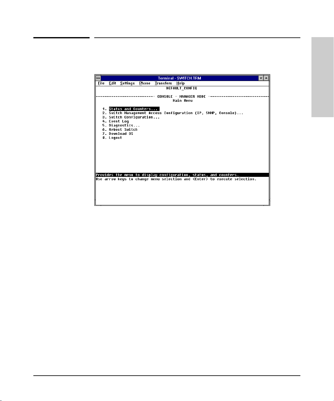
Figure 1-2. Example of the Console Interface Display
■ Contains a complete set of features and parameters
■ Out-of-band access (through RS-232 connection) to switch, so network
bottlenecks, crashes, lack of configured or correct IP address, and
network downtime do not slow or prevent access
■ Ability to configure management access, for example, creating an IP
address, and setting Community Names and Authorized Managers
■ Telnet access to the full console functionality
■ Faster navigation, avoiding delays that occur with slower display of
graphical objects over a web browser interface
■ More secure; configuration information and passwords are not seen on
the network
1-3
Page 20
Selecting a Management Interface
Advantages of Using HP TopTools for Hubs & Switches
Advantages of Using HP TopTools for
Hubs & Switches
Interface
Selecting a Management
You can operate HP TopTools from a PC on the network to monitor traffic,
manage your hubs and switches, and proactively recommend network
changes to increase netwo rk uptime and optimize performance. Easy to install
and use, HP TopTools for Hubs & Switches is the answer to your management
challenges.
1-4
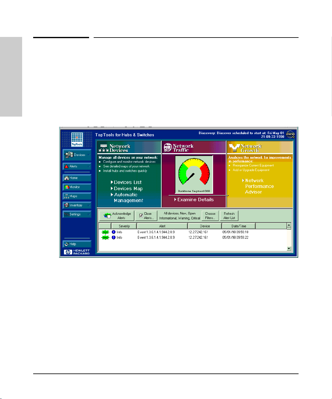
Figure 1-3. Example of HP TopTools Main Screen
HP TopTools for Hubs& Switches has three main sections: Network Devices,
Network Traffic, and Network Growth:
Network Devices
■ Enables fast installation of hubs and switches.
■ Quickly finds and notifies you of the location of problems, saving valuable
time.
■ Notifies you when HP hubs use “self-healing” features to fix or limit
common network problems.
Page 21

Advantages of Using HP TopTools for Hubs & Switches
Selecting a Management Interface
■ Identifies users by port and lets you assign easy-to-remember names to
any network device.
■ Enables you to configure and monitor network devices from your PC.
Network Traffic
■ Watches the network for problems.
■ Shows traffic and “top talker” nodes on screen.
■ Uses traffic monitor diagrams to make bottlenecks easy to see.
■ Improves network reliability through real-time fault isolation.
■ See your entire network without having to put RMON probes on every
segment (up to 1500 segments).
Network Growth
■ Monitors, stores, and analyzes network traffic to determine where
upgrades are needed.
■ Uses Network Performance Advisor to give clear, easy-to-follow plans
detailing the most cost-effective way to upgrade your network.
Selecting a Management
Interface
1-5
Page 22

Page 23

Configuring an IP Address on the Switch
This chapter helps you to quickly assign an IP (Internet Protocol) address and
subnet mask to the switch. In the factory default configuration, the switch
does not have an IP address and subnet mask, so it can be managed only by
using a direct connection to the switch console.
2
Configuring an IP (Internet Protocol) address and subnet mask enables the
switch to operate as a managed device in your network, giving you in-band
(networked) access to these interfaces:
■ HP web browser interface built into the switch
■ HP TopTools for Hubs & Switches—SNMP-based network management
software shipped with the switch
■ the switch console through a telnet connection
For a listing of switch features available with and without an IP address, refer
to “How IP Addressing Affects Switch Operation” on page 6-8.
For more information on this topic, refer to “IP Configuration” on page 6-4.
Note The IP address and subnet mask assigned for the switch should be compatible
with the IP addressing used in your network. If your network is a standalone
network, your IP addressing and subnet mask scheme can be set up in any
way that meets your local needs. However, if you will be connecting your
network to other networks that use globally assigned IP addresses, refer to
“Globally Assigned IP Network Addresses” on page 6-13.
Configuring an IP Address
on the Switch
2-1
Page 24

Configuring an IP Address on the Switch
Methods for Configuring an IP Address and Subnet Mask
Methods for Configuring an IP Address
and Subnet Mask
If the switch has not already been configured with an IP address and subnet
mask compatible with your network, use either of the following two methods
to do so:
■ Manually through the switch console: This is the easiest method if you
have direct-connect or modem access to a terminal emulator on a PC
(such as HyperTerminal in Windows 95 or Windows NT), or a direct
connection to a VT-100 terminal. Refer to “Manually Configuring an IP
Address” below.
■ Configure your DHCP/Bootp server to support the switch: By
default, the switch is configured to acquire an IP address configuration
from a DHCP or Bootp server. To use DHCP/Bootp, refer to “DHCP/Bootp
Operation” on page 6-9.
on the Switch
Configuring an IP Address
Manually Configuring an IP Address
This section describes how to use the switch console to configure an IP
address. The following assumes that no VLANs have been configured on the
switch.
Note In its factory default configuration, all ports on the switch belong to one,
default virtual LAN (VLAN), and only one IP address is needed. If you
configure the switch with more than one VLAN, each VLAN may have its own
IP address. For more on VLANs, refer to “Port-Based Virtual LANs (VLANs)”
on page 6-51.
1. Use the instructions in your switch installation manual to connect a PC
running a terminal emulator, or a terminal, to the Console port on the
switch, and display the Main Menu.
2. From the Main Menu, select
2. Switch Management Access Configuration
1. IP Configuration
You will see a screen similar to the one shown in figure 2-1.
2-2
Page 25
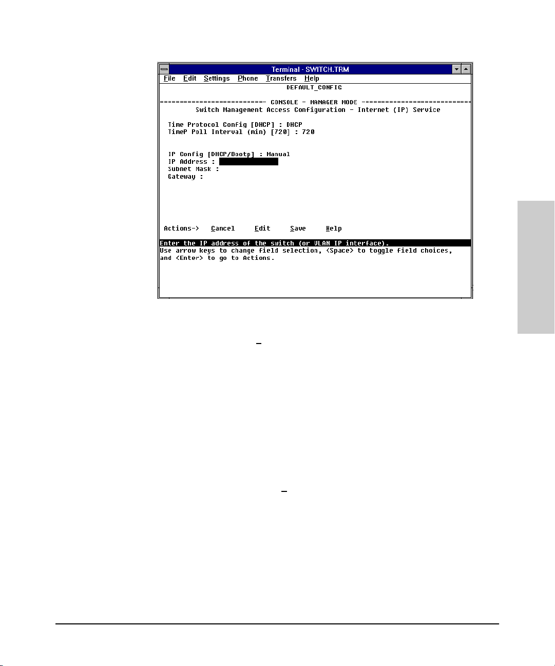
Figure 2-1. The Internet (IP) Service Screen
Configuring an IP Address on the Switch
Manually Configuring an IP Address
Configuring an IP Address
on the Switch
3. Press [E] to select E
dit, then use the down arrow key ([v]) to select
IP Config [DHCP/BOOTP].
4. Use the Space bar to display Manual for this field.
5. Press the down arrow key ([v]) to display the three IP configuration
parameters and select the IP Address field.
6. Enter the IP address you want to assign to the switch.
7. Select the Subnet Mask field and enter the subnet mask for your network.
8. If you want to reach off-subnet destinations, select the Gateway field and
enter the address of the gateway router for your subnet.
9. Press [Enter], then [S] (for S
ave), then proceed with any other console tasks.
2-3
Page 26

Configuring an IP Address on the Switch
Manually Configuring an IP Address
on the Switch
Where To Go From Here
The above procedure configures your switch with an IP address and subnet
mask. With the proper network connections, you can now manage the switch
from a network management station or from a PC equipped with a web
browser.
■ To access the switch using a web browser, refer to chapter 3, “Using the
HP Web Browser Interface”.
■ To continue to use the console interface, refer to chapter 4, “Using the
Switch Console Interface”.
■ To access the switch using a network management tool, refer to chapter
5, “Using HP TopTools or Other SNMP Tools to Monitor and Manage the
Switch”.
■ Inbound telnet access to the switch is enabled in the factory default.
• To change the current telnet access parameter, turn to “Configuring
the Console/Serial Link from the Switch Console” on page 6-20.
• To use telnet to access the switch console, refer to “Starting and
Ending a Console Session” on page 4-2.
Configuring an IP Address
You can also start a telnet session to the switch console from the web
browser interface. Click on the Configuration tab in the web browser
interface, then click on telnet session to the switch console. If you need
information on how to access the switch via the web browser interface, refer to chapter 3, “Using the HP Web Browser Interface”.
■ For problems or error indications, refer to chapter 8, “Troubleshooting”.
2-4
Page 27

Using the HP Web Browser Interface
Overview
The HP web browser interface built into the switch lets you easily access the
switch from a browser-based PC on your network. This lets you do the
following:
■ optimize your network uptime by using the Alert Log and other diagnostic
tools
■ make configuration changes to the switch
■ maintain security by configuring usernames and passwords
Using the web browser interface to configure the switch is covered in chapter
6, “Configuring the Switch”. This chapter covers the following:
■ system requirements for using the web browser interface (page 3-2)
■ starting a web browser interface session (page 3-3)
■ tasks for your first web browser interface session (page 3-6):
• creating usernames and passwords in the web browser interface
(page 3-8)
• selecting the fault detection configuration for the Alert Log operation
(page 3-27)
• getting access to online help for the web browser interface (page 3-10)
■ description of the web browser interface:
• the Overview window and tabs (page 3-14)
• the Port Utilization and Status displays (page 3-16)
• the Alert Log and Alert types (page 3-18)
• setting the Fault Detection Policy (page 3-27)
3
Using the HP Web Browser
Interface
Note If you want security beyond that achieved with user names and passwords,
you can disable access to the web browser interface. This is done by changing
the Web Agent Enabled parameter setting in the Serial Link configuration
screen in the switch console. See “Console/Serial Link” on page 6-19.
3-1
Page 28
Using the HP Web Browser Interface
Web Browser Interface Requirements
Web Browser Interface Requirements
You can use equipment meeting the following requirements to access the web
browser interface on your intranet.
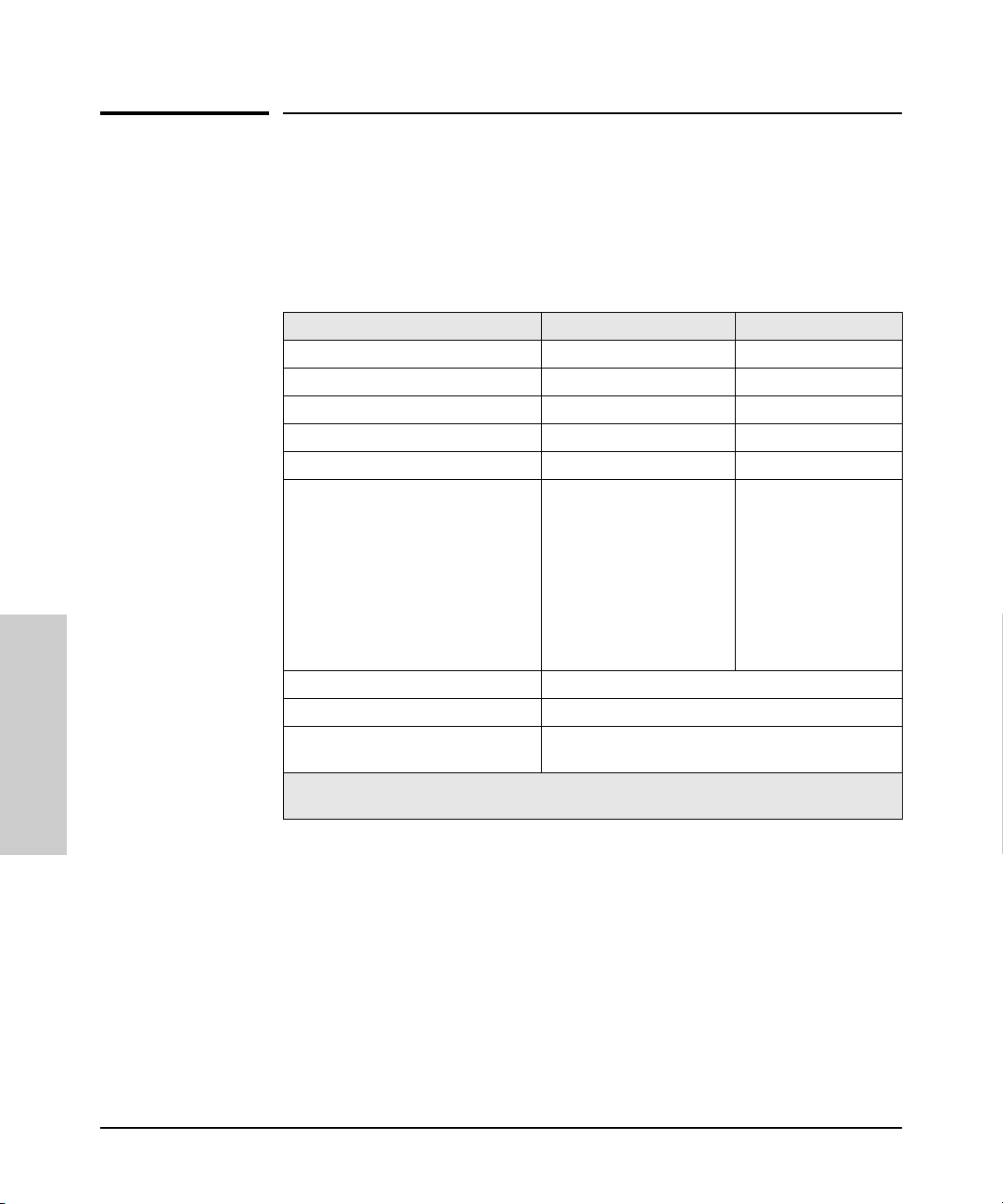
Table 3-1. System Requirements for Accessing the HP Web Browser Interface
Platform Entity and OS Version Minimum Recommended
PC Platform 90 MHz Pentium 120 MHz Pentium
HP-UX Platform (9.x or 10.x) 100 MHz 120 MHz
RAM 16 Mbytes 32 Mbytes
Screen Resolution 800 X 600 1,024 x 768
Color Count 256 65,536
Internet Browser
(English-language browser only)
PC Operating System Microsoft Windows® 95 and Windows NT
UNIX® Operating System Standard UNIX® OS
HP TopTools for Hubs & Switches
Interface
(Optional)
*
For notes on using Netscape and Microsoft web browsers, go to HP’s ProCurve Networking
web site, http://www.hp.com/go/procurve.
*
PCs:
• Netscape®
Communicator 4.x
• Microsoft® Internet
Explorer 4.x
UNIX: Netscape Navigator
3.1 or later
use product HP J2569M or later
Using the HP Web Browser
PCs:
• Netscape
Communicator 4.03
or later
• Microsoft® Internet
Explorer 4.01, SP1 or
later
UNIX: Netscape
Navigator 4.03 or later
3-2
Page 29

Starting an HP Web Browser Interface Session with the Switch
Using the HP Web Browser Interface
Starting an HP Web Browser Interface
Session with the Switch
You can start a web browser session in the following ways:
■ Using a standalone web browser on a network connection from a PC or
UNIX workstation:
• directly connected to your network.
• connected through remote access to your network.
■ Using a management station running HP TopTools for Hubs & Switches
on your network.
Note HP TopTools is designed for installation on a network management worksta-
tion. For this reason, the HP TopTools system requirements are different from
the system requirements for accessing the switch’s web browser interface
from a non-management PC or workstation. For HP TopTools requirements,
refer to the information printed on the sleeve in which the HP TopTools CD is
shipped, or to the system requirements information in the user’s guide
included on the HP TopTools CD.
Using a Standalone Web Browser in a PC or UNIX Workstation
This procedure assumes that you have a supported web browser (page 3-2)
installed on your PC or workstation, and that an IP address has been configured on the switch. (For more on assigning an IP address, refer to chapter 2,
“Configuring an IP Address on the Switch”.)
TM
1. Make sure the Java
not, do one of the following:
• In Netscape 4.03, click on E
Enable Java and Enable JavaScript options.
• In Microsoft Internet Explorer 4.x, click on View, Internet O
Security, C
to the online Help for specific information on enabling the Java
applets.
ustom, [Settings] and scroll to the Java Permissions. Then refer
applets are enabled for your browser. If they are
dit, Preferences..., Advanced, then select
ptions,
3-3
Using the HP Web Browser
Interface
Page 30

Using the HP Web Browser Interface
Starting an HP Web Browser Interface Session with the Switch
2. Type the IP address (or DNS name) of the switch in the browser Location
or Address field and press [Enter]. (It is not necessary to include
http://.)
switch4000 [Enter] (example of a DNS-type name)
10.11.12.195 [Enter] (example of an IP address)
If you are using a Domain Name Server (DNS), your device may have a
name associated with it (for example, switch4000) that you can type in the
Location or Address field instead of the IP address. Using DNS names
typically improves browser performance. See you r network administrator
for any name associated with the switch.
The web browser interface automatically starts with the Status Overview
window displayed for the selected device as shown in figure 3-1 on page
3-5.
Using HP TopTools for Hubs & Switches
For information on HP TopTools web browser and system requirements, refer
to the information printed on the sleeve in which the HP TopTools CD is
shipped, or to the system requirements information in the user’s guide
included on the HP TopTools CD.
This procedure assumes that:
■ You have installed the web browser recommended for HP TopTools on a
PC or workstation that serves as your network management station.
■ The networked device you want to access has been assigned an IP address
and (optionally) a DNS name and has been discovered by HP TopTools.
Interface
(For more on assigning an IP address, refer to chapter 2, “Configuring an
IP Address on the Switch”.)
To establish a web browser session with HP TopTools running, do the
Using the HP Web Browser
following on the network management station:
TM
1. Make sure the Java
applets are enabled for your web browser. If they
are not, refer to the web browser online Help for specific information on
enabling the Java applets.
2. Do one of the following tasks:
• On the HP TopTools Maps view, double-click on the symbol for the
networking device that you want to access.
• In HP TopTools, in the Topology Information dialog box, in the device
list, double-click on the entry for the device you want to access (IP
address or DNS name).
3-4
Page 31
First-Time
Install Alert
Alert Log
Starting an HP Web Browser Interface Session with the Switch
Using the HP Web Browser Interface
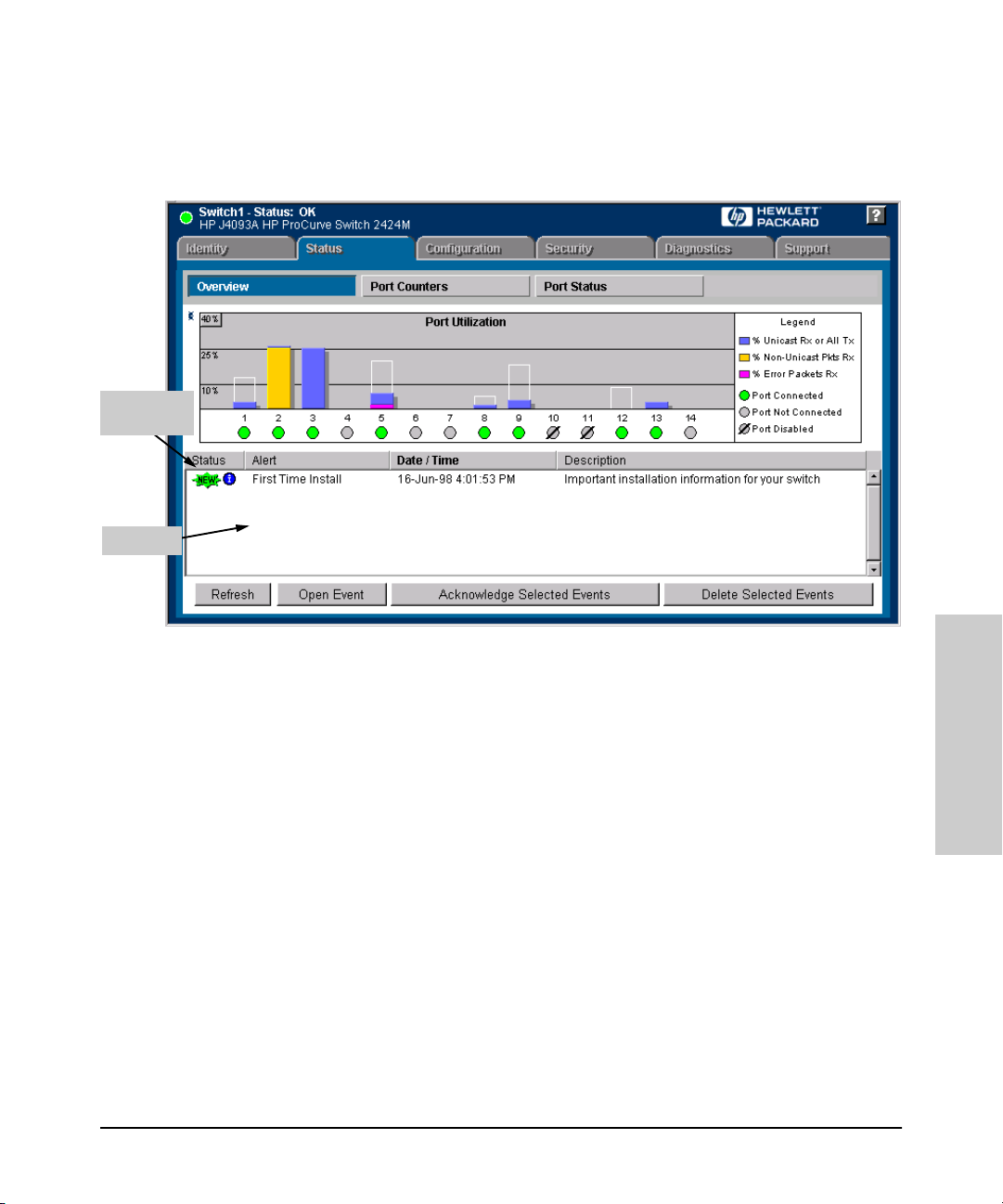
3. The web browser interface automatically starts with the Status Overview
window displayed for the selected device, as shown in figure 3-1.
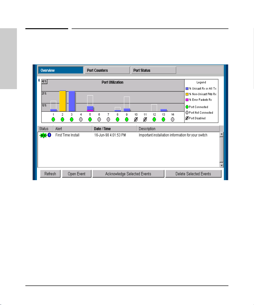
Figure 3-1. Status Overview Screen
Using the HP Web Browser
Interface
3-5
Page 32

Using the HP Web Browser Interface
Tasks for Your First HP Web Browser Interface Session
Tasks for Your First HP Web Browser
Interface Session
The first time you access the web browser interface, there are three tasks that
you should perform:
■ Review the “First Time Install” window
■ Set Manager and Operator passwords
■ Set access to the web browser interface online help
Viewing the “First Time Install” Window
When you access the switch’s web browser interface for the first time, the
Alert log contains a “First Time Install” alert, as shown in figure 3-1. This gives
you information about first time installations, and provides an immediate
opportunity to set passwords for security and to specify a Fault Detection
policy, which determines the types of messages that will be displayed in the
Alert Log.
Double click on First Time Install in the Alert log (see above). The web browser
interface then displays the “First Time Install” window, as shown in figure 3-2.
Interface
Using the HP Web Browser
Figure 3-2. First-Time Install Window
3-6
Page 33

Tasks for Your First HP Web Browser Interface Session
Using the HP Web Browser Interface
This window is the launching point for the basic configuration you need to
perform to set web browser interface passwords to maintain security and
Fault Detection policy, which determines the types of messages that will be
displayed in the Alert Log.
To set web browser interface passwords, click on the jump string secure
access to the device to display the Device Passwords screen, and then go to
the next page. You can also access the password screen by clicking on the
Security tab.
To set Fault Detection policy, click on the jump string select the fault detection
configuration in the second bullet in the window and go to the section, “Setting
Fault Detection Policy” on page 3-27.
3-7
Using the HP Web Browser
Interface
Page 34

Using the HP Web Browser Interface
Tasks for Your First HP Web Browser Interface Session
Creating Usernames and Passwords in the Browser Interface
You may want to create both a username and password to create access
security for your switch. There are two levels of access to the interface that
can be controlled by setting user names and passwords:
■ Operator. An Operator-level user name and password allows read-only
access to most of the web browser interface, but prevents access to the
Security window.
■ Manager. A Manager-level user name and password allows full read/
write access to the web browser interface.
Interface
Using the HP Web Browser
Figure 3-3. The Device Passwords Window
To set the passwords:
1. Access the Device Passwords screen by one of the following methods:
• If the Alert Log includes a “First Time Install” event entry, double
click on this event, then, in the resulting display, click on the
secure access to the device link.
• Select the Security tab.
3-8
Page 35

Tasks for Your First HP Web Browser Interface Session
Using the HP Web Browser Interface
2. Click in the appropriate box in the Device Passwords window and enter
user names and passwords. You will be required to repeat the password
strings in the confirmation boxes.
Both the user names and passwords can be up to 16 printable ASCII
characters.
3. Click on [Apply Changes] to activate the user names and passwords.
Note Strings you assign in the web browser interface will overwrite previous access
strings assigned in either the web browser interface or the switch console.
Using the Passwords
The manager and operator passwords are used to control access to both the
web browser interface and the switch console. Once set, you will be challenged to supply the password every time you try to access either the web
browser interface or switch console. The password you enter determines the
capability you have during that session:
■ Entering the manager password gives you full read/write capabilities
■ Entering the operator password gives you read and limited write capabil-
ities.
Using the User Names
If you also set user names in the web browser interface screen, you must
supply the correct user name for web browser interface access, but switch
console access requires only the password. If a user name has not been set,
you must leave the User Name field in the web browser interface access popup
blank.
The switch console uses only the passwords and does not prompt you for the
User Names.
If You Lose a Password
If you lose the passwords, you can clear them by pressing the Clear button on
the front of the switch. This action deletes all password and user name
protection for both the web browser interface and the switch console.
The Clear button is provided for your convenience, but its presence means
that if you are concerned with the security of the switch configuration and
operation, you should make sure the switch is installed in a secure location,
such as a locked wiring closet.
3-9
Using the HP Web Browser
Interface
Page 36

Using the HP Web Browser Interface
Tasks for Your First HP Web Browser Interface Session
Online Help for the HP Web Browser Interface
Online Help is available for the web browser interface. You can use it by
clicking on the question mark in the upper right corner of any of the web
browser interface screens. Context-sensitive help is provided for the screen
you are on.
Providing Online Help. The Help files are automatically available if you
install HP TopTools for Hubs & Switches on your network or if you already
have Internet access to the World Wide Web. (The Help files are included with
HP TopTools for Hubs & Switches, and are also automatically available from
HP via the World Wide Web.)
Retrieval of the Help files as described above is controlled by automatic
entries to the Management Server URL field on the Configuration / Support URLs
screen, shown in figure 3-4. The switch is shipped with the URL set to retrieve
online Help from the HP World Wide Web site. However, if HP TopTools for
Hubs & Switches is installed on a management station on your network and
discovers the switch, the Management Server URL is automatically changed
to retrieve the Help from your TopTools management station.
If Online Help Fails To Operate. Do one of the following:
■ If HP TopTools for Hubs & Switches is installed and running on your
network, enter the IP address or DNS name of the network management
station in the Management Server URL field shown in figure 3-4 on page
3-11.
■ If you have World Wide Web access from your PC or workstation, and do
not have HP TopTools installed on your network, enter the following URL
Interface
in the Management Server URL field shown in figure 3-4 on page 3-11:
http://www.hp.com/rnd/device_help
Using the HP Web Browser
3-10
Page 37

Tasks for Your First HP Web Browser Interface Session
Enter IP address of HP TopTools network
management station, or URL of location of
help files on HP’s World Wide Web site here.
Using the HP Web Browser Interface
Figure 3-4. How To Access Web Browser Interface Online Help
If you do not have HP TopTools for Hubs and Switches installed on your
network and do not have an active connection to the World Wide Web, then
Online help for the web browser interface will not be available.
See also “Support URLs Feature” on the next page.
Using the HP Web Browser
Interface
3-11
Page 38

Using the HP Web Browser Interface
Support URLs Feature
Support URLs Feature
The Support/Mgmt URLs window enables you to change the World Wide Web
Universal Resource Locator (URL) for two functions:
■ Support URL – a support information site for your switch
■ Management Server URL – the site for online help for the web browser
interface, and, if set up, the URL of a network management station running
HP TopTools for Hubs & Switches.
1. Click Here
3. Enter URLs for:
- the support information source that is accessed when
you click on the web browser interface Support tab – the
default is HP’s ProCurve network products World Wide Web
home page
- the URL of the network Management server or other
Interface
source of the online help files for this web browser inter face. (The default is a location on HP’s World Wide Web site.)
2. Click Here
4. Click on Apply Change s
Using the HP Web Browser
Figure 3-5. The Default Support/Mgmt URLs Window
Support URL
This is the site that will be accessed when you click on the Support tab on the
web browser interface. The default URL is:
3-12
http://www.hp.com/go/procurve
which is the World Wide Web site for Hewlett-Packard’s networking products.
Page 39

Using the HP Web Browser Interface
Support URLs Feature
Click on the [Support] button on that page and you can get to support information
regarding your switc h, including white papers, operating system (OS) updates,
and more.
You could instead enter the URL for a local site that you use for entering
reports about network performance, or whatever other function you would
like to be able to easily access by clicking on the [Support] tab.
Management Server URL
This field specifies which of the following two locations the switch will use to
find online Help for the web browser interface:
■ The URL of online Help provided by HP on the world wide web
■ The URL of a network management station running HP TopTools for Hubs
& Switches
The default URL is:
http://www.hp.com/rnd/device_help
which is the location on HP’s World Wide Web site of the help files for the web
browser interface. To use this site, you must have a modem link or other access
to the World Wide Web operating when you run the web browser interface.
Then, when you click on the
screens, the context sensitive help for that screen will be retrieved from HP.
[?] button on any of the web browser interface
Using the HP Web Browser
Alternatively, if you install HP TopTools for Hubs & Switches on your network
and TopTools discovers your switch, it automatically overwrites the Management Server URL field with the address or name of the TopTools management
station. In this case, online help will automatically be provided from the
network management station. Refer to “Online Help for the HP Web Browser
Interface” on page 3-10.
Additionally, HP Top Tools for Hubs & Switches has the capability to perform
network-wide policy management and configuration of your switch. This field
identifies the management station that is performing that function. For more
information, refer to the documentation provided on the HP TopTools CD
shipped with the switch.
3-13
Interface
Page 40

Using the HP Web Browser Interface
The Web Browser Interface Screen Layout
The Web Browser Interface Screen
Layout
This section describes the elements of the web browser interface screen
layout starting with the first screen you see, the Status, Overview window.
The Overview Window
The Overview Window is the home screen for any entry into the web browser
interface.The following figure identifies the various parts of the screen.
Status Bar
Tab Bar
Button Bar
Port
Utilization
Graphs
Port Status
Indicators
Alert Log
Interface
Using the HP Web Browser
Header Bar
Alert Log
Control Bar
Active Button
Active Tab
Alert Log
Figure 3-6. The Overview Window
3-14
The areas and fields in the web browser interface Overview Window are
described on the next page.
Page 41

Using the HP Web Browser Interface
The Web Browser Interface Screen Layout
■ Tab B a r. The row of tabs displaying all the top level menus for the web
browser interface.
■ Active Tab. The current tab selected. The tab is darkened and all the
buttons under the tab are displayed.
■ Status Bar. The region above the Tab Bar that displays status and device
name information.
■ Port Utilization and Status Displays. The region containing graphs
that indicate network traffic on each switch port and symbols indicating
the status of each port.
■ Button Bar. The row of buttons that are contained within the Active Tab.
■ Active Button. The current button selected. The button is darkened and
the window associated with the button is displayed.
■ Alert Log. A list of all events, or alerts, that can be retrieved from the
switch’s firmware at the current time. Information associated with the
alerts is displayed, including Status, Alert Name, the date and time the
Alert was reported by the switch, and a short description of the alert. You
can double click on any of the entries in the log and get a detailed
description. See “The Alert Log” on page 3-18.
■ Alert Log Header Bar. The row of column heads running across the top
of the Alert Log.
■ Alert Log Control Bar. The region at the bottom of the Alert Log
containing buttons that enable you to refresh the Alert Log to display all
alerts that have been reported since you first displayed the log. Also
available in the bar are a button to acknowledge new alerts and a button
to delete alerts.
Using the HP Web Browser
Interface
3-15
Page 42
Using the HP Web Browser Interface
The Web Browser Interface Screen Layout
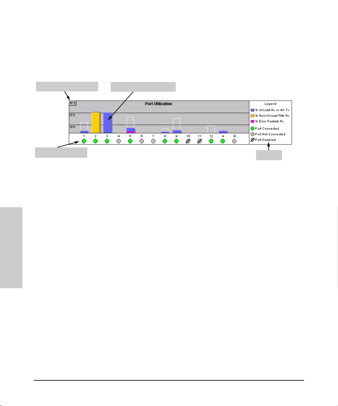
The Port Utilization and Status Displays
The Port Utilization and Status displays show an overview of the status of the
switch and the amount of network activity on each port. The following figure
shows a sample reading of the Port Utilization and Port Status.
Bandwidth Display Control
Port Status Indicators
Port Utilization Bar Graphs
Legend
Figure 3-7. The Graphs Area
Port Utilization
The Port Utilization bar graphs show the network traffic on the port with a
breakdown of the packet types that have been detected (unicast packets, nonunicast packets, and error packets). The Legend identifies traffic types and
their associated colors on the bar graph:
■ % Unicast Rx & All Tx: This is all unicast traffic received and all
transmitted traffic of any type. This indicator (a blue color on many
systems) can signify either transmitted or received traffic.
Interface
Using the HP Web Browser
■ % Non-Unicast Pkts Rx: All multicast and broadcast traffic received by
the port. This indicator (a gold color on many systems) enables you to
know “at-a-glance” the source of any non-unicast traffic that is causing
high utilization of the switch. For example, if one port is receiving heavy
broadcast or multicast traffic, all ports will become highly utilized. By
color-coding the received broadcast and multicast utilization, the bar
graph quickly and easily identifies the offending port. This makes it faster
and easier to discover the exact source of the heavy traffic because you
don’t have to examine port counter data from several ports.
■ % Error Pkts Rx: All error packets received by the port. (This indicator
is a reddish color on many systems.) Although errors received on a port
are not propagated to the rest of the network, a consistently high number
of errors on a specific port may indicate a problem on the device or
network segment connected to the indicated port.
3-16
Page 43
Using the HP Web Browser Interface
The Web Browser Interface Screen Layout
A network utilization of 40% is considered the maximum that a typical
Ethernet-type network can experience before encountering performance
difficulties. If you observe utilization that is consistently higher than 40% on
any port, click on the Port Counters button to get a detailed set of counters
for the port.
■ Maximum Activity Indicator: As the bars in the graph area change
height to reflect the level of network activity on the corresponding port,
they leave an outline to identify the maximum activity level that has been
observed on the port.
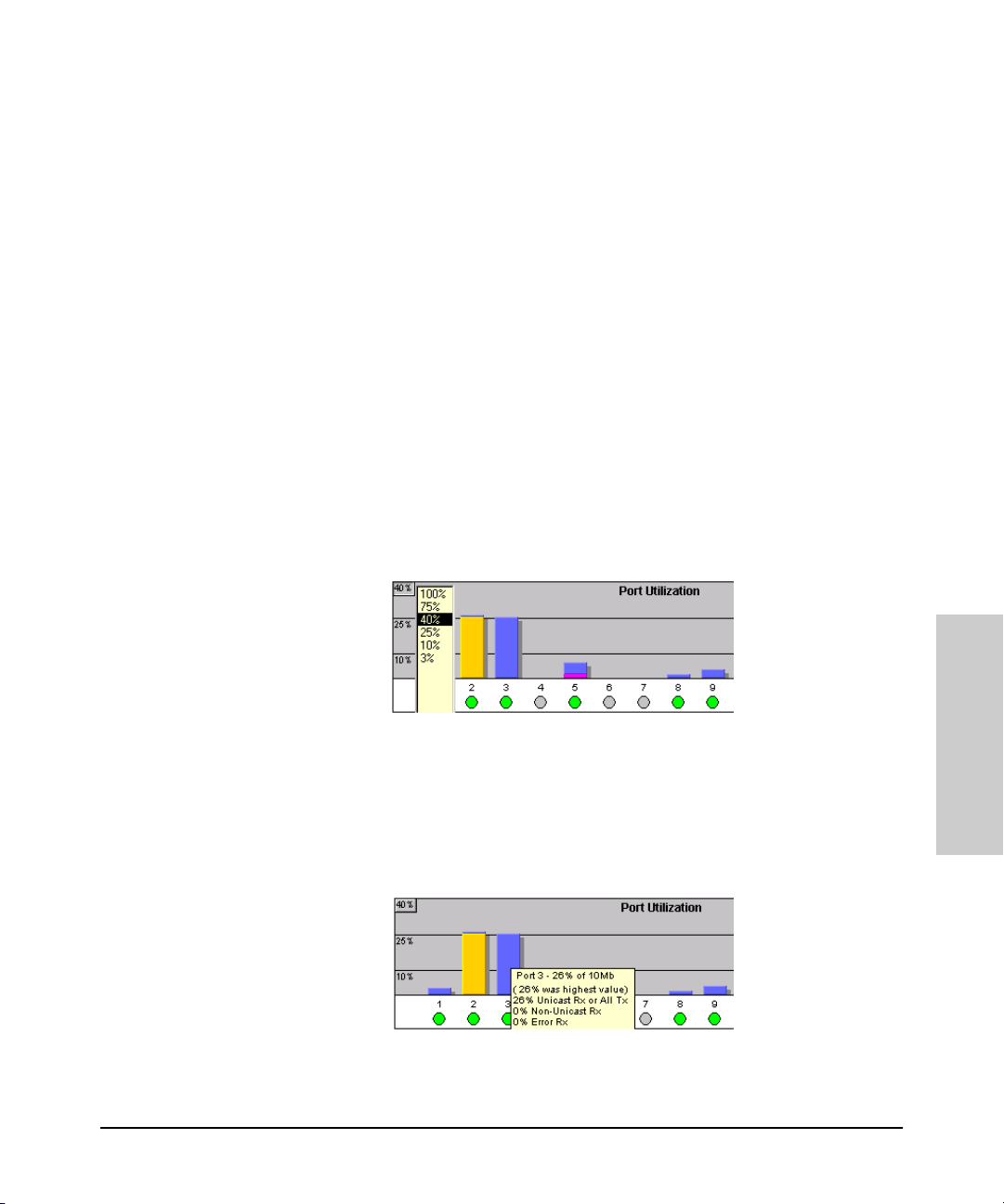
To change the amount of bandwidth the Port Utilization bar graph
shows. Click on the bandwidth display control button in the upper left corner
of the graph. (The button shows the current scale setting, such as 40%.) In the
resulting menu, select the bandwidth scale you want the graph to show (3%,
10%, 25%, 40%, 75%, or 100%), as shown in figure 3-7.
Note that when viewing activity on a gigabit port, you may want to select a
lower value (such as 3% or 10%). This is because the bandwidth utilization of
current network applications on gigabit links is typically minimal, and may
not appear on the graph if the scale is set to show high bandwidth utilization.
Figure 3-8. Changing the Graph Area Scale
To display values for each graph bar. Hold the mouse cursor over any of
the bars in the graph, and a pop-up display is activated showing the port
identification and numerical values for each of the sections of the bar, as
shown in figure 3-8.
Figure 3-9. Display of Numerical Values for the Bar
3-17
Using the HP Web Browser
Interface
Page 44

Using the HP Web Browser Interface
The Web Browser Interface Screen Layout
Port Status
The Port Status indicators show a symbol for each port that indicates the
general status of the port. There are four possible statuses:
■ Port Connected – the port is enabled and is properly connected to an
active network device.
■ Port Not Connected – the port is enabled but is not connected to an
active network device. A cable may not be connected to the port, or the
device at the other end may be powered off or inoperable, or the cable or
connected device could be faulty.
■ Port Disabled – the port has been configured as disabled through the
web browser interface, the switch console, or SNMP network management.
■ Port Fault-Disabled – a fault condition has occurred on the port that
has caused it to be auto-disabled. Note that the Port Fault-Disabled
symbol will be displayed in the legend only if one or more of the ports is
in that status. See chapter 7, “Monitoring and Analyzing Switch Operation”
for more information.
The Alert Log
The web browser interface Alert Log, shown in the lower half of the screen,
shows a list of network occurrences, or alerts, that were detected by the
switch. Typical alerts are, Broadcast Storm, indicating an excessive number of
broadcasts received on a port, and Problem Cable, indicating a faulty cable. A
full list of alerts is shown in the table on page 3-20.
Interface
Using the HP Web Browser
3-18
Page 45

Using the HP Web Browser Interface
The Web Browser Interface Screen Layout
Figure 3-10. The Alert Log
Each alert has the following fields of information:
■ Status – The level of severity of the event generated. Severity levels can
be Information, Normal, Warning, and Critical. If the alert is new (has not
yet been acknowledged), the New symbol is also in the Status column.
■ Alert – The specific event identification.
■ Date/Time – The date and time the event was received by the web
browser interface. This value is shown in the format:
HH:MM:SS
■ Description – A short narrative statement that describes the event. For
AM/PM, for example, 16-Sep-99 7:58:44 AM.
DD-Mon-YY
example, Excessive CRC/Alignment errors on port: 8.
Using the HP Web Browser
Sorting the Alert Log Entries
The alerts are sorted, by default, by the Date/Time field with the most recent
alert listed at the top of the list. The second most recent alert is displayed
below the top alert and so on. If alerts occurred at the same time, the
simultaneous alerts are sorted by order in which they appear in the MIB.
The alert field that is being used to sort the alert log is indicated by which
column heading is in bold. You can sort by any of the other columns by clicking
on the column heading. The Alert and Description columns are sorted alphabetically, while the Status column is sorted by severity type, with more critical
severity indicators appearing above less critical indicators.
3-19
Interface
Page 46

Using the HP Web Browser Interface
The Web Browser Interface Screen Layout
Alert Types
The following table lists the types of alerts that can be generated.
Table 3-2. Alert Strings and Descriptions
Alert String Alert Description
First Time Install Important installation information for your switch.
Too many undersized/giant packets A device connected to this port is transmitting packets shorter than 64 bytes or
Excessive jabbering A device connect ed to this port is in cessantly transmitting packets (“jabbering”) ,
Excessive CRC/alignment errors A high percentage of data errors has been detected on this port. Possible causes
Excessive late collisions Late collisions (collisions detected after transmitting 64 bytes) have been
High collision or drop rate A large number of collisions or packet drops have occurred on the port. Possible
Interface
Using the HP Web Browser
longer than 1518 bytes (longer than 1522 bytes if tagged), with valid CRCs (unlike
runts, which have invalid CRCs).
detected as oversized packets with CRC errors.
include:
• Faulty cabling or invalid topology.
• Duplex mismatch (full-duplex configured on one end of the link, half-duplex
configured on the other)
• A malfunctioning NIC, NIC driver, or transceiver
detected on this port. Possible causes include:
• An overextended LAN topology
• Duplex mismatch (full-duplex configured on one end of the link, half-duplex
configured on the other)
• A misconfigured or faulty device connected to the port
causes include:
• A extremely high level of traffic on the port
• Duplex mismatch
• A misconfigured or malfunctioning NIC or transceiver on a device connected
to this port
• A topology loop in the network
Excessive broadcasts An extremely high percentage of broadcasts was received on this port. This
Network Loop Network loop has been detected by the switch.
Loss of Link Lost connection to one or multiple devices on the port.
degrades the p erformance of all devices connected to the port . Possible causes
include:
• A network topology loop—this is the usual cause
• A malfunctioning device, NIC, NIC driver, or software package
3-20
Page 47
Using the HP Web Browser Interface
The Web Browser Interface Screen Layout
Note When troubleshooting the sources of alerts, it may be helpful to check the
switch’s Port Status and Port Counter windows (page 7-8 and page 7-10) and
the Event Log in the console interface (page 8-12).
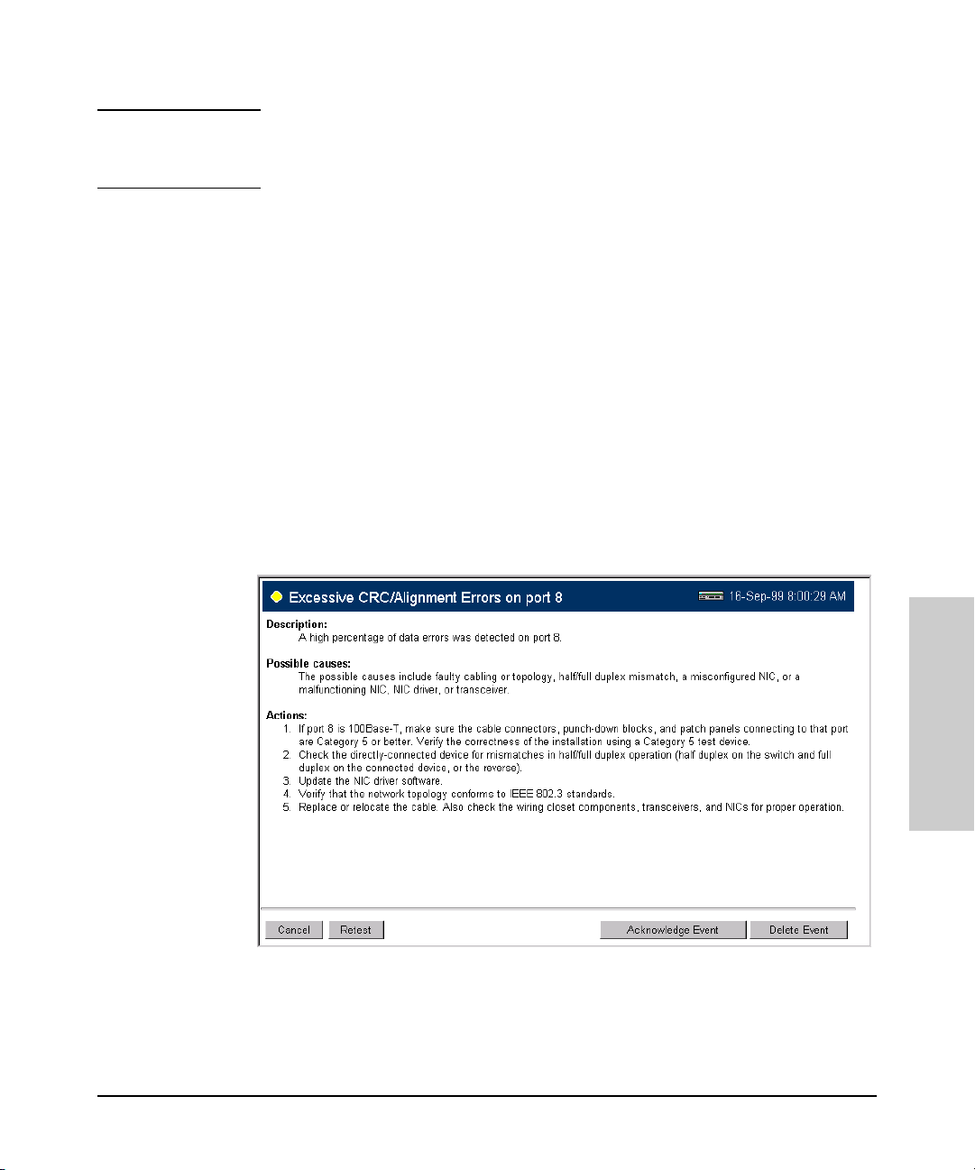
Viewing Detail Views of Alert Log Entries
By double clicking on Alert Entries, the web browser interface displays a
Detail View or separate window detailing information about the events. The
Detail View contains a description of the problem and a possible solution. It
also provides four management buttons:
■ Acknowledge Event – removes the New symbol from the log entry
■ Delete Event – removes the alert from the Alert Log
■ Retest Button – polls the switch again to determine whether or not the
alert can be regenerated.
■ Cancel Button – closes the detail view with no change to the status of
the alert and returns you to the Overview screen.
A sample Detail View describing an Excessive CRC/Alignment Error alert is
shown here.
Figure 3-11. Alert Log Detail View
Using the HP Web Browser
Interface
3-21
Page 48

Using the HP Web Browser Interface
The Web Browser Interface Screen Layout
The Alert Control Bar
The Alert Control Bar appears at the bottom of the Alert Log and contains
buttons that enable you to manage the Overview Window.
The buttons in the control bar are:
■ Refresh – redraws the Alert Log screen and displays new alerts that have
occurred since you opened or last refreshed this window.
■ Open Event – displays the detailed view of the highlighted alert; the same
as double-clicking on the alert.
■ Acknowledge Selected Events – removes the New symbol from the
entry. This feature is useful if you have more than one system administrator working on a problem. It shows that someone has looked at it.
If an alert has not been acknowledged, the New label continues to appear
in the Status column to the left of the Status Indicator. Once the alert has
been acknowledged from either the Alert Log screen or the Detailed View
screen, the New label is removed.
■ Delete Selected Events – removes an alert from the Alert Log.
Interface
Using the HP Web Browser
3-22
Page 49

Using the HP Web Browser Interface
The Web Browser Interface Screen Layout
The Tab Bar
The Tab bar in the web browser interface contains six tabs, four of which
launch button bars which launch specific functional windows. One tab, Identity, launches a dedicated functional window with no buttons. Another tab,
Support, launches a separate web page with support information.
To navigate through the different features of the web browser interface, click
on the appropriate tab in the Tab Bar. The tabs are as follows:
Identity Tab
This tab displays the Identity Window which is a source of quick information
about the switch.
■ Editable Information (System Name, Location, and Contact) – is
maintained in the Administration dialog box.
■ Read-Only Information – The System Up Time shows the elapsed time
since the switch was last rebooted. Product is the switch product name.
Version is the software (operating system) version currently running in the
switch. IP Address is the IP address assigned to the switch. Management
Server is the currently assigned Management Server URL (page 3-12).
Using the HP Web Browser
Status Tab
This tab displays the Status Button bar which contains buttons that display
switch settings and statistics that represent recent switch behavior. The
buttons are:
■ Overview – the home position for the web browser interface. Displays
the screen shown in figure 3-6.
■ Port Counters – displays a summary of the network activity statistics
for all the switch ports, with access to detailed port-level statistics
■ Port Status – displays a summary table of the operational status of all
the switch ports
3-23
Interface
Page 50

Using the HP Web Browser Interface
The Web Browser Interface Screen Layout
Configuration Tab
This tab displays the Configuration Button bar which contains buttons that
launch screens for setting or changing some of the switch configuration. The
buttons are:
■ Device View. Displays a graphical representation of the front panel of the
device, allowing you enable and disable ports on the device by clicking
on port graphics and an enable or disable port button. This view also lets
you Telnet to the switch console. See the online Help for this view.
■ Fault Detection. Controls the alert log sensitivity, and port disabling.
■ System Information. Enables you to view and set system information
for a selected device.
■ IP Configuration. Lets you view or change the existing value for an IP
address, subnet mask, and the gateway address for the switch. (Note that
changing the IP address from the web browser interface will cause you to
lose the current connection to the switch.)
■ Port Configuration. Lets you enable and disable ports in addition to
viewing the security and source address information.
■ Class of Service. Lets you configure the switch Class of Service features
to set the priority for traffic from specific devices, protocols, VLANs, or
based on the contents of the IEEE 802.3 Type of Service packet field.
Interface
Using the HP Web Browser
■ Monitor Port. Lets you designate a port for monitoring traffic on one or
more other ports or on a VLAN configured on the switch.
■ Device Features. Lets you enable or disable Spanning Tree Protocol
(STP), Automatic Broadcast Control (ABC), and IP Multicast (IGMP).
■ Support/Mgmt URLs. Specifies the URL of the web site that will be
automatically accessed when you open the Support tab, and the URL for
the source of online Help for the web browser interface (page 3-12). The
Support URL is configured to automatically access HP’s ProCurve
networking products website on the World Wide Web. However, if you
have an internal support structure, you may wish to change the Support
URL to access that structure.
3-24
Page 51

Using the HP Web Browser Interface
The Web Browser Interface Screen Layout
Security Tab
This tab displays the Security Button bar which contains buttons that enable
you to view and set switch security features. The buttons displayed are:
■ Device Passwords. Enables you to set operator and manager-level user
names and passwords for the switch.
■ Authorized Addresses. Enables you to authorize which stations (PCs
or workstations) are allowed to access the switch’s web browser interface, telnet into the switch’s console interface, and perform TFTP transfers of configurations and software updates into the switch.
■ Port Security. Enables you to configure each switch port with a list of
the MAC addresses of devices that are authorized to access the network
through that port.
■ Intrusion Log. Displays the list of any devices that have attempted to
access the network through the switch but are not authorized to do so.
Authorization is set through the Port Security tab.
Diagnostics Tab
This tab displays the Diagnostics Button bar which contains buttons that
enable you to perform troubleshooting tasks for your switch. The buttons are:
■ Ping/Link Test. Enables you to send test packets to devices connected
to a port, using both the IP address (Ping) and the MAC address (Link) as
criteria for a valid connection.
■ Device Reset. Causes the switch to reset its state as though it were
powered on and off.
■ Configuration Report. Displays a master list of various settings for the
switch, including information about port status, authorized managers,
community names, backup links, IP addresses, security configuration,
and general system information.
3-25
Using the HP Web Browser
Interface
Page 52

Using the HP Web Browser Interface
The Web Browser Interface Screen Layout
Support Tab
This tab displays the web page for support information. The URL for this page
is set in the Configuration | Support/Mgmt URLs option. By default, it is set to
Hewlett-Packard’s ProCurve web site, but you can change it to the URL for
another location, such as an internal support resource. See also page 3-10 and
“Support URLs Feature” on page 3-12.
The Status Bar
The Status Bar is displayed in the upper left corner of the web browser
interface screen. Figure 3-12 shows an expanded view of the status bar.
System Name
Status Indicator
Product Name
Most Critical Alert Description
Figure 3-12. Example of the Status Bar
The Status bar consists of four objects:
Interface
■ Status Indicator. Indicates, by icon, the severity of the most critical alert
in the current display of the Alert Log. This indicator can be one of three
shapes and colors as shown in the following table.
Using the HP Web Browser
Table 3-3. Status Indicator Key
Color Switch Status Status Indicator Shape
Green Normal Activity
Yellow Warning
Red Critical
3-26
Page 53

Using the HP Web Browser Interface
The Web Browser Interface Screen Layout
■ System Name. The name you have configured for the switch in the
Identity screen or through the switch console System Information screen.
■ Most Critical Alert Description. A short narrative description of the
earliest, unacknowledged alert with the current highest severity in the
Alert Log, appearing in the right portion of the Status Bar. In instances
where multiple critical alerts have the same severity level, only the earliest
unacknowledged alert is deployed in the Status bar.
■ Product Name. The product name of the switch to which you are
connected in the current web browser interface session.
Setting Fault Detection Policy
One of the powerful features in the web browser interface is the Fault
Detection facility. For your switch, this feature controls the types of alerts
reported to the Alert Log based on their level of severity.
Set this policy in the Fault Detection window (figure 3-13).
Figure 3-13. The Fault Detection Window
Working With Fault Detection
The Fault Detection screen contains a list box for setting fault detection and
response policy. You set the sensitivity level at which a network problem
should generate an alert and send it to the Alert Log.
3-27
Using the HP Web Browser
Interface
Page 54

Using the HP Web Browser Interface
The Web Browser Interface Screen Layout
Interface
To provide the most information on network problems in the Alert Log, the
recommended sensitivity level for Log Network Problems is High Sensitivity. The
Fault Detection settings are:
■ High Sensitivity. This policy directs the switch to send all alerts to the
Alert Log. This setting is most effective on networks that have none or
few problems.
■ Medium Sensitivity. This policy directs the switch to send alerts related
to network problems to the Alert Log. If you want to be notified of
problems which cause a noticeable slowdown on the network, use this
setting.
■ Low Sensitivity. This policy directs the switch to send only the most
severe alerts to the Alert Log. This policy is most effective on a network
that normally has a lot of problems and you want to be informed of only
the most severe ones.
■ Never. Disables the Alert Log and transmission of alerts (traps) to the
management server (in cases where a network management tool such as
HP TopTools for Hubs & Switches is in use). Use this option when you
don’t want to use the Alert Log.
The Fault Detection Window also contains three Change Control Buttons:
■ Apply Changes. This button stores the settings you have selected for all
future sessions with the web browser interface until you decide to change
them.
■ Clear Changes. This button removes your settings and returns the
settings for the list box to the level it was at in the last saved detectionsetting session.
■ Reset to Default Settings. This button reverts the policy setting to
Medium Sensitivity for Log Network Problems.
Using the HP Web Browser
3-28
Page 55

Using the Switch Console Interface
This chapter describes the following features:
■ overview of the switch console (page 4-1)
■ starting and ending a console session (page 4-2)
■ the Main Menu (page 4-4)
■ screen structure and navigation (page 4-6)
■ using password security (page 4-9)
■ rebooting the switch (page 4-12)
■ using the command prompt (page 4-14)
Overview
About the Switch Console. The switch console enables you to do the following:
■ Modify the switch’s configuration (see chapter 6).
■ Configure the switch with an IP address that allows you to manage the
switch from an SNMP-based network management station (chapter 2),
through the switch’s web browser interface (chapter 3), or through Telnet
access to the console. (See “How To Start a Console Session” on page 4-2.)
■ Monitor the switch and its port status (chapter 7).
■ Monitor the network activity through the switch (page 6-34).
■ Control console se curity by configuring passwords. (See “Using Password
Security” on page 4-9.)
■ Download new software to the switch (appendix A).
4
Switch Console Interaction with the Web Browser Interface. Config-
uration changes made through the console will overwrite previous changes
made through the web browser interface. Similarly, configuration changes
made through the web browser interface will overwrite any prior changes
made through the console. The console gives you access to all switch configuration parameters (except for control of the Alert Log in the web browser
interface). The web browser interface gives you access to a subset of switch
configuration parameters, plus easy-to-use status and alert information. Refer
to chapter 3, “Using the HP Web Browser Interface” and chapter 6, “Configuring the Switch”.
4-1
Using the Switch Console
Interface
Page 56

Using the Switch Console Interface
Starting and Ending a Console Session
Starting and Ending a Console Session
You can access the switch console interface using either:
■ a direct serial connection to the switch’s console port, as described in the
installation guide you received with the switch
■ through a Telnet from a networked PC running a Telnet application or
running the web browser interface. (Telnet access to the switch is available from the web browser interface.) Telnet requires that an IP address
and subnet mask have already been configured on the switch—see chapter 2.
Note This section assumes that either a terminal device is already configured and
connected to your switch (as described in chapter 1, “Installation” of the
Installation Guide that came with your switch) or that you have already
configured an IP address on the switch so you can start a Telnet session with
the switch.
How To Start a Console Session:
1. Start your PC terminal emulator or terminal, or Telnet to the switch from
a remote terminal device or from the web browser interface. (For web
browser access, see “Starting an HP Web Browser Interface Session with
the Switch” on page 3-3.)
2. Do one of the following:
• If you are using Telnet, go to step 3.
• If you are using a PC terminal emulator or a terminal, press [Enter]
twice.
3. The screen briefly displays a message indicating the baud rate at which
the serial interface is operating, followed by the copyright screen. Do one
of the following:
• If a password has been set, the Password prompt appears. Type the
password and press [Enter] to display the Main Menu (figure 4-1). Figure
4-1 shows the Main Menu for manager-level access. If you enter the
operator password to start the console session, the Main Menu has a
Interface
Using the Switch Console
subset of these items.
4-2
Page 57

Using the Switch Console Interface
Starting and Ending a Console Session
• If no password has been set, you will see this prompt:
Press any key to continue.
Press any key to display the Main Menu (figure 4-1).
If there is any system-down information to report, the switch displays it
in this step and in the Event Log.
For a description of Main Menu features, refer to “Main Menu Features” on
page 4-4.
How To End a Console Session:
The process of ending the console session depends on whether, during the
console session, you have made any changes to the switch configuration that
requires a reboot of the switch to activate. Configuration changes requiring a
reboot of the switch are indicated by an asterisk (*) next to the configured
item in the Configuration menu and also next to the Switch Configuration item
in the Main Menu.
1. If you have not made configuration changes in the current session that
require a switch reboot to activate, return to the Main Menu, and press [0]
to log out. Then just exit from the terminal program, turn off the terminal,
or quit from the Telnet session.
2. If you have made configuration changes that require a switch reboot:
a. Return to the Main Menu.
b. Press [6] to select Reboot Switch and follow the instructions on the
reboot screen.
Rebooting the switch terminates the console session, and, if you are using
Telnet, disconnects the Telnet session.
(See “Rebooting To Activate Configuration Changes” on page 4-13.)
3. Exit from the terminal program, turn off the terminal, or close the Telnet
application program.
4-3
Using the Switch Console
Interface
Page 58
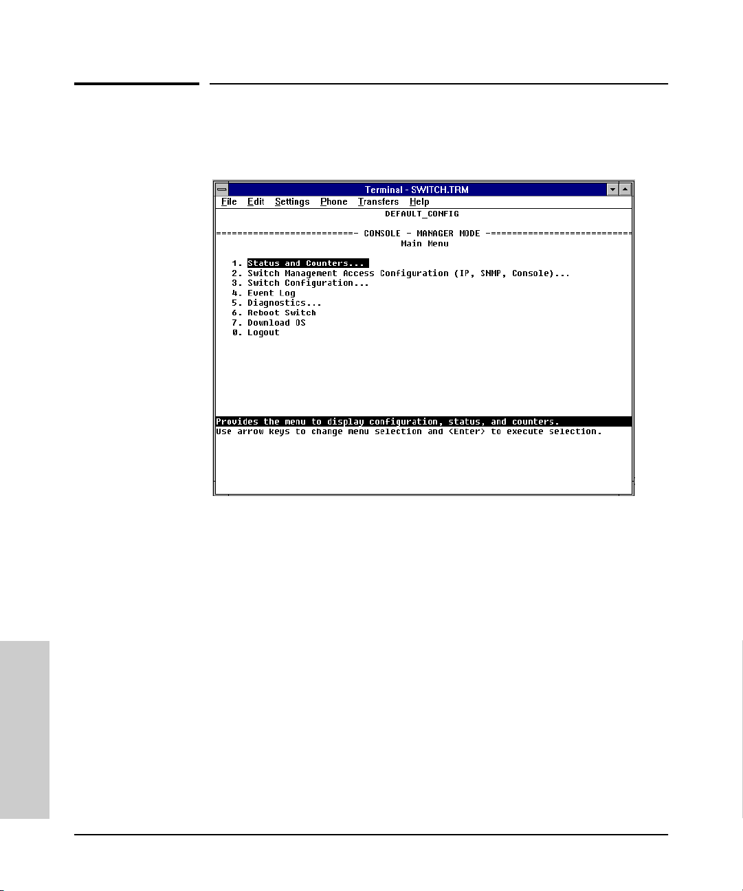
Using the Switch Console Interface
Main Menu Features
Main Menu Features
Figure 4-1. The Main Menu
The Main Menu gives you access to these console interface features:
■ Status and Counters: Provides access to display screens providing
information on switch and port status, network activity, the address
tables, and spanning tree operation. (Refer to chapter 7, “Monitoring and
Analyzing Switch Operation”.)
■ Switch Management Access Configuration: Provides access to
configuration screens that control interaction between the switch and
network management, including IP address, SNMP community names and
trap receivers, console/serial link parameters, and console passwords.
■ Switch Configuration: Provides access to configuration screens that
enable you to display the current configuration settings and to customize
the configuration of the switch features. (Refer to chapter 6, “Configuring
Interface
the Switch”.)
Using the Switch Console
4-4
Page 59

Using the Switch Console Interface
■ Event Log: Enables you to read progress and error messages that are
Main Menu Features
useful for checking and troubleshooting switch operation. (Refer to
“Using the Event Log To Identify Problem Sources” in chapter 8, “Troubleshooting”.)
■ Diagnostics: Provides access to screens for doing Link and Ping connec-
tivity testing, listing the current switch configuration, and to a command
prompt for executing system management, monitoring, and troubleshooting commands. (Refer to “Diagnostics” in chapter 8, “Troubleshooting”.)
■ Reboot Switch: Performs a software reboot of the switch, which clears
most temporary error conditions, resets the network activity counters to
zero, and resets the system up time to zero. A reboot is required (in one
case) to activate a configuration change that has been made. (Refer to
“Rebooting To Activate Configuration Changes” on page 4-13.)
■ Download OS: Enables you to download a new software version to the
switch. (Refer to appendix A, “Transferring an Operating System or
Configuration”.)
■ Logout: Terminates the console session and disconnects Telnet access to
the switch. (Refer to “How to End a Console Session” on page 4-3.)
4-5
Using the Switch Console
Interface
Page 60
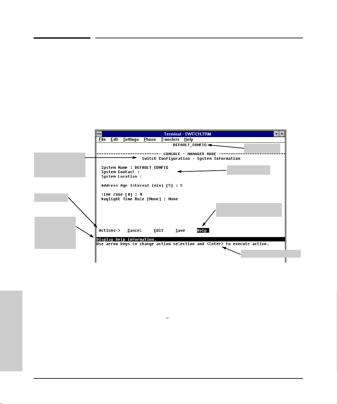
Using the Switch Console Interface
Screen Structure and Navigation
Screen Structure and Navigation
Console screens include these three elements:
■ Parameter fields and/or read-only information such as statistics
■ Navigation and configuration actions, such as Save, Edit, and Cancel
■ Help line to describe navigation options, individual parameters, and read-
only data
For example, in the System Information screen on the next page:
Screen title –
identifies the location
within the menu
structure
Actions line
Help line
describing the
selected action
or selected
parameter field
System name
Parameter fields
Help describing each of the
items in the parameter fields
Navigation instructions
Figure 4-2. Elements of the Screen Structure
“Forms” Design. The configuration screens, in particular, operate similarly
to a number of PC applications that use forms for data entry. When you first
enter these screens, you see the current configuration for the item you have
selected. To change the configuration, the basic operation is to:
1. Press [E] to select the E
dit action.
2. Navigate through the screen making ALL the necessary configuration
changes. (See Table 4-1 on the next page.)
Interface
3. Press [Enter] to return to the Actions line. From there you can save the
configuration changes or cancel the changes. Cancel returns the configu-
Using the Switch Console
ration to the values you saw when you first entered the screen.
4-6
Page 61

Table 4-1. How To Navigate in the Console
Task: Actions:
Using the Switch Console Interface
Screen Structure and Navigation
Execute an action
from the “Actions –>"
list at the bottom of
the screen:
Reconfigure (edit) a
parameter setting or a
field:
Use either of the following methods:
• Use the arrow keys ( [<] ,or [>] ) to highlight the action you want
to execute, then press [Enter].
• Press the key corresponding to the capital letter in the action
name. For example, in a configuration menu, press [E] to select
Edit and begin editing parameter values.
1. Select a configuration item, such as System Name. (See figure
4-2.)
2. Press [E] (for E
3. Use [Tab] or the arrow keys ([<], [>], [^], or [v]) to highlight the
item or field.
4. Do one of the following:
– If the parameter has preconfigured values, either use the
Space bar to select a new option or type the first part of your
selection and the rest of the select ion appears automatically.
(The help line instructs you to “Select” a value.)
– If there are no preconfigured values, type in a value (the Help
line instructs you to “Enter” a value).
5. If you want to change another parameter value, return to step 3.
6. If you are finished editing parameters in the displayed screen,
press [Enter] to return to the Actions line and do one of the
following:
– To save any configuration changes you have made, press [S]
(for the Save action).
– To exit from the screen without saving any changes that you
have made (or if you have not made changes), press [C] (for
the Cancel action).
Note:
Most parameter changes are activated whe n you execute
Save, and it is therefore not necessary to reboot the switch after
making these changes. But if an asterisk appears next to any
menu item you reconfigure, it is necessary to reboot the switch
to implement the change. In this case, rebooting should be done
after you have made all desired changes and then returned to
the Main Menu.
7. When you are finished editing parameters, return to the Main
Menu.
8. If necessary, reboot the switch by highlighting Reboot Switch in
the Main Menu and pressing [Enter]. (Refer to the
dit on the Actions line).
Note
, above.)
Using the Switch Console
Interface
Exit from a read-only
screen.
Press [B] (for the Back action).
4-7
Page 62
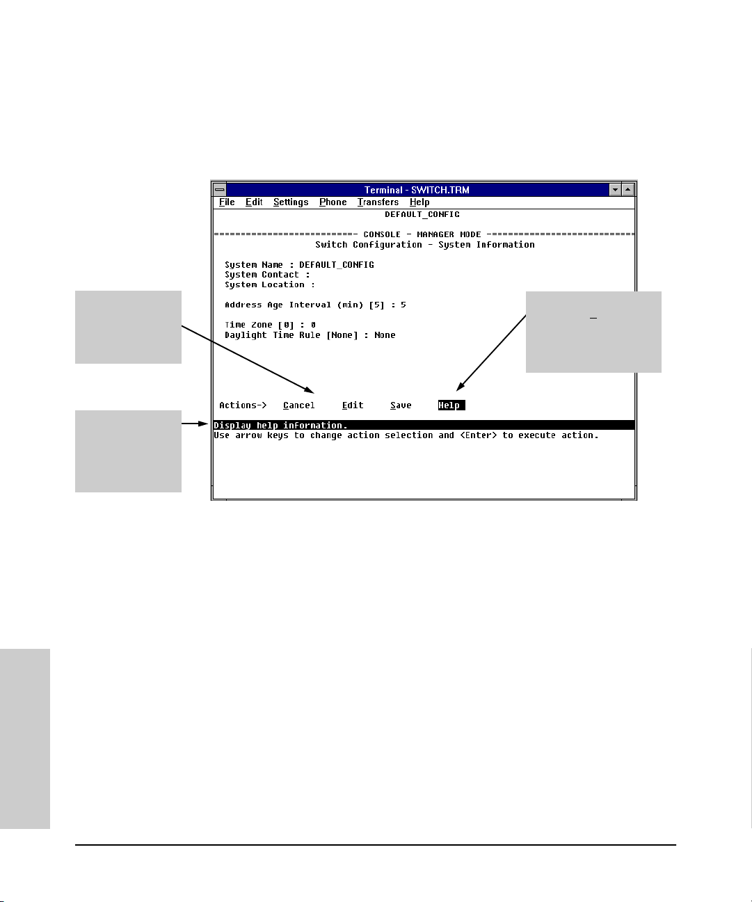
Using the Switch Console Interface
Screen Structure and Navigation
To get Help on individual parameter descriptions. In all screens except
the Command Prompt screen there is a Help option in the Actions line.
Whenever any of the items in the Actions line is highlighted, press [H], and a
separate help screen is displayed. For example:
Highlight on any
item in the Actions
line indicates that
the Actions line is
active.
The Help line
provides a brief
descriptor of the
highlighted Action
item or parameter.
Pressing [H] or
highlighting H
pressing [Enter] displays
Help for the parameters
listed in the upper part of
the screen
elp and
Figure 4-3. Example Showing How To Display Help
To get Help on the actions or data fields in each screen: Use the arrow
keys ( [<], [>], [^], or [v]) to select an action or data field. The help line under
the Actions items describes the currently selected action or data field.
For guidance on how to navigate in a screen: See the instructions provided
at the bottom of the screen, or refer to “Screen Structure and Navigation” on
page 4-6.)
Interface
Using the Switch Console
4-8
Page 63

Using the Switch Console Interface
Using Password Security
Using Password Security
There are two levels of console access: Manager and Operator. For security,
you can set a password on each of these levels.
Level Actions Permitted
Manager: Access to all console interface areas.
This is the default level.
to starting the current console session, then anyone having access to the
console can access any area of the console interface.
That is, if a Manager password has
not
been set prior
Operator: Access to the Status and Counters menu, the Event Log, and the Diagnostics
menu, but no Configuration capabilities.
On the Operator level, the configuration menus, Download OS, and Reboot
Switch options in the Main Menu, and the Command Prompt option in the
Diagnostics menu are not available.
To use password security:
1. Set a Manager password (and an Operator password, if applicable for your
system) as described on page 4-10.
2. Exit from the current console session. A Manager password will now be
needed for full access to the console.
If you do steps 1 and 2, above, then the next time a console session is started,
the console interface will prompt for a password. Assuming that both a
Manager password and an Operator password have been set, the level of
access to the console interface will be determined by which password is
entered in response to the prompt.
If you set a Manager password, you may also want to configure the
Connection Inactivity Time parameter in the Console/Serial Link configuration
screen that is under the Switch Management Access Configuration menu (see
page 6-20). This causes the console session to end after the specified period
of inactivity, thus giving you added security against unauthorized console
access.
Using the Switch Console
Interface
Note The manager and operator passwords control access to both the web browser
interface and the switch console interface.
4-9
Page 64

Using the Switch Console Interface
Using Password Security
Note If there is only a Manager password set (with no Operator password), and the
Manager password is not entered correctly when the console session begins,
the switch operates on the Operator level.
If there are both a Manager password and an Operator password, but neither
is entered correctly, access to the console will be denied.
If a Manager password is not set, anyone having access to the console
interface can operate the console with full manager privileges, regardless of
whether an Operator password is set, by simply pressing [Enter] at the
password prompt.
Passwords are case-sensitive.
The rest of this section covers how to:
■ Set Passwords
■ Delete Passwords
■ Recover from a Lost Password
To set Manager and Operator passwords:
1. From the Main Menu select:
2. Switch Management Access Configuration
5. Console Passwords
Interface
Using the Switch Console
Figure 4-4. The Set Password Screen
4-10
Page 65

Using the Switch Console Interface
Using Password Security
2. To set a new password:
a. Select Set Manager Password or Set Operator Password. You will then
be prompted with Enter new password.
b. Type a password of up to 16 ASCII characters with no spaces and
press [Enter]. (Remember that passwords are case-sensitive.)
c. When prompted with Enter new password again, retype the new pass-
word and press [Enter].
3. When you have finished all password configuration, select Return to Main
Menu to return to the Main menu, or Return to the Previous Menu to return
to the Switch Management Access Configuration menu.
After a password is set, if you subsequently start a new console session, you
will be prompted to enter the password.
To Delete Password Protection (Including Recovery from a Lost
Password): This procedure deletes both passwords (Manager and Opera-
tor). If you have physical access to the switch, press the Clear button on the
front of the switch to clear all password protection, then enter new passwords
as described earlier in this chapter. If you do not have physical access to the
switch, you will need the Manager password:
1. Enter the console at the Manager level.
2. Go to the Console Passwords screen as described above.
3. Select Delete Password Protection. You will then see the following prompt:
Continue Deletion of password protection?
4. Press the Space bar to select Ye s, then press [Enter].
5. Press [Enter] to clear the Password Protection message.
6. Select Return to Main Menu to return to the Main menu, or Return to the
Previous Menu to return to the Switch Management Access Configuration
menu.
To Recover from a Lost Manager Password: If you cannot start a console session at the manager level because of a lost Manager password, you
can clear the password by getting physical access to the switch and pressing
the Clear button. This action deletes all passwords and user names (Manager
and Operator) used by both the console and the web browser interface.
Using the Switch Console
Interface
4-11
Page 66

Using the Switch Console Interface
Rebooting the Switch
Rebooting the Switch
Rebooting the switch terminates the current console session and performs a
reset of the operating system. Rebooting the switch also activates certain
configuration changes that require a reboot and resets statistical counters to
zero. (Note that statistical counters can be reset to zero without rebooting the
switch. See “Displaying Port Counters from the Console Interface” on page
7-12.)
To Reboot the switch, use the Reboot Switch option in the Main Menu. (Note
that the Reboot Switch option is not available if you log on in Operator mode;
that is, if you enter an Operator password instead of a manager password at
the password prompt.)
Reboot Switch option
Figure 4-5. The Reboot Switch Option in the Main Menu
Interface
Using the Switch Console
4-12
Page 67

Using the Switch Console Interface
Rebooting the Switch
Rebooting To Activate Configuration Changes. Configuration changes
for some parameters become effective as soon as you save them. However,
you must reboot the switch in order to implement any changes to any
parameters in the following areas:
■ Console/Serial Link (under 2. Switch Management Access Configuration
menu)
■ VLAN Names (under 3. Switch Configuration | 5. Advanced Feature |
4. VLAN Menu)
If configuration changes requiring a reboot have been made, the switch
displays an asterisk (*) next to the menu item in which the change has been
made. For example, if you change and save parameter values for the switch’s
Console/Serial Link configuration, the need for rebooting the switch would be
indicated by an asterisk appearing next to the item Console/Serial Link in the
Switch Management Access Configuration menu, and in the Main Menu as shown
in figure 4-6:
Asterisk indicates
a configuration
change that
requires a reboot
in order to take
effect.
Reminder to reboot
the switch to activate
configuration
changes.
Using the Switch Console
Interface
Figure 4-6. Example of a Configuration Change Requiring a Reboot
4-13
Page 68

Using the Switch Console Interface
The Command Prompt
The Command Prompt
In addition to the menu-based part of the console interface, under the Diagnostics Menu, a command-line based interface is available. The commands are
primarily for the expert user and for diagnostics purposes, although there are
commands for setting some basic items on the switch such as the date and
time. Additionally, the Set command can be used to configure a number of
switch parameters and the Show command can be used to display switch
status and network counters information.
How To Use the Command Prompt:
1. From the Main Menu, select 5. Diagnostics ... , then from the Diagnostics
Menu, select 4. Command Prompt
2. One of the following appears:
• If VLANs are configured, you will see a prompt similar to the following:
• If no VLANs are configured, the command prompt appears near the
Select VLAN : DEFAULT_VLAN
Use the Space bar to select the VLAN in which you want to execute a
command, then press [Enter] to display the command prompt. The text
in the prompt will match the name of the VLAN you select.
bottom of the screen. For example:
DEFAULT_CONFIG:
The text in the prompt matches the System Name parameter. In the
above example, the factory default configuration name appears
because no system name is configured.
3. Type in the command you want to execute and press [Enter]. For example,
to set the time to 9:55 a.m. you would execute the following command:
DEFAULT_CONFIG: time 9:55 [Enter]
How To Exit from the command prompt:
Typ e exit and press [Enter] to return to the Diagnostics Menu.
Interface
Using the Switch Console
4-14
Page 69

Using the Switch Console Interface
The Command Prompt
Commands Available
The following commands are available from the command prompt (this
information can also be displayed by entering help or he at the command
prompt. When you see -- MORE -- at the bottom of the screen:
■ To advance the display one line at a time, use [Enter].
■ To advance the display one screen at a time, use the Space bar.
■ To stop the help listing, press [Q]:
Table 4-1. List of Commands Available at the Command Prompt
Command Description
Help Help [All]; Shows help information about commands.
Exit Returns to the Diagnostics Menu.
Browse Displays the switch configuration in readable form.
Config Displays the switch configuration file stored in flash.
Date Displays or sets the date and time; to set: date mm/dd/yy.
Time Displays or sets the date and time; to set: time hh:mm:ss
Set Configures some switch parameters. Use ’set help’ for more
information.
Show Displays some switch settings. Use ’show help’ for more
information.
Delete delete CONFIG; Deletes the configuration file stored in flash.
History Displays the switch shutdown history.
Kill Kills all other active telnet/console sessions.
Get get <ip-addr> CONFIG <remote-file>; Copies the configuration file
<remote-file> from the host identified by <ip-addr>
Put put <ip-addr> <file> <remote-file> [UNIX | PC]; Copies the item
specified by ILOH! to the host identified by LSDGGU!. <file> is
CONFIG or any command; <remote-file> is the destination file name
on the host; UNIX formats a text file with line feeds (default).
LinkTest linktest <MAC-addr>; Sends an 802.2 Test packet to the device
identified by <MAC-addr>.
Log log [-a | keyword | -a keyword]; Displays the current switch log: -a
displays the entire internal event log; keyword displays only the
events that contain the keyword.
Page Toggles paging mode on and off for display commands.
Using the Switch Console
Interface
4-15
Page 70

Using the Switch Console Interface
The Command Prompt
Command Description
Ping ping <ip-addr> [count] [wait]; Sends IP ’Echo Request’ packets to the
Print print <cmd>; Sends the output from the command <cmd> to a
Redo redo [? | <number> | <string>]; Displays command history or executes
GetMIB getmib <obj-id>; Shows the value of the managed object <obj-id>.
SetMIB setmib <obj-id > <type> <value>; Sets the value of the managed object
Xget xget CONFIG; Retrieves the configuration file using XModem.
Xput xput <file> [PC | UNIX]; Sends the item identified by <file> using
romversion Displays the switch ROM version.
device identified by <ip-addr>. count sets the number of packets,
wait sets the time to wait for a response in seconds.
printer or file.
a command from the history:
redo -- re-executes the most recent command.
redo ? -- displays the command history.
redo <number> -- re-executes a previous command indexed by
<number>
redo <string> -- re-executes a previous command that begins with
the text <string>.
<obj-id> of the type <type> with the value <value>.
XModem. <file> is CONFIG, CRASHREC, LOGFILE, or any command.
PC formats the file with carriage returns and line feeds; UNIX
formats the file with line feeds only.
Version Displays the switch OS version.
Vlan vlan <vlan-name>; Changes the VLAN in which the commands are
executed.
WalkMIB walkmib <obj-id>; Displays a group of managed object values.
Interface
Using the Switch Console
4-16
Page 71

Using the Switch Console Interface
The Command Prompt
Set and Show Commands
Most of the commands at the command prompt are useful for diagnostics
purposes, but the set commands can be used to configure some of the switch’s
basic features, and the show commands can be used to display switch and port
status and activity information. These commands can be run from UNIX
scripts so they can be executed on an automatic, timed basis.
To get help on the set and show commands, type help at the end of the
command line; for example show help to display help for the show command,
or set spantree hello help to display help on how to configure the Spanning Tree
Hello Time parameter.
Set Commands
Table 4-2. Set Commands Available at the Command Prompt
Command Description
set abc set abc <enable | disable>; Enables or disables the Automatic
Broadcast Control (ABC) feature. This feature is disabled by
default. For more information on ABC, see page 6-106.
set igmp set igmp <enable | disable>; Enables or disables the IP Group
Management Protocol (IGMP) feature for IP multicast traffic
control. This feature is disabled by default. For more information
on IGMP, see page 6-95.
set port set port <enable | disable> <port-number>; Enables or disables the
switch port specified by <port-number>. All the switch ports are
enabled by default.
set spantree set spantree <parameter>; Configures the Spanning Tree Protocol
(STP) parameters, where <parameter> can be:
• enable -- enables STP operation on the switch, using the default
values for the STP parameters (STP is disabled by default).
• disable -- disables STP operation.
• fwddelay <delay> -- sets the STP forward delay value (default =
15, range = 4 - 30 seconds).
• hello <interval> -- sets the STP hello time interval (default = 2,
range = 1 - 10).
• maxage <agingtime> -- sets the STP max aging interval (default =
20, range = 6 - 40).
• portcost <port-number> <cost> -- sets the STP port cost for the
specified switch port (default = dependent on port speed, range
= 1 - 65535).
• portpri <port-number> <priority> -- sets the STP port priority for the
specified port (default = 128, range = 0 - 255).
For more information on Spanning Tree, see page 6-39.
Using the Switch Console
Interface
4-17
Page 72

Using the Switch Console Interface
The Command Prompt
Command Description
set system set system <parameter>; Configures the switch identification
parameters, where <parameter> can be:
• contact <contact-name> -- sets a user-defined name for someone
to contact for switch administration.
• location <location> -- sets a user-defined switch location
description.
• name <switch-nam e> -- sets a user-defined identification name for
the switch.
Show Commands
Table 4-3. Show Commands Available at the Command Prompt
Command Description
show bridge show bridge [port-number]; Displays the switch address table, or
show filters show filters; Displays the traffic/security filters that have been
show ip show ip; Displays the switch IP address configuration. If multiple
show module show module; Displays status information for any modules installed
optionally for the specified port.
configured on the switch.
VLANs are configured, the IP address configuration for all VLANs
is displayed.
in the switch.
show port show port <parameter>; Displays status information for the switch
ports, where <parameter> can be:
• counters [port-number] -- displays network traffic counters for all
the switch ports, or optionally, for the specified port.
• status [port-number] -- displays the status of all the switch ports,
or optionally, for the specified port.
• spantree -- displays a summary of the spanning tree configuration
and status of all the switch ports.
show snmp show snmp; Displays the switch SNMP communities configuration.
show
spantree
show system show system; Displays a summary of the switch system
Interface
show spantree; Displays a summary of the switch-level Spanning
Tree configuration and status.
configuration and switch memory and buffer usage.
Using the Switch Console
4-18
Page 73

Using HP TopTools or Other SNMP Tools To
Monitor and Manage the Switch
You can manage the switch via SNMP from a network management station.
Included with your switch is a CD-ROM containing a copy of HP TopTools for
Hubs & Switches, an easy-to-install and use network management application
that runs on your Windows NT- or Windows 95-based PC.
HP TopTools for Hubs & Switches provides control of your switch through its
graphical interface. In addition, it makes use of the RMON agent and statistical
sampling software that is included in the switch to provide powerful, but easyto-use traffic monitoring and network activity analysis tools.
This chapter provides:
■ An overview of SNMP management for the switch
■ An overview of the configuration process for supporting SNMP manage-
ment of the switch. (For the configuration procedures for specific fea-
tures, refer to chapter 6, “Configuring the Switch”.)
■ Information on advanced management through RMON and HP Extended
RMON Support
5
Monitoring and Managing
the Switch
To implement SNMP management, you must either configure the switch with
the appropriate IP address or, if you are using DHCP/Bootp to configure the
switch, ensure that the DHCP or Bootp process provides the IP address. (The
IPX address is automatically learned.) If multiple VLANs are configured, each
VLAN interface should have its own IP or IPX network address.
SNMP Management Features
SNMP management features on the switch include:
■ Security via configuration of SNMP communities
■ Event reporting via SNMP traps and RMON
■ Managing the switch with a network management tool such as HP Top-
Tools for Hubs & Switches
5-1
Page 74

Monitoring and Managing
Using HP TopTools or Other SNMP Tools To Monitor and Manage the Switch
SNMP Management Features
■ Monitoring data normally associated with the SNMP agent (“Get”
operations). Supported Standard MIBs include:
• Bridge MIB (RFC 1493)
dot1dBase, dot1dTp, dot1dStp
• Ethernet MAU MIB (RFC 1515)
dot3IfMauBasicGroup
the Switch
• Interfaces Evolution MIB (RFC 1573)
ifGeneralGroup, ifRcvAddressGroup, ifStackGroup
• RMON MIB (RFC 1757)
etherstats, events, alarms, and history
• SNMP MIB-II (RFC 1213)
system, interfaces, at, ip, icmp, tcp, udp, snmp
• Entity MIB (RFC 2037)
HP Proprietary MIBs include:
• Statistics for message and packet buffers, tcp, telnet, and timep
(netswtst.mib)
• Port counters, forwarding table, and CPU statistics (stat.mib)
• tftp download (downld.mib)
• Integrated Communications Facility Authentication Manager and
SNMP communities (icf.mib)
• HP ProCurve Switch configuration (config.mib)
• HP VLAN configuration information (vlan.mib) supporting
hpVlanGeneralGroup
• HP Extended RMON MIB version 4 to allow statistical sampling
• HP Entity MIB (entity.mib)
5-2
The switch SNMP agent also uses certain variables that are included in a
Hewlett-Packard proprietary MIB file you can add to the SNMP database
in your network management tool. You can copy the MIB file from the HP
TopTools for Hubs & Switches CD shipped with the switch, or from
following World Wide Web site:
http://www.hp.com/go/procurve
For more information, refer to Customer Support/Warranty booklet
included with your switch.
Page 75

Using HP TopTools or Other SNMP Tools To Monitor and Manage the Switch
SNMP Configuration Process
SNMP Configuration Process
This requires that you configure the switch with the appropriate IP address.
(Refer to chapter 2, “Configure an IP Address on the Switch”. If you are using
DHCP/Bootp to configure the switch, ensure that the DHCP/Bootp process
provides the IP address. (Refer to “DHCP/Bootp Operation” on page 6-9.)
The general steps to configuring for SNMP access to the preceding features
are:
1. From the Main menu, select
2. Switch Management Access Configuration
1. IP Configuration
2. Use either of the following methods to configure a network address for
the switch, including any necessary gateway:
• Use DHCP/Boot, which is enabled by default, to acquire an IP address.
Make sure the DHCP/Bootp server is configured to support the
switch. (Refer to “DHCP/Bootp Operation” on page 6-9.)
• Manually configure an IP address. (Refer to chapter 2, “Configuring
an IP Address on the Switch”.)
3. Configure the appropriate SNMP communities. (The “public” community
exists by default and is used by HP’s network management applications.)
(For more on configuring SNMP communities, refer to “SNMP Communities” on page 6-14.)
Monitoring and Managing
the Switch
4. Configure the appropriate trap receivers. (For more on configuring trap
receivers, refer to “Trap Receivers” on page 6-17.)
In many networks, manager addresses are not used. In this case, all management stations using the correct community name may access this device with
the View and Access levels that have been set for that community. If you want
to restrict access to one or more specific nodes, you can enter up to ten IP
addresses of such nodes into the Manager Address field. Configuring one or
more IP addresses in the Manager Address field means that only the network
management stations at those addresses are authorized to use the community name to access the switch.
5-3
Page 76

Monitoring and Managing
Using HP TopTools or Other SNMP Tools To Monitor and Manage the Switch
Advanced Management: RMON and HP Extended RMON Support
Caution Deleting the community named “public” disables many network management
functions (such as auto-discovery, traffic monitoring, and threshold setting).
If security for network management is a concern, it is recommended that you
change the write access for the “public” community to “Restricted”.
the Switch
Note SNMP community and trap receiver configurations are activated when saved.
Rebooting the switch is not necessary unless you have also configured other
parameters that require rebooting in order to be activated. (For more on when
it is necessary to reboot, refer to “Rebooting the Switch” on page 4-12.)
Advanced Management: RMON and HP
Extended RMON Support
The switch supports RMON (Remote Monitoring) and HP Extended RMON
on all connected network segments. This allows for troubleshooting and
optimizing your network.
5-4
RMON
The following RMON groups are supported:
■ Ethernet Statistics (except the numbers of packets of different frame sizes)
■ Alarm
■ History (of the supported Ethernet statistics)
■ Event
You can access the Ethernet statistics, Alarm, and Event groups from the HP
TopTools for Hubs & Switches network management software included with
your switch.
Extended RMON
Extended RMON provides network monitoring and troubleshooting information that analyzes traffic from a network-wide perspective. Extended RMON
notifies you about network problems and identifies the end node at fault. That
information can be used to set up RMON to study the problem more closely,
if desired. Because it is based on detailed statistical sampling, Extended
RMON lessens the load on devices and network bandwidth.
Page 77

Configuring the Switch
Overview
This chapter describes the switch configuration features available in both the
switch console and the HP web browser interface. If you need information
on how to operate either the web browser interface or the console, refer to:
■ Chapter 3, “Using the HP Web Browser Interface”
■ Chapter 4, “Using the Switch Console Interface”
Why Reconfigure? In its factory default configuration, the switch operates
as a multiport learning bridge with network connectivity provided by the ports
on the switch and/or on the particular modules you have installed. However,
to enable specific management features and to “fine-tune” your switch for the
specific performance and security needs in your network, you may want to
reconfigure individual switch parameters.
6
Configuring the Switch
How To Find Configuration Information. Each section in this chapter is
organized as follows:
■ Introductory feature information: Provides an overview of the fea-
ture.
■ “How-To” Configuration steps: Describes the step-by-step process
used to actually configure the feature. It also includes examples of the
web browser interface and console interface screens.
■ Detailed feature information: Provides a more in-depth description of
the feature, along with notes on interoperation with other features.
To find a specific feature, see the table in the next section.
6-1
Page 78

Configuring the Switch
Overview
Configuration Features
Table 6-1. Configurable Feature Comparison
Feature Switch
Authentication Traps/
Trap Receivers
Authorized IP Managers Yes Yes 6-21
Automatic Broadcast Control (ABC) Yes Yes 6-106
Class of Service (CoS) Yes Yes 6-130
Console/Serial Link
• Enable Inbound Telnet to Console
• Enable Web Browser Interface Access
• Terminal Settings
Fault Detection Yes Yes 3-27
IP Configuration Yes Yes 6-4
Configuring the Switch
IP Multicast (IGMP) Enable/Disable
IGMP Priority and Port Settings
Load Balancing: Port Trunking
Load Balancing: Switch Meshing
Network Monitoring Port Yes Yes 6-34
Operator and Manager Usernames
Operator and Manager Passwords
Port Settings Yes Yes 6-30
Console
Yes —6-17
Ye s
Ye s
Ye s
Ye s
Ye s
Ye s
Ye s
—
Ye s
Web
Browser
—
—
—
Ye s
—
—
—
Ye s
Ye s
Page
6-19
6-20
6-20
6-20
6-95
6-70
6-80
3-8
3-8, 4-9
6-2
Port Security Yes Yes 6-118
Port-Based Virtual LANs (VLANs) Yes — 6-51
SNMP Communities Yes — 6-14
Spanning Tree Enable/Disable
Spanning Tree Parameters
System Information
Address Age Interval
System Time
Time Protocol Yes — 6-7
Traffic/Security Filters Yes — 6-46
Ye s
Ye s
Ye s
Ye s
Ye s
Ye s
—
Ye s
—
—
6-39
6-28
Page 79

Configuring the Switch
Overview
Note In the factory default configuration, the Spanning Tree Protocol (STP—which
automatically blocks redundant links) is disabled. Generally, you should
enable STP to prevent broadcast storms if there are redundant links in your
network that are not part of a switch mesh. However, due to the requirements
of the 802.1Q VLAN standard, STP blocks unmeshed redundant physical links
even if they are in separate VLANs. This could result in blocking links unnecessarily. Switch meshing can allow use of STP without the problem of blocking
links that could remain open. For more information, refer to “Load Balancing:
Switch Meshing” on page 6-80, and “Spanning Tree Protocol” on page 6-39.
Configuring the Switch
6-3
Page 80

Configuring the Switch
IP Configuration
IP Configuration
Configuring the switch with an IP address expands your ability to manage the
switch, and also enhances the switch features that can be used.
The switch console screen enables you to configure the initial values for:
■ IP address, subnet mask, and (optionally) the gateway address for the
switch so that it can be managed in an IP network
■ The time server information (used if you want the switch to get its time
information from another device operating as a Timep server)
The web browser interface screen enables you to modify the initial IP
configuration if needed.
Note If you change the IP address through the web browser interface, the browser
will lose connection to the switch. You can reconnect by entering the new IP
Configuring the Switch
address as the URL.
By default, the switch is configured to receive IP addressing from a DHCP/
Bootp server that you have configured correctly with information for your
switch. (Refer “DHCP/Bootp Operation” on page 6-9 for information on setting
up automatic configuration from a server.) Through the web browser interface
or switch console, you can manually enter a different address, or you can
disable the IP operation.
Notes ■ If VLANs are not configured, then configure one IP address for the entire
switch. If VLANs are configured, then configure an IP address for each
VLAN. This is because each VLAN is a separate network and requires a
unique IP address, and subnet mask. A gateway (IP) address is optional.
For more on VLANs, refer to “Virtual LANs (VLANs)” on page 6-51.
■ The IP addressing used in the switch should be compatible with your
network: the IP address must be unique, and the subnet mask must be the
same for all devices on the same IP network.
■ If you plan to connect to other networks that use globally administered
IP addressing, refer to “Globally Assigned IP Network Addresses” on page
6-13.
For information on how IP addressing affects switch performance, refer to
“How IP Addressing Affects Switch Operation” on page 6-8.
6-4
Page 81

Configuring the Switch
IP Configuration
Configuring IP Addressing from the Web Browser Interface
1. Click here.
2. Click here.
3. If multiple VLANs
are configured,
select a VLAN.
4.To enable manual entry
of the IP address, set this
to “Manual”.
5. Enter an IP address, subnet
mask, and, if needed, the IP
address of t he default gateway.
6.Click on this to activate
the changes you made in
steps 3 - 5.
Figure 6-7. Configuring IP Addressing on the Web Browser Interface
Configuring the Switch
Parameter Description
VLAN If you have configured multiple VLANs, then use this parameter to
select the VLAN to which you want to assign an IP address. Otherwise,
leave it set to the default.
IP Configuration The method the switch uses to acquire its IP configuration.
• DHCP/Bootp (default): The switch attempts to get its IP
configuration or its complete configuration from a DHCP or Bootp
server.
• Manual: Enables you to manually enter the IP configuration into the
next three fields.
• Disabled: Network management access to the switch over IP is
disabled.
6-5
Page 82

Configuring the Switch
IP Configuration
Parameter Description
IP Address IP address for the switch (or VLAN) IP interface. If DHCP/Bootp is
Subnet Mask The same subnet mask that is used by all devices in the IP subnet being
Default Gateway The IP address of the next-hop gateway node for reaching off-subnet
selected for IP Configuration, this is a read-only field displaying the
value received from a DHCP or Bootp server.
configured. If DHCP/Bootp is selected for IP Configuration, this is a
read-only field displaying the value received from a DHCP or Bootp
server.
destinations. Used as the default gateway if the requested destination
address is not on the local subnet. If DHCP/Bootp is selected for IP
Configuration, this is a read-only field displaying the value received
from a DHCP or Bootp server.
Configuring IP Addressing from the Switch Console
You can use the console to manually configure an IP address, subnet mask,
and a Gateway IP address (if needed). Or, you can use DHCP/Bootp to
configure IP from a DHCP or Bootp server. (To use the DHCP/Bootp option,
Configuring the Switch
you must also configure the DHCP or Bootp server accordingly.)
Do one of the following:
■ To use the console, set the IP Config parameter to Manual and then
manually enter the IP address, subnet mask, and default gateway you want
for the switch.
■ If you plan to use DHCP or Bootp, use the console to ensure that the IP
Config parameter is set to DHCP/Bootp, then refer to “DHCP/Bootp Opera-
tion” on page 6-9.
To Access IP Addressing:
1. From the Console Main Menu, Select...
2. Switch Management Access Configuration (IP, SNMP, Console)...
1. IP Configuration
Note If multiple VLANs are configured, a screen showing all VLANs appears instead
of the following screen. You would first select the VLAN you want to configure,
then the following screen would appear to configure IP for that VLAN.
6-6
Page 83

The default setting for
Time Protocol Config is
DHCP. Setting it to
Manual, then pressing [v]
or [Tab] causes the Timep
Server Address
parameter to appear.
The default setting for IP
Config is DHCP/Bootp.
Using the Space bar to set
it to Manual, then
pressing [v] or [Tab] causes
the IP Address, Subnet
Mask, and Gateway
parameters to appear.
For descriptions of these
parameters, refer to the
online Help for this screen.
Before using the DHCP/
Bootp option, refer to
DHCP/Bootp Operatio n on
page 6-9.
Configuring the Switch
IP Configuration
Configuring the Switch
Figure 6-8. Example of the IP Service Configuration Screen
2. Press [E] (for E
dit).
3. At the Time Protocol Conf ig field, if you want the switch to obtain its system
time from a Timep server, and the server is configured correctly, keep the
value as DHCP , or use the Space bar to select Manual. If you don’t have
a Timep server set up, use the Space bar to change to value to Disable.
4. If you select Manual , press the Tab or Down Arrow key, and additional
fields will be displayed for entering the IP address and subnet mask for
the Timep server.
5. Select the Time Poll Interval field if you want to change to value for how
often the switch will poll the Timep server for time information.
6. If you want to have the switch retrieve its IP configuration from a DHCP
or Bootp server, at the IP Config field, keep the value as DHCP/Bootp and
go to step 10. If you want to manually configure the IP information, use
the Space bar to select Manual and press the Tab or Down Arrow key to
reveal the other IP configuration fields.
7. Select the IP Address field and enter the IP address for the switch.
8. Select the Subnet Mask field and enter the subnet mask for the IP address.
6-7
Page 84

Configuring the Switch
IP Configuration
9. If you want to reach off-subnet destinations, select the Gateway field and
enter the IP address of the gateway router.
10. Press [Enter], then [S] (for S
ave).
11. Return to the Main Menu.
How IP Addressing Affects Switch Operation
Without an IP address and subnet mask compatible with your network, the
switch operates as a multiport transparent bridge and can be managed only
through a direct terminal device connection to the Console RS-232 port. In
this state, the switch simply learns which nodes are on which ports and
forwards or blocks traffic accordingly. You can use direct-connect console
access to take advantage of features that do not depend on IP addressing.
However, to realize the full performance capabilities HP proactive networking
offers through the switch, configure the switch with an IP address and subnet
mask compatible with your network. The following table lists the general
features available with and without a network-compatible IP address configured.
Configuring the Switch
Features Available Without an IP Address Additional HP Proactive Networking Features Available
• Direct-connect console access
• DHCP or Bootp support for automatic IP address
configuration, and DHCP support for automatic time
server IP address configuration
• Spanning Tree Protocol
• Port trunking
• Traffic filtering
• Console-based status and counters information for
monitoring swit ch operation and diagnos ing problems.
•VLANs
• Serial downloads of operating system (OS) updates
and configuration files (Xmodem)
with an IP Address and Subnet Mask
• HP web browser interface access, with configuration,
security, and diagnostic tools, plus the Alert Log for
discovering problems detected in the switch along
with suggested solutions
• SNMP network management access such as HP
TopTools network configuration, monitoring, problemfinding and reporting, analysis, and recommendations
for changes to increase control and uptime
• Telnet console access
• Automatic Broadcast Control (ABC)
•IGMP
• Time server configuration
• TFTP download of configurations and OS updates
•Ping test
6-8
Page 85

Configuring the Switch
IP Configuration
DHCP/Bootp Operation
Overview
DHCP/Bootp is used to download configuration data from a DHCP or Bootp
server respectively to the switch or to a VLAN configured on the switch. With
DHCP you can have the switch automatically retrieve the IP address with no
configuration required on either the switch or the DHCP server. A Bootp server
requires some configuration, but you can additionally identify a file to be
downloaded to the switch containing a full switch configuration.
Note The Switches 1600M/2424M/4000M/8000M are compatible with both DHCP
and Bootp servers.
To use DHCP/Bootp for IP configuration of a VLAN, the DHCP/Bootp server
must be in that VLAN in order for the switch to access it.
The DHCP/Bootp Process
Whenever the IP Config parameter in the switch or in an individual VLAN in
the switch is configured to DHCP/Bootp (the default), or when the switch is
rebooted with this configuration:
1. DHCP/Bootp requests are automatically broadcast on the local network.
(The switch sends one type of request which either a DHCP or Bootp
server can process.)
2. When a DHCP or Bootp server receives the request, it replies with an
automatically generated IP address and subnet mask for the switch. The
switch also receives an IP Gateway address if the server has been configured to provide one. In the case of Bootp, the server must first be
configured with an entry that has the MAC address of the switch. (The
switch properly handles replies from either type of server. If multiple
replies are returned, the switch tries to use the first DHCP reply.)
If the switch is initially configured for DHCP/Bootp operation (the default),
or if it is rebooted with this configuration, it immediately begins sending
request packets on the network. If the switch does not receive a reply to its
DHCP/Bootp requests, it continues to periodically send request packets, but
with decreasing frequency. Thus, if a DHCP or Bootp server is not available
or accessible to the switch when DHCP/Bootp is first configured, the switch
may not immediately receive the desired configuration. After verifying that
the server has become accessible to the switch, reboot the switch to re-start
the process.
Configuring the Switch
6-9
Page 86

Configuring the Switch
IP Configuration
DHCP Operation. A significant difference between a DHCP configuration
and a Bootp configuration is that an IP address assignment from a DHCP
server is automatic, requiring no configuration of the DHCP server. Using that
automatic feature, though, the address is temporarily leased. Periodically the
switch may be required to renew its lease of the IP configuration. Thus, the IP
addressing provided by the server may be different each time the switch
reboots or renews its configuration from the server. However, you can fix the
address assignment for the switch by doing either of the following:
■ Configure the server to issue an “infinite” lease.
■ Using the switch’s MAC address as an identifier, configure the server with
a “Reservation” so that it will always assign the same IP address to the
switch. (For MAC address information, refer to appendix B, “MAC
Address Management”.)
For more information on either of these procedures, refer to the documentation provided with the DHCP server.
Bootp Operation. When a Bootp server receives a request it searches its
Bootp database for a record entry that matches the MAC address in the Bootp
request from the switch. If a match is found, the configuration data in the
Configuring the Switch
associated database record is returned to the switch. For most Unix systems,
the Bootp database is contained in the /etc/bootptab file. In contrast to DHCP
operation, Bootp configurations are always the same for each receiving
device. That is, the Bootp server replies to a request with a configuration
previously stored in the server and designated for the requesting device.
6-10
Bootp Database Record Entries. A minimal entry in the Bootp table file
/etc/bootptab to update an IP address and subnet mask to the switch or a VLAN
configured in the switch would be similar to this entry:
j4121switch:\
ht=ether:\
ha=040009123456:\
ip=55.66.77.88:\
sm=255.255.248.0:\
gw=55.66.77.1:\
lg=11.22.33.44:\
hn:\
vm=rfc1048
Page 87

Configuring the Switch
IP Configuration
An entry in the Bootp table file /etc/bootptab to tell the switch or VLAN where
to obtain a configuration file download would be similar to this entry:
j4121switch:\
ht=ether:\
ha=040009123456:\
ip=55.66.77.88:\
sm=255.255.248.0:\
gw=55.66.77.1:\
lg=11.22.33.44:\
T144=”switch.cfg”:\
vm=rfc1048
where:
j4121switch is a user-defined symbolic name to help you find the correct section of the
ht is the “hardware type”. For the Switches 1600M/2424M/4000M/8000M, set this
ha is the “hardware address” . Use the switch's (or VLAN's) 12 -digit MAC address.
ip is the IP address to be assigned to the switch (or VLAN).
sm is the subnet mask of the subnet in which the switch (or VLAN) is installed.
gw is the IP address of the default gateway.
lg TFTP server address (source of final configuration file)
T144 is the vendor-specific “tag” identifying the configuration file to download.
vm is a required entry that specifies the Bootp report format. For the Switches
bootptab file. If you have multiple switches that will be using Bootp to get their
IP configuration, you should use a unique symbolic name for each switch.
to ether (for Ethernet).
1600M/2424M/4000M/8000M, set this parameter to rfc1048.
This tag must precede the
ha
tag
.
Note The above Bootp table entry is a sample that will work for the Switches 1600M/
2424M/4000M/8000M when the appropriate addresses and file names are used.
There are other features and parameters that can be implemented with Bootp.
See the documentation for your Bootp server for more information.
Configuring the Switch
6-11
Page 88

Configuring the Switch
IP Configuration
Configuring DHCP/Bootp
In its default configuration, the switch is configured for DHCP/Bootp operation. However, if an IP address has previously been configured or if the IP
Config parameter has been set to Disabled, then you will need to use this
procedure to reconfigure the parameter to enable DHCP/Bootp operation.
This procedure assumes that, for Bootp operation:
■ A Bootp database record has already been entered into an appropriate
Bootp server.
■ The necessary network connections are in place
■ The Bootp server is accessible from the switch
and, for DHCP operation:
■ The necessary network connections are in place
■ A DHCP server is accessible from the switch
To configure the switch or a VLAN for DHCP/Bootp:
1. From the Main Menu, select
Configuring the Switch
2. Switch Management Access Configuration (IP, SNMP, Console)
1. IP Configuration
6-12
2. Press [E] (for Edit mode), then use [v] to move the cursor to the
IP Config parameter field.
3. Use the Space bar to select the DHCP/Bootp option for the IP Config
parameter. (This disables access to the IP Address, Subnet Mask, and
Gateway parameters.)
4. Press [Enter] to exit from edit mode, then press [S] to save the configuration
change.
When you press [S] to save the configuration change or reboot the switch with
DHCP/Bootp enabled in a network providing DHCP/Bootp service, it will do
the following:
■ Receive an IP address and subnet mask and, if configured in the server, a
gateway IP address and the address of a Timep server.
■ For Bootp operation, if the reply provides information for downloading a
configuration file, the switch then uses TFTP to download the file from
the designated source, then reboots itself. (This assumes that the switch
or VLAN has connectivity to the TFTP file server specified in the Bootp
database configuration record, that the Bootp database record is correctly
configured, and that the configuration file exists in the TFTP directory.)
Page 89

Configuring the Switch
IP Configuration
Globally Assigned IP Network Addresses
If you intend to connect your network to other networks that use globally
administered IP addresses, Hewlett-Packard strongly recommends that you
use IP addresses that have a network address assigned to you. There is a
formal process for assigning unique IP addresses to networks worldwide.
Contact one of the following companies:
Country Phone Number/E-Mail/URL Company Name/Address
United States/
Countries not in
Europe or Asia/Pacific
Europe +31 20 592 5065
Asia/Pacific domreg@apnic.net
1-703-742-4777
questions@internic.net
http://rs.internic.net
ncc@ripe.net
http://www.ripe.net
http://www.apnic.net
Network Solutions, Inc.
Attn: InterNIC Registration Service
505 Huntmar Park Drive
Herndon, VA 22070
RIPE NCC Kruislaan
409NL-1098 SJ
Amsterdam, The Netherlands
Attention: IN-ADDR.ARPA Registration
Asia Pacific Network Information Center
c/o Internet Initiative Japan, Inc.
Sanbancho Annex Bldg. 1-4 Sanban-cho
Chiyoda-ku Tokyo 102, Japan
For more information, refer to Internetworking with TCP/IP: Principles,
Protocols and Architecture by Douglas E. Comer (Prentice-Hall, Inc.,
publisher).
Configuring the Switch
6-13
Page 90

Configuring the Switch
SNMP Communities
SNMP Communities
From the switch console only you can add, edit, or delete SNMP communities. Use this feature to restrict access to the switch by SNMP management
stations. You can configure up to five SNMP communities, each with either an
operator-level or a manager-level view, and either restricted or unrestricted
write access.
In the default configuration, no Manager addresses are configured, and all
management stations using the correct community name may access the
switch with the corresponding View and Access levels specified for those
communities. For any community name, if you want to restrict access to one
or more specific nodes, you can enter up to ten IP addresses of such nodes
into the Manager Address field. Entering one or more IP addresses in the
Manager Address field restricts access with that community to only those
addresses.
Configuring the Switch
For more on this topic, refer to chapter 5, “Using HP TopTools or Other SNMP
Tools To Monitor and Manage Your Network”, and to the online Help.
Configuring SNMP Communities from the Switch Console
Before you begin, ensure that the switch has been configured for IP.
Caution Deleting or changing the community named “public” prevents network man-
agement applications (such as auto-discovery, traffic monitoring, and threshold setting) from operating in the switch. (Changing or deleting the “public”
name also generates an Event Log message.) If security for network management is a concern, it is recommended that you change the write access for the
“public” community to “Restricted”.
6-14
Page 91

To View, Edit, or Add SNMP Communities:
1. From the Console Main Menu, Select:
2. Switch Management Access Configuration (IP, SNMP, Console)...
2. SNMP Community Names/Authorized Managers
Add and Edit options are used to mo dify
the SNMP options. See figure 6-6-10.
Configuring the Switch
SNMP Communities
Configuring the Switch
Note: This screen gives an overview of the SNMP communities that
are currently configured. All fields in this screen are read-only.
Figure 6-9. The SNMP Communities Screen (Default Values)
2. From the Configuration screen, select SNMP Communities to display a
screen similar to the one above.
3. Press [A] (for Add) to display the following screen:
6-15
Page 92

Configuring the Switch
SNMP Communities
If you are adding a
community, the fields in
this screen are blank.
If you are editing an
existing community, the
values for the currently
selected Community
appear in the fields.
Type the value for
these fields.
Use the Space bar
to select values for
other fields
Configuring the Switch
Figure 6-10. The SNMP Add or Edit Screen
Note In the default configuration, no manager addresses are configured. In this
case, all management stations using the correct community name may access
the switch with the corresponding View and Access levels. If you want to
restrict access to one or more specific nodes, you can enter up to ten IP
addresses of such nodes into the Manager Address field. Entering one or more
IP addresses in the Manager Address field limits access to only those
addresses.
4. Enter the appropriate value in each of the above fields (use the [Tab] key
to move from one field to the next).
5. Press [Enter], then [S] (for S
6-16
ave).
Page 93
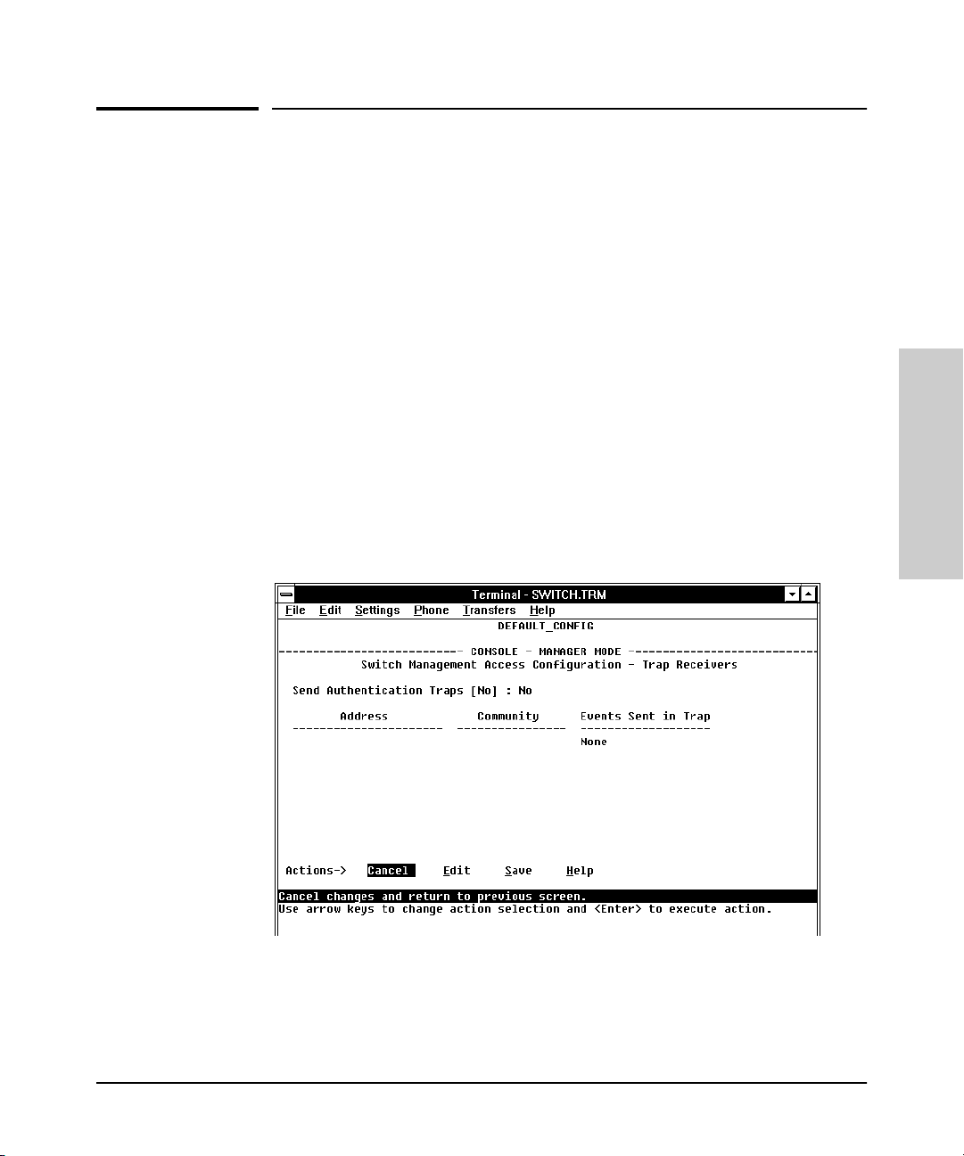
Configuring the Switch
Trap Receivers
Trap Receivers
From the switch console only you to configure up to ten IP management
stations (trap receivers) to receive SNMP trap packets sent from the switch.
Trap packets describe specific event types. (These events are the same as the
log messages displayed in the event log.) The Address and Community define
which management stations receive the traps.
If the Send Authentication Traps field is set to Ye s, an authentication trap is sent
to the addresses on the screen if any management station attempts an unauthorized access of the switch. Check the event log in the console interface to
help determine why the authentication trap was sent. (Refer to “Using the
Event Log To Identify Problem Sources” on page 8-12.)
To configure Trap Receivers from the switch console:
1. From the Console Main Menu, select
2. Switch Management Access Configuration (IP, SNMP, Console)...
3. Trap Receivers
Configuring the Switch
Figure 6-11. The Trap Receivers Configuration Screen (Default Values)
6-17
Page 94

Configuring the Switch
Trap Receivers
2. Press [E] (for Edit). The cursor moves to the Send Authentication Traps field.
3. Press the Space bar to enable (Yes) or disable (No) sending authentication
traps, then press [Tab] to move the cursor to the Address field.
4. Type in the IP address of a network management station to which you
want the switch to send SNMP trap packets, then press [Tab] to move the
cursor to the Community field.
5. Type in the name of the SNMP community to which the network management station belongs, then press [Tab] to move the cursor to the Events
field.
6. Use the Space bar to select the level of internal switch events that cause
trap packets to be sent:
Event Level Description
None (default) Send no log messages.
All Send all log messages.
Not INFO Send the log messages that are not information-only.
Configuring the Switch
Critical Send critical-level log messages.
Debug Reserved for HP-internal use.
7. Press [Enter], then press [S] (for S
ave) and return to the Main Menu.
6-18
Page 95

Configuring the Switch
Console/Serial Link
Console/Serial Link
From the switch console only you can configure the following console
terminal emulation and communication characteristics:
■ Enable or disable inbound Telnet access (default: enabled)
■ Enable or disable HP web browser interface access (default: enabled)
■ Specify:
• Terminal type (default: VT-100)
• Console screen refresh interval for statistics screens (the frequency
with which statistics are updated on the screen—default: 3 seconds)
• The types of events displayed in the console event log (default: all)
■ Customize the Console configuration for the PC or terminal you are using
for console access.
• Baud Rate (default: Speed Sense)
• Flow Control (default: XON/XOFF)
• Connection Inactivity Time (default: 10 minutes)
Configuring the Switch
In most cases, the default configuration is acceptable for standard operation.
If you need to change any of the above parameters, use the switch console.
Note If you change the Baud Rate or Flow Control settings for the switch, you
should make the corresponding changes in your console access device. Otherwise, you may lose connectivity between the switch and your terminal
emulator due to differences between the terminal and switch settings for these
two parameters.
6-19
Page 96

Configuring the Switch
Console/Serial Link
Configuring the Console/Serial Link from the Switch Console
This screen allows you to:
■ Enable or disable inbound Telnet and web browser interface access
■ Determine which log events will be displayed
■ Modify console and serial link parameters
To Access Console/Serial Link Features:
1. From the Console Main Menu, Select...
2. Switch Management Access Configuration (IP, SNMP, Console)...
4. Console/Serial Link Configuration
Configuring the Switch
6-20
Figure 6-12. The Console/Serial Link Configuration Screen (Default Values)
2. Press [E] (for E
dit). The cursor moves to the top field on the screen.
3. Refer to the online help provided with this screen for further information
on configuration options for these features.
4. When you have finished making changes to the above parameters, press
[Enter], then press [S] (for S
ave) and return to the Main Menu
Page 97

Enhancing Security By Configuring Authorized IP Managers
Configuring the Switch
Enhancing Security By Configuring
Authorized IP Managers
This feature enables you to enhance security on the switch by using IP
addresses to authorize which stations (PCs or workstations) are allowed to:
■ Access the switch’s web browser interface
■ Telnet into the switch’s console interface
■ Perform TFTP transfers of configurations and software updates into the
switch
Note This feature does not affect SNMP access to the switch by SNMP-authorized
management stations. (SNMP access is protected by community names and
an independent SNMP Authorized Managers list.)
You can configure:
■ Up to 10 authorized manager addresses, where each address applies to
either a single management station or a group of stations
■ Either a Manager or Operator access level
Configuring the Switch
Note This feature does not protect access to the switch through a modem or direct
Console (RS-232) port connection. Also, if the IP address assigned to an
authorized management station is configured in another station, the other
station can gain management access to the switch even though a duplicate IP
address condition exists. For these reasons, you should enhance your network’s security by keeping physical access to the switch restricted to authorized personnel, using the password features built into the switch, and
preventing unauthorized access to data on your management stations.
Access Levels
For each authorized manager address, you can configure either one of these
access levels:
■ Manager: Enables full access to all web browser and console interface
screens for viewing, configuration, and all other operations available in
these interfaces.
■ Operator: Allows view-only access from the web browser and console
interfaces. (This is the same access that is allowed by the switch’s operator-level password feature.)
6-21
Page 98

Configuring the Switch
Enhancing Security By Configuring Authorized IP Managers
Defining Authorized Management Stations
■ Authorizing Single Stations: The table entry authorizes a single man-
agement station to have IP access to the switch. To use this method, just
enter the IP address of an authorized management station in the Authorized Manager IP column, and leave the IP Mask set to
is the easiest way to use the Authorized Managers feature. (For more on
this topic, see “Configuring One Station Per Authorized Manager IP Entry”
on page 6-25.)
■ Authorizing Multiple Stations: The table entry authorizes a defined
group of stations to access the switch. This is useful if you want to easily
authorize several stations to have access to the switch without having to
type in an entry for every station. All stations in the group defined by the
one Authorized Manager IP table entry and its associated IP mask will
have the same access level—Manager or Operator. (For more on this
topic, see “Configuring Multiple Stations Per Authorized Manager IP
Entry” on page 6-25.)
To configure the switch for authorized manager access, enter the appropriate
Authorized Manager IP value, specify an IP Mask, and select either
Operator for the Access Level. The IP Mask determines how the Authorized
Configuring the Switch
or
Manager IP value is used to define authorized IP addresses for management
station access.
255.255.255.255. This
Manager
Overview of IP Mask Operation
The default IP Mask is 255.255.255.255 and allows switch access only to a
station having an IP address that is identical to the Authorized Manager IP
parameter value. (“255” in an octet of the mask means that only the exact value
in the corresponding octet of the Authorized Manager IP parameter is allowed
in the IP address of an authorized management station.) However, you can
alter the mask and the Authorized Manager IP parameter to specify ranges of
authorized IP addresses. For example, a mask of
255.255.255.
the Authorized Manager IP parameter allows a range of 0 through 255 in the
4th octet of the authorized IP address, which enables a block of up to 256 IP
addresses for IP management access. A mask of
255.255.255.25
of a given Authorized Manager IP address to authorize four IP addresses for
management station access. The details on how to use IP masks are provided
under “Building IP Masks” on page 6-24.
Note The IP Mask is a method for recognizing whether a given IP address is
authorized for management access to the switch. This mask serves a different
purpose than IP subnet masks and is applied in a different manner.
6-22
0
and any value for
2
uses the 4th octet
Page 99

Enhancing Security By Configuring Authorized IP Managers
Configuring the Switch
Configuring IP Authorized Managers in the Web Browser Interface
1. Click here.
2. Click here.
3. Enter an Authorized
Manager IP address
here.
6. Click here to add your entry to the list.
4. Use the default mask
Figure 6-13. Example of an Authorized IP Manager List with Manager and Operator
Assignments
Configuring IP Authorized Managers in the Console Interface
From the console Main Menu, select:
2. Switch Management Access Configuration (IP, SNMP, Console) . . .
6. IP Authorized Managers
to allow access by on e
management station , or
edit the mask to allow
access by a group of
management stations
(page 6-24).
Example of entry with default IP mask (allowing access
by only one station
5. Select Manager level or
Operator level access
(page 6-21.)
.
Configuring the Switch
6-23
Page 100

Configuring the Switch
Enhancing Security By Configuring Authorized IP Managers
Figure 6-14. Example of How To Add an Authorized Manager Entry
1. Select Add to add an authorized manager
to the list.
Configuring the Switch
2. Enter an Authorized Manager IP address here.
3. Use the default mask to allow access by one
management device, or edit the mask to allow
access by a block of management devices. See
“Building IP Masks” below.
4. Select Manager or Operator access.
5. Press [Enter], then [S] (for Save) to configure the IP
Authorized Manager entry.
Figure 6-15. Example of How To Add an Authorized Manager Entry (Continued)
Editing or Deleting an Authorized Manager Entry. Go to the IP Managers List screen (figure 6-14), highlight the desired entry, and press [E] (for
or [D] (for
Delete).
Edit)
Building IP Masks
The IP Mask parameter controls how the switch uses an Authorized Manager
IP value to recognize the IP addresses of authorized manager stations on your
network.
6-24
 Loading...