

Page 1

Setup Guide
hp StorageWorks
3800ux/7100ux
Optical Jukebox
First Edition (May 2004)
Part Number: AA969-96003
This guide describes procedures for unpacking, installing, configuring, and troubleshooting
installation issues for the HP StorageWorks 3800ux/7100ux Optical Jukebox.
Page 2

© Copyright 2004 Hewlett-Packard Development Company, L.P.
Hewlett-Packard Company makes no warranty of any kind with regard to this material, including, but not limited to,
the implied warranties of merchantability and fitness for a particular purpose. Hewlett-Packard shall not be liable for
errors contained herein or for incidental or consequential damages in connection with the furnishing, performance,
or use of this material.
This document contains proprietary information, which is protected by copyright. No part of this document may be
photocopied, reproduced, or translated into another language without the prior written consent of Hewlett-Packard.
The information contained in this document is subject to change without notice. The only warranties for HP products
and services are set forth in the express warranty statements accompanying such products and services. Nothing
herein should be construed as constituting an additional warranty.
Microsoft®, MS-DOS®, MS Windows® and Windows® are U.S. registered trademarks of Microsoft Corporation.
UNIX® is a registered trademark of The Open Group.
Hewlett-Packard Company shall not be liable for technical or editorial errors or omissions contained herein. The
information is provided “as is” without warranty of any kind and is subject to change without notice. The warranties
for Hewlett-Packard Company products are set forth in the express limited warranty statements for such products.
Nothing herein should be construed as constituting an additional warranty.
Printed in the U.S.A.
HP StorageWorks 3800ux/7100ux Optical Jukebox Setup Guide
First Edition (May 2004)
Part Number: AA969-96003
Regulatory Model Number: N3620N4Z
Page 3

Contents
About this Guide. . . . . . . . . . . . . . . . . . . . . . . . . . . . . . . . . . . . . . . . . . . . . . . . . . . .5
Related documentation . . . . . . . . . . . . . . . . . . . . . . . . . . . . . . . . . . . . . . . . . . . . . . . . . . . . . . . 6
Conventions . . . . . . . . . . . . . . . . . . . . . . . . . . . . . . . . . . . . . . . . . . . . . . . . . . . . . . . . . . . . . . . 6
Document conventions. . . . . . . . . . . . . . . . . . . . . . . . . . . . . . . . . . . . . . . . . . . . . . . . . . . . 6
Text symbols . . . . . . . . . . . . . . . . . . . . . . . . . . . . . . . . . . . . . . . . . . . . . . . . . . . . . . . . . . . 7
Getting help . . . . . . . . . . . . . . . . . . . . . . . . . . . . . . . . . . . . . . . . . . . . . . . . . . . . . . . . . . . . . . . 8
HP technical support . . . . . . . . . . . . . . . . . . . . . . . . . . . . . . . . . . . . . . . . . . . . . . . . . . . . . 8
HP storage web site . . . . . . . . . . . . . . . . . . . . . . . . . . . . . . . . . . . . . . . . . . . . . . . . . . . . . . 8
HP authorized reseller . . . . . . . . . . . . . . . . . . . . . . . . . . . . . . . . . . . . . . . . . . . . . . . . . . . . 9
1 Unpacking . . . . . . . . . . . . . . . . . . . . . . . . . . . . . . . . . . . . . . . . . . . . . . . . . . . . . . .11
Selecting an installation site . . . . . . . . . . . . . . . . . . . . . . . . . . . . . . . . . . . . . . . . . . . . . . . . . . 12
Removing the packing materials . . . . . . . . . . . . . . . . . . . . . . . . . . . . . . . . . . . . . . . . . . . . . . 14
2 Installation . . . . . . . . . . . . . . . . . . . . . . . . . . . . . . . . . . . . . . . . . . . . . . . . . . . . . . .21
Identifying product components. . . . . . . . . . . . . . . . . . . . . . . . . . . . . . . . . . . . . . . . . . . . . . . 22
Identifying panel features. . . . . . . . . . . . . . . . . . . . . . . . . . . . . . . . . . . . . . . . . . . . . . . . . . . . 24
Front panel features and descriptions. . . . . . . . . . . . . . . . . . . . . . . . . . . . . . . . . . . . . . . . 24
Side panel features and descriptions . . . . . . . . . . . . . . . . . . . . . . . . . . . . . . . . . . . . . . . . 25
Getting connected. . . . . . . . . . . . . . . . . . . . . . . . . . . . . . . . . . . . . . . . . . . . . . . . . . . . . . . . . . 27
3 Configuration . . . . . . . . . . . . . . . . . . . . . . . . . . . . . . . . . . . . . . . . . . . . . . . . . . . . .33
Using the jukebox on your host system . . . . . . . . . . . . . . . . . . . . . . . . . . . . . . . . . . . . . . . . . 34
Connection to Windows 2000 and 2003 Server versions (32- and 64-bit systems) . . . . 34
Connection to HP-UX (11.x) . . . . . . . . . . . . . . . . . . . . . . . . . . . . . . . . . . . . . . . . . . . . . . 35
Obtaining HP-UX patches. . . . . . . . . . . . . . . . . . . . . . . . . . . . . . . . . . . . . . . . . . . . . 35
Installing the schgr driver . . . . . . . . . . . . . . . . . . . . . . . . . . . . . . . . . . . . . . . . . . . . . 35
Formatting and mounting UDO rewritable disks . . . . . . . . . . . . . . . . . . . . . . . . . . . 36
Connection to Sun Solaris, IBM AIX, Tru-64, and Linux. . . . . . . . . . . . . . . . . . . . . . . . 37
Loading UDO media. . . . . . . . . . . . . . . . . . . . . . . . . . . . . . . . . . . . . . . . . . . . . . . . . . . . . . . . 38
Contents
3HP StorageWorks 3800ux/7100ux Optical Jukebox Setup Guide
Page 4

Contents
4 Troubleshooting Installation. . . . . . . . . . . . . . . . . . . . . . . . . . . . . . . . . . . . . . . . . . .41
Resolving installation issues. . . . . . . . . . . . . . . . . . . . . . . . . . . . . . . . . . . . . . . . . . . . . . . . . . 42
Using HP StorageWorks Library and Tape Tools . . . . . . . . . . . . . . . . . . . . . . . . . . . . . . . . . 45
Glossary. . . . . . . . . . . . . . . . . . . . . . . . . . . . . . . . . . . . . . . . . . . . . . . . . . . . . . . . .47
Index . . . . . . . . . . . . . . . . . . . . . . . . . . . . . . . . . . . . . . . . . . . . . . . . . . . . . . . . . . .49
4 HP StorageWorks 3800ux/7100ux Optical Jukebox Setup Guide
Page 5

About This
Guide
This user guide provides information to help you:
■ Unpack the jukebox
■ Install and configure the jukebox
■ Load media
■ Troubleshoot installation issues
About this Guide
About this Guide
“About This Guide” topics include:
■ Related documentation, page 6
■ Conventions, page 6
■ Getting help, page 8
5HP StorageWorks 3800ux/7100ux Optical Jukebox Setup Guide
Page 6

About this Guide
Related documentation
In addition to this guide, HP provides corresponding information:
■
HP StorageWorks Optical 3800ux/7100ux Jukebox User’s Guide
■
HP StorageWorks Optical 3800ux/7100ux Jukebox Getting Started Poster
Conventions
Conventions consist of the following:
■ Document convention s
■ Text symbols
Document conventions
This document follows the conventions in Table 1.
Table 1: Document conventions
Element Convention
Cross-reference links
Key and field names, menu items, buttons, and
dialogue box titles
File names, application names, and text
emphasis
User input, commands and directory names,
and system responses (output and messages)
Variables
Web site addresses Blue underlined sans serif font text
Blue text:
Bold
Italics
Monospace font
COMMAND NAMES
font unless they are case sensitive
<monospace, italic font>
(
http://www.hp.com
Figure 1
are uppercase monospace
)
6 HP StorageWorks 3800ux/7100ux Optical Jukebox Setup Guide
Page 7

Text symbols
About this Guide
The following symbols may be found in the text of this guide. They have the
following meanings:
WARNING: Text set off in this manner indicates that failure to follow
directions in the warning could result in bodily harm or death.
Caution: Text set off in this manner indicates that failure to follow directions
could result in damage to equipment or data.
Note: Text set off in this manner presents commentary, sidelights, or interesting points
of information.
HP StorageWorks 3800ux/7100ux Optical Jukebox Setup Guide
7
Page 8

About this Guide
Getting help
If you still have a question after reading this guide, contact an HP authorized
service provider or access our web site:
HP technical support
Telephone numbers for worldwide technical support are listed on the following
HP web site:
Note: For continuous quality improvement, calls may be recorded or monitored.
Be sure to have the following information available before calling:
■ Technical support registration or contract number (if applicable)
■ Product serial numbers
■ Product model names and numbers
■ Applicable error messages
http://www.hp.com
http://www.hp.com/support/
.
.
■ Operating system type and revision level
■ Detailed, specific questions
■ HP StorageWorks Library & Tape Tools support ticket (if applicable)
HP storage web site
The HP web site has the latest information on this product. Access storage at:
http://www.hp.com/country/us/eng/p rodserv/storage.html
select the appropriate product or solution. You can also visit
http://www.hp.com/go/udo
8 HP StorageWorks 3800ux/7100ux Optical Jukebox Setup Guide
.
. From this web site,
Page 9

HP authorized reseller
For the name of your nearest HP authorized reseller:
■ In the United States, call 1-800-345-1518
■ In Canada, call 1-800-263-5868
■ Elsewhere, see the HP web site for locations and telephone numbers:
http://www.hp .com
About this Guide
.
HP StorageWorks 3800ux/7100ux Optical Jukebox Setup Guide
9
Page 10

About this Guide
10 HP StorageWorks 3800ux/7100ux Optical Jukebox Setup Guide
Page 11

Unpacking
This chapter describes the following:
■ Selecting an installation site, page 12
■ Removing the packing materials, page 1 4
1
11HP StorageWorks 3800ux/7100ux Optical Jukebox Setup Guide
Page 12
Unpacking
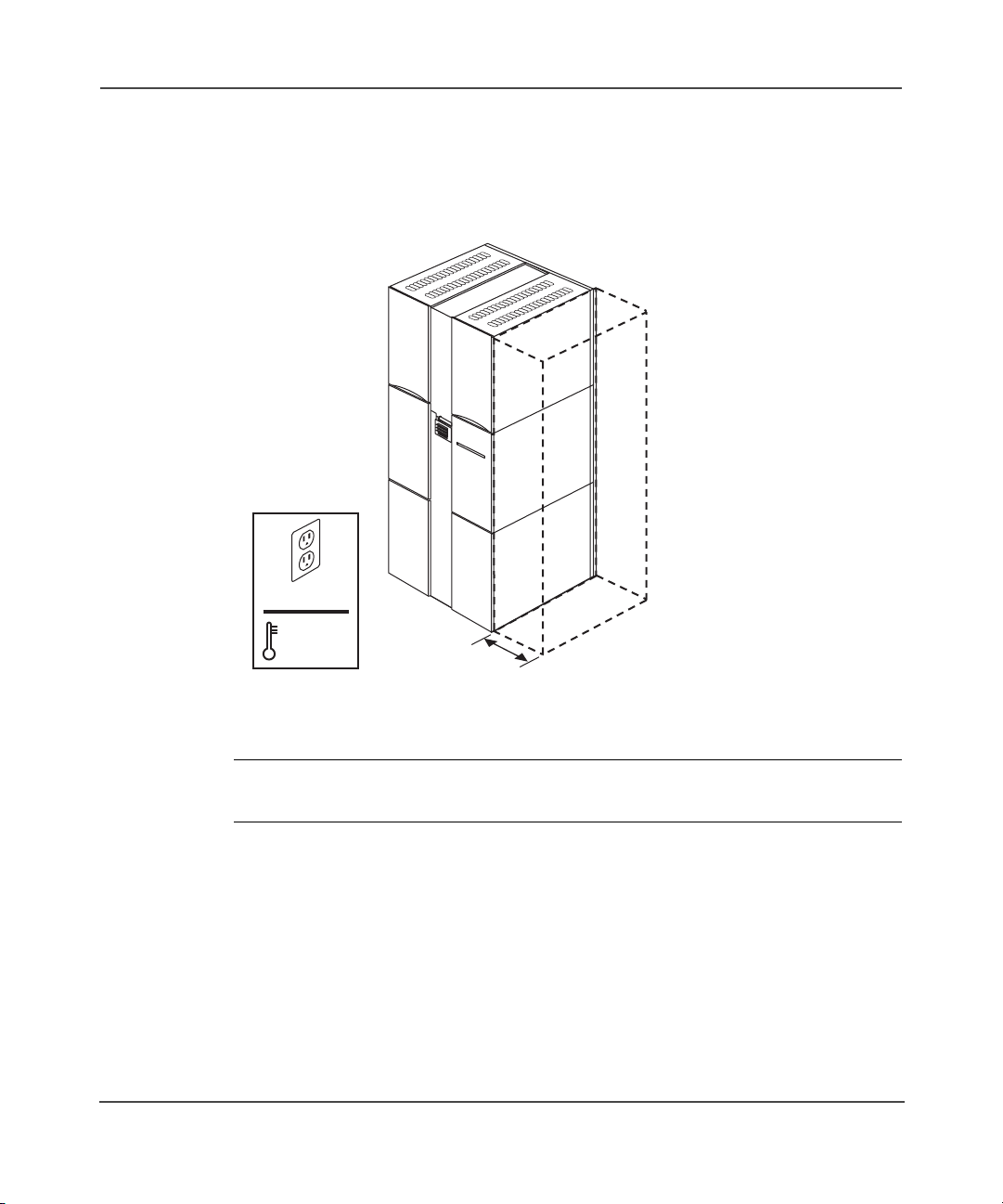
Selecting an installation site
Select an installation site, noting the environmental considerations (see Figure 1
and Table 2). Sufficient clearance is necessary for installation access.
100-240V
59-95ºF
10-35ºC
Figure 1: Environmental considerations
Note: Locate the AC outlet near the jukebox. The AC power cord is this product’s main
AC disconnect device and must be easily accessible at all times.
12 HP StorageWorks 3800ux/7100ux Optical Jukebox Setup Guide
0.9 m
(3 ft)
Page 13

Unpacking
Table 2: Location criteria
Specification Description
Clearance Enough room to comfortably insert disks
in the mailslot and 0.9 m (3 ft) on the
right side for installation access.
Power requirements
■ Line voltage: 100 to 240 VAC
■ Line frequency: 50 to 60 Hz
■ Power consumption:
560 W maximum
Temperature:
■ Operating temperature
■ Non-operating temperature (without
media)
■ 10ºC to 35ºC (50ºF to 95ºF)
■ -40ºC to 60ºC (-40ºF to 140ºF)
Humidity:
■ Operating humidity
■ Non-operating humidity (without
■ 10% to 80% RH
■ 5% to 90% RH
media)
Light Avoid very bright or concentrated light
as it can interfere with the optical
sensors.
Air quality
Minimal sources of particulate
contamination. Avoid areas near
frequently used doors and walkways,
Caution: Excessive dust and
debris can damage optical
media and drives.
stacks of supplies that collect dust,
printers that create paper dust, and
smoke-filled rooms.
13HP StorageWorks 3800ux/7100ux Optical Jukebox Setup Guide
Page 14
Unpacking
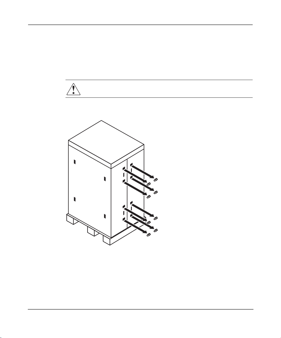
Removing the packing materials
Remove the 3800ux/7100ux jukebox packing materials.
1. Cut the two plastic bands that secure the jukebox and packing materials to the
pallet.
WARNING: The plastic bands are under tension and may snap away when
cut. Wear safety goggles when cutting the bands.
2. Remove the eight cardboard box retaining clips (see Figure 2).
Figure 2: Removing the retaining clips
14 HP StorageWorks 3800ux/7100ux Optical Jukebox Setup Guide
Page 15
Unpacking
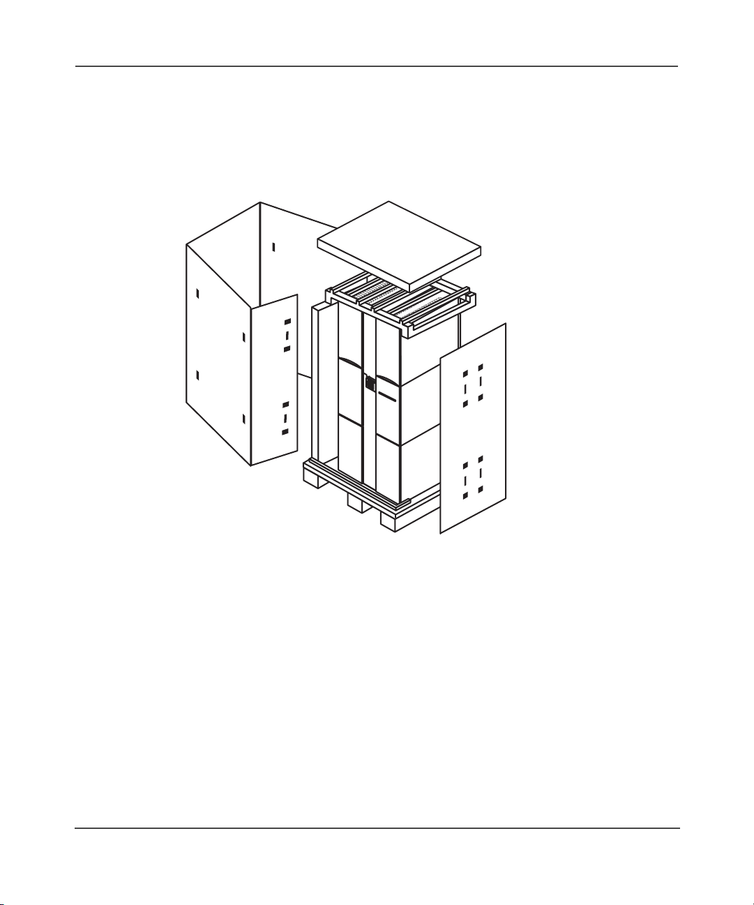
3. Lift the cardboard box top cover straight up and off of the main carton (see
Figure 3).
4. Unwrap the cardboard box from around the jukebox (see Figure 3).
5. Remove the foam cap from the top of the jukebox (see Figure 3).
Figure 3: Remove the cardboard pieces
6. Using at least two people, remove the ramp from the pallet.
15HP StorageWorks 3800ux/7100ux Optical Jukebox Setup Guide
Page 16

Unpacking
7. Secure the ramp to the pallet using the pallet bolts (see Figure 4).
Figure 4: Securing the pallet ramp
16 HP StorageWorks 3800ux/7100ux Optical Jukebox Setup Guide
Page 17

Unpacking
8. Using a Torx T-15 screwdriver, remove the screws securing the access panels
to the lower right and left sides of the cabinet (see Figure 5).
Figure 5: Removing the access panels
17HP StorageWorks 3800ux/7100ux Optical Jukebox Setup Guide
Page 18

Unpacking
9. Remove the 4 bolts securing the jukebox to the pallet (see Figure 6).
Figure 6: Removing the pallet bolts
WARNING: Do not move the jukebox without additional help or an
appropriately rated lift device. The jukebox weights approximately 288 kg
(635 lb).
10. Using at least two people, carefully roll the jukebox down the ramp and guide
it to the installation site.
18 HP StorageWorks 3800ux/7100ux Optical Jukebox Setup Guide
Page 19

Unpacking
11. Stabilize the jukebox by installing the four wheel chocks. Spread the chocks
apart slightly and slide them around the bottom of each wheel (see Figure 7).
Figure 7: Installing the wheel chocks
12. Remove the antistatic bag covering the jukebox.
Note: Inspect the jukebox for any damage that may have occurred during shipment.
Pay special attention to areas behind any scuffs on the anti-static bag. If damage is
detected, contact your authorized service representative.
13. Store the packing materials for future shipment.
19HP StorageWorks 3800ux/7100ux Optical Jukebox Setup Guide
Page 20

Unpacking
20 HP StorageWorks 3800ux/7100ux Optical Jukebox Setup Guide
Page 21

Installation
This chapter describes the following:
■ Identifying product components, page 22
■ Identifying panel features, page 24
■ Getting connected, page 27
2
21HP StorageWorks 3800ux/7100ux Optical Jukebox Setup Guide
Page 22

Installation
Identifying product components
The components listed in Table 3 may be supplied with the jukebox, depending on
the configuration.
Note: Visit
including accessories and upgrade options.
Table 3: Supplied accessories
Power cord U.S. power cord only
SCSI terminators Low-voltage differential SCSI terminators
UDO media One rewritable 30 GB cartridge, HP
Documentation CD CD containing the user’s guide, and
Getting started poster Quick reference for preparing the
Setup guide Manual includes procedures for
Miscellaneous information May include data sheets, upgrade
http://www.hp.com/g o/udo
Component Description
for additional information for your jukebox,
to terminate the SCSI chain
part number Q2031A
Note: HP UDO 30GB Write Once
media is also available to order. The
part number is Q2030A
web links to product registration,
diagnostics and technical support
jukebox for operation
unpacking, installing, and configuring
the jukebox
information, production information,
and additional promotions
22 HP StorageWorks 3800ux/7100ux Optical Jukebox Setup Guide
Page 23

Installation
The components listed in Table 4 are not supplied with the jukebox, but are
needed for operation.
Table 4: Needed components
Component Description
SCSI cables High-density 68-pin (Micro D) connector
for low-voltage differential interfaces
Host Bus Adapter (HBA) Low-voltage differential SCSI (LVDS) with
a free address for each drive in the
jukebox, plus one additional address.
For example, an HBA would need 5 free
addresses for a 4-drive jukebox.
Note: The HBA must be dedicated to the
jukebox and cannot be shared with
other devices.
A single-ended (SE) HBA can be used
with this LVDS device. However, to
ensure optimum performance, HP
recommends using an LVDS HBA to take
advantage of higher data transfer rates.
If an SE HBA is used, the maximum
cable length will be limited to 3 meters.
Note: If the jukebox is placed on a bus
with an SE peripheral, the bus will run in
SE mode even if the HBA is LVDS. For a
10-drive jukebox, HP recommends one
HBA per bus.
Power cord Localized power cord as required
Application software Required to operate your jukebox.
Consult with your sales representative to
identify the software that best meets your
needs.
23HP StorageWorks 3800ux/7100ux Optical Jukebox Setup Guide
Page 24

Installation
Identifying panel features
Identify the following panel features before you install the jukebox (see Figure 8
and Figure 9 on page 25).
Front panel features and descriptions
1
2
3
4
1 Display
2 Mailslot
3 Selection buttons
4 Activity indicator
Figure 8: Front panel features
■ Display—Communicates control panel and status information.
■ Mailslot—Used to insert and remove disks from the jukebox.
■ Selection buttons—Used to access jukebox menus.
■ Activity indicator—Lit to indicate power and drive status, as well as the
occurrence of faults.
24 HP StorageWorks 3800ux/7100ux Optical Jukebox Setup Guide
Page 25

Side panel features and descriptions
Installation
2
1
1 Active bus indicator
2 SCSI ports
3 Power cord strain relief clip
4 Product serial number label
Figure 9: Side panel features
8
3
4
5 Access panel and mounting screws
6 Cable access hole
7 Power switch
8 Power receptacle
7
6
5
25HP StorageWorks 3800ux/7100ux Optical Jukebox Setup Guide
Page 26

Installation
■ Active bus indicator—Lit when the SCSI bus is acti ve.
■ SCSI ports—68-pin high-density SCSI connectors (Micro D-type). Used for
attaching the SCSI cable from the jukebox to the host computer. One port
must have a SCSI cable connected, and the other must have a SCSI terminator
connected to it.
■ Power cord clip—Used to route the power cord away from other connectors
and provide strain relief for the power cord connection.
■ Product serial number label—Needed for service calls. Write down your
jukebox serial number before you call your service representative.
■ Access panel and mounting screws—Covers the interface and power
connection components. The panel is secured by two screws on the lower
corners.
Note: T w o scre ws secure the customer access panel to the side of jukebox during
shipment from the factory. These screws are removed during unpacking but
should be replaced after installation is complete. If the jukebox is ever reshipped,
these screws must be in place to properly secure the access panel.
■ Cable access hole—Used to pass SCSI and power cables through the cabinet
to the inside of the jukebox.
■ Power switch—Turns power to the jukebox on and off.
■ Power receptacle—Used for connecting the power cord to the jukebox.
Located on the bottom of the power distribution assembly.
26 HP StorageWorks 3800ux/7100ux Optical Jukebox Setup Guide
Page 27

Getting connected
1. Using a flat-slotted screwdriver, remove the two screws securing the access
panel to the lower right of the cabinet (see Figure 10).
Installation
Figure 10: Removing the access panel
2. Connect the jukebox to your host computer and terminate the last device in
the SCSI chain (see Figure 11).
Figure 11: Connecting to the host
27HP StorageWorks 3800ux/7100ux Optical Jukebox Setup Guide
Page 28

Installation
For a 10-drive jukebox, HP recommends one HBA per bus. This would
require attaching two SCSI cables between the host and the jukebox, If the
customer is limited to just one HBA, then the two busses must be
daisy-chained together (see Figure 12).
Daisy-chain cable
Terminator
SCSI cable to host
Figure 12: Daisy-chaining 2 busses with a single HBA
Note: The maximum cable length for LVDS is 12 meters. The maximum cable length for
SE is 3 meters.
WARNING: This product can only be used with an HP approved power cord
for your specific geographic region. Use of a non-HP approved power cord
may result in: 1) noncompliance with individual, country-specific safety
requirements; 2) insufficient conductor ampacity that could result in
overheating with potential personal injury and/or property damage; and 3) a
fractured power cord which could cause the internal contacts to be exposed,
which potentially could subject the user to a shock hazard. HP disclaims all
liability when HP approved power cords are not used.
3. Plug the socket end of the power cord into the po wer recept acle on the bottom
of the power distribution assembly (see Figure 13).
4. Route the power cord through the clip and close it securely around the cord
(see Figure 13).
5. Continue routing down through the long cable slot at the bottom of the right
side panel, and out through the access hole at the lower back of the jukebox
(see Figure 13).
28 HP StorageWorks 3800ux/7100ux Optical Jukebox Setup Guide
Page 29

Figure 13: Connecting and routing the power cord
Installation
29HP StorageWorks 3800ux/7100ux Optical Jukebox Setup Guide
Page 30

Installation
6. Connect power to the jukebox. Power on the jukebox and then power on the
host system (see Figure 14).
Figure 14: Powering on the jukebox
7. If necessary, set the jukebox and drive SCSI ID’s by selecting READY >
ADMIN * > SCSI ID’s * from the jukebox menu. Ensure that there are no
SCSI ID conflicts with existing devices.
Note: The default administrative password is “000 000 000”.
The default SCSI IDs for a 4- or 6-drive UDO jukebox are:
■ Jukebox = 6
■ Drive 1 = 5
■ Drive 2 = 4
■ Drive 3 = 3
■ Drive 4 = 2
■ Drive 5 = 1 (if present)
30 HP StorageWorks 3800ux/7100ux Optical Jukebox Setup Guide
Page 31

■ Drive 6 = 0 (if present)
The default SCSI IDs for a 10-drive UDO jukebox are:
■ Jukebox = 6
■ Bus 1:
—Drive 1 = 5
—Drive 2 = 4
—Drive 3 = 3
—Drive 4 = 2
■ Bus 2:
—Drive 5 = 5
—Drive 6 = 4
—Drive 7 = 3
— Drive 8 - 2
—Drive 9 = 1
—Drive 10 = 0
Installation
Note: If the jukebox has been daisy-chained to accommodate for a single HBA, the
SCSI IDs must be changed from the defaults to avoid conflicts.
The default SCSI IDs for a 10-drive mixed media jukebox are:
■ Jukebox = 6
■ Bus 1:
—Drive 1 = 5
—Drive 2 = 4
—Drive 3 = 3
—Drive 4 = 2
—Drive 5 = 1
—Drive 6 = 0
31HP StorageWorks 3800ux/7100ux Optical Jukebox Setup Guide
Page 32

Installation
■ Bus 2:
—Drive 7 = 5
— Drive 8 - 4
—Drive 9 = 3
—Drive 10 = 2
Note: If the jukebox has been daisy-chained to accommodate for a single HBA, the
SCSI IDs must be changed from the defaults to avoid conflicts.
32 HP StorageWorks 3800ux/7100ux Optical Jukebox Setup Guide
Page 33

Configuration
This chapter describes the following:
■ Using the jukebox on your host system, page 34
■ Loading UDO media, page 38
3
33HP StorageWorks 3800ux/7100ux Optical Jukebox Setup Guide
Page 34

Configuration
Using the jukebox on your host system
The following procedures describe how to configure the jukebox with your host
operating system.
Note: To use 30-GB disks, your operating system or application software must support
8,192 byte-per-sector media. HP-UX 11.x versions provide this natively with kernel
patches as applicable (see “Obtaining HP-UX patches” on page 35).
Connection to Windows 2000 and 2003 Server versions (32- and 64-bit systems)
Caution: To avoid software conflicts due to RSM drivers claiming the device,
do not attempt to attach a UDO jukebox to a Windows system before
completing the following steps.
The Windows operating systems do not offer any native driver support for the
jukebox robotics, or file systems (NTFS) for the 8K sector sized UDO media.
Though native support is not offered b y the Windows operating systems, there are
important steps required in order for your device to operate correctly, including
after third party software has been installed.
1. Disable Removable Storage Manager and reboot the system before attaching
the jukebox.
2. Windows 2000 sys t ems require a minimum of Service Pack 4 to be installed
as well as Microsoft Hotfix, as described in Knowledge Base Article
KB831293. This patch is required for the Windows operating system to
recognize an 8K sector sized device.
Note: If you are using a supported software application, the UDF driver for the
Windows file system is not required.
34 HP StorageWorks 3800ux/7100ux Optical Jukebox Setup Guide
Page 35

Connection to HP-UX (11.x)
The following procedures are for configuring an HP-UX operating system to use
native drivers with UDO jukeboxes.
Obtaining HP-UX patches
Your HP-UX system may require software patches to ensure that the standalone
UDO drive will install and operate correctly with your system. HP-UX versions
11.0, 11.11 and 11.23 require patches. To view the most up-to-date list of patch
requirements, visit
http://www.hp.com/go/support
go to
patch locations.
Note: HP-UX versions 11.x provide limited native support for jukeboxes, including file
system support for rewritable media and a SCSI driver (schgr) for the jukebox
robotics.
Note: When using a third party application, HP recommends you consult with the
application vendor for configuration requirements and recommendations.
http://www.hp.com/go/udo
Configuration
. To download required patches,
or refer to your HP-UX documentation for
Installing the schgr driver
The schgr driver is an HP-UX native SCSI driver that allows commands to be
sent to a media changer.
1. Log on to the system as root.
2. Initialize SAM by typing sam at the command line.
Note: If you are not familiar with using SAM, consult your HP-UX documentation.
3. Select the following items from the menus that are displayed:
■ Kernel Configuration
■ Drivers
4. Scroll down to the entry “schgr”.
35HP StorageWorks 3800ux/7100ux Optical Jukebox Setup Guide
Page 36

Configuration
5. Verify that the current state column shows the driver as “out”. If the state is
listed as “in”, skip the remaining schgr installation steps.
6. Highlight “schgr”. From the Actions menu select Add Driver(s) to Kernel.
7. Verify that pending state column is now listing “in”.
8. Return to the Actions menu and select Process New Kernel. This will install
the driver, rebuild the kernel, and request a reboot of the system in order to
move the kernel into place.
Formatting and mounting UDO rewritable disks
After loading the drive with media from the Operator Control Panel (OCP) or by
using the HP-UX MC utility, you can format and mount the media as you would
any other disk drive in HP-UX.
1. Identify the SCSI address of the desired drive by inspecting the output of
ioscan-fn:
a. Scroll through the ioscan output and look for the entry “AA961A” in
the Device Description column.
b. Look for the corresponding /dev/rdsk and /dev/dsk entries.
Note: If the /dev/rdsk and /dev/dsk entries are not listed, it may be necessary to
perform an “insf -e” to build the appropriate device files.
c. Record the device file information listed, such as:
disk 4 0/6/0/0.0.0 sdisk CLAIMED DEVICE HP AA961A
/dev/dsk/c4t0d0 /dev/rdsk/c4t0d0
2. Format and mount the disk using the bolded device file information shown in
the above ex ample.
a. Create a directory to use as a mount point, such as mkdir/mnt/UDO.
b. Format the disk using the newfs command:
newfs -F vxfs /dev/rdsk/c4t0d0
c. Mount the disk to the directory you created in step 2.a, such as
mount /dev/dsk/c4t0d0 /mnt/UDO.
Your UDO disk is now formatted and mounted, and can be used on HP-UX.
36 HP StorageWorks 3800ux/7100ux Optical Jukebox Setup Guide
Page 37

Connection to Sun Solaris, IBM AIX, Tru-64, and Linux
Use third-party drivers. No native support is available with these operating
systems.
Note: For operating systems requiring third party drivers, HP recommends attaching
the jukebox to the host with the host powered off. Power on the jukebox and then power
on the server.
Configuration
37HP StorageWorks 3800ux/7100ux Optical Jukebox Setup Guide
Page 38

Configuration
Loading UDO media
Note: Label all disks before loading them into the jukebox. Some application software
packages require that you load and eject disks by using instructions in the software. If
you use a software application to manage files in the jukebox, check the software
documentation before proceeding with these steps.
1. Start with READY, LOAD *, or EJECT * displaying on the control panel.
2. Press LOAD on the jukebox control panel. The mailslot on the front panel
opens.
3. Load UDO media into the drive by inserti ng the disk gently but f irmly into the
mailslot, shutter end first, and with the side you want to access f acing up (A or
B). See Figure 15.
An incorrectly inserted disk will be rejected with CART IN WRONG
displaying briefly.
Figure 15: Loading media
38 HP StorageWorks 3800ux/7100ux Optical Jukebox Setup Guide
Page 39

Configuration
4. LOAD SLOT # will display, with # flashing to indicate the number of the
first available storage slot in the jukebox. To select this storage slot number,
press LOAD or ENTER. To choose a different storage slot, press NEXT or
PREV until the desired slot number displays, and then press ENTER.
5. LOADING displays as the jukebox moves the disk to a slot. After the disk is
loaded into the storage slot, LOAD * displays. You can now load additional
disks by inserting them into the mailslot and repeating step 4 until you are
finished loading disks.
6. Press CANCEL to return to the READY state.
Note: For detailed information on using or ordering HP UDO media, refer to the
getting started poster and the user’s guide that shipped with the jukebox.
39HP StorageWorks 3800ux/7100ux Optical Jukebox Setup Guide
Page 40

Configuration
40 HP StorageWorks 3800ux/7100ux Optical Jukebox Setup Guide
Page 41

Troubleshooting Installation
This chapter describes the following:
■ Resolving installation issues, page 42
■ Using HP StorageWorks Library and Tape Tools, page 45
4
41HP StorageWorks 3800ux/7100ux Optical Jukebox Setup Guide
Page 42

Troubleshooting Installation
Resolving installation issues
If the procedures in Table 5 do not address or resolve your problem, visit
http://www.hp.com/go/udo
support (see “Getting help” on page 8).
Table 5: Troubleshooting installation
Problem Solution
Power
Jukebox will not power on
Host computer system does not
recognize the jukebox or the drives
for additional assistance, or contact HP technical
■ Check that the power indicator light
on the control panel is on. If it is not,
make sure the power switch on the
side panel is on.
■ Replace the power cord.
■ Ensure the jukebox is not in a error
or failed state. If so, troubleshoot the
error before continuing.
■ Ensure the jukebox is connected and
powered on. The jukebox must be
on when booting the host computer
for the jukebox to be recognized.
■ If the jukebox is the last device on
the SCSI bus, check that it has been
terminated and that the maximum
cable length has not been
exceeded.
■ Check SCSI ID assignments and
resolve any conflicts.
■ Ensure you are connected to the
correct SCSI bus type. UDO
jukeboxes are LVDS devices.
■ If using a narrow (8-bit) HBA, make
sure that all addresses are in the
range 0 through 7.
■ For Windows operating systems, use
the device manager to rediscover
the jukebox.
■ For HP-UX, use ioscan to verify
that the HBA and attached devices
are claimed.
■ For other operating systems, refer to
the system administrators guide for
diagnosing missing peripherals.
42 HP StorageWorks 3800ux/7100ux Optical Jukebox Setup Guide
Page 43

Table 5: Troubleshooting installation (Continued)
Problem Solution
■ Check that the application software
■ Check that the device is properly
■ Power cycle the jukebox and power
The power-on selftest failed and
DEVICE FAILED displays.
Power to the jukebox failed while a disk
was in the drive and the display did not
return to
READY after the power came
■ Power cycle the jukebox.
■ If the power-on test continues to fail,
■ Power cycle the jukebox.
■ If READY does not display
back on.
Troubleshooting Installation
is compatible with the jukebox.
installed and configured using HP
StorageWorks Library & Tape Tools,
available from
http://www.hp.com/support/tape
tools
.
down the host. Wait until the
jukebox completes its power cycle
before powering up the host.
press
ENTER, write down the
displayed error code, and contact
your support representative.
(power-on test is unsuccessful),
switch off the power and contact
your support representative.
Caution: Do not move the unit!
Moving the unit risks damaging
the optical drive.
No display messages. ■ Ensure that the power cord is
connected.
■ Ensure that the power switch is on.
■ Power cycle the jukebox.
43HP StorageWorks 3800ux/7100ux Optical Jukebox Setup Guide
Page 44

Troubleshooting Installation
Table 5: Troubleshooting installation (Continued)
Connection
Other SCSI devices no longer work
when the jukebox is installed
Problem Solution
■ Check SCSI ID assignments and
resolve any conflicts.
■ Ensure that the SCSI ID for the HBA
is different from that of the jukebox.
■ Check for proper SCSI cabling and
termination.
■ Ensure the maximum cable length
for the bus has not been exceeded
(12 meters for LVDS and 3 meters
for SE).
44 HP StorageWorks 3800ux/7100ux Optical Jukebox Setup Guide
Page 45

Using HP StorageWorks Library and Tape Tools
HP StorageWorks Library and Tape Tools (L&TT) is a robust diagnostic tool for
tape mechanisms, tape automation, magneto-optical and UDO products. L&TT
provides functionality for firmware downloads, verification of device operation,
maintenance procedures, failure analysis, corrective service actions, and some
utility functions. Seamless integration is provided with HP’s hardware support
organization through generating and emailing support tickets. The support ticket
delivers a snapshot, or an in-depth view, of the storage system.
L&TT is a free download from the web and deploys in less than fiv e minutes. It is
ideal for customers who want ensured product reliability, self-diagnostics, and
faster resolution of device issues.
Troubleshooting Installation
For more information, visit
Figure 16: HP StorageWorks L&TT
http://www.hp.com/support/tapetools
.
45HP StorageWorks 3800ux/7100ux Optical Jukebox Setup Guide
Page 46

Troubleshooting Installation
46 HP StorageWorks 3800ux/7100ux Optical Jukebox Setup Guide
Page 47

Glossary
This glossary defines terms used in this guide or related to this product and is not
a comprehensive glossary of computer terms.
cartridge
A plastic enclosure that contains an optical disk. The cartridge is labeled “A” and “B” to denote
separate sides of the optical disk. The optical disk is never removed from the cartridge.
disk
See optical disk.
driver
A program that allows the operating system to communicate with a peripheral device.
element
A SCSI term for any one of the autochanger components — drive, mailslot, storage slots, or
picker.
jukebox
A term synonymous with optical disk library or autochanger. This type of optical storage device
is often referred to as a “jukebox” because when a file is requested, the disk containing the file
is found, inserted into the drive, and the requested information is sent to the host computer
system, similar to the way a musical jukebox finds a recording and moves it to the player when
a song is requested.
jukebox controller
The part of the jukebox that controls the sending and receiving of SCSI commands, and controls
the disk transport mechanism.
Glossary
Glossary
LAN
Local area network. A group of computers and peripherals physically connected so users can
share hardware and software resources.
mailslot
The area where disks are inserted and removed from the jukebox.
47HP StorageWorks 3800ux/7100ux Optical Jukebox Setup Guide
Page 48

Glossary
multifunction drive
An optical disk drive that supports both rewritable and WORM optical disks. The drive detects
the disk type by reading a factory-stamped code on the disk, and automatically determines
whether to operate in rewritable or WORM mode.
optical disk
A term synonymous with the 5.25-inch optical disk. There are two types of optical disks:
rewritable and WORM.
optical disk library
See jukebox.
rewritable optical
An optical disk technology in which data can be repeatedly written using optical reading and
writing technology.
SCSI
An acronym for the Small Computer Systems Interface.
storage slot
An autochanger element that holds cartridges when the cartridges are not in a driv e or not being
ejected through the mailslot.
terminator
A resistor array device used for electrically terminating a SCSI bus. A SCSI bus must be
terminated at its two physical ends. A peripheral device uses a terminator only if it is at the end
of the bus.
ultra density optical
UDO (Ultra Density Optical), like HP's DVD+RW, uses Phase Change technology in order to
achieve increased data density on a 130mm disk. Phase Change technology uses a laser to read
and write from the active layer on the disk. The recording process uses the laser to heat each
data bit to a specific temperature. One temperature allows the bit to form a crystalline
(reflective) mark and a different temperature allows the bit to form an amorphous (less
reflective) mark. Data is read by using a low power laser beam to detect the difference in the
levels of reflectivity recorded on the disk.
write-once or WORM
An additional operating mode available with multifunction dri ves. When a write- once (WORM)
disk is inserted, the drive will write data, but will not write over data that has been previously
written. This feature is useful for applications that need permanent data security and audit trails.
write-protect
A feature that prevents data from being written to a disk. A write-protect tab is located on both
sides of the optical disk cartridge to enable write-protection on one or both surfaces of the disk.
48 HP StorageWorks 3800ux/7100ux Optical Jukebox Setup Guide
Page 49

Index
A
access panel
location 26
mounting screws 26
accessories 22
authorized reseller, HP 9
C
cable access hole 26
changing the SCSI IDs 38
clearance 13
configuring, host 34
conventions
document 6
text symbols 7
D
disks 36, 38
document
conventions 6
related documentation 6
driver, schgr 35
E
environmental considerations 13
F
formatting disks 36
G
getting help 8
H
help, obtaining 8
host
configuring 34
troubleshooting 42
HP
authorized reseller 9
storage web site 8
technical support 8
HP-UX 34, 35
humidity 13
I
installation 12
L
Library and Tape Tools 45
Index
loading media 38
Index
location criteria 13
M
mailslot 24
media 36, 38
mounting disks 36
O
operating systems 35
P
packing materials 14
49HP StorageWorks 3800ux/7100ux Optical Jukebox Setup Guide
Page 50

Index
patch
HP-UX 35
Windows 34
ports, SCSI 26
power
cord 22, 23, 28
receptacle 26
requirements 13
switch 26
troubleshooting 42
R
rack stability, warning 8
related documentation 6
S
SAM 35
schgr driver 35
SCSI bus type 42
SCSI IDs
changing 38
SCSI interface ports 26
serial number location 26
strain relief clip 26
switch, power 26
symbols in text 7
T
technical support, HP 8
temperature 13
text symbols 7
troubleshooting 42, 44, 45
U
unpacking 14
W
warning
rack stability 8
web sites
HP storage 8
L&TT 45
Windows 2000 34
Windows 2003 34
50 HP StorageWorks 3800ux/7100ux Optical Jukebox Setup Guide
 Loading...