

Page 1

HP 3600 v2 Switch Series
Layer 2 - LAN Switching
Configuration Guide
Part number: 5998-2350
Software version: Release 2101
Document version: 6W101-20130930
Page 2

Legal and notice information
© Copyright 2013 Hewlett-Packard Development Company, L.P.
No part of this documentation may be reproduced or transmitted in any form or by any means without
prior written consent of Hewlett-Packard Development Company, L.P.
The information contained herein is subject to change without notice.
HEWLETT-PACKARD COMPANY MAKES NO WARRANTY OF ANY KIND WITH REGARD TO THIS
MATERIAL, INCLUDING, BUT NOT LIMITED TO, THE IMPLIED WARRANTIES OF MERCHANTABILITY
AND FITNESS FOR A PARTICULAR PURPOSE. Hewlett-Packard shall not be liable for errors contained
herein or for incidental or consequential damages in connection with the furnishing, performance, or
use of this material.
The only warranties for HP products and services are set forth in the express warranty statements
accompanying such products and services. Nothing herein should be construed as constituting an
additional warranty. HP shall not be liable for technical or editorial errors or omissions contained
herein.
Page 3

Contents
Ethernet interface configuration ·································································································································· 1
Ethernet interface naming conventions ··························································································································· 1
General configuration ······················································································································································ 1
Configuring a combo interface ······························································································································· 1
Configuring basic settings of an Ethernet interface ······························································································ 2
Shutting down an Ethernet interface ······················································································································· 3
Configuring flow control on an Ethernet interface ································································································ 3
Configuring link change suppression on an Ethernet interface ··········································································· 4
Configuring loopback testing on an Ethernet interface ························································································ 5
Configuring the link mode of an Ethernet interface ······························································································ 5
Configuring jumbo frame support ·························································································································· 6
Enabling the auto power-down function on an Ethernet interface ······································································ 6
Configuring a Layer 2 Ethernet interface ······················································································································· 7
Layer 2 Ethernet interface configuration task list ·································································································· 7
Configuring a port group ········································································································································ 8
Setting speed options for auto negotiation on an Ethernet interface ·································································· 8
Configuring storm suppression ······························································································································· 9
Setting the statistics polling interval ····················································································································· 10
Enabling loopback detection on an Ethernet interface ····················································································· 11
Setting the MDI mode of an Ethernet interface ·································································································· 13
Enabling bridging on an Ethernet interface········································································································ 14
Testing the cable connection of an Ethernet interface ······················································································· 14
Configuring storm control on an Ethernet interface ··························································································· 15
Setting the MTU for a Layer 3 Ethernet interface ········································································································ 16
Displaying and maintaining an Ethernet interface ····································································································· 16
Loopback and null interface configuration ··············································································································· 18
Configuring a loopback interface ································································································································ 18
Introduction to the loopback interface················································································································· 18
Configuration procedure ······································································································································ 18
Configuring the null interface ······································································································································· 19
Introduction to the null interface ··························································································································· 19
Configuration procedure ······································································································································ 19
Displaying and maintaining loopback and null interfaces ························································································ 20
MAC address table configuration····························································································································· 21
Overview ········································································································································································· 21
How a MAC address table entry is created ······································································································· 21
Types of MAC address table entries ··················································································································· 21
MAC address table-based frame forwarding ···································································································· 22
Configuring the MAC address table ···························································································································· 22
Configuring static, dynamic, and blackhole MAC address table entries ······················································· 22
Disabling MAC address learning on a VLAN ···································································································· 23
Configuring the aging timer for dynamic MAC address entries ······································································ 23
Configuring the MAC learning limit on ports ····································································································· 24
Enabling MAC address roaming ························································································································· 24
Displaying and maintaining MAC address tables ····································································································· 26
MAC address table configuration example ················································································································ 26
i
Page 4

MAC Information configuration ································································································································ 28
Overview ········································································································································································· 28
Introduction to MAC Information ························································································································· 28
How MAC Information works ······························································································································ 28
Configuring MAC Information ······································································································································ 28
Enabling MAC Information globally ··················································································································· 28
Enabling MAC Information on an interface ······································································································· 28
Configuring MAC Information mode ·················································································································· 29
Configuring the interval for sending Syslog or trap messages ········································································· 29
Configuring the MAC Information queue length ································································································ 29
MAC Information configuration example ···················································································································· 30
Ethernet link aggregation configuration ··················································································································· 31
Overview ········································································································································································· 31
Basic concepts ······················································································································································· 31
Aggregating links in static mode ························································································································· 34
Aggregating links in dynamic mode ··················································································································· 35
Load-sharing criteria for link aggregation groups ····························································································· 37
Ethernet link aggregation configuration task list ········································································································· 37
Configuring an aggregation group ····························································································································· 38
Configuration guidelines ······································································································································ 38
Configuring a static aggregation group ············································································································· 39
Configuring a dynamic aggregation group ······································································································· 40
Configuring an aggregate interface ···························································································································· 42
Configuring the description of an aggregate interface ····················································································· 42
Configuring the MTU of a Layer 3 aggregate interface ··················································································· 42
Enabling link state traps for an aggregate interface ························································································· 43
Setting the minimum number of Selected ports for an aggregation group ····················································· 43
Shutting down an aggregate interface ··············································································································· 44
Restoring the default settings for an aggregate interface ················································································· 44
Configuring load sharing for link aggregation groups ······························································································ 45
Configuring load-sharing criteria for link aggregation groups ········································································ 45
Enabling local-first load sharing for link aggregation ······················································································· 46
Enabling link-aggregation traffic redirection ··············································································································· 47
Displaying and maintaining Ethernet link aggregation ····························································································· 47
Ethernet link aggregation configuration examples ····································································································· 48
Layer 2 static aggregation configuration example ···························································································· 48
Layer 2 dynamic aggregation configuration example ······················································································ 50
Layer 3 static aggregation configuration example ···························································································· 52
Layer 3 dynamic aggregation configuration example ······················································································ 54
Port isolation configuration ········································································································································ 56
Introduction to port isolation ········································································································································· 56
Assigning a port to the isolation group ······················································································································· 56
Displaying and maintaining isolation groups ············································································································· 56
Port isolation configuration example ···························································································································· 57
Spanning tree configuration ······································································································································ 58
STP ··················································································································································································· 58
STP protocol packets ············································································································································· 58
Basic concepts in STP ············································································································································ 59
Calculation process of the STP algorithm ··········································································································· 60
RSTP ················································································································································································· 65
PVST ················································································································································································· 66
MSTP ················································································································································································ 66
STP, RSTP, and PVST limitations ·························································································································· 66
ii
Page 5

MSTP features ························································································································································ 66
MSTP basic concepts ············································································································································ 66
How MSTP works ·················································································································································· 70
Implementation of MSTP on devices ···················································································································· 71
Protocols and standards ················································································································································ 71
Spanning tree configuration task list ···························································································································· 71
Configuring the spanning tree ······································································································································ 76
Setting the spanning tree mode ··························································································································· 76
Configuring an MST region ································································································································· 76
Configuring the root bridge or a secondary root bridge ·················································································· 77
Configuring the device priority ···························································································································· 78
Configuring the maximum hops of an MST region ··························································································· 79
Configuring the network diameter of a switched network ················································································ 79
Configuring spanning tree timers ························································································································ 80
Configuring the timeout factor ····························································································································· 81
Configuring the maximum port rate ···················································································································· 82
Configuring edge ports ········································································································································· 82
Configuring path costs of ports ···························································································································· 83
Configuring the port priority ································································································································ 85
Configuring the port link type ······························································································································ 86
Configuring the mode a port uses to recognize/send MSTP packets ····························································· 86
Enabling the output of port state transition information ···················································································· 87
Enabling the spanning tree feature ····················································································································· 87
Performing mCheck ··············································································································································· 89
Configuring Digest Snooping ······························································································································· 89
Configuring No Agreement Check······················································································································ 92
Configuring TC snooping ····································································································································· 94
Configuring protection functions ·························································································································· 95
Displaying and maintaining the spanning tree ··········································································································· 98
Spanning tree configuration examples ························································································································ 99
MSTP configuration example ······························································································································· 99
PVST configuration example ······························································································································ 103
BPDU tunneling configuration ································································································································ 107
Introduction to BPDU tunneling ··································································································································· 107
Background ·························································································································································· 107
BPDU tunneling implementation ························································································································· 108
Configuring BPDU tunneling ······································································································································· 109
Configuration prerequisites ································································································································ 109
Enabling BPDU tunneling ···································································································································· 110
Configuring destination multicast MAC address for BPDUs ··········································································· 110
BPDU tunneling configuration examples ···················································································································· 111
BPDU tunneling for STP configuration example ······························································································· 111
BPDU tunneling for PVST configuration example ····························································································· 112
VLAN configuration ················································································································································ 114
Overview ······································································································································································· 114
VLAN ···································································································································································· 114
VLAN fundamentals············································································································································· 114
VLAN types ·························································································································································· 115
Protocols and standards ····································································································································· 116
Configuring basic VLAN settings································································································································ 116
Configuring basic settings of a VLAN interface ······································································································· 117
VLAN interface overview ···································································································································· 117
Configuration procedure ···································································································································· 117
iii
Page 6

VLAN interface configuration example ············································································································· 118
Port-based VLAN configuration ·································································································································· 119
Introduction to port-based VLAN ······················································································································· 119
Assigning an access port to a VLAN ················································································································ 120
Assigning a trunk port to a VLAN······················································································································ 121
Assigning a hybrid port to a VLAN ··················································································································· 122
Port-based VLAN configuration example ·········································································································· 123
MAC-based VLAN configuration ································································································································ 125
Introduction to MAC-based VLAN ····················································································································· 125
Configuring a MAC-based VLAN ······················································································································ 127
MAC-based VLAN configuration example ······································································································· 129
Protocol-based VLAN configuration ··························································································································· 132
Introduction to protocol-based VLAN ················································································································ 132
Configuring a protocol-based VLAN ················································································································· 132
Protocol-based VLAN configuration example ··································································································· 133
IP subnet-based VLAN configuration ·························································································································· 136
Introduction ·························································································································································· 136
Configuring an IP subnet-based VLAN ·············································································································· 136
IP subnet-based VLAN configuration example ································································································· 137
Displaying and maintaining VLAN ···························································································································· 139
Super VLAN configuration ······································································································································ 141
Overview ······································································································································································· 141
Configuring a super VLAN ·········································································································································· 141
Displaying and maintaining super VLAN ·················································································································· 143
Super VLAN configuration example ·························································································································· 143
Isolate-user-VLAN configuration ····························································································································· 146
Overview ······································································································································································· 146
Configuring an isolate-user-VLAN ······························································································································ 146
Displaying and maintaining isolate-user-VLAN ········································································································· 148
Isolate-user-VLAN configuration example ·················································································································· 149
Voice VLAN configuration ······································································································································ 152
Overview ······································································································································································· 152
OUI addresses ····················································································································································· 152
Voice VLAN assignment modes ························································································································· 152
Security mode and normal mode of voice VLANs ··························································································· 154
Configuring a voice VLAN ·········································································································································· 155
Configuration prerequisites ································································································································ 155
Configuring QoS priority settings for voice traffic on an interface ································································ 156
Configuring a port to operate in automatic voice VLAN assignment mode ················································· 156
Configuring a port to operate in manual voice VLAN assignment mode ····················································· 157
Displaying and maintaining voice VLAN ·················································································································· 158
Voice VLAN configuration examples ························································································································· 158
Automatic voice VLAN mode configuration example ····················································································· 158
Manual voice VLAN assignment mode configuration example ····································································· 160
GVRP configuration ················································································································································· 163
Introduction to GVRP ···················································································································································· 163
GARP ···································································································································································· 163
GVRP ····································································································································································· 166
Protocols and standards ····································································································································· 166
GVRP configuration task list ········································································································································ 167
Configuring GVRP functions ········································································································································ 167
Configuring the GARP timers ······································································································································ 168
iv
Page 7

Displaying and maintaining GVRP ····························································································································· 169
GVRP configuration examples ···································································································································· 169
GVRP normal registration mode configuration example ················································································· 169
GVRP fixed registration mode configuration example ···················································································· 171
GVRP forbidden registration mode configuration example ············································································ 172
QinQ configuration················································································································································· 174
Introduction to QinQ ···················································································································································· 174
Background and benefits ···································································································································· 174
How QinQ works ················································································································································ 174
QinQ frame structure ·········································································································································· 175
Implementations of QinQ ··································································································································· 176
Modifying the TPID in a VLAN tag ···················································································································· 176
Protocols and standards ····································································································································· 177
QinQ configuration task list ········································································································································ 178
Configuring basic QinQ ············································································································································· 178
Enabling basic QinQ ·········································································································································· 178
Configuring VLAN transparent transmission ···································································································· 179
Configuring selective QinQ ········································································································································ 179
Configuring an outer VLAN tagging policy ····································································································· 179
Configuring an inner-outer VLAN 802.1p priority mapping ·········································································· 180
Configuring inner VLAN ID substitution ············································································································ 182
Configuring the TPID value in VLAN tags ·················································································································· 183
QinQ configuration examples ···································································································································· 183
Basic QinQ configuration example ··················································································································· 183
Simple selective QinQ configuration example ································································································· 186
Comprehensive selective QinQ configuration example ·················································································· 188
VLAN mapping configuration ································································································································ 193
VLAN mapping overview ············································································································································ 193
Application scenario of one-to-one and many-to-one VLAN mapping ·························································· 193
Application scenario of two-to-two VLAN mapping ························································································ 194
Concepts and terms ············································································································································ 195
VLAN mapping implementations ······················································································································· 196
Configuring VLAN mapping ······································································································································· 198
Configuring one-to-one VLAN mapping············································································································ 198
Configuring many-to-one VLAN mapping········································································································· 200
Configuring two-to-two VLAN mapping ············································································································ 203
VLAN mapping configuration examples ··················································································································· 206
One-to-one and many-to-one VLAN mapping configuration example ··························································· 206
Two-to-two VLAN mapping configuration example ························································································· 212
LLDP configuration ··················································································································································· 215
Overview ······································································································································································· 215
Background ·························································································································································· 215
Basic concepts ····················································································································································· 215
How LLDP works ·················································································································································· 219
Protocols and standards ····································································································································· 220
LLDP configuration task list ·········································································································································· 220
Performing basic LLDP configuration ·························································································································· 221
Enabling LLDP ······················································································································································ 221
Setting the LLDP operating mode ······················································································································· 221
Setting the LLDP re-initialization delay··············································································································· 221
Enabling LLDP polling·········································································································································· 222
Configuring the advertisable TLVs ····················································································································· 222
Configuring the management address and its encoding format ···································································· 223
v
Page 8

Setting other LLDP parameters ···························································································································· 224
Setting an encapsulation format for LLDPDUs··································································································· 224
Configuring CDP compatibility ··································································································································· 225
Configuration prerequisites ································································································································ 225
Configuring CDP compatibility ·························································································································· 225
Configuring LLDP trapping ·········································································································································· 226
Displaying and maintaining LLDP ······························································································································· 227
LLDP configuration examples ······································································································································ 227
Basic LLDP configuration example ····················································································································· 227
CDP-compatible LLDP configuration example ··································································································· 230
Service loopback group configuration ·················································································································· 232
Overview ······································································································································································· 232
Service types of service loopback groups ········································································································ 232
Requirements on service loopback ports··········································································································· 232
States of service loopback ports ························································································································ 232
Configuring a service loopback group ······················································································································ 233
Displaying and maintaining service loopback groups ····························································································· 234
Service loopback group configuration example ······································································································· 234
Support and other resources ·································································································································· 236
Contacting HP ······························································································································································ 236
Subscription service ············································································································································ 236
Related information ······················································································································································ 236
Documents ···························································································································································· 236
Websites ······························································································································································· 236
Conventions ·································································································································································· 237
Index ········································································································································································ 239
vi
Page 9

Ethernet interface configuration
Ethernet interface naming conventions
The GE and 10-GE interfaces on the 3600 v2 switches are named in the format of interface-type A/B/C,
where the following definitions apply:
• A represents the ID of the switch in an IRF fabric. If the switch is not assigned to any IRF fabric, A
uses 1.
• B represents a slot number on the switch. It takes 0.
• C represents the number of an interface on a slot.
General configuration
This section describes the attributes and configurations common to Layer 2 and Layer 3 Ethernet
interfaces.
• For more information about the attributes and configuration of Layer 2 Ethernet interfaces, see
“Configuring a Layer 2 Ethernet interface.”
• F
or more information about the attributes and configuration of Layer 3 Ethernet interfaces, see
“Setting the MTU for a Layer 3 Ethernet interface.”
Configuring a combo interface
Introduction to combo interfaces
A combo interface is a logical interface that comprises one optical (fiber) port and one electrical (copper)
port. The two ports share one forwarding interface, so they cannot work simultaneously. When you
enable either port, the other port is automatically disabled.
The fiber combo port and the copper combo port share one interface view, in which you can activate the
fiber or copper combo port and configure other port attributes such as the interface rate and duplex
mode.
Configuration prerequisites
Before you configure combo interfaces, complete the following tasks:
• An 3600 v2 switch provides two combo interfaces. The fiber port and copper port of a combo
interface have the same port number. For more information about the combo interface numbers, see
the installation guide of a specific model.
• Use the display interface command to determine which port (fiber or copper) of the combo
interface is active. If the current port is the copper port, the output will include “Media type is
twisted pair, Port hardware type is 1000_BASE_T”. If the current port is the fiber port, the output will
not include the information mentioned above. You can also use the display this command in the
view of the combo interface to view the combo interface configuration. If the combo enable fiber
command exists, the fiber port is active, if the command does not exist, the copper fiber is active.
1
Page 10

Changing the active port of a combo interface
Follow these steps to change the active port of a combo interface:
To do… Use the command…
Enter system view system-view —
Enter the Ethernet interface view
Activate the copper combo port or
fiber combo port
interface interface-type
interface-number
combo enable { copper | fiber }
Remarks
—
Optional
By default, the copper combo port
is active.
Configuring basic settings of an Ethernet interface
You can set an Ethernet interface to operate in one of the following duplex modes:
• Full-duplex mode (full)—Interfaces that operate in this mode can send and receive packets
simultaneously.
• Half-duplex mode (half)—Interfaces that operate in this mode cannot send and receive packets
simultaneously.
• Auto-negotiation mode (auto)—Interfaces that operate in this mode negotiate a duplex mode with
their peers.
You can set the speed of an Ethernet interface or enable it to automatically negotiate a speed with its
peer. For a 100-Mbps or 1000-Mbps Layer 2 Ethernet interface, you can also set speed options for auto
negotiation. The two ends can select a speed only from the available options. For more information, see
“Setting speed options for auto negotiation on an Ethernet interface.”
F
ollow these steps to configure an Ethernet interface:
To do… Use the command…
Enter system view system-view —
Enter Ethernet interface
view
Set the interface
description
Set the duplex mode of
the interface
Set the port speed
interface interface-type
interface-number
description text
duplex { auto | full |
half }
speed { 10 | 100 | 1000
| auto }
Remarks
—
Optional
By default, the description of an interface is in the format
of interface-name Interface. For example,
Ethernet1/0/1 Interface.
Optional
Fiber ports and combo interfaces do not support the half
keyword.
By default, the duplex mode is auto for Ethernet
interfaces.
Optional
By default, an Ethernet interface automatically
negotiates a speed with the peer.
The 10 and 1000 keywords are not applicable to
100-Mbps fiber ports.
The 10 and 100 keywords are not applicable to GE
fiber ports and copper combo port.
2
Page 11

To do… Use the command… Remarks
g
Restore the default
settings for the interface
default Optional
NOTE:
Make sure that the fiber port speed matches the speed requirement of the inserted transceiver module. For
example, after you insert a 1000-Mbps transceiver module into a fiber port, confi
the speed 1000 or speed auto command.
Shutting down an Ethernet interface
You might need to shut down and then bring up an Ethernet interface to activate some configuration
changes, for example, the speed or duplex mode changes.
Follow these steps to shut down an Ethernet interface or a group of Ethernet interfaces:
To do… Use the command…
Enter system view system-view —
• Enter Ethernet interface view:
Enter Ethernet interface
view or port group view
interface interface-type interface-number
• Enter port group view:
port-group manual port-group-name
ure the port speed with
Remarks
Use any command.
To shut down an Ethernet interface,
enter Ethernet interface.
To shut down all Ethernet interfaces in
a port group, enter port group view.
Shut down the Ethernet
interface or interfaces
CAUTION:
shutdown
Required
By default, Ethernet interfaces are up.
Use this command with caution. After you manually shut down an Ethernet interface, the Ethernet interface
cannot forward packets even if it is physically connected.
Configuring flow control on an Ethernet interface
To avoid packet drops on a link, you can enable flow control at both ends of the link. When traffic
congestion occurs at the receiving end, the receiving end sends a flow control (Pause) frame to ask the
sending end to suspend sending packets
• With the flow-control command configured, an interface can both send and receive flow control
frames: When congested, the interface sends a flow control frame to its peer. Upon receiving a flow
control frame from the peer, the interface suspends sending packets.
• With the flow-control receive enable command configured, an interface can receive, but not send
flow control frames. When the interface receives a flow control frame from its peer, it suspends
sending packets to the peer. When congested, the interface cannot send flow control frames to the
peer.
To handle unidirectional traffic congestion on a link, configure the flow-control receive enable command
at one end, and the flow-control command at the other. To enable both ends of the link to handle traffic
congestion, configure the flow-control command at both ends.
Follow these steps to enable flow control on an Ethernet interface:
3
Page 12

To do… Use the command… Remarks
Enter system view system-view —
Enter Ethernet interface view
Enable flow control
interface interface-type
interface-number
• Enable TxRx flow control:
flow-control
• Enable Rx flow control:
flow-control receive enable
—
Required
Use either command.
By default, Rx flow control is disabled
on an Ethernet interface.
Configuring link change suppression on an Ethernet interface
An Ethernet interface has two physical link states: up and down. Each time the physical link of an
interface goes up or comes down, the physical layer reports the change to the upper layers, and the
upper layers handle the change, resulting in increased overhead.
To prevent physical link flapping from affecting system performance, configure link change suppression
to delay the reporting of physical link state changes. When the delay expires, the interface reports any
detected change.
Link change suppression does not suppress administrative up or down events. When you shut down or
bring up an interface by using the shutdown or undo shutdown command, the interface reports the event
to the upper layers immediately.
Link-down event suppression enables an interface to suppress link-down events and start a delay timer
each time the physical link goes down. During this delay, the interface does not report the link-down
event, and the display interface brief or display interface command displays the interface state as UP. If
the physical link is still down when the timer expires, the interface reports the link-down event to the upper
layers.
Link-up event suppression enables an interface to suppress link-up events and start a delay timer each
time the physical link goes up. During this delay, the interface does not report the link-up event, and the
display interface brief or display interface command displays the interface state as DOWN. If the
physical link is still up when the timer expires, the interface reports the link-up event to the upper layers.
Configuring link-down event suppression
Follow these steps to enable an Ethernet interface to suppress link-down events:
To do… Use the command…
Enter system view system-view —
Enter Ethernet interface view
Set a link-down event
suppression interval
interface interface-type
interface-number
link-delay delay-time
Configuring link-up event suppression
Follow these steps to configure link-up event suppression on an Ethernet interface:
Remarks
—
Required
Link-down event suppression is disabled by
default.
4
Page 13

To do… Use the command…
Enter system view system-view —
Remarks
Enter Ethernet interface view
Set a link-up event
suppression interval
interface interface-type
interface-number
link-delay delay-time mode up
—
Required
Link-up event suppression is disabled by
default.
NOTE:
The link-delay mode up command and the link-delay
command supersedes each other, and whichever is
configured last takes effect.
Configuring loopback testing on an Ethernet interface
If an Ethernet interface does not work normally, you can enable loopback testing on it to identify the
problem. Loopback testing has the following types:
• Internal loopback testing—Tests all on-chip functions related to Ethernet interfaces.
• External loopback testing—Tests hardware of Ethernet interfaces. To perform external loopback
testing on an Ethernet interface, connect a loopback plug to the Ethernet interface. The switch sends
test packets out the interface, which are expected to loop over the plug and back to the interface.
If the interface fails to receive any test packet, the hardware of the interface is faulty.
An Ethernet interface in a loopback test does not forward data traffic.
Follow these steps to enable loopback testing on an Ethernet interface:
To do… Use the command…
Enter system view system-view —
Enter Ethernet interface view
Enable loopback testing
interface interface-type
interface-number
loopback { external | internal }
Remarks
—
Optional
Disabled by default.
NOTE:
• On an interface that is physically down, you can only perform internal loopback testing. On an interface
administratively shut down, you can perform neither internal nor external loopback testing.
• The speed, duplex, mdi, and shutdown commands are not available during loopback testing.
• During loopback testing, the Ethernet interface operates in full duplex mode. When you disable
loopback testing, the port returns to its duplex setting.
• Loopback testing is a one-time operation, and is not recorded in the configuration file.
Configuring the link mode of an Ethernet interface
An Ethernet interface operates either in Layer 2 (bridge) or Layer 3 (route) mode. To meet networking
requirements, you can use a command to set the link mode of an Ethernet interface to bridge or route.
Follow these steps to change the link mode of an Ethernet interface:
5
Page 14

To do… Use the command…
Enter system view system-view —
• In system view:
Change the link
mode of Ethernet
interfaces
CAUTION:
port link-mode { bridge | route } interface-list
• In Ethernet interface view:
interface interface-type interface-number
port link-mode { bridge | route }
• After you change the link mode of an Ethernet interface, all the settings of the Ethernet interface are
restored to their defaults under the new link mode.
• The link mode configuration for an Ethernet interface in system view and in interface view supersedes
each other.
Configuring jumbo frame support
An Ethernet interface might receive some frames larger than the standard Ethernet frame size (called
"jumbo frames") during high-throughput data exchanges such as file transfers. Usually, an Ethernet
interface discards jumbo frames. With jumbo frame support enabled, the interface can process frames
larger than the standard Ethernet frame size yet within the specified range.
Remarks
Required
Use either approach.
In interface configuration mode (Ethernet interface view or port group view), you can set the length of
jumbo frames that are allowed to pass through the Ethernet interface.
• If you execute the command in Ethernet interface view, the configuration takes effect only on the
interface.
• If you execute the command in port group view, the configuration takes effect on all ports in the port
group.
Follow these steps to configure jumbo frame support in interface view or port group view:
To do… Use the command…
Enter system view system-view —
Enter Ethernet interface
view
Configure jumbo frame
support
interface interface-type
interface-number
jumboframe enable [ value ]
Remarks
—
Required
By default, the switch allows jumbo frames within
10000 bytes to pass through Ethernet interfaces.
If you set the value argument multiple times, the
latest configuration takes effect.
Enabling the auto power-down function on an Ethernet interface
To save power, enable the auto power-down function on Ethernet interfaces. An interface enters the
power save mode if it has not received any packet for a certain period of time (this interval depends on
6
Page 15

the specifications of the chip, and is not configurable). When a packet arrives later, the interface enters
W
its normal state.
Follow these steps to enable auto power-down on an Ethernet interface:
To do… Use the command…
Enter system view system-view —
Enter Ethernet interface
view
Enable auto power-down
on an Ethernet interface
interface interface-type
interface-number
port auto-power-down
Remarks
Required
Required
Disabled by default.
NOTE:
hen you connect an interface enabled with auto power-down to a device, if the link cannot go up
properly, disable auto power-down on the interface and try again.
Configuring a Layer 2 Ethernet interface
Layer 2 Ethernet interface configuration task list
Complete these tasks to configure an Ethernet interface operating in bridge mode:
Task Remarks
Configuring a port group
Optional
Applicable to Layer 2 Ethernet interfaces
Setting speed options for auto negotiation on an
Ethernet interface
Configuring storm suppression
Setting the statistics polling interval
Enabling loopback detection on an Ethernet interface
Setting the MDI mode of an Ethernet interface
Enabling bridging on an Ethernet interface
Testing the cable connection of an Ethernet interface
Configuring storm control on an Ethernet interface
Optional
Applicable to Layer 2 Ethernet interfaces
Optional
Applicable to Layer 2 Ethernet interfaces
Optional
Applicable to Layer 2 Ethernet interfaces
Optional
Applicable to Layer 2 Ethernet interfaces
Optional
Applicable to Layer 2 Ethernet interfaces
Optional
Applicable to Layer 2 Ethernet interfaces
Optional
Applicable to Layer 2 Ethernet interfaces
Optional
Applicable to Layer 2 Ethernet interfaces
7
Page 16

Configuring a port group
Some interfaces on your switch might use the same set of settings. To configure these interfaces in bulk
rather than one by one, you can assign them to a port group.
You create port groups manually. All settings made for a port group apply to all the member ports of the
group.
Even though the settings are made on the port group, they are saved on each interface basis rather than
on a port group basis. You can only view the settings in the view of each interface by using the display
current-configuration or display this command.
Follow these steps to configure a manual port group:
To do… Use the command…
Enter system view system-view —
Create a manual port group and
enter manual port group view
Assign Ethernet interfaces to the
manual port group
Configure jumbo frame support
Enable auto power-down port auto-power-down
port-group manual
port-group-name
group-member
interface-list
jumboframe enable
[ value ]
Remarks
Required
Required
If you use the group-member interface-type
interface-start-number to interface-type
interface-end-number command to add multiple
ports in batch to the specified port group, make
sure that the interface-end-number argument
must be greater than the interface-start-number
argument.
Required
By default, the switch allows jumbo frames
within 10000 bytes to pass through Ethernet
interfaces.
If you set the value argument multiple times, the
latest configuration takes effect.
Required
Disabled by default.
Setting speed options for auto negotiation on an Ethernet interface
Speed auto negotiation enables an Ethernet interface to negotiate with its peer for the highest speed that
both ends support by default. You can narrow down the speed option list for negotiation.
8
Page 17
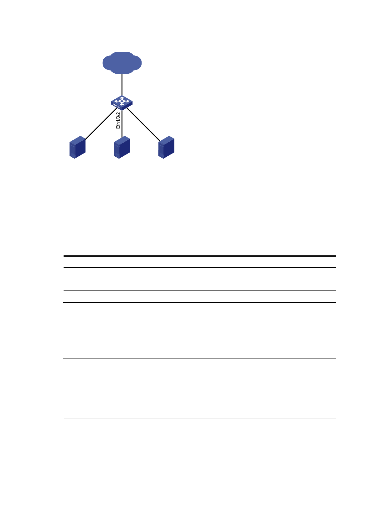
Figure 1 Speed auto negotiation application scenario
IP network
Eth1/0/4
h1/0/1
Et
Server 1 Server 2 Server 3
Switch A
Eth1
/0
/3
As shown in Figure 1, all ports on Switch A are operating in speed auto negotiation mode, with the
highest speed of 1000 Mbps. If the transmission rate of each server in the server cluster is 1000 Mbps,
their total transmission rate will exceed the capability of port Ethernet 1/0/4, the port providing access
to the Internet for the servers.
To avoid congestion on Ethernet 1/0/4, set 100 Mbps as the only option available for speed
negotiation on port Ethernet 1/0/1, Ethernet 1/0/2, and Ethernet 1/0/3. As a result, the transmission
rate on each port connected to a server is limited to 100 Mbps.
Follow these steps to set speed options for auto negotiation on an Ethernet interface:
To do… Use the command…
Remarks
Enter system view system-view —
Enter Ethernet interface view interface interface-type interface-number —
Set speed options for auto negotiation speed auto { 10 | 100 } * Optional
NOTE:
• This function is available only for Layer 2 copper ports that support speed auto negotiation, and is
unavailable for combo interfaces.
• The speed and speed auto commands supersede each other, and whichever is configured last takes
effect.
Configuring storm suppression
You can use the storm suppression function to limit the size of a particular type of traffic (broadcast,
multicast, or unknown unicast traffic) as a whole globally in system view or on a per-interface basis in
Ethernet interface view or port group view.
NOTE:
The storm suppression thresholds configured for an Ethernet interface might become invalid if you enable
the storm control function for the interface. For information about the storm control function, see
“Configuring storm control on an Ethernet interface.”
9
Page 18

In interface or port group view, you set the maximum size of broadcast, multicast or unknown unicast
traffic allowed to pass through an interface or each interface in a port group. When the broadcast,
multicast, or unknown unicast traffic on the interface exceeds this threshold, the system discards packets
until the traffic drops below this threshold.
Follow these steps to set storm suppression thresholds on one or multiple Ethernet interfaces:
To do… Use the command… Remarks
Enter system view system-view —
Use either command.
To configure storm suppression
on an Ethernet interface, enter
Ethernet interface view.
To configure storm suppression
on a group of Ethernet interfaces,
enter port group view.
Optional
By default, all broadcast traffic is
allowed to pass through.
Optional
By default, all multicast traffic is
allowed to pass through.
Optional
By default, all unknown unicast
traffic is allowed to pass through.
Enter Ethernet interface view or
port group view
Set the broadcast suppression
threshold ratio
Set the multicast suppression
threshold ratio
Set the unknown unicast
suppression threshold ratio
• Enter Ethernet interface view:
interface interface-type
interface-number
• Enter port group view:
port-group manual port-group-name
broadcast-suppression { ratio | pps
max-pps | kbps max-kbps }
multicast-suppression { ratio | pps
max-pps | kbps max-kbps }
unicast-suppression { ratio | pps
max-pps | kbps max-kbps }
NOTE:
For an Ethernet interface that belongs to a port group, if you set a traffic suppression threshold for the
interface in both Ethernet interface view and port group view, the threshold configured last takes effect.
Setting the statistics polling interval
Follow these steps to set the statistics polling interval globally or on an Ethernet interface:
To do… Use the command…
Enter system view system-view —
Enter Ethernet interface view
Set the statistics polling interval on
the Ethernet interface
To display the interface statistics collected in the last polling interval, use the display interface command.
To clear interface statistics, use the reset counters interface command.
interface interface-type
interface-number
flow-interval interval
10
Remarks
—
Optional
The default interface statistics
polling interval is 300 seconds.
Page 19
Enabling loopback detection on an Ethernet interface
A p
If a switch receives a packet that it sent, a loop has occurred to the switch. Loops might cause broadcast
storms, which degrade network performance. You can use this feature to detect whether a loop has
occurred.
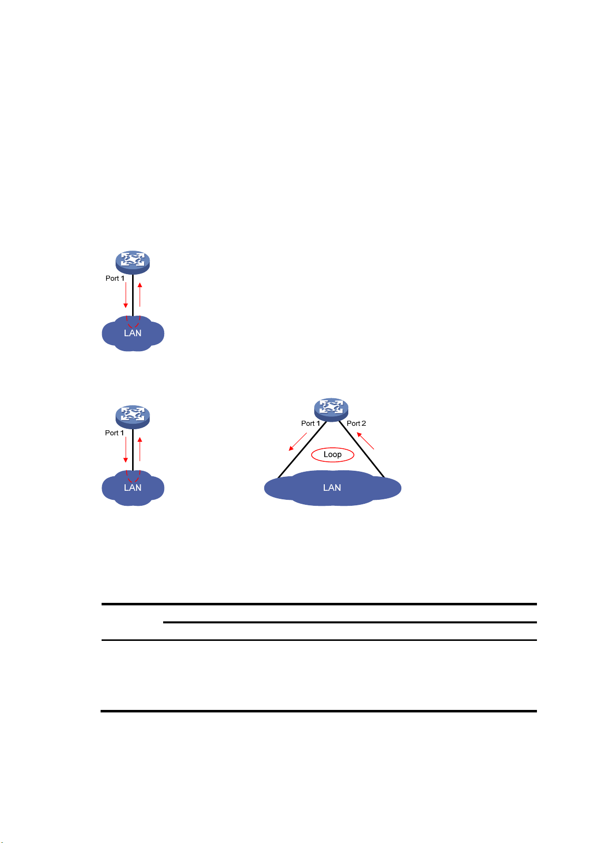
Depending on whether the receiving interface is the same as the sending interface, loops fall into the
following type: single-port loopback and multi-port loopback.
• Single-port loopback occurs when an interface receives a packet that it sent out and the receiving
interface is the same as the sending interface, as shown in Figure 2.
• Multi-por
t
loopback occurs when a switch receives a packet that it sent out but the receiving
interface might not be the sending interface, as shown in Figure 3.
Figure 2 Single-port loopback
Figure 3 Multi-port loopback
You can enable loopback detection to detect loops on an interface and, if the interface supports the
loopback-detection action command, configure the protective action to take on the receiving interface
when a loop is detected, for example, to shut down the interface. Depending on whether a protective
action is configured, the switch takes the actions in Table 1 to
Table 1 Actions to take upon detection of
a loop condition
alleviate the impact of the loop condition.
Actions
Port type
Access port
No protective action is configured
• Place the receiving interface in controlled mode.
The interface does not receive or send packets.
• Generate traps.
• Delete all MAC address entries of the interface.
11
rotective action is configured
• Perform the configured protective
action.
• Generate traps and log messages.
• Delete all MAC address entries of the
interface.
Page 20

Port type
A p
Actions
No protective action is configured
• Generate traps.
Hybrid or
trunk port
• If loopback detection control is enabled, place
the receiving interface in controlled mode. The
interface does not receive or send packets.
• Delete all MAC address entries of the interface.
Follow these steps to configure loopback detection:
rotective action is configured
• Create traps and log messages.
• If loopback detection control is
enabled, take the configured
protective action on the interface.
• Delete all MAC address entries of the
interface.
To do… Use the command…
Enter system view system-view —
Enable global loopback
detection
Enable multi-port loopback
detection
Set the loopback detection
interval
loopback-detection enable
loopback-detection
multi-port-mode enable
loopback-detection interval-time
time
• Enter Ethernet interface view
interface interface-type
Enter Ethernet interface
view or port group view
Enable loopback detection
on the interface
Enable loopback detection
control on a trunk port or a
hybrid port
interface-number
• Enter port group view
port-group manual
port-group-name
loopback-detection enable
loopback-detection control
enable
Remarks
Required
Disabled by default.
Optional
By default, multi-port loopback detection is
disabled, and the switch can only detect
single-port loopback.
Optional
30 seconds by default.
Use either command.
To configure loopback detection on one
interface, enter Ethernet interface view.
To configure loopback detection on a group
of Ethernet interfaces, enter port group view.
Required
Disabled by default.
Optional
Disabled by default.
Enable loopback detection
in all the VLANs on the
trunk or hybrid port
Set the protective action to
take on the interface when
a loop is detected
loopback-detection per-vlan
enable
loopback-detection action
{ no-learning | semi-block |
shutdown }
12
Optional
By default, a trunk or hybrid port performs
loopback detection only in its port VLAN ID
(PVID).
Optional
By default, a looped interface does not
receive or send packets; the system
generates traps and deletes all MAC
address entries of the looped interface.
With the shutdown keyword specified, the
switch shuts down the looped ports and set
their physical state to Loop down. When a
looped port recovers, you must use the undo
shutdown command to restore its forwarding
capability.
Page 21

g
NOTE:
• To use loopback detection on an Ethernet interface, you must enable the function both
the interface.
• To disable loopback detection on all interfaces, run the undo loopback-detection enable command in
system view.
• To enable a hybrid or trunk port to take the administratively specified protective action, you must use the
loopback-detection control enable command on the port.
• When you change the link t ype of an Ethernet interface by us ing the port link-type command, the switch
removes the protective action configured on the interface. For more information about the port link-type
command, see
Layer 2—LAN Switching Command Reference
.
Setting the MDI mode of an Ethernet interface
NOTE:
Fiber ports do not support the MDI mode setting.
You can use both crossover and straight-through Ethernet cables to connect copper Ethernet interfaces.
To accommodate these types of cables, a copper Ethernet interface can operate in one of the following
Medium Dependent Interface (MDI) modes:
• Across mode
• Normal mode
lobally and on
• Auto mode
A copper Ethernet interface uses an RJ-45 connector, which comprises eight pins, each of which plays a
dedicated role. For example, pins 1 and 2 transmit signals, and pins 3 and 6 receive signals. The pin
role varies by the MDI modes as follows:
• In normal mode, pins 1 and 2 are transmit pins, and pins 3 and 6 are receive pins.
• In across mode, pins 1 and 2 are receive pins, and pins 3 and 6 are transmit pins.
• In auto mode, the interface negotiates pin roles with its peer.
To enable the interface to communicate with its peer, make sure that its transmit pins are connected to the
remote receive pins. If the interface can detect the connection cable type, set the interface in auto MDI
mode. If not, set its MDI mode by using the following guidelines:
• When a straight-through cable is used, set the interface to work in the MDI mode different than its
peer.
• When a crossover cable is used, set the interface to work in the same MDI mode as its peer, or set
either end to work in auto mode.
Follow these steps to set the MDI mode of an Ethernet interface:
To do… Use the command…
Enter system view system-view —
Enter Ethernet interface view
interface interface-type
interface-number
Remarks
—
13
Page 22

To do… Use the command…
Set the MDI mode of the Ethernet
interface
mdi { across | auto | normal }
Enabling bridging on an Ethernet interface
When an incoming packet arrives, the device looks up the destination MAC address of the packet in the
MAC address table. If an entry is found, but the outgoing interface is the same as the receiving interface,
the device discards the packet.
To enable the device to forward such packets rather than drop them, enable the bridging function on the
Ethernet interface.
Follow these steps to enable bridging on an Ethernet interface:
To do… Use the command… Remarks
Enter system view system-view —
Remarks
Optional
By default, a copper Ethernet
interface operates in auto mode to
negotiate pin roles with its peer.
Enter Ethernet interface view
Enable bridging on the Ethernet
interface
interface interface-type
interface-number
port bridge enable
—
Required
Disabled by default.
Testing the cable connection of an Ethernet interface
NOTE:
• Fiber ports do not support this feature.
• If the link of an Ethernet port is up, testing its cable connection will cause the link to come down and then
go up.
You can test the cable connection of an Ethernet interface for a short or open circuit. The switch displays
cable test results within five seconds. If any fault is detected, the test results include the length of the faulty
cable segment.
Follow these steps to test the cable connection of an Ethernet interface:
To do… Use the command…
Enter system view system-view —
Remarks
Enter Ethernet interface view interface interface-type interface-number —
Test the cable connected to the
Ethernet interface
virtual-cable-test Required
14
Page 23

Configuring storm control on an Ethernet interface
A
t
t
Storm control compares broadcast, multicast, and unknown unicast traffic regularly with their respective
traffic thresholds on an Ethernet interface. For each type of traffic, storm control provides a lower
threshold and a higher threshold.
For management purposes, you can configure the interface to send threshold event traps and log
messages when monitored traffic exceeds the upper threshold or drops below the lower threshold from
the upper threshold.
When a particular type of traffic exceeds its upper threshold, the interface does either of the following,
depending on your configuration:
• Blocks this type of traffic, while forwarding other types of traffic. Even though the interface does not
forward the blocked traffic, it still counts the traffic. When the blocked traffic drops below the lower
threshold, the port begins to forward the traffic.
• Shuts down automatically. The interface shuts down automatically and stops forwarding any traffic.
When the blocked traffic drops below the lower threshold, the port does not forward the traffic. To
bring up the interface, use the undo shutdown command or disable the storm control function.
CAUTION:
lternatively, you can configure the storm suppression function to control a specific type of traffic. Do no
enable them both on an Ethernet interface at the same time because the storm suppression and storm
control functions are mutually exclusive. For example, with an unknown unicast suppression threshold se
on an Ethernet interface, do not enable storm control for unknown unicast traffic on the interface. For more
information about storm suppression, see “Configuring storm suppression.”
Follow these steps to configure storm control on an Ethernet interface:
To do… Use the command…
Enter system view system-view —
Set the traffic polling interval of the
storm control module
Enter Ethernet interface view
Enable storm control, and set the
lower and upper thresholds for
broadcast, multicast, or unknown
unicast traffic
Set the control action to take when
monitored traffic exceeds the
upper threshold
Enable the interface to send storm
control threshold event traps.
storm-constrain interval seconds
interface interface-type
interface-number
storm-constrain { broadcast |
multicast | unicast } { pps | kbps |
ratio } max-pps-values
min-pps-values
storm-constrain control { block |
shutdown }
storm-constrain enable trap
Remarks
Optional
10 seconds by default.
—
Required
Disabled by default.
Optional
Disabled by default.
Optional
By default, the interface sends
traps when monitored traffic
exceeds the upper threshold or
drops below the lower threshold
from the upper threshold.
15
Page 24

To do… Use the command…
Enable the interface to log storm
control threshold events.
storm-constrain enable log
Remarks
Optional
By default, the interface outputs log
messages when monitored traffic
exceeds the upper threshold or
drops below the lower threshold
from the upper threshold.
NOTE:
• For network stability, use the default or set a higher traffic polling interval.
• Storm control uses a complete polling cycle to collect traffic data, and analyzes the data in the next cycle.
An interface takes one to two polling intervals to take a storm control action.
• The storm control function allows you to set the upper and lower thresholds for all three types of packets
respectively on the same interface.
Setting the MTU for a Layer 3 Ethernet interface
The maximum transmission unit (MTU) affects the fragmentation and re-assembly of IP packets.
Follow these steps to set the MTU for a Layer 3 Ethernet interface:
To do… Use the command…
Enter system view system-view —
Enter Ethernet interface view interface interface-type interface-number —
Set the MTU
mtu size
Remarks
Optional
1500 bytes by default.
Displaying and maintaining an Ethernet interface
To do… Use the command…
display interface [ interface-type ] brief [ down ] [ | { begin
Display Ethernet interface
information
Display traffic statistics for the
specified interfaces
Display traffic rate statistics over
the last sampling interval
| exclude | include } regular-expression ]
display interface interface-type interface-number [ brief ]
[ | { begin | exclude | include } regular-expression ]
display counters { inbound | outbound } interface
[ interface-type ] [ | { begin | exclude | include }
regular-expression ]
display counters rate { inbound | outbound } interface
[ interface-type ] [ | { begin | exclude | include }
regular-expression ]
Remarks
Available in
any view
Available in
any view
Available in
any view
Display information about
discarded packets on the
specified interfaces
Display summary information
about discarded packets on all
interfaces
display packet-drop interface [ interface-type
[ interface-number ] ] [ | { begin | exclude | include }
regular-expression ]
display packet-drop summary [ | { begin | exclude |
include } regular-expression ]
16
Available in
any view
Available in
any view
Page 25

To do… Use the command…
Remarks
Display information about a
manual port group or all manual
port groups
Display information about the
loopback function
Display information about storm
control
Clear the interface statistics
Clear the statistics of discarded
packets on the specified
interfaces
display port-group manual [ all | name port-group-name ]
[ | { begin | exclude | include } regular-expression ]
display loopback-detection [ | { begin | exclude | include }
regular-expression ]
display storm-constrain [ broadcast | multicast | unicast ]
[ interface interface-type interface-number ] [ | { begin |
exclude | include } regular-expression ]
reset counters interface [ interface-type
[ interface-number ] ]
reset packet-drop interface [ interface-type
[ interface-number ] ]
Available in
any view
Available in
any view
Available in
any view
Available in
user view
Available in
user view
17
Page 26

Loopback and null interface configuration
Configuring a loopback interface
Introduction to the loopback interface
A loopback interface is a software-only virtual interface. It delivers the following benefits.
• The physical layer state and link-layer protocols of a loopback interface are always up unless the
loopback interface is manually shut down.
• To save IP address resources, you can assign an IP address with an all-F mask to a loopback
interface. When you assign an IPv4 address whose mask is not 32-bit, the system automatically
changes the mask into a 32-bit mask. When you assign an IPv6 address whose mask is not 128-bit,
the system automatically changes the mask into a 128-bit mask.
• You can enable routing protocols on a loopback interface, and a loopback interface can send and
receive routing protocol packets.
Because of the benefits mentioned above, loopback interfaces are widely used in the following
scenarios.
• You can configure a loopback interface address as the source address of the IP packets that the
device generates. Because loopback interface addresses are stable unicast addresses, they are
usually used as device identifications. When you configure a rule on an authentication or security
server to permit or deny packets generated by a device, you can simplify the rule by configuring it
to permit or deny packets that carry the loopback interface address identifying the device. When
you use a loopback interface address as the source address of IP packets, be sure to perform any
necessary routing configuration to make sure that the route from the loopback interface to the peer
is reachable. All data packets sent to the loopback interface are treated as packets sent to the
device itself, so the device does not forward these packets.
• Because a loopback interface is always up, it can be used in dynamic routing protocols. For
example, if you do not configure a router ID for a dynamic routing protocol, the highest loopback
interface IP address is selected as the router ID. In BGP, to prevent physical port failure from
interrupting BGP sessions, you can use a loopback interface as the source interface of BGP packets.
Configuration procedure
Follow these steps to configure a loopback interface:
To do… Use the command…
Enter system view system-view —
Remarks
Create a loopback interface and
enter loopback interface view
Set the interface description description text
interface loopback
interface-number
18
—
Optional
By default, the description of a loopback
interface is interface name Interface.
Page 27

To do… Use the command…
Shut down the loopback interface shutdown
Restore the default settings for the
loopback interface
default Optional
NOTE:
You can configure settings such as IP addresses and IP routes on loopback interfaces. For more
information, see
Layer 3—IP Services Configuration Guide
Configuring the null interface
Introduction to the null interface
A null interface is a completely software-based logical interface, and is always up. However, you cannot
use it to forward data packets or configure an IP address or link-layer protocol on it. With a null interface
specified as the next hop of a static route to a specific network segment, any packets routed to the
network segment are dropped. The null interface provides a simpler way to filter packets than ACL. You
can filter uninteresting traffic by transmitting it to a null interface instead of applying an ACL.
Remarks
Optional
By default, a loopback interface is up.
and
Layer 3—IP Routing Configuration Guide
.
For example, by executing the ip route-static 92.101.0.0 255.255.0.0 null 0 command (which configures
a static route that leads to null interface 0), you can have all the packets destined to the network segment
92.101.0.0/16 discarded.
Only one null in terface, N ull 0, is sup ported on your switch. You cannot rem ove or create a null i nterfac e.
Configuration procedure
Follow these steps to enter null interface view:
To do… Use the command…
Enter system view system-view —
Enter null interface view interface null 0
Set the interface
description
Restore the default settings
for the null interface
description text
default Optional
Remarks
Required
The Null 0 interface is the default null interface on
your switch. It cannot be manually created or
removed.
Optional
By default, the description of a null interface is
interface name Interface.
19
Page 28

Displaying and maintaining loopback and null interfaces
To do… Use the command…
display interface [ loopback ] [ brief [ down ] ] [ |
Display information about
loopback interfaces
Display information about
the null interface
Clear the statistics on a
loopback interface
Clear the statistics on the
null interface
{ begin | exclude | include } regular-expression ]
display interface loopback interface-number [ brief ]
[ | { begin | exclude | include } regular-expression ]
display interface [ null ] [ brief [ down ] ] [ | { begin |
exclude | include } regular-expression ]
display interface null 0 [ brief ] [ | { begin | exclude
| include } regular-expression ]
reset counters interface [ loopback
[ interface-number ] ]
reset counters interface [ null [ 0 ] ] Available in user view
Remarks
Available in any view
Available in any view
Available in user view
20
Page 29

MAC address table configuration
Overview
An Ethernet device uses a MAC address table for forwarding frames through unicast instead of
broadcast. This table describes from which port a MAC address (or host) can be reached. When
forwarding a frame, the device first looks up the MAC address of the frame in the MAC address table for
a match. If the switch finds an entry, it forwards the frame out of the outgoing port in the entry. If the switch
does not find an entry, it broadcasts the frame out of all but the incoming port.
How a MAC address table entry is created
The switch automatically obtains entries in the MAC address table, or you can add them manually.
MAC address learning
The device can automatically populate its MAC address table by obtaining the source MAC addresses
(called “MAC address learning”) of incoming frames on each port.
When a frame arrives at a port, Port A for example, the device performs the following tasks:
1. Verifies the source MAC address (for example, MAC-SOURCE) of the frame.
2. Looks up the source MAC address in the MAC address table.
{ If an entry is found, the device updates the entry.
{ If no entry is found, the device adds an entry for MAC-SOURCE and Port A.
3. After obtaining this source MAC address, when the device receives a frame destined for
MAC-SOURCE, the device finds the MAC-SOURCE entry in the MAC address table and forwards
the frame out Port A.
The device performs the learning process each time it receives a frame from an unknown source MAC
address, until the MAC address table is fully populated.
Manually configuring MAC address entries
With dynamic MAC address learning, a device does not distinguish between illegitimate and legitimate
frames, which can invite security hazards. For example, when a hacker sends frames with a forged
source MAC address to a port different from the one that the real MAC address is connected, the device
creates an entry for the forged MAC address, and forwards frames destined for the legal user to the
hacker instead.
To improve the port security, you can bind specific user devices to the port by manually adding MAC
address entries to the MAC address table of the switch.
Types of MAC address table entries
A MAC address table can contain the following types of entries:
• Static entries, which are manually added and never age out.
• Dynamic entries, which can be manually added or dynamically obtained and might age out.
21
Page 30

A
• Blackhole entries, which are manually configured and never age out. Blackhole entries are
configured for filtering out frames with specific source or destination MAC addresses. For example,
to block all packets destined for a specific user for security concerns, you can configure the MAC
address of this user as a blackhole MAC address entry.
To adapt to network changes and prevent inactive entries from occupying table space, an aging
mechanism is adopted for dynamic MAC address entries. Each time a dynamic MAC address entry is
obtained or created, an aging time starts. If the entry has not updated when the aging timer expires, the
device deletes the entry. If the entry has updated before the aging timer expires, the aging timer restarts.
NOTE:
static or blackhole MAC address entry can overwrite a dynamic MAC address entry, but not vice versa.
MAC address table-based frame forwarding
When forwarding a frame, the device adopts the following forwarding modes based on the MAC
address table:
• Unicast mode: If an entry is available for the destination MAC address, the device forwards the
frame out of the outgoing interface indicated by the MAC address table entry.
• Broadcast mode: If the device receives a frame with the destination address as all-ones, or no entry
is available for the destination MAC address, the device broadcasts the frame to all the interfaces
except the receiving interface.
Configuring the MAC address table
The configuration tasks discussed in the following sections are all optional and can be performed in any
order.
NOTE:
• The MAC address table can contain only Layer 2 Ethernet ports and Layer 2 aggregate interfaces.
• This document covers the configuration of unicast MAC address table entries, including static, dynamic,
and blackhole MAC address table entries. For more information about configuring static multicast MAC
address table entries for IGMP snooping and MLD snooping, see
Configuring static, dynamic, and blackhole MAC address table entries
To help prevent MAC address spoofing attacks and improve port security, you can manually add MAC
address table entries to bind ports with MAC addresses. You can also configure blackhole MAC address
entries to filter out packets with certain source or destination MAC addresses.
Adding or modifying a static, dynamic, or blackhole MAC address table entry globally
Follow these steps to add or modify a static, dynamic, or blackhole MAC address table entry in system
view:
IP Multicast Configuration Guide
.
To do… Use the command…
Enter system view system-view —
22
Remarks
Page 31

W
To do… Use the command…
Add or modify a dynamic or
static MAC address entry
Add or modify a blackhole
MAC address entry
mac-address { dynamic | static }
mac-address interface interface-type
interface-number vlan vlan-id
mac-address blackhole mac-address vlan
vlan-id
Remarks
Required
Use either command.
Make sure that you have created
the VLAN and assign the
interface to the VLAN.
Adding or modifying a static or dynamic MAC address table entry on an interface
Follow these steps to add or modify a static or dynamic MAC address table entry in interface view:
To do… Use the command…
Enter system view system-view —
Enter Layer 2 Ethernet
interface view or Layer 2
aggregate interface view
Add or modify a static or
dynamic MAC address entry
interface interface-type
interface-number
mac-address { dynamic | static }
mac-address vlan vlan-id
Remarks
—
Required
Make sure that you have created the
VLAN and assign the interface to the
VLAN.
Disabling MAC address learning on a VLAN
Sometimes, you might need to disable MAC address learning to prevent the MAC address table from
being saturated, for example, when your device is being attacked by a large amount of packets with
different source MAC addresses.
You might disable MAC address learning on a per-VLAN basis.
Follow these steps to disable MAC address learning on a VLAN:
To do… Use the command…
Enter system view system-view —
Enter VLAN view vlan vlan-id —
Disable MAC address learning on
the VLAN
mac-address mac-learning disable
Remarks
Required
Enabled by default.
NOTE:
hen MAC address learning is disabled, the learned MAC addresses remain valid until they age out.
Configuring the aging timer for dynamic MAC address entries
The MAC address table uses an aging timer for dynamic MAC address entries for security and efficient
use of table space. If a dynamic MAC address entry has failed to update before the aging timer expires,
the device deletes the entry. This aging mechanism ensures that the MAC address table can quickly
update to accommodate the latest network changes.
Set the aging timer appropriately. Too long an aging interval might cause the MAC address table to
retain outdated entries, exhaust the MAC address table resources, and fail to update its entries to
23
Page 32

ggreg
accommodate the latest network changes. Too short an interval might result in removal of valid entries,
causing unnecessary broadcasts, which might affect device performance.
Follow these steps to configure the aging timer for dynamic MAC address entries:
To do… Use the command…
Enter system view system-view —
Configure the aging timer
for dynamic MAC address
entries
mac-address timer
{ aging seconds |
no-aging }
Remarks
Optional
300 seconds by default.
The no-aging keyword disables the aging timer.
You can reduce broadcasts on a stable network by disabling the aging timer to prevent dynamic entries
from unnecessarily aging out. By reducing broadcasts, you improve not only network performance, but
also security, because you reduce the chances that a data packet will reach unintended destinations.
Configuring the MAC learning limit on ports
To prevent the MAC address table from getting too large, you can limit the number of MAC addresses
that a port can obtain.
Follow these steps to configure the MAC learning limit on a Layer 2 Ethernet interface or all ports in a port
group:
To do… Use the command…
Enter system view system-view —
Enter Layer 2 Ethernet interface
view:
Enter interface view or
port group view
interface interface-type
interface-number
Enter port group view:
port-group manual
port-group-name
Remarks
Required
Use either command.
Settings in Layer 2 Ethernet interface view
take effect on the interface only. Settings in
port group view take effect on all member
ports in the port group.
Configure the MAC
learning limit on the
interface or port group
mac-address max-mac-count count
NOTE:
• Layer 2 aggregate interfaces do not support the mac-address max-mac-count command.
• Do not configure the MAC learning limit on any member ports of an a
member ports cannot be selected.
Enabling MAC address roaming
After you enable MAC address roaming on an IRF fabric, each member switch advertises learned MAC
addresses to other member switches.
As Figure 4 sh
nnect to AP C and AP D, respectively. When Client A associates with AP C, Device A learns the MAC
co
address of Client A and advertises it to the member switch Device B.
ows, Device A and Device B form an IRF fabric enabled with MAC address roaming. They
24
Required
No MAC learning limit is configured by
default.
ation group. Otherwise, the
Page 33

Figure 4 MAC address tables of devices when Client A associates with AP C
MAC address Port
MAC A A1
Device A
Port A1
AP C
IRF
Client A
MAC address Port
MAC A A1
Device B
Port B1
AP D
If Client A roams to AP D, Device B learns the MAC address of Client A and advertises it to Device A to
ensure service continuity for Client A, as shown in Figure 5.
Figure 5 MAC address tables of devices when Client A roams to AP D
MAC address Port
MAC A A1 B1
Device A
Port A1 Port B1
AP C
IRF
Client A
MAC address Port
MAC A B1
Device B
AP D
Follow these steps to enable MAC address roaming:
To do… Use the command…
Enter system view system-view —
Remarks
Enable MAC address roaming mac-address mac-roaming enable
Required
Disabled by default.
25
Page 34

Displaying and maintaining MAC address tables
To do… Use the command…
display mac-address [ mac-address [ vlan vlan-id ] |
Display MAC address table
information
Display the aging timer for
dynamic MAC address entries
Display the system or interface
MAC address learning state
Display MAC address
statistics
[ [ dynamic | static ] [ interface interface-type
interface-number ] | blackhole ] [ vlan vlan-id ]
[ count ] ] [ | { begin | exclude | include }
regular-expression ]
display mac-address aging-time [ | { begin |
exclude | include } regular-expression ]
display mac-address mac-learning [ interface-type
interface-number ] [ | { begin | exclude | include }
regular-expression ]
display mac-address statistics [ | { begin | exclude |
include } regular-expression ]
Remarks
Available in any view
Available in any view
Available in any view
Available in any view
MAC address table configuration example
Network requirements
As shown in Figure 6:
• The MAC address of Host A is 000f-e235-dc71 and belongs to VLAN 1. It is connected to Ethernet
1/0/1 of the device. To prevent MAC address spoofing, add a static entry for the host in the MAC
address table of the device.
• The MAC address of Host B is 000f-e235-abcd and belongs to VLAN 1. For security, because this
host once behaved suspiciously on the network, add a blackhole MAC address entry for the host
MAC address, so that all packets destined for the host will be dropped.
• Set the aging timer for dynamic MAC address entries to 500 seconds.
Figure 6 Network diagram
Configuration procedure
# Add a static MAC address entry.
<Sysname> system-view
[Sysname] mac-address static 000f-e235-dc71 interface ethernet 1/0/1 vlan 1
26
Page 35

# Add a blackhole MAC address entry.
[Sysname] mac-address blackhole 000f-e235-abcd vlan 1
# Set the aging timer for dynamic MAC address entries to 500 seconds.
[Sysname] mac-address timer aging 500
# Display the MAC address entry for port Ethernet 1/0/1.
[Sysname] display mac-address interface ethernet 1/0/1
MAC ADDR VLAN ID STATE PORT INDEX AGING TIME(s)
000f-e235-dc71 1 Config static Ethernet 1/0/1 NOAGED
--- 1 mac address(es) found ---
# Display information about the blackhole MAC address table.
[Sysname] display mac-address blackhole
MAC ADDR VLAN ID STATE PORT INDEX AGING TIME(s)
000f-e235-abcd 1 Blackhole N/A NOAGED
--- 1 mac address(es) found ---
# View the aging time of dynamic MAC address entries.
[Sysname] display mac-address aging-time
Mac address aging time: 500s
27
Page 36

MAC Information configuration
Overview
Introduction to MAC Information
To monitor a network, you must monitor users who are joining and leaving the network. Because a MAC
address uniquely identifies a network user, you can monitor users who are joining and leaving a network
by monitoring their MAC addresses.
With the MAC Information function, Layer 2 Ethernet ports send Syslog or trap messages to the monitor
end in the network when they obtain or delete MAC addresses. By analyzing these messages, the
monitor end can monitor users who are accessing the network.
How MAC Information works
When a new MAC address is obtained or an existing MAC address is deleted on a device, the device
writes related information about the MAC address to the buffer area used to store user information.
When the timer set for sending MAC address monitoring Syslog or trap messages expires, or when the
buffer reaches capacity, the device sends the Syslog or trap messages to the monitor end.
The device writes information and sends messages only for the following MAC addresses: automatically
learned source MAC addresses, MAC addresses that pass or fail MAC authentication, MAC addresses
that pass 802.1X authentication, MAC addresses matching OUI addresses in the voice VLAN feature,
and secure MAC addresses. The device does not write information or send messages for blackhole MAC
address, static MAC addresses, dynamic MAC addresses that are manually configured, multicast MAC
addresses, and local MAC addresses.
For more information about MAC authentication, 802.1X, and secure MAC addresses in port security,
see Security Configuration Guide. For more information about voice VLAN and OUI addresses, see the
chapter “Voice VLAN configuration.”
Configuring MAC Information
Enabling MAC Information globally
Follow these steps to enable MAC Information globally:
To do… Use the command…
Enter system view system-view —
Enable MAC Information globally mac-address information enable
Remarks
Required
Disabled by default.
Enabling MAC Information on an interface
Follow these steps to enable MAC Information on an interface:
28
Page 37

To do… Use the command…
Enter system view system-view —
Enter Layer 2 Ethernet interface
view
Enable MAC Information on the
interface
interface interface-type
interface-number
mac-address information enable
{ added | deleted }
NOTE:
To enable MAC Information on an Ethernet port, enable MAC Information globally first.
Configuring MAC Information mode
Follow these steps to configure MAC Information mode:
To do… Use the command…
Enter system view system-view —
Configure MAC Information mode
mac-address information mode
{ syslog | trap }
Remarks
—
Required
Disabled by default.
Remarks
Optional
trap by default.
Configuring the interval for sending Syslog or trap messages
To prevent Syslog or trap messages from being sent too frequently, you can set the interval for sending
Syslog or trap messages.
Follow these steps to set the interval for sending Syslog or trap messages:
To do… Use the command…
Enter system view system-view —
Set the interval for sending Syslog
or trap messages
mac-address information interval
interval-time
Remarks
Optional
One second by default.
Configuring the MAC Information queue length
To avoid losing user MAC address information, when the buffer that stores user MAC address
information reaches capacity, the user MAC address information in the buffer is sent to the monitor end
in the network, even if the timer set for sending MAC address monitoring Syslog or trap messages has not
expired yet.
Follow these steps to configure the MAC Information queue length:
To do… Use the command…
Enter system view system-view —
Remarks
Configure the MAC Information
queue length
mac-address information
queue-length value
29
Optional
50 by default.
Page 38

MAC Information configuration example
Network requirements
As shown in Figure 7:
• Host A is connected to a remote server (Server) through Device.
• Enable MAC Information on Ethernet 1/0/1 on Device. Device sends MAC address changes in
Syslog messages to Host B through Ethernet 1/0/3. Host B analyzes and displays the Syslog
messages.
Figure 7 Network diagram
Configuration procedure
1. Configure Device to send Syslog messages to Host B.
For more information, see Network Management and Monitoring Configuration Guide.
2. Enable MAC Information.
# Enable MAC Information on Device.
<Device> system-view
[Device] mac-address information enable
# Configure MAC Information mode as Syslog.
[Device] mac-address information mode syslog
# Enable MAC Information on Ethernet 1/0/1.
[Device] interface ethernet 1/0/1
[Device-Ethernet1/0/1] mac-address information enable added
[Device-Ethernet1/0/1] mac-address information enable deleted
[Device-Ethernet1/0/1] quit
# Set the MAC Information queue length to 100.
[Device] mac-address information queue-length 100
# Set the interval for sending Syslog or trap messages to 20 seconds.
[Device] mac-address information interval 20
30
Page 39

r
Ethernet link aggregation configuration
Overview
Ethernet link aggregation, or simply link aggregation, combines multiple physical Ethernet ports into one
logical link, called an “aggregate link”. Link aggregation delivers the following benefits:
• Increases bandwidth beyond the limits of any single link. In an aggregate link, traffic is distributed
across the member ports.
• Improves link reliability. The member ports dynamically back up one another. When a member port
fails, its traffic is automatically switched to other member ports.
As shown in Figure 8, Device A and Device B are connected by three physical Ethernet links. These
ph
ysical Ethernet links are combined into an aggregate link, Link Aggregation 1. The bandwidth of this
aggregate link is as high as the total bandwidth of the three physical Ethernet links. At the same time, the
three Ethernet links back up one another.
Figure 8 Ethernet link aggregation
Basic concepts
Aggregation group, member port, aggregate interface
Link aggregation is implemented through link aggregation groups. An aggregation group is a group of
Ethernet interfaces combined together, which are called “member ports” of the aggregation group. For
each aggregation group, a logical interface, called an “aggregate interface”, is created. To an upper
layer entity that uses the link aggregation service, a link aggregation group appears to be a single
logical link and data traffic is transmitted through the aggregate interface.
Aggregate interfaces have the following types: bridge-aggregation (BAGG) interfaces, also called Layer
2 aggregate interfaces, and route-aggregation (RAGG) interfaces, also called Layer 3 aggregate
interfaces. When you create an aggregate interface, the switch automatically creates an aggregation
group of the same type and number as the aggregate interface. For example, when you create interface
Bridge-Aggregation 1, Layer 2 aggregation group 1 is created.
You can assign Layer 2 Ethernet interfaces only to a Layer 2 aggregation group, and Layer 3 Ethernet
interfaces only to a Layer 3 aggregation group.
NOTE:
The rate of an aggregate interface equals the total rate of its member ports in the Selected state, and its
duplex mode is the same as the selected member ports. For more information about the states of membe
ports in an aggregation group, see “Aggregation states of member ports in an aggregation group.”
Aggregation states of member ports in an aggregation group
A member port in an aggregation group can be in either of the following aggregation states:
31
Page 40

• Selected: A Selected port can forward user traffic.
• Unselected: An Unselected port cannot forward user traffic.
Operational key
When aggregating ports, the system automatically assigns each port an operational key based on port
information such as port rate and duplex mode. Any change to this information triggers a recalculation
of the operational key.
In an aggregation group, all selected member ports are assigned the same operational key.
Configuration classes
Every configuration setting on a port might affect its aggregation state. Port configurations fall into the
following classes:
• Port attribute configurations, including port rate, duplex mode, and link status (up/down). These
are the most basic port configurations.
• Class-two configurations. A member port can be placed in the Selected state only if it has the same
class-two configurations as the aggregate interface.
Table 2 Class-two configurations
Feature Considerations
Port isolation
QinQ
VLAN
MAC address learning
Whether the port has joined an isolation group
QinQ enable state (enable/disable), TPID for VLAN tags, outer VLAN tags to be
added, inner-to-outer VLAN priority mappings, inner-to-outer VLAN tag
mappings, inner VLAN ID substitution mappings
Permitted VLAN IDs, PVID, link type (trunk, hybrid, or access), IP subnet-based
VLAN configuration, protocol-based VLAN configuration, VLAN tagging mode
MAC address learning capability, MAC address learning limit, forwarding of
frames with unknown destination MAC addresses after the MAC address
learning limit is reached
NOTE:
• Class-two configurations made on an aggregate interface are automatically synchronized to all
member ports of the interface. These configurations are retained on the member ports even after the
aggregate interface is removed.
• Any class-two configuration change might affect the aggregation state of link aggregation member
ports and ongoing traffic. To be sure that you are aware of the risk, the system displays a warning
message every time you attempt to change a class-two configuration setting on a member port.
• Class-one configurations do not affect the aggregation state of the member port even if they are
different from those on the aggregate interface. GVRP and MSTP settings are examples of class-one
configurations.
NOTE:
The class-one configuration for a member port is effective only when the member port leaves the
aggregation group.
32
Page 41

gory
yp
Reference port
When setting the aggregation state of the ports in an aggregation group, the system automatically picks
a member port as the reference port. A Selected port must have the same port attributes and class-two
configurations as the reference port.
LACP
The IEEE 802.3ad Link Aggregation Control Protocol (LACP) enables dynamic aggregation of physical
links. It uses link aggregation control protocol data units (LACPDUs) for exchanging aggregation
information between LACP-enabled devices.
1. LACP functions
The IEEE 802.3ad LACP offers basic LACP functions and extended LACP functions, as described in Table
3.
Table 3 Basic and ext
Cate
Basic LACP
functions
Extended LACP
functions
Description
e
nded LACP functions
Implemented through the basic LACPDU fields, including the system LACP priority, system
MAC address, port aggregation priority, port number, and operational key.
Each member port in a LACP-enabled aggregation group exchanges the preceding
information with its peer. When a member port receives an LACPDU, it compares the
received information with the information received on the other member ports. In this way,
the two systems reach an agreement on which ports should be placed in the Selected state.
Implemented by extending the LACPDU with new Type/Length/Value (TLV) fields. This is
how the LACP multi-active detection (MAD) mechanism of the Intelligent Resilient Framework
(IRF) feature is implemented. The 3600 v2 Switch Series can participate in LACP MAD as
either an IRF member switch or an intermediate device.
NOTE:
For more information about IRF, member switches, intermediate devices, and the LACP MAD mechanism,
IRF Configuration Guide
see
2. LACP priorities
.
LACP priorities have the following types: system LACP priority and port aggregation priority.
Table 4 LACP priorities
T
e Description Remarks
Used by two peer devices (or systems) to determine which one is
System LACP
priority
Port aggregation
priority
3. LACP timeout interval
superior in link aggregation.
In dynamic link aggregation, the system that has higher system LACP
priority sets the Selected state of member ports on its side first, and then
the system that has lower priority sets the port state accordingly.
Determines the likelihood of a member port to be selected on a system.
The higher the port aggregation priority, the higher the likelihood.
The smaller the
priority value,
the higher the
priority.
The LACP timeout interval specifies how long a member port waits to receive LACPDUs from the peer port.
If a local member port fails to receive LACPDUs from the peer within three times the LACP timeout interval,
33
Page 42

p
the member port assumes that the peer port has failed. You can configure the LACP timeout interval as
either the short timeout interval (1 second) or the long timeout interval (30 seconds).
Link aggregation modes
Link aggregation has the following modes: dynamic and static. Dynamic link aggregation uses LACP
and static link aggregation does not. Table 5 compares the two aggregation modes.
Table 5 A comparison
Aggregation
mode
Static Disabled
Dynamic Enabled
between static and dynamic aggregation modes
LACP status on
member
orts
Pros Cons
Aggregation is stable. Peers do
not affect the aggregation state of
the member ports.
The administrator does not need to
maintain link aggregations. The
peer systems maintain the
aggregation state of the member
ports automatically.
The following points apply to a dynamic link aggregation group:
• A Selected port can receive and send LACPDUs.
• An Unselected port can receive and send LACPDUs only if it is up and has the same class-two
configurations as the aggregate interface.
Aggregating links in static mode
The member ports do not adjust the
aggregation state according to
that of the peer ports. The
administrator must manually
maintain link aggregations.
Aggregation is unstable. The
aggregation state of the member
ports is susceptible to network
changes.
LACP is disabled on the member ports in a static aggregation group. You must manually maintain the
aggregation state of the member ports.
The static link aggregation process comprises:
• Selecting a reference port
• Setting the aggregation state of each member port
Selecting a reference port
The system selects a reference port from the member ports that are:
• Are in the up state and have
• Have the same class-two configurations as the aggregate interface.
The candidate ports are sorted by aggregation priority, duplex, and speed in the following order:
• Lowest aggregation priority value
• Full duplex/high speed
• Full duplex/low speed
• Half duplex/high speed
• Half duplex/low speed
The one at the top is selected as the reference port. If two ports have the same aggregation priority,
duplex mode, and speed, the one with the lower port number wins.
34
Page 43

Setting the aggregation state of each member port
After selecting the reference port, the static aggregation group sets the aggregation state of each
member port.
Figure 9 Setting the aggregation state of a member port in a static aggregation group
NOTE:
• To ensure stable aggregation state and service continuity, do not change port attributes or class-two
configurations on any member port.
• If a static aggregation group has reached the limit on Selected ports, any port that joins the group is
placed in the Unselected state to avoid traffic interruption on the current Selected ports. Avoid this
situation, however, because it might cause the aggregation state of a port to change after a reboot.
Aggregating links in dynamic mode
LACP is automatically enabled on all member ports in a dynamic aggregation group. The protocol
automatically maintains the aggregation state of ports.
The dynamic link aggregation process comprises:
• Selecting a reference port
• Setting the aggregation state of each member port
Selecting a reference port
The local system (the actor) and the remote system (the partner) negotiate a reference port using the
following workflow:
35
Page 44

1. The systems compare the system ID (which comprises the system LACP priority and the system
MAC address). The system with the lower LACP priority value wins. If they are the same, the
systems compare the system MAC addresses. The system with the lower MAC address wins.
2. The system with the smaller system ID selects the port with the smallest port ID as the reference port.
A port ID comprises a port aggregation priority and a port number. The port with the lower
aggregation priority value wins. If two ports have the same aggregation priority, the system
compares their port numbers. The port with the smaller port number wins.
Setting the aggregation state of each member port
After the reference port is selected, the system with the lower system ID sets the state of each member port
in the dynamic aggregation group on its side.
Figure 10 Setting the state of a member port in a dynamic aggregation group
Meanwhile, the system with the higher system ID, which has identified the aggregation state changes on
the remote system, sets the aggregation state of local member ports as the same as their peer ports.
36
Page 45

ggreg
NOTE:
• A dynamic link aggregation group preferably sets full-duplex ports as the Selected ports, and will set
one, and only one, half-duplex port as a Selected port when none of the full-duplex ports can be
selected or only half-duplex ports exist in the group.
• To ensure stable aggregation state and service continuity, do not change port attributes or class-two
configurations on any member port.
• In a dynamic a
ation group, when the aggregation state of a local port changes, the aggregation
state of the peer port changes.
• A port that joins a dynamic aggregation group after the Selected port limit has been reached is placed
in the Selected state if it is more eligible for being selected than a current member port.
Load-sharing criteria for link aggregation groups
In a link aggregation group, traffic can be load-shared across the selected member ports based on a set
of criteria, depending on your configuration.
You can choose one of the following criteria or any combination for load sharing:
• MAC addresses
• Service port numbers
• Ingress ports
• IP addresses
• IP protocols
Alternatively, you can let the system automatically choose link-aggregation load-sharing criteria based
on packet types (Layer 2, IPv4, or IPv6 for example) or configure the system to perform per-packet load
sharing.
Ethernet link aggregation configuration task list
Complete the following tasks to configure Ethernet link aggregation:
Task Remarks
Configuring an
aggregation group
Configuring an
aggregate interface
Configuring a static aggregation group
Configuring a dynamic aggregation group
Configuring the description of an aggregate i
Configuring the MTU of a Layer 3 aggregate interface Optional
Enabling link state traps for an aggregate interface Optional
Setting the minimum number of Selected ports for an
aggregation group
Shutting down an aggregate interface Optional
Restoring the default settings for an aggregate interface Optional
37
nterface Optional
Select either task
Optional
Page 46

yp
Task Remarks
Configuring load
sharing for link
aggregation groups
Enabling link-aggregation traffic redirection Optional
Configuring load-sharing criteria for link aggregation groups Optional
Enabling local-first load sharing for link aggregation Optional
Configuring an aggregation group
You can choose to create a Layer 2 or Layer 3 link aggregation group depending on the ports to be
aggregated:
• To aggregate Layer 2 Ethernet interfaces, create a Layer 2 link aggregation group.
• To aggregate Layer 3 Ethernet interfaces, create a Layer 3 link aggregation group.
Configuration guidelines
You cannot assign a port to a Layer 2 aggregation group if any of the features listed in Table 6 is
configured on the port.
Table 6 Features incompatible with Layer 2 aggregation groups
Feature Reference
RRPP RRPP in High Availability Configuration Guide
MAC authentication
Port security Port security in Security Configuration Guide
IP source guard IP source guard in Security Configuration Guide
802.1X 802.1X in Security Configuration Guide
Ports specified as source interfaces
in portal-free rules
MAC authentication in Security Configuration Guide
Portal in Security Configuration Guide
You cannot assign a port to a Layer 3 aggregation group if any of the features listed in Table 7 is
configured on the port.
Table 7 Interfaces that cannot be assigned to a Layer 3 aggregation group
Interface t
Interfaces configured with IP addresses IP addressing in Layer 3—IP Services Configuration Guide
Interfaces configured as DHCP/BOOTP
clients
VRRP VRRP in High Availability Configuration Guide
Portal Portal in Security Configuration Guide
e Reference
DHCP in Layer 3—IP Services Configuration Guide
38
Page 47

ggreg
g aggreg
NOTE:
• If a port is used as a reflector port for port mirroring, do not assign it to an a
information about reflector ports, see Network Management and Monitoring Configuration Guide.
• You can assign the following ports to an aggregation group: monitor ports for port mirroring, ports
configured with static MAC addresses, or ports configured with MAC address learning limit.
CAUTION:
Removing an aggregate interface also removes the correspondin
all member ports leave the aggregation group.
Configuring a static aggregation group
NOTE:
To guarantee a successful static aggregation, make sure that the ports at both ends of each link are in the
same aggregation state.
Configuring a Layer 2 static aggregation group
Follow these steps to configure a Layer 2 static aggregation group:
To do... Use the command...
Enter system view
system-view —
Remarks
ation group. For more
ation group. At the same time,
Create a Layer 2 aggregate
interface and enter Layer 2
aggregate interface view
Exit to system view
Enter Layer 2 Ethernet
interface view
Assign the Ethernet interface
to the aggregation group
Assign the port an
aggregation priority
interface
bridge-aggregation
interface-number
quit —
interface interface-type
interface-number
port link-aggregation
group number
link-aggregation
port-priority port-priority
Configuring a Layer 3 static aggregation group
Follow these steps to configure a Layer 3 static aggregation group:
To do... Use the command... Remarks
Enter system view
system-view —
Required
When you create a Layer 2 aggregate interface,
the system automatically creates a Layer 2 static
aggregation group numbered the same.
Required
Repeat these two steps to assign more Layer 2
Ethernet interfaces to the aggregation group.
Optional
By default, the aggregation priority of a port is
32768.
Changing the aggregation priority of a port might
affect the aggregation state of the ports in the
static aggregation group.
39
Page 48

ggreg
To do... Use the command... Remarks
Create a Layer 3 aggregate
interface and enter Layer 3
aggregate interface view
Exit to system view
Enter Layer 3 Ethernet
interface view
Assign the Ethernet interface
to the aggregation group
Assign the port an
aggregation priority
interface
route-aggregation
interface-number
quit —
interface interface-type
interface-number
port link-aggregation
group number
link-aggregation
port-priority port-priority
Required
When you create a Layer 3 aggregate interface,
the system automatically creates a Layer 3 static
aggregation group numbered the same.
Required
Repeat these two steps to assign more Layer 3
Ethernet interfaces to the aggregation group.
Optional
By default, the aggregation priority of a port is
32768.
Changing the aggregation priority of a port might
affect the aggregation state of the ports in the
static aggregation group.
Configuring a dynamic aggregation group
NOTE:
To guarantee a successful dynamic aggregation, be sure that the peer ports of the ports a
end are also aggregated. The two ends can automatically negotiate the aggregation state of each member
port.
Configuring a Layer 2 dynamic aggregation group
Follow these steps to configure a Layer 2 dynamic aggregation group:
To do... Use the command... Remarks
Enter system view
Set the system LACP
priority
Create a Layer 2
aggregate interface and
enter Layer 2 aggregate
interface view
Configure the
aggregation group to
work in dynamic
aggregation mode
system-view —
lacp system-priority
system-priority
interface
bridge-aggregation
interface-number
link-aggregation mode
dynamic
ated at one
Optional
By default, the system LACP priority is 32768.
Changing the system LACP priority might affect the
aggregation state of the ports in a dynamic aggregation
group.
Required
When you create a Layer 2 aggregate interface, the
system automatically creates a Layer 2 static
aggregation group numbered the same.
Required
By default, an aggregation group works in static
aggregation mode.
Exit to system view
quit —
40
Page 49

To do... Use the command... Remarks
Enter Layer 2 Ethernet
interface view
Assign the Ethernet
interface to the
aggregation group
Assign the port an
aggregation priority
Set the LACP timeout
interval on the port to
the short timeout interval
(1 second)
interface interface-type
interface-number
port link-aggregation
group number
link-aggregation
port-priority port-priority
lacp period short
Configuring a Layer 3 dynamic aggregation group
Follow these steps to configure a Layer 3 dynamic aggregation group:
To do... Use the command... Remarks
Enter system view
Set the system LACP
priority
system-view —
lacp system-priority
system-priority
Required
Repeat these two steps to assign more Layer 2 Ethernet
interfaces to the aggregation group.
Optional
By default, the aggregation priority of a port is 32768.
Changing the aggregation priority of a port might affect
the aggregation state of the ports in the dynamic
aggregation group.
Optional
By default, the LACP timeout interval on a port is the
long timeout interval (30 seconds).
Optional
By default, the system LACP priority is 32768.
Changing the system LACP priority might affect
the aggregation state of the ports in the
dynamic aggregation group.
Create a Layer 3
aggregate interface and
enter Layer 3 aggregate
interface view
Configure the aggregation
group to work in dynamic
aggregation mode
Exit to system view
Enter Layer 3 Ethernet
interface view
Assign the Ethernet
interface to the
aggregation group
Assign the port an
aggregation priority
Required
interface route-aggregation
interface-number
link-aggregation mode
dynamic
quit —
interface interface-type
interface-number
port link-aggregation group
number
link-aggregation port-priority
port-priority
When you create a Layer 3 aggregate
interface, the system automatically creates a
Layer 3 static aggregation group numbered the
same.
Required
By default, an aggregation group works in
static aggregation mode.
Required
Repeat these two steps to assign more Layer 3
Ethernet interfaces to the aggregation group.
Optional
By default, the aggregation priority of a port is
32768.
Changing the aggregation priority of a port
might affect the aggregation state of ports in the
dynamic aggregation group.
41
Page 50

To do... Use the command... Remarks
Set the LACP timeout
interval on the port to the
short timeout interval (1
second)
lacp period short
Optional
By default, the LACP timeout interval on a port is
the long timeout interval (30 seconds).
Configuring an aggregate interface
NOTE:
Most of the configurations that can be performed on Layer 2 or Layer 3 Ethernet interfaces can also be
performed on Layer 2 or Layer 3 aggregate interfaces.
Configuring the description of an aggregate interface
You can configure the description of an aggregate interface for administration purposes such as
describing the purpose of the interface.
Follow these steps to configure the description of an aggregate interface:
To do... Use the command... Remarks
Enter system view
system-view —
Enter Layer 2
Enter
aggregat
e interface
view
Configure the description of the
aggregate interface
aggregate
interface view
Enter Layer 3
aggregate
interface view
interface bridge-aggregation
interface-number
interface route-aggregation
interface-number
description text
Required
Use either command.
Optional
By default, the description of an
interface is in the format of
interface-name Interface, such as
Bridge-Aggregation1 Interface.
Configuring the MTU of a Layer 3 aggregate interface
Maximum transmission unit (MTU) of an interface affects IP packets fragmentation and reassembly on the
interface.
Follow these steps to change the MTU of a Layer 3 aggregate interface:
To do... Use the command... Remarks
Enter system view
Enter Layer 3 aggregate interface view
system-view —
interface route-aggregation
interface-number
—
Configure the MTU of the Layer 3
aggregate interface
mtu size
42
Optional
1500 bytes by default.
Page 51

Enabling link state traps for an aggregate interface
You can configure an aggregate interface to generate linkUp trap messages when its link goes up and
linkDown trap messages when its link goes down. For more information, see Network Management and
Monitoring Configuration Guide.
Follow these steps to enable link state traps on an aggregate interface:
To do... Use the command... Remarks
Enter system view
Enable the trap function globally
Enter
aggregat
e interface
view
Enable link state traps for the
aggregate interface
Enter Layer 2
aggregate interface
view
Enter Layer 3
aggregate interface
system-view —
Optional
snmp-agent trap enable [ standard
[ linkdown | linkup ] * ]
interface bridge-aggregation
interface-number
interface route-aggregation
interface-number
enable snmp trap updown
By default, link state trapping is
enabled globally and on all
interfaces.
Required
Use either command.
Optional
Enabled by default.
Setting the minimum number of Selected ports for an aggregation group
The bandwidth of an aggregate link increases along with the number of selected member ports. To avoid
congestion caused by insufficient Selected ports on an aggregate link, you can set the minimum number
of Selected ports required for bringing up the specific aggregate interface.
This minimum threshold setting affects the aggregation state of both aggregation member ports and the
aggregate interface in the following ways:
• All member ports change to the Unselected state and the link of the aggregate interface goes down,
when the number of member ports eligible for being selected is smaller than the minimum
threshold.
• When the minimum threshold is reached, the eligible member ports change to the Selected state,
and the link of the aggregate interface goes up.
Follow these steps to set the minimum number of Selected ports for an aggregation group:
To do... Use the command...
Enter system view system-view —
Enter
aggregate
interface
view
Set the minimum number of Selected ports
for the aggregation group
Enter Layer 2 aggregate
interface view
Enter Layer 3 aggregate
interface view
interface bridge-aggregation
interface-number
interface route-aggregation
interface-number
link-aggregation selected-port
minimum number
43
Remarks
Required
Use either command.
Required
Not specified by default.
Page 52

ggreg
ght
CAUTION:
• If you set this minimum threshold for a static a
ation group, you must also make the same setting for
its peer aggregation group to guarantee correct aggregation.
• Configuring the minimum number of Selected ports required to bring up an aggregation group mi
cause all the member ports in the aggregation group to become unselected.
Shutting down an aggregate interface
Shutting down or bringing up an aggregate interface affects the aggregation state and link state of ports
in the corresponding aggregation group in the following ways:
• When an aggregate interface is shut down, all Selected ports in the corresponding aggregation
group become unselected and their link state becomes down.
• When an aggregate interface is brought up, the aggregation state of ports in the corresponding
aggregation group is recalculated and their link state becomes up.
Follow these steps to shut down an aggregate interface:
To do... Use the command... Remarks
Enter system view
Enter
aggregate
interface
view
Shut down the aggregate interface shutdown
Enter Layer 2
aggregate interface
view
Enter Layer 3
aggregate interface
view
system-view —
interface bridge-aggregation
interface-number
interface route-aggregation
interface-number
Required
Use either command.
Required
By default, aggregate interfaces
are up.
Restoring the default settings for an aggregate interface
Follow these steps to restore the default settings for an aggregate interface:
To do... Use the command... Remarks
Enter system view
Enter
aggregate
interface
view
Enter Layer 2 aggregate
interface view
Enter Layer 3 aggregate
interface view
system-view —
interface bridge-aggregation
interface-number
interface route-aggregation
interface-number
Required
Use either command.
Restore the default settings for the
aggregate interface
default Required
44
Page 53

Configuring load sharing for link aggregation groups
Configuring load-sharing criteria for link aggregation groups
You can determine how traffic is load-shared in a link aggregation group by configuring load-sharing
criteria. The criteria can be MAC addresses, service port numbers, ingress ports, or IP addresses carried
in packets, or any combination. You can also let the system automatically choose link-aggregation
load-sharing criteria based on packet types (Layer 2, IPv4, or IPv6, for example) or perform per-packet
load sharing.
You can configure global or group-specific load-sharing criteria. A link aggregation group preferentially
uses the group-specific load-sharing criteria. If no group-specific load-sharing criteria are available, the
group uses the global load-sharing criteria.
Configuring the global link-aggregation load-sharing criteria
Follow these steps to configure the global link-aggregation load-sharing criteria:
To do... Use the command... Remarks
Enter system view
Configure the global
link-aggregation
load-sharing criteria
system-view —
link-aggregation load-sharing
mode { { destination-ip |
destination-mac | destination-port
| ingress-port | source-ip |
source-mac | source-port } *
In system view, the switch supports the following load-sharing criteria and combinations:
• Source IP address
• Destination IP address
• Source MAC address
• Destination MAC address
• Source IP address and destination IP address
• Source IP address and source port
• Destination IP address and destination port
• Any combination of incoming port, source MAC address, and destination MAC address
Configuring group-specific load-sharing criteria
Follow these steps to configure load-sharing criteria for a link aggregation group:
Required
By default, The load is shared by packet type.
To do… Use the command…
Enter system view system-view —
Enter Layer 2
Enter
aggregate
interface
view
aggregate
interface view
Enter Layer 3
aggregate
interface view
interface bridge-aggregation
interface-number
interface route-aggregation
interface-number
45
Remarks
Required
Use either command.
Page 54

To do… Use the command…
Configure the load-sharing
criteria for the aggregation
group
link-aggregation load-sharing mode
{ { destination-ip | destination-mac |
source-ip | source-mac } * }
Remarks
Required
The default load-sharing criteria are
the same as the global load-sharing
criteria.
In Layer 2 aggregate interface view, the switch supports the following load-sharing criteria and
combinations:
• Automatic load-sharing criteria determined based on the packet type
• Source IP address
• Destination IP address
• Source MAC address
• Destination MAC address
• Destination IP address and source IP address
• Destination MAC address and source MAC address
Enabling local-first load sharing for link aggregation
Use the local-first load sharing mechanism in a cross-switch link aggregation scenario to distribute traffic
preferentially across member ports on the ingress switch rather than all member ports.
When you aggregate ports on different member switches in an IRF fabric, you can use local-first load
sharing to reduce traffic on IRF links, as shown in Figure 11. F
or more information about IRF, see IR
F
Configuration Guide.
Figure 11 Local-first link-aggregation load sharing
Follow these steps to enable local-first load sharing for link aggregation:
To do... Use the command... Remarks
Enter system view
system-view —
46
Page 55

ggreg
To do... Use the command... Remarks
Enable local-first load-sharing for
link aggregation
link-aggregation load-sharing
mode local-first
Optional
Enabled by default.
Enabling link-aggregation traffic redirection
The link-aggregation traffic redirection function can redirect traffic between IRF member switches for a
cross-device link aggregation group. Link-aggregation traffic redirection prevents traffic interruption when
you reboot an IRF member switch that contains link aggregation member ports. For more information
about IRF, see IRF Configuration Guide.
Follow these steps to enable link-aggregation traffic redirection:
To do... Use the command... Remarks
Enter system view
Enable link-aggregation traffic
redirection
CAUTION:
• Link-aggregation traffic redirection applies only to dynamic link aggregation groups and only to known
unicast packets.
system-view —
link-aggregation lacp
traffic-redirect-notification enable
Optional
Disabled by default.
• To prevent traffic interruption, enable link-a
ation traffic redirection on devices at both ends of the
aggregate link.
• To prevent packet loss that might occur at a reboot, disable both MSTP and link-aggregation traffic
redirection.
Displaying and maintaining Ethernet link aggregation
To do... Use the command... Remarks
display interface [ bridge-aggregation |
Display information for an
aggregate interface or multiple
aggregate interfaces
Display the local system ID
Display the global or
group-specific link-aggregation
load-sharing criteria
route-aggregation ] [ brief [ down ] ] [ | { begin
| exclude | include } regular-expression ]
display interface { bridge-aggregation |
route-aggregation } interface-number [ brief ] [ |
{ begin | exclude | include } regular-expression ]
display lacp system-id [ | { begin | exclude |
include } regular-expression ]
display link-aggregation load-sharing mode
[ interface [ { bridge-aggregation |
route-aggregation } interface-number ] ] [ |
{ begin | exclude | include } regular-expression ]
Available in any view
Available in any view
Available in any view
Display detailed link aggregation
information for link aggregation
member ports
display link-aggregation member-port
[ interface-list ] [ | { begin | exclude | include }
regular-expression ]
47
Available in any view
Page 56

g
To do... Use the command... Remarks
Display summary information
about all aggregation groups
Display detailed information about
a specific or all aggregation
groups
Clear LACP statistics for a specific
or all link aggregation member
ports
Clear statistics for a specific or all
aggregate interfaces
display link-aggregation summary [ | { begin |
exclude | include } regular-expression ]
display link-aggregation verbose
[ { bridge-aggregation | route-aggregation }
[ interface-number ] ] [ | { begin | exclude |
include } regular-expression ]
reset lacp statistics [ interface interface-list ]
reset counters interface [ { bridge-aggregation |
route-aggregation } [ interface-number ] ]
Available in any view
Available in any view
Available in user
view
Available in user
view
Ethernet link aggregation configuration examples
NOTE:
In an aggregation group, only ports that have the same port attributes and class-two configurations (see
“Configuration classes”) as the reference port (see “Refer
sure that all member ports have the same port attributes and class-two configurations as the reference
port. The other settin
s only need to be configured on the aggregate interface, not on the member ports.
ence port”) can operate as Selected ports. Make
Layer 2 static aggregation configuration example
Network requirements
As shown in Figure 12:
• Device A and Device B are connected through their respective Layer 2 Ethernet interfaces Ethernet
1/0/1 through Ethernet 1/0/3.
• Configure a Layer 2 static aggregation group on Device A and Device B, respectively. Enable VLAN
10 at one end of the aggregate link to communicate with VLAN 10 at the other end, and VLAN 20
at one end to communicate with VLAN 20 at the other end.
• Enable traffic to be load-shared across aggregation group member ports based on the source and
destination MAC addresses.
48
Page 57

Figure 12 Network diagram
Configuration procedure
1. Configure Device A
# Create VLAN 10, and assign port Ethernet 1/0/4 to VLAN 10.
<DeviceA> system-view
[DeviceA] vlan 10
[DeviceA-vlan10] port ethernet 1/0/4
[DeviceA-vlan10] quit
# Create VLAN 20, and assign port Ethernet 1/0/5 to VLAN 20.
[DeviceA] vlan 20
[DeviceA-vlan20] port ethernet 1/0/5
[DeviceA-vlan20] quit
# Create Layer 2 aggregate interface Bridge-Aggregation 1.
[DeviceA] interface bridge-aggregation 1
[DeviceA-Bridge-Aggregation1] quit
# Assign ports Ethernet 1/0/1 through Ethernet 1/0/3 to link aggregation group 1.
[DeviceA] interface ethernet 1/0/1
[DeviceA-Ethernet1/0/1] port link-aggregation group 1
[DeviceA-Ethernet1/0/1] quit
[DeviceA] interface ethernet 1/0/2
[DeviceA-Ethernet1/0/2] port link-aggregation group 1
[DeviceA-Ethernet1/0/2] quit
[DeviceA] interface ethernet 1/0/3
[DeviceA-Ethernet1/0/3] port link-aggregation group 1
[DeviceA-Ethernet1/0/3] quit
# Configure Layer 2 aggregate interface Bridge-Aggregation 1 as a trunk port and assign it to VLANs
10 and 20.
[DeviceA] interface bridge-aggregation 1
[DeviceA-Bridge-Aggregation1] port link-type trunk
[DeviceA-Bridge-Aggregation1] port trunk permit vlan 10 20
Please wait... Done.
Configuring Ethernet1/0/1... Done.
Configuring Ethernet1/0/2... Done.
49
Page 58

Configuring Ethernet1/0/3... Done.
[DeviceA-Bridge-Aggregation1] quit
# Configure Device A to use the source and destination MAC addresses of packets as the global
link-aggregation load-sharing criteria.
[DeviceA] link-aggregation load-sharing mode source-mac destination-mac
2. Configure Device B
Configure Device B using the same instructions that you used to configure Device A.
3. Verify the configurations
# Display summary information about all aggregation groups on Device A.
[DeviceA] display link-aggregation summary
Aggregation Interface Type:
BAGG -- Bridge-Aggregation, RAGG -- Route-Aggregation
Aggregation Mode: S -- Static, D -- Dynamic
Loadsharing Type: Shar -- Loadsharing, NonS -- Non-Loadsharing
Actor System ID: 0x8000, 000f-e2ff-0001
AGG AGG Partner ID Select Unselect Share
Interface Mode Ports Ports Type
------------------------------------------------------------------------------BAGG1 S none 3 0 Shar
The output shows that link aggregation group 1 is a load-shared Layer 2 static aggregation group and
it contains three Selected ports.
# Display the global link-aggregation load-sharing criteria on Device A.
[DeviceA] display link-aggregation load-sharing mode
Link-Aggregation Load-Sharing Mode:
destination-mac address, source-mac address
The output shows that all link aggregation groups created on the device perform load sharing based on
source and destination MAC addresses.
Layer 2 dynamic aggregation configuration example
Network requirements
As shown in Figure 13:
• Device A and Device B are connected through their respective Layer 2 Ethernet interfaces Ethernet
1/0/1 through Ethernet 1/0/3.
• Configure a Layer 2 dynamic aggregation group on Device A and Device B respectively, enable
VLAN 10 at one end of the aggregate link to communicate with VLAN 10 at the other end, and
VLAN 20 at one end to communicate with VLAN 20 at the other end.
• Enable traffic to be load-shared across aggregation group member ports based on source and
destination MAC addresses.
50
Page 59

Figure 13 Network diagram
Configuration procedure
1. Configure Device A.
# Create VLAN 10, and assign the port Ethernet 1/0/4 to VLAN 10.
<DeviceA> system-view
[DeviceA] vlan 10
[DeviceA-vlan10] port ethernet 1/0/4
[DeviceA-vlan10] quit
# Create VLAN 20, and assign the port Ethernet 1/0/5 to VLAN 20.
[DeviceA] vlan 20
[DeviceA-vlan20] port ethernet 1/0/5
[DeviceA-vlan20] quit
# Create Layer 2 aggregate interface Bridge-Aggregation 1, and configure the link aggregation mode
as dynamic.
[DeviceA] interface bridge-aggregation 1
[DeviceA-Bridge-Aggregation1] link-aggregation mode dynamic
# Assign ports Ethernet 1/0/1 through Ethernet 1/0/3 to link aggregation group 1 one at a time.
[DeviceA] interface ethernet 1/0/1
[DeviceA-Ethernet1/0/1] port link-aggregation group 1
[DeviceA-Ethernet1/0/1] quit
[DeviceA] interface ethernet 1/0/2
[DeviceA-Ethernet1/0/2] port link-aggregation group 1
[DeviceA-Ethernet1/0/2] quit
[DeviceA] interface ethernet 1/0/3
[DeviceA-Ethernet1/0/3] port link-aggregation group 1
[DeviceA-Ethernet1/0/3] quit
# Configure Layer 2 aggregate interface Bridge-Aggregation 1 as a trunk port and assign it to VLANs
10 and 20.
[DeviceA] interface bridge-aggregation 1
[DeviceA-Bridge-Aggregation1] port link-type trunk
[DeviceA-Bridge-Aggregation1] port trunk permit vlan 10 20
Please wait... Done.
Configuring Ethernet1/0/1... Done.
51
Page 60

Configuring Ethernet1/0/2... Done.
Configuring Ethernet1/0/3... Done.
[DeviceA-Bridge-Aggregation1] quit
# Configure the device to use the source and destination MAC addresses of packets as the global
link-aggregation load-sharing criteria.
[DeviceA] link-aggregation load-sharing mode source-mac destination-mac
2. Configure Device B.
Configure Device B using the same instructions that you used to configure Device A.
3. Verify the configurations.
# Display summary information about all aggregation groups on Device A.
[DeviceA] display link-aggregation summary
Aggregation Interface Type:
BAGG -- Bridge-Aggregation, RAGG -- Route-Aggregation
Aggregation Mode: S -- Static, D -- Dynamic
Loadsharing Type: Shar -- Loadsharing, NonS -- Non-Loadsharing
Actor System ID: 0x8000, 000f-e2ff-0001
AGG AGG Partner ID Select Unselect Share
Interface Mode Ports Ports Type
------------------------------------------------------------------------------BAGG1 D 0x8000, 000f-e2ff-0002 3 0 Shar
The output shows that link aggregation group 1 is a load-shared Layer 2 dynamic aggregation group
and it contains three Selected ports.
# Display the global link-aggregation load-sharing criteria on Device A.
[DeviceA] display link-aggregation load-sharing mode
Link-Aggregation Load-Sharing Mode:
destination-mac address, source-mac address
The output shows that all link aggregation groups created on the device perform load sharing based on
source and destination MAC addresses.
Layer 3 static aggregation configuration example
Network requirements
As shown in Figure 14:
• Device A and Device B are connected by their Layer 3 Ethernet interfaces Ethernet 1/0/1 through
Ethernet 1/0/3.
• Configure a Layer 3 static aggregation group on Device A and Device B, respectively. Configure IP
addresses and subnet masks for the corresponding Layer 3 aggregate interfaces.
• Enable traffic to be load-shared across aggregation group member ports based on source and
destination IP addresses.
52
Page 61

Figure 14 Network diagram
Eth1/0/1
Eth1/0/2
Eth1/0/3
Device A Device B
Configuration procedure
1. Configure Device A.
# Create Layer 3 aggregate interface Route-Aggregation 1, and configure an IP address and subnet
mask for the aggregate interface.
<DeviceA> system-view
[DeviceA] interface route-aggregation 1
[DeviceA-Route-Aggregation1] ip address 192.168.1.1 24
[DeviceA-Route-Aggregation1] quit
# Assign Layer 3 Ethernet interfaces Ethernet 1/0/1 through Ethernet 1/0/3 to aggregation group 1.
[DeviceA] interface ethernet 1/0/1
[DeviceA-Ethernet1/0/1] port link-aggregation group 1
[DeviceA-Ethernet1/0/1] quit
[DeviceA] interface ethernet 1/0/2
[DeviceA-Ethernet1/0/2] port link-aggregation group 1
[DeviceA-Ethernet1/0/2] quit
[DeviceA] interface ethernet 1/0/3
[DeviceA-Ethernet1/0/3] port link-aggregation group 1
[DeviceA-Ethernet1/0/3] quit
Link aggregation 1
RAGG1
192.168.1.1/24
RAGG1
192.168.1.2/24
Eth1/0/1
Eth1/0/2
Eth1/0/3
# Configure the global link-aggregation load-sharing criteria as the source and destination IP addresses
of packets.
[DeviceA] link-aggregation load-sharing mode source-ip destination-ip
2. Configure Device B.
Configure Device B using the same instructions that you used to configure Device A.
3. Verify the configurations.
# Display summary information about all aggregation groups on Device A.
[DeviceA] display link-aggregation summary
Aggregation Interface Type:
BAGG -- Bridge-Aggregation, RAGG -- Route-Aggregation
Aggregation Mode: S -- Static, D -- Dynamic
Loadsharing Type: Shar -- Loadsharing, NonS -- Non-Loadsharing
Actor System ID: 0x8000, 000f-e2ff-0001
AGG AGG Partner ID Select Unselect Share
Interface Mode Ports Ports Type
------------------------------------------------------------------------------RAGG1 S none 3 0 Shar
The output shows that link aggregation group 1 is a load-sharing-capable Layer 3 static aggregation
group that contains three Selected ports.
53
Page 62

# Display the global link-aggregation load-sharing criteria on Device A.
[DeviceA] display link-aggregation load-sharing mode
Link-Aggregation Load-Sharing Mode:
destination-ip address, source-ip address
The output shows that the global link-aggregation load-sharing criteria are the source and destination IP
addresses of packets.
Layer 3 dynamic aggregation configuration example
Network requirements
As shown in Figure 15:
• Device A and Device B are connected by their Layer 3 Ethernet interfaces Ethernet 1/0/1 through
Ethernet 1/0/3.
• Configure a Layer 3 dynamic aggregation group on Device A and Device B respectively and
configure IP addresses and subnet masks for the corresponding Layer 3 aggregate interfaces.
• Enable traffic to be load-shared across aggregation group member ports based on source and
destination IP addresses.
Figure 15 Network diagram
Configuration procedure
1. Configure Device A.
# Create Layer 3 aggregate interface Route-Aggregation 1, configure the link aggregation mode as
dynamic, and configure an IP address and subnet mask for the aggregate interface.
<DeviceA> system-view
[DeviceA] interface route-aggregation 1
[DeviceA-Route-Aggregation1] link-aggregation mode dynamic
[DeviceA-Route-Aggregation1] ip address 192.168.1.1 24
[DeviceA-Route-Aggregation1] quit
# Assign Layer 3 Ethernet interfaces Ethernet 1/0/1 through Ethernet 1/0/3 to aggregation group 1.
[DeviceA] interface ethernet 1/0/1
[DeviceA-Ethernet1/0/1] port link-aggregation group 1
[DeviceA-Ethernet1/0/1] quit
[DeviceA] interface ethernet 1/0/2
[DeviceA-Ethernet1/0/2] port link-aggregation group 1
[DeviceA-Ethernet1/0/2] quit
[DeviceA] interface ethernet 1/0/3
[DeviceA-Ethernet1/0/3] port link-aggregation group 1
[DeviceA-Ethernet1/0/3] quit
# Configure Device A to use the source and destination IP addresses of packets as the global
link-aggregation load-sharing criteria.
54
Page 63

[DeviceA] link-aggregation load-sharing mode source-ip destination-ip
2. Configure Device B.
Configure Device B using the same instructions that you used to configure Device A.
3. Verify the configurations.
# Display summary information about all aggregation groups on Device A.
[DeviceA] display link-aggregation summary
Aggregation Interface Type:
BAGG -- Bridge-Aggregation, RAGG -- Route-Aggregation
Aggregation Mode: S -- Static, D -- Dynamic
Loadsharing Type: Shar -- Loadsharing, NonS -- Non-Loadsharing
Actor System ID: 0x8000, 000f-e2ff-0001
AGG AGG Partner ID Select Unselect Share
Interface Mode Ports Ports Type
------------------------------------------------------------------------------RAGG1 D 0x8000, 000f-e2ff-0002 3 0 Shar
The output shows that link aggregation group 1 is a load-shared Layer 3 dynamic aggregation group
and it contains three Selected ports.
# Display the global link-aggregation load-sharing criteria on Device A.
[DeviceA] display link-aggregation load-sharing mode
Link-Aggregation Load-Sharing Mode:
destination-ip address, source-ip address
The output shows that the global link-aggregation load-sharing criteria are the source and destination IP
addresses of packets.
55
Page 64

Port isolation configuration
Introduction to port isolation
Port isolation enables isolating Layer 2 traffic for data privacy and security without using VLANs. You can
also use this feature to isolate the hosts in a VLAN from one another.
To use the feature, you assign ports to a port isolation group. Ports in an isolation group are called
“isolated ports.” One isolated port cannot forward Layer 2 traffic to any other isolated port on the same
switch, even if they are in the same VLAN. Still, an isolated port can communicate with any port outside
the isolation group if they are in the same VLAN.
The switch series supports only one isolation group: “isolation group 1.” This isolation group is
automatically created and cannot be deleted. There is no limit on the number of member ports.
Assigning a port to the isolation group
Follow these steps to add a port to the isolation group:
To do… Use the command…
Enter system view system-view —
Enter Ethernet
interface view
Enter
interface
view or, port
group view
Assign the port or ports to the
isolation group as an isolated port
or ports
Enter Layer 2
aggregate
interface view
Enter port group
view
interface
interface-type
interface-number
interface
bridge-aggregation
interface-number
port-group manual
port-group-name
port-isolate enable
Remarks
Required
Use one of the commands.
In Ethernet interface view, the subsequent
configurations apply to the current port.
In Layer 2 aggregate interface view, the
subsequent configurations apply to the Layer 2
aggregate interface and all its member ports.
In port group view, the subsequent
configurations apply to all ports in the port
group.
Required
No ports are added to the isolation group by
default.
Displaying and maintaining isolation groups
To do… Use the command…
Display isolation group
information
display port-isolate group [ | { begin |
exclude | include } regular-expression ]
56
Remarks
Available in any view
Page 65

Port isolation configuration example
Network requirements
As shown in Figure 16, Host A, Host B, and Host C are connected to Ethernet 1/0/1, Ethernet 1/0/2,
and Ethernet 1/0/3 of Device, and Device is connected to the Internet through Ethernet 1/0/4. All these
ports are in the same VLAN.
Configure Device to provide Internet access for all the hosts and isolate them from one another.
Figure 16 Networking diagram
Configuration procedure
# Add ports Ethernet 1/0/1, Ethernet 1/0/2, and Ethernet 1/0/3 to the isolation group.
<Device> system-view
[Device] interface ethernet 1/0/1
[Device-Ethernet1/0/1] port-isolate enable
[Device-Ethernet1/0/1] quit
[Device] interface ethernet 1/0/2
[Device-Ethernet1/0/2] port-isolate enable
[Device-Ethernet1/0/2] quit
[Device] interface ethernet 1/0/3
[Device-Ethernet1/0/3] port-isolate enable
# Display information about the isolation group.
<Device> display port-isolate group
Port-isolate group information:
Uplink port support: NO
Group ID: 1
Group members:
Ethernet 1/0/1 Ethernet 1/0/2 Ethernet 1/0/3
57
Page 66

Spanning tree configuration
As a Layer 2 management protocol, the Spanning Tree Protocol (STP) eliminates Layer 2 loops by
selectively blocking redundant links in a network, putting them in a standby state, which still also allows
for link redundancy.
The recent versions of STP include the Rapid Spanning Tree Protocol (RSTP), Per VLAN Spanning Tree
(PVST), and the Multiple Spanning Tree Protocol (MSTP).
STP
STP was developed based on the 802.1d standard of IEEE to eliminate loops at the data link layer in a
local area network (LAN). Networks often have redundant links as backups in case of failures, but loops
are a very serious problem. Devices that run STP detect loops in the network by exchanging information
with one another, and eliminate loops by selectively blocking certain ports to prune the loop structure
into a loop-free tree structure. This avoids proliferation and infinite cycling of packets that would occur in
a loop network, and prevents received duplicate packets from decreasing the performance of network
devices.
In the narrow sense, STP refers to IEEE 802.1d STP. In the broad sense, STP refers to the IEEE 802.1d STP
and various enhanced spanning tree protocols derived from that protocol.
STP protocol packets
STP uses bridge protocol data units (BPDUs), also known as configuration messages, as its protocol
packets.
STP-enabled network devices exchange BPDUs to establish a spanning tree. BPDUs contain sufficient
information for the network devices to complete spanning tree calculation.
STP uses the following types of BPDUs:
• Configuration BPDUs, used by network devices to calculate a spanning tree and maintain the
spanning tree topology
• Topology change notification (TCN) BPDUs, which notify network devices of the network topology
changes
Configuration BPDUs contain sufficient information for the network devices to complete spanning tree
calculation. Important fields in a configuration BPDU include the following:
• Root bridge ID: Consisting of the priority and MAC address of the root bridge.
• Root path cost: Cost of the path to the root bridge denoted by the root identifier from the transmitting
bridge.
• Designated bridge ID: Consisting of the priority and MAC address of the designated bridge.
• Designated port ID: Consisting of the priority and global port number of the designated port.
• Message age: Age of the configuration BPDU while it propagates in the network.
• Max age: Maximum age of the configuration BPDU stored on the switch.
• Hello time: Configuration BPDU transmission interval.
• Forward delay: Delay that STP bridges use to transition port state.
58
Page 67

g
Basic concepts in STP
Root bridge
A tree network must have a root bridge. The entire network contains only one root bridge. The root bridge
is not permanent, but can change with changes of the network topology.
Upon initialization of a network, each device generates and periodically sends configuration BPDUs with
itself as the root bridge. After network convergence, only the root bridge generates and periodically
sends configuration BPDUs, and the other devices forward the BPDUs.
Root port
On a non-root bridge, the port nearest to the root bridge is the root port. The root port communicates with
the root bridge. Each non-root bridge has only one root port. The root bridge has no root port.
Designated bridge and designated port
Table 8 Description of designated bridges and designated ports
Classification Desi
For a device
For a LAN
nated bridge Designated port
A device directly connected with the local
device and responsible for forwarding
BPDUs to the local device
The device responsible for forwarding
BPDUs to this LAN segment
The port through which the designated bridge
forwards BPDUs to this device
The port through which the designated bridge
forwards BPDUs to this LAN segment
As shown in Figure 17, Device B and Device C are directly connected to a LAN. If Device A forwards
BPDUs to Device B through port A1, the designated bridge for Device B is Device A, and the designated
port of Device B is port A1 on Device A. If Device B forwards BPDUs to the LAN, the designated bridge
for the LAN is Device B, and the designated port for the LAN is port B2 on Device B.
Figure 17 Designated bridges and designated ports
Path cost
Path cost is a reference value used for link selection in STP. STP calculates path costs to select the most
robust links and block redundant links that are less robust, to prune the network into a loop-free tree.
59
Page 68

W
Calculation process of the STP algorithm
NOTE:
The spanning tree calculation process described in the following sections is a simplified process for
example only.
The STP algorithm uses the following calculation process:
1. Initial state
Upon initialization of a device, each port generates a BPDU with the port as the designated port, the
device as the root bridge, 0 as the root path cost, and the device ID as the designated bridge ID.
2. Root bridge selection
Initially, each STP-enabled device on the network assumes itself to be the root bridge, with its own device
ID as the root bridge ID. By exchanging configuration BPDUs, the devices compare their root bridge IDs
to elect the device with the smallest root bridge ID as the root bridge.
3. Non-root bridge: Selection of root port and designated ports
Table 9 Selection of the root port and designated ports
Step Description
1
A non-root-bridge device regards the port on which it received the optimum configuration BPDU
as the root port. Table 10 describes how the op
timum configuration BPDU is selected.
Based on the configuration BPDU and the path cost of the root port, the device calculates a
designated port configuration BPDU for each of the other ports.
• The root bridge ID is replaced with that of the configuration BPDU of the root port.
2
• The root path cost is replaced with that of the configuration BPDU of the root port plus the path
cost of the root port.
• The designated bridge ID is replaced with the ID of this device.
• The designated port ID is replaced with the ID of this port.
The device compares the calculated configuration BPDU with the configuration BPDU on the port
whose port role will be defined, and acts depending on the result of the comparison.
• If the calculated configuration BPDU is superior, the device considers this port as the
3
designated port, replaces the configuration BPDU on the port with the calculated configuration
BPDU, and periodically sends the calculated configuration BPDU.
• If the configuration BPDU on the port is superior, the device blocks this port without updating its
configuration BPDU. The blocked port can receive BPDUs, but cannot send BPDUs or forward
data traffic.
NOTE:
hen the network topology is stable, only the root port and designated ports forward user traffic, while
other ports are all in the blocked state to receive BPDUs but not forward BPDUs or user traffic.
60
Page 69

g
g
g
g
Table 10 Selection of the optimum configuration BPDU
Step Actions
Upon receiving a configuration BPDU on a port, the device compares the priority of the received
configuration BPDU with that of the configuration BPDU generated by the port, and:
1
• If the former priority is lower, the device discards the received configuration BPDU and keeps
the configuration BPDU the port generated.
• If the former priority is higher, the device replaces the content of the configuration BPDU
generated by the port with the content of the received configuration BPDU.
2
The device compares the configuration BPDUs of all the ports and chooses the optimum
configuration BPDU.
NOTE:
The following are the principles of configuration BPDU comparison:
• The configuration BPDU with the lowest root bridge ID has the highest priority.
• If confi
uration BPDUs have the same root bridge ID, their root path costs are compared. For example,
the root path cost in a configuration BPDU plus the path cost of a receiving port is S. The confi
BPDU with the smallest S value has the highest priority.
• If all confi
and the IDs of the receiving ports are compared in sequence. The confi
uration BPDUs have the same ports value, their designated bridge IDs, designated port IDs,
uration BPDU that contains the
smallest ID wins.
A tree-shape topology forms when the root bridge, root ports, and designated ports are selected.
Figure 18 describes with an example how the STP algorithm works.
Figure 18 The STP algorithm
uration
P
5
=
t
s
o
c
h
t
a
P
a
t
h
c
o
s
t
=
1
0
As shown in Figure 18, the priority values of Device A, Device B, and Device C are 0, 1, and 2, and the
path costs of links among the three devices are 5, 10, and 4 respectively.
4. Initial state of each device
61
Page 70

g
p
p
Table 11 Initial state of each device
Device Port name Confi
Port A1 {0, 0, 0, Port A1}
Device A
Port A2 {0, 0, 0, Port A2}
Port B1 {1, 0, 1, Port B1}
Device B
Port B2 {1, 0, 1, Port B2}
Port C1 {2, 0, 2, Port C1}
Device C
Port C2 {2, 0, 2, Port C2}
uration BPDU on the
NOTE:
In Table 11, each configuration BPDU contains the following fields: root bridge ID, root path cost,
designated bri
5. Comparison process and result on each device
dge ID, and designated port ID.
Table 12 Comparison process and result on each device
Device Comparison process
Configuration BPDU on
orts after comparison
• Port A1 receives the configuration BPDU of Port B1 {1, 0, 1, Port
B1}, finds that its existing configuration BPDU {0, 0, 0, Port A1}
is superior to the received configuration BPDU, and discards the
received one.
Device A
• Por t A2 receives th e configuration BPDU of Port C1 {2, 0, 2, Port
C1}, finds that its existing configuration BPDU {0, 0, 0, Port A2}
is superior to the received configuration BPDU, and discards the
received one.
• Device A finds that it is both the root bridge and designated
bridge in the configuration BPDUs of all its ports, and considers
itself as the root bridge. It does not change the configuration
BPDU of any port and starts to periodically send configuration
BPDUs.
• Port A1: {0, 0, 0, Port
A1}
• Port A2: {0, 0, 0, Port
A2}
• Por t B1 re ceives the configuration BPDU of Port A1 {0, 0, 0, Port
A1}, finds that the received configuration BPDU is superior to its
Device B
existing configuration BPDU {1, 0, 1, Port B1}, and updates its
configuration BPDU.
• Port B2 receives the configuration BPDU of Port C2 {2, 0, 2, Port
C2}, finds that its existing configuration BPDU {1, 0, 1, Port B2}
is superior to the received configuration BPDU, and discards the
received one.
• Port B1: {0, 0, 0, Port
A1}
• Port B2: {1, 0, 1, Port
B2}
ort
62
Page 71

p
Device Comparison process
• Device B compares the configuration BPDUs of all its ports,
decides that the configuration BPDU of Port B1 is the optimum,
and selects Port B1 as the root port with the configuration BPDU
unchanged.
• Based on the configuration BPDU and path cost of the root port,
Device B calculates a designated port configuration BPDU for
Port B2 {0, 5, 1, Port B2}, and compares it with the existing
configuration BPDU of Port B2 {1, 0, 1, Port B2}. Device B finds
that the calculated one is superior, decides that Port B2 is the
designated port, replaces the configuration BPDU on Port B2
with the calculated one, and periodically sends the calculated
configuration BPDU.
• Por t C 1 receives the c onfig u ration BPDU of Port A2 {0, 0, 0, Port
A2}, finds that the received configuration BPDU is superior to its
existing configuration BPDU {2, 0, 2, Port C1}, and updates its
configuration BPDU.
• Port C2 receives the original configuration BPDU of Port B2 {1,
0, 1, Port B2}, finds that the received configuration BPDU is
superior to the existing configuration BPDU {2, 0, 2, Port C2},
and updates its configuration BPDU.
• Device C compares the configuration BPDUs of all its ports,
decides that the configuration BPDU of Port C1 is the optimum,
and selects Port C1 as the root port with the configuration BPDU
unchanged.
Device C
• Based on the configuration BPDU and path cost of the root port,
Device C calculates the configuration BPDU of Port C2 {0, 10, 2,
Port C2}, and compares it with the existing configuration BPDU
of Port C2 {1, 0, 1, Port B2}. Device C finds that the calculated
configuration BPDU is superior to the existing one, selects Port
C2 as the designated port, and replaces the configuration
BPDU of Port C2 with the calculated one.
• Port C2 receives the updated configuration BPDU of Port B2 {0,
5, 1, Port B2}, finds that the received configuration BPDU is
superior to its existing configuration BPDU {0, 10, 2, Port C2},
and updates its configuration BPDU.
• Port C1 receives a periodic configuration BPDU {0, 0, 0, Port
A2} from Port A2, finds that it is the same as the existing
configuration BPDU, and discards the received one.
Configuration BPDU on
orts after comparison
• Root port (Port B1): {0,
0, 0, Port A1}
• Designated port (Port
B2): {0, 5, 1, Port B2}
• Port C1: {0, 0, 0, Port
A2}
• Port C2: {1, 0, 1, Port
B2}
• Root port (Port C1): {0,
0, 0, Port A2}
• Designated port (Port
C2): {0, 10, 2, Port C2}
• Port C1: {0, 0, 0, Port
A2}
• Port C2: {0, 5, 1, Port
B2}
63
Page 72

p
Device Comparison process
Configuration BPDU on
orts after comparison
• Device C finds that the root path cost of Port C1 (10) (root path
cost of the received configuration BPDU (0) plus path cost of Port
C1 (10)) is larger than that of Port C2 (9) (root path cost of the
received configuration BPDU (5) plus path cost of Port C2 (4)),
decides that the configuration BPDU of Port C2 is the optimum,
and selects Port C2 as the root port with the configuration BPDU
unchanged.
• Based on the configuration BPDU and path cost of the root port,
Device C calculates a designated port configuration BPDU for
Port C1 {0, 9, 2, Port C1} and compares it with the existing
configuration BPD U of Port C1 {0, 0, 0, Por t A 2}. Device C finds
that the existing configuration BPDU is superior to the calculated
one and blocks Port C1 with the configuration BPDU
unchanged. Then Port C1 does not forward data until a new
event triggers a spanning tree calculation process, for example,
the link between Device B and Device C is down.
• Blocked port (Port C1):
{0, 0, 0, Port A2}
• Root port (Port C2): {0,
5, 1, Port B2}
NOTE:
In Table 12, each configuration BPDU contains the following fields: root bridge ID, root path cost,
designated bri
dge ID, and designated port ID.
After the comparison processes described in Table 12, a spanning tree with Device A as the root bridge
is established, and the topology is shown in Figure 19.
Figure 19 The final calculated spanning tree
NOTE:
This example shows a simplified spanning tree calculation process.
The configuration BPDU forwarding mechanism of STP
The configuration BPDUs of STP are forwarded following these guidelines:
• Upon network initiation, every device regards itself as the root bridge, generates configuration
BPDUs with itself as the root, and sends the configuration BPDUs at a regular hello interval.
• If the root port received a configuration BPDU and the received configuration BPDU is superior to
the configuration BPDU of the port, the device increases the message age carried in the
configuration BPDU following a certain rule and starts a timer to time the configuration BPDU while
sending this configuration BPDU through the designated port.
64
Page 73

STP timers
• If the configuration BPDU received on a designated port has a lower priority than the configuration
BPDU of the local port, the port immediately sends its own configuration BPDU in response.
• If a path becomes faulty, the root port on this path no longer receives new configuration BPDUs and
the old configuration BPDUs will be discarded due to timeout. The device generates a configuration
BPDU with itself as the root and sends the BPDUs and TCN BPDUs. This triggers a new spanning
tree calculation process to establish a new path to restore the network connectivity.
However, the newly calculated configuration BPDU cannot be propagated throughout the network
immediately, so the old root ports and designated ports that have not detected the topology change
continue forwarding data along the old path. If the new root ports and designated ports begin to
forward data as soon as they are elected, a temporary loop might occur.
The most important timing parameters in STP calculation are forward delay, hello time, and max age.
• Forward delay
Forward delay is the delay time for port state transition.
A path failure can cause spanning tree re-calculation to adapt the spanning tree structure to the change.
However, the resulting new configuration BPDU cannot propagate throughout the network immediately.
If the newly elected root ports and designated ports start to forward data immediately, a temporary loop
will likely occur.
For this reason, as a mechanism for state transition in STP, the newly elected root ports or designated
ports require twice the forward delay time before they transit to the forwarding state to make sure that the
new configuration BPDU has propagated throughout the network.
• Hello time
The device sends hello packets at the hello time interval to the neighboring devices to make sure that the
paths are fault-free.
• Max age
The device uses the max age to determine whether a stored configuration BPDU has expired and
discards it if the max age is exceeded.
RSTP
RSTP achieves rapid network convergence by allowing a newly elected root port or designated port to
enter the forwarding state much faster under certain conditions than STP.
A newly elected RSTP root port rapidly enters the forwarding state if the old root port on the device has
stopped forwarding data and the upstream designated port has started forwarding data.
A newly elected RSTP designated port rapidly enters the forwarding state if it is an edge port (a port that
directly connects to a user terminal rather than to another network device or a shared LAN segment) or
it connects to a point-to-point link (to another device). Edge ports directly enter the forwarding state.
Connecting to a point-to-point link, a designated port enters the forwarding state immediately after the
device receives a handshake response from the directly connected device.
65
Page 74

PVST
PVST was introduced to improve link bandwidth usage in network environments where multiple virtual
LANs (VLANs) exist. Unlike STP and RSTP whose bridges in a LAN must forward their VLAN packets in
the same spanning tree, PVST allows each VLAN to build a separate spanning tree.
PVST uses the following BPDUs:
• STP BPDUs: Sent by access ports according to the VLAN status, or by trunk ports and hybrid ports
according to the status of VLAN 1.
• PVST BPDUs: Sent by trunk port and hybrid ports according to the status of permitted VLANs except
VLAN 1.
MSTP
STP, RSTP, and PVST limitations
STP does not support rapid state transition of ports. A newly elected port must wait twice the forward
delay time before it transits to the forwarding state, even if it connects to a point-to-point link or is an edge
port.
Although RSTP supports rapid network convergence, it has the same drawback as STP—All bridges
within a LAN share the same spanning tree, so redundant links cannot be blocked based on VLAN, and
the packets of all VLANs are forwarded along the same spanning tree.
The number of PVST BPDUs generated grows with that of permitted VLANs on trunk ports. When the
status of a trunk port transitions, network devices might be overloaded to re-calculate a large number of
spanning trees.
MSTP features
Developed based on IEEE 802.1s, MSTP overcomes the limitations of STP, RSTP, and PVST. In addition to
supporting rapid network convergence, it provides a better load sharing mechanism for redundant links
by allowing data flows of different VLANs to be forwarded along separate paths.
MSTP provides the following features:
• MSTP supports mapping VLANs to spanning tree instances by means of a VLAN-to-instance
mapping table. MSTP can reduce communication overheads and resource usage by mapping
multiple VLANs to one instance.
• MSTP divides a switched network into multiple regions, each of which contains multiple spanning
trees that are independent of one another.
• MSTP prunes a loop network into a loop-free tree, which avoids proliferation and endless cycling of
packets in a loop network. In addition, it supports load balancing of VLAN data by providing
multiple redundant paths for data forwarding.
• MSTP is compatible with STP and RSTP, but is incompatible with PVST.
MSTP basic concepts
Figure 20 shows a switched network that comprises four MST regions, each MST region comprising four
MSTP devices. Figure 21 shows the networking topology of MST region 3.
66
Page 75

Figure 20 Basic concepts in MSTP
VLAN 1 MSTI 1
VLAN 2
Other VLANs
MST region 1
MST region 2 MST region 3
VLAN 1 MSTI 1
VLAN 2
Other VLANs
MSTI 2
MSTI 0
MSTI 2
MSTI 0
CST
VLAN 1 MSTI 1
VLAN 2
Other VLANs
VLAN 1 MSTI 1
VLAN 2&3
Other VLANs
MSTI 2
MSTI 0
MST region 4
MSTI 2
MSTI 0
Figure 21 Network diagram and topology of MST region 3
MST region
A multiple spanning tree region (MST region) consists of multiple devices in a switched network and the
network segments among them. All these devices have the following characteristics:
• A spanning tree protocol enabled
To MST region 2
• Same region name
67
Page 76

MSTI
• Same VLAN-to-instance mapping configuration
• Same MSTP revision level
• Physically linked together
Multiple MST regions can exist in a switched network. You can assign multiple devices to the same MST
region. In Figure 20, the switched network comprises four MST regions, MST region 1 through MST
egion 4, and all devices in each MST region have the same MST region configuration.
r
MSTP can generate multiple independent spanning trees in an MST region, and each spanning tree is
mapped to the specific VLANs. Each spanning tree is referred to as a multiple spanning tree instance
(MSTI).
In Figure 21,
MST region 3 comprises three MSTIs, MSTI 1, MSTI 2, and MSTI 0.
VLAN-to-instance mapping table
As an attribute of an MST region, the VLAN-to-instance mapping table describes the mapping
relationships between VLANs and MSTIs.
In Figure 21, the VL
VLAN 3 to MSTI 2, and other VLANs to MSTI 0. MSTP achieves load balancing by means of the
VLAN-to-instance mapping table.
-to-instance mapping table of MST region 3 is: VLAN 1 to MSTI 1, VLAN 2 and
AN
CST
The common spanning tree (CST) is a single spanning tree that connects all MST regions in a switched
network. If you regard each MST region as a device, the CST is a spanning tree calculated by these
devices through STP or RSTP.
The blue lines in Figure 20 r
IST
An internal spanning tree (IST) is a spanning tree that runs in an MST region. It is also called MSTI 0, a
special MSTI to which all VLANs are mapped by default.
In Figure 20, M
TI 0 is the IST in MST region 3.
S
CIST
epresent the CST.
The common and internal spanning tree (CIST) is a single spanning tree that connects all devices in a
switched network. It consists of the ISTs in all MST regions and the CST.
In Figure 20, t
work.
net
Regional root
The root bridge of the IST or an MSTI within an MST region is the regional root of the IST or MSTI. Based
on the topology, different spanning trees in an MST region might have different regional roots.
For example, in MST region 3 in Figure 21, the
MSTI 2 is Device C, and the regional root of MSTI 0 (also known as the IST) is Device A.
Common root bridge
The common root bridge is the root bridge of the CIST.
In Figure 20, fo
he ISTs (MSTI 0) in all MST regions plus the inter-region CST constitute the CIST of the entire
egional root of MSTI 1 is Device B, the regional root of
r
r example, the common root bridge is a device in MST region 1.
68
Page 77

Port roles
A port can play different roles in different MSTIs. As shown in Figure 22, an MST region comprises Device
A, Device B, Device C, and Device D. Port A1 and port A2 of Device A connect to the common root
bridge. Port B2 and Port B3 of Device B form a loop. Port C3 and Port C4 of Device C connect to other
MST regions. Port D3 of Device D directly connects to a host.
Figure 22 Port roles
MSTP calculation involves the following port roles:
• Root port: Forwards data for a non-root bridge to the root bridge. The root bridge does not have any
root port.
• Designated port: Forwards data to the downstream network segment or device.
• Alternate port: The backup port for a root port or master port. When the root port or master port is
blocked, the alternate port takes over.
• Backup port: The backup port of a designated port. When the designated port is invalid, the
backup port becomes the new designated port. A loop occurs when two ports of the same
spanning tree device are interconnected, so the device blocks one of the ports. The blocked port
acts as the backup.
• Edge port: An edge port does not connect to any network device or network segment, but directly
connects to a user host.
• Master port: A port on the shortest path from the local MST region to the common root bridge. The
master port is not always located on the regional root. It is a root port on the IST or CIST and still a
master port on the other MSTIs.
• Boundary port: Connects an MST region to another MST region or to an STP/RSTP-running device.
In MSTP calculation, a boundary port’s role on an MSTI is consistent with its role on the CIST. But
that is not true with master ports. A master port on MSTIs is a root port on the CIST.
Port states
In MSTP, a port can be in one of the following states:
69
Page 78

W
g
NOTE:
• Forwarding: The port receives and sends BPDUs, obtains MAC addresses, and forwards user
traffic.
• Learning: The port receives and sends BPDUs, obtains MAC addresses, but does not forward user
traffic. Learning is an intermediate port state.
• Discarding: The port receives and sends BPDUs, but does not obtain MAC addresses or forward
user traffic.
hen in different MSTIs, a port can be in different states.
A port state is not exclusively associated with a port role. Table 13 lists the port states that each port role
supports. (A check mark [√] indicates that the port supports this state, while a dash [—] indicates that the
port does not support this state.)
Table 13 Port states that different port roles support
Port role (ri
ht)
Root port/master
Port state
port
(below)
Forwarding √ √ — —
Learning √ √ — —
Discarding √ √ √ √
How MSTP works
MSTP divides an entire Layer 2 network into multiple MST regions, which are connected by a calculated
CST. Inside an MST region, multiple spanning trees are calculated. Each spanning tree is an MSTI.
Among these MSTIs, MSTI 0 is the IST. Like STP, MSTP uses configuration BPDUs to calculate spanning
trees. An important difference is that an MSTP BPDU carries the MSTP configuration of the bridge from
which the BPDU is sent.
CIST calculation
The calculation of a CIST tree is also the process of configuration BPDU comparison. During this process,
the device with the highest priority is elected as the root bridge of the CIST. MSTP generates an IST within
each MST region through calculation. At the same time, MSTP regards each MST region as a single
device and generates a CST among these MST regions through calculation. The CST and ISTs constitute
the CIST of the entire network.
Designated port Alternate port Backup port
MSTI calculation
Within an MST region, MSTP generates different MSTIs for different VLANs based on the
VLAN-to-instance mappings. For each spanning tree, MSTP performs a separate calculation process
similar to spanning tree calculation in STP. For more information, see “Calculation process of the STP
algor
thm.”
i
In MSTP, a VLAN packet is forwarded along the following paths:
• Within an MST region, the packet is forwarded along the corresponding MSTI.
• Between two MST regions, the packet is forwarded along the CST.
70
Page 79

Implementation of MSTP on devices
MSTP is compatible with STP and RSTP. Devices that are running MSTP and that are used for spanning
tree calculation can identify STP and RSTP protocol packets.
In addition to basic MSTP functions, the following functions are provided for ease of management:
• Root bridge hold
• Root bridge backup
• Root guard
• BPDU guard
• Loop guard
• TC-BPDU guard
• BPDU drop
Protocols and standards
The spanning tree protocols are documented in the following standards:
• IEEE 802.1d, Media Access Control (MAC) Bridges
• IEEE 802.1w, Part 3: Media Access Control (MAC) Bridges—Amendment 2: Rapid Reconfiguration
• IEEE 802.1s, Virtual Bridged Local Area Networks—Amendment 3: Multiple Spanning Trees
Spanning tree configuration task list
Before configuring a spanning tree, you must determine the spanning tree protoc ol to be used (STP, RSTP,
PVST, or MSTP) and plan the device roles (the root bridge or leaf node).
Complete the following tasks to configure STP:
Task Remarks
Setting the spanning tree mode
Configuring the root bridge or a secondary root bridge Optional
Configuring the device priority Optional
Configuring the network diameter of a switched network Optional
Configuring the
root bridge
Configuring spanning tree timers Optional
Configuring the timeout factor Optional
Configuring the maximum port rate Optional
Required
Configure the device to work
in STP-compatible mode.
Configuring the mode a port uses to recognize/send MSTP
packets
Enabling the output of port state transition information Optional
Enabling the spanning tree feature Required
71
Optional
Page 80

Task Remarks
Required
Setting the spanning tree mode
Configuring the device priority Optional
Configuring the timeout factor Optional
Configure the device to work
in STP-compatible mode.
Configuring the
leaf nodes
Configuring TC snooping Optional
Configuring protection functions Optional
Configuring the maximum port rate Optional
Configuring path costs of ports Optional
Configuring the port priority Optional
Configuring the mode a port uses to recognize/send MSTP
packets
Enabling the output of port state transition information Optional
Enabling the spanning tree feature Required
Optional
Complete the following tasks to configure RSTP:
Task Remarks
Required
Setting the spanning tree mode
Configuring the root bridge or a secondary root bridge Optional
Configuring the device priority Optional
Configuring the network diameter of a switched network Optional
Configure the device to work
in RSTP mode.
Configuring
the root
bridge
Configuring
the leaf
nodes
Configuring spanning tree timers Optional
Configuring the timeout factor Optional
Configuring the maximum port rate Optional
Configuring edge ports Optional
Configuring the port link type Optional
Configuring the mode a port uses to recognize/send MSTP
packets
Enabling the output of port state transition information Optional
Enabling the spanning tree feature Required
Setting the spanning tree mode
Configuring the device priority Optional
Configuring the timeout factor Optional
Configuring the maximum port rate Optional
72
Optional
Required
Configure the device to work
in RSTP mode.
Page 81

Task Remarks
Configuring edge ports Optional
Configuring path costs of ports Optional
Configuring the port priority Optional
Configuring the port link type Optional
Configuring the mode a port uses to recognize/send MSTP
packets
Enabling the output of port state transition information Optional
Enabling the spanning tree feature Required
Performing mCheck Optional
Configuring TC snooping Optional
Configuring protection functions Optional
Optional
Complete the following tasks to configure PVST:
Task Remarks
Required
nfigure the device to work in PVST mode.
Co
Optional
Optional
Configuring
the root
bridge
Setting the spanning tree mode
Configuring the root bridge or a secondary
root bridge
Configuring the device priority Optional
Configuring the network diameter of a
switched network
Configuring spanning tree timers Optional
Configuring the timeout factor Optional
Configuring the maximum port rate Optional
Configuring edge ports Optional
Configuring the port link type Optional
Enabling the output of port state transition
information
Enabling the spanning tree feature Required
73
Optional
Page 82

Task Remarks
Setting the spanning tree mode
Configuring the device priority Optional
Configuring the timeout factor Optional
Configuring the maximum port rate Optional
Configuring
the leaf
nodes
Performing mCheck Optional
Configuring protection functions Optional
Configuring edge ports Optional
Configuring path costs of ports Optional
Configuring the port priority Optional
Configuring the port link type Optional
Enabling the output of port state transition
information
Enabling the spanning tree feature Required
Required
Co
nfigure the device to work in PVST mode.
Optional
Complete the following tasks to configure MSTP:
Task Remarks
Configuri
ng the
root
bridge
Optional
Setting the spanning tree mode
Configuring an MST region Required
Configuring the root bridge or a secondary root bridge Optional
Configuring the device priority Optional
Configuring the maximum hops of an MST region Optional
Configuring the network diameter of a switched network Optional
Configuring spanning tree timers Optional
Configuring the timeout factor Optional
Configuring the maximum port rate Optional
Configuring edge ports Optional
Configuring the port link type Optional
Configuring the mode a port uses to recognize/send MSTP packets Optional
Enabling the output of port state transition information Optional
Enabling the spanning tree feature Required
By default, the device
works in MSTP
mode.
74
Page 83

g
t
g
t
Task Remarks
Optional
Setting the spanning tree mode
Configuring an MST region Required
Configuring the device priority Optional
Configuring the timeout factor Optional
By default, the device
works in MSTP mode.
Configuri
ng the leaf
nodes
Performing mCheck Optional
Configuring Digest Snooping Optional
Configuring No Agreement Check Optional
Configuring TC snooping Optional
Configuring protection functions Optional
Configuring the maximum port rate Optional
Configuring edge ports Optional
Configuring path costs of ports Optional
Configuring the port priority Optional
Configuring the port link type Optional
Configuring the mode a port uses to recognize/send MSTP packets Optional
Enabling the output of port state transition information Optional
Enabling the spanning tree feature Required
NOTE:
• If GVRP and a spanning tree protocol are enabled on a device at the same time, GVRP packets are
forwarded alon
the CIST. To advertise a certain VLAN within the network through GVRP, be sure tha
this VLAN is mapped to the CIST when you configure the VLAN-to-instance mapping table. For more
information about GVRP, see the chapter “GVRP configuration.”
• The spanning tree configurations are mutually exclusive with any of the following functions on a port:
service loopback, RRPP, Smart Link, and BPDU tunneling.
• The spanning tree configurations made in system view take effect
lobally. Configurations made in Layer
2 Ethernet interface view take effect on the current interface only. Configurations made in port group
view take effect on all member ports in the port group. Configurations made in Layer 2 aggregate
interface view take effect only on the aggregate interface. Configurations made on an aggregation
member port can take effect only after the port is removed from the aggregation group.
• After you enable a spanning tree protocol on a Layer 2 aggregate interface, the system performs
spanning tree calculation on the Layer 2 aggregate interface but not on the aggregation member ports.
The spanning tree protocol enable state and forwarding state of each selected member port is consisten
with those of the corresponding Layer 2 aggregate interface.
• Though the member ports of an aggregation group do not participate in spanning tree calculation, the
ports still reserve their spanning tree configurations for participating in spanning tree calculation after
leaving the aggregation group.
75
Page 84

W
g
g
Configuring the spanning tree
Setting the spanning tree mode
The spanning tree modes include:
• STP-compatible mode: The device sends STP BPDUs through all ports.
• RSTP mode: The device sends RSTP BPDUs through all ports, and ports that connect to STP devices
automatically transitions to the STP-compatible mode.
• MSTP mode: The device sends MSTP BPDUs through all ports, and ports that connect to STP devices
automatically transitions to the STP-compatible mode.
• PVST mode: The device sends PVST BPDUs through all ports and maintains a spanning tree for each
VLAN. The number of VLANs that PVST can maintain instances for depends on the switch model.
Suppose th e nu mber is n, which is 128 on the 3600 v2 Switch Series. When you configure PVST on
devices of different models in a network, to avoid network failures, make sure that the number of
VLANs for which PVST maintains instances does not exceed the lowest n.
Follow these steps to set the spanning tree mode:
To do... Use the command...
Enter system view system-view —
Set the spanning tree mode
stp mode { stp | rstp | mstp | pvst }
NOTE:
hether you need to specify the MSTI or VLAN for the spanning tree configuration varies with the
spanning tree modes.
• In STP-compatible or RSTP mode, do not specify any MSTI or VLAN. Otherwise, the spanning tree
configuration is ineffective.
• In MSTP mode, if you specify an MSTI, the spannin
If you specify a VLAN list, the spannin
or VLAN, the spanning tree configuration is effective for the CIST.
• In PVST mode, if you specify a VLAN list, the spanning tree configuration is effective for the specified
VLANs. If you do not specify any VLAN, the spanning tree configuration is ineffective.
Configuring an MST region
Follow these steps to configure an MST region:
Remarks
Required
MSTP mode by default.
tree configuration is effective for the specified MSTI.
tree configuration is ineffective. If you do not specify any MSTI
To do... Use the command...
Enter system view system-view —
Enter MST region view
Configure the MST region
name
stp region-configuration —
region-name name
76
Remarks
Optional
The MST region name is the MAC address
by default.
Page 85

g
g
g
g
To do... Use the command...
Configure the
VLAN-to-instance mapping
table
Configure the MSTP revision
level of the MST region
Display the MST region
configurations that are not
activated yet
Activate MST region
configuration manually
Display the activated
configuration information of
the MST region
instance instance-id vlan vlan-list
vlan-mapping modulo modulo
revision-level level
check region-configuration Optional
active region-configuration Required
display stp region-configuration
[ | { begin | exclude | include }
regular-expression ]
NOTE:
• Two or more spanning tree devices belon
the same format selector (0 by default, not configurable), MST region name, MST re
and the same VLAN-to-instance mapping entries in the MST region, and they are connected via a
physical link.
Remarks
Optional
Use either command.
All VLANs in an MST region are mapped
to the CIST (or MSTI 0) by default.
Optional
0 by default.
Optional
Available in any view.
to the same MST region only if they are configured to have
ion revision level,
• The configuration of MST region–related parameters, especially the VLAN-to-instance mappin
will result in a new spanning tree calculation. To reduce the possibility of topology instability, the MST
region configuration takes effect only after you activate it by using the active region-configuration
command, or enable a spanning tree protocol by using the stp enable command in the case that the
spanning tree protocol is disabled.
• The device in PVST mode automatically maps VLANs to MSTIs, and supports more MSTIs than in MSTP
mode. When you change the spanning tree mode from PVST to MSTP, exceeding VLAN-to-instance
mappin
s (arranged in ascending order of MSTI IDs) are silently deleted and cannot be recovered even
if you change the spanning tree mode back. To prevent loss of mappings, do not manually configure
VLAN-to-instance mappings in PVST mode.
Configuring the root bridge or a secondary root bridge
You can have MSTP determine the root bridge of a spanning tree through MSTP calculation, or you can
specify the current device as the root bridge or as a secondary root bridge using the commands that the
system provides.
A device has independent roles in different spanning trees. It can act as the root bridge in one spanning
tree and as a secondary root bridge in another. However, one device cannot be the root bridge and a
secondary root bridge in the same spanning tree.
A spanning tree can have one root bridge only. If two or more devices are designated as the root bridge
in a spanning tree at the same time, the device with the lowest MAC address wins.
table,
When the root bridge of an instance fails or is shut down, the secondary root bridge (if you have
specified one) can take over the role of the primary root bridge. However, if you specify a new primary
root bridge for the instance then, the one you specify, not the secondary root bridge will become the root
77
Page 86

g
bridge. If you have specified multiple secondary root bridges for an instance, when the root bridge fails,
the secondary root bridge with the lowest MAC address is selected as the new root bridge.
Configuring the current device as the root bridge of a specific spanning tree
Follow these steps to configure the current device as the root bridge of a specific spanning tree:
To do... Use the command...
Enter system view system-view —
Configure the current device as the
root bridge (in STP/RSTP mode)
Configure the current device as the
root bridge (in PVST mode)
Configure the current device as the
root bridge (in MSTP mode)
stp root primary
stp vlan vlan-list root primary
stp [ instance instance-id ] root
primary
Remarks
Required
Use any command.
By default, a device does not
function as the root bridge.
Configuring the current device as a secondary root bridge of a specific spanning tree
Follow these steps to configure the current device as a secondary root bridge of a specific spanning tree:
To do... Use the command...
Enter system view system-view —
Configure the current device as a secondary
root bridge (in STP/RSTP mode)
Configure the current device as a secondary
root bridge (in PVST mode)
Configure the current device as a secondary
root bridge (in MSTP mode)
stp root secondary
stp vlan vlan-list root secondary
stp [ instance instance-id ] root
secondary
Remarks
Required
Use any command.
By default, a device does
not function as a
secondary root bridge.
NOTE:
• You can specify one root bridge for each spanning tree, regardless of the device priority settin
you specify a device as the root bridge or a secondary root bridge, you cannot change its priority.
• You can configure the current device as the root bridge by setting the device priority to 0. For the device
priority configuration, see “Configuring the device priority.”
Configuring the device priority
Device priority is a factor in spanning tree calculation. The priority of a device determines whether the
device can be elected as the root bridge of a spanning tree. A lower numeric value indicates a higher
priority. You can set the priority of a device to a low value to specify the device as the root bridge of the
spanning tree. A spanning tree device can have different priorities in different MSTIs.
Follow these steps to configure the priority of a device in a specified MSTI:
To do... Use the command...
Enter system view system-view —
Configure the priority of the current
device (in STP/RSTP mode)
Configure the priority of the current
device (in PVST mode)
stp priority priority
stp vlan vlan-list priority priority
s. Once
Remarks
Required
Use any command.
32768 by default.
78
Page 87

g
t
To do... Use the command...
Configure the priority of the current
device (in MSTP mode)
CAUTION:
• You cannot chan
e the priority of a device after it is configured as the root bridge or as a secondary roo
stp [ instance instance-id ] priority
priority
Remarks
bridge.
• During root bridge selection, if all devices in a spanning tree have the same priority, the one with the
lowest MAC address will be selected as the root bridge of the spanning tree.
Configuring the maximum hops of an MST region
By setting the maximum hops of an MST region, you can restrict the region size. The maximum hops
configured on the regional root bridge will be used as the maximum hops of the MST region.
Configuration BPDUs sent by the regional root bridge always have a hop count set to the maximum value.
When a d evic e receives thi s con fig uration B PDU, it decrements the hop count by 1, and uses the new hop
count in the BPDUs that it propagates. When the hop count of a BPDU reaches 0, it is discarded by the
device that received it. This prevents devices beyond the reach of the maximum hop from participate in
spanning tree calculation, so the size of the MST region is limited.
Make this configuration on the root bridge only. All other devices in the MST region use the maximum
hop value set for the root bridge.
Follow these steps to configure the maximum number of hops of an MST region:
To do... Use the command...
Enter system view system-view —
Configure the maximum hops of
the MST region
stp max-hops hops
Remarks
Required
20 by default.
Configuring the network diameter of a switched network
Any two terminal devices in a switched network are connected through a specific path composed of a
series of devices. The network diameter is the number of devices on the path composed of the most
devices. The network diameter is a parameter that indicates the network size. A bigger network diameter
indicates a larger network size.
Follow these steps to configure the network diameter of a switched network:
To do... Use the command...
Enter system view system-view —
Configure the network diameter of the switched
network (in STP/RSTP/MSTP mode)
Configure the network diameter of the switched
network (in PVST mode)
stp bridge-diameter diameter
stp vlan vlan-list
bridge-diameter diameter
Remarks
Required
Use either command.
7 by default.
79
Page 88

NOTE:
• Based on the network diameter you configured, the system automatically sets an optimal hello time,
forward delay, and max age for the device.
• In STP/RSTP/MSTP mode, each MST region is considered as a device and the configured network
diameter is effective only for the CIST (or the common root bridge), but not for MSTIs.
• In PVST mode, the network diameter configuration is effective on the root bridge only.
Configuring spanning tree timers
The following timers are used for spanning tree calculation:
• Forward delay
It is the delay time for port state transition. To prevent temporary loops on a network, the spanning tree
sets an intermediate port state, the learning state, before it transitions from the discarding state to the
forwarding state, and requires that the port transitions its state after a forward delay timer to make sure
that the state transition of the local port keeps synchronized with the peer.
• Hello time
The device detects whether a link failure has occurred with the hello time interval. The spanning tree
sends a configuration BPDU every hello time interval. If the device receives no configuration BPDUs
within the hello time interval, it recalculates the spanning tree.
• Max age
In th e CIST of an MST P net work o r each VL AN of a PV ST net work, th e device uses the m ax ag e pa ramet er
to determine whether a configuration BPDU received by a port has expired. If a port receives a
configuration BPDU that has expired, that MSTI must be re-calculated. The max age timer is ineffective for
MSTIs.
To avoid frequent network changes, be sure that the settings of the hello time, forward delay and max
age timers meet the following formulas:
• 2 × (forward delay – 1 second) ƒ max age
• Max age ƒ 2 × (hello time + 1 second)
HP does not recommend you to manually set the spanning tree timers. Instead, you can specify the
network diameter and let spanning tree protocols automatically calculate the timers based on the
network diameter. If the network diameter uses the default value, the timers also use their default values.
Configure the timers on the root bridge only, and the timer settings on the root bridge apply to all devices
on the entire switched network.
Follow these steps to configure the spanning tree timers:
To do... Use the command...
Enter system view system-view —
Configure the forward delay timer
(in STP/RSTP/MSTP mode)
Configure the forward delay timer
(in PVST mode)
stp timer forward-delay time
stp vlan vlan-list timer forward-delay
time
Remarks
Optional
Use either command.
1500 centiseconds by
default.
80
Page 89

g
g
t
g
g
g
To do... Use the command...
Configure the hello timer (in
STP/RSTP/MSTP mode)
Configure the hello timer (in PVST
mode)
Configure the max age timer (in
STP/RSTP/MSTP mode)
Configure the max age timer (in
PVST mode)
stp timer hello time
stp vlan vlan-list timer hello time
stp timer max-age time
stp vlan vlan-list timer max-age time
Remarks
Optional
Use either command.
200 centiseconds by default.
Optional
Use either command.
2000 centiseconds by
default.
NOTE:
• The length of the forward delay timer is related to the network diameter of the switched network. The
er the network diameter is, the longer the forward delay time should be. If the forward delay timer
lar
is too short, temporary redundant paths might occur. If the forward delay timer is too long, network
convergence might take a long time. HP recommends you to use the default setting.
• An appropriate hello time settin
enables the device to quickly detect link failures on the network withou
using excessive network resources. If the hello time is too long, the device will mistake packet loss as a
link failure and trigger a new spanning tree calculation process. If the hello time is too short, the device
will frequently send the same confi
uration BPDUs, which adds the device burden and wastes network
resources. HP recommends you to use the default setting.
• If the max a
e timer is too short, the device will frequently begin spanning tree calculation and might
mistake network congestion as a link failure. If the max age timer is too long, the device might fail to
quickly detect link failures and begin spanning tree calculations, reducing the auto-sensin
the network. HP recommends you to use the default setting.
Configuring the timeout factor
The timeout factor is a parameter used to decide the timeout time, in the following formula: Timeout time
= timeout factor × 3 × hello time.
After the network topology is stabilized, each non-root-bridge device forwards configuration BPDUs to
the downstream devices at the interval of hello time to determine whether any link is faulty. If a device
does not receive a BPDU from the upstream device within nine times the hello time, it assumes that the
upstream device has failed and starts a new spanning tree calculation process.
Sometimes a device might fail to receive a BPDU from the upstream device because the upstream device
is busy. If a spanning tree calculation occurs, the calculation can fail and also waste network resources.
In a stable network, you can prevent undesired spanning tree calculations by setting the timeout factor to
5, 6, or 7.
Follow these steps to configure the timeout factor:
To do... Use the command...
Enter system view system-view —
capability of
Remarks
Configure the timeout factor of the device
stp timer-factor factor
81
Required
3 by default.
Page 90

w
w
Configuring the maximum port rate
The maximum rate of a port refers to the maximum number of BPDUs the port can send within each hello
time. The maximum rate of a port is related to the physical status of the port and the network structure.
Follow these steps to configure the maximum rate of a port or a group of ports:
To do... Use the command...
Enter system view system-view —
Enter
interface
view or port
group view
Configure the maximum rate of the ports stp transmit-limit limit
Enter Layer 2 Ethernet
interface view or Layer 2
aggregate interface view
Enter port group view
NOTE:
The higher the maximum port rate is, the more BPDUs will be sent within each hello time, and the more
system resources will be used. By setting an appropriate maximum port rate, you can limit the rate at
hich the port sends BPDUs and prevent spanning tree protocols from using excessive network resources
hen the network becomes unstable. HP recommends you to use the default setting.
Configuring edge ports
If a port directly connects to a user terminal rather than another device or a shared LAN segment, this
port is regarded as an edge port. When network topology change occurs, an edge port will not cause
a temporary loop. Because a device does not determine whether a port is directly connected to a
terminal, you must manually configure the port as an edge port. After that, the port can transition rapidly
from the blocked state to the forwarding state.
interface interface-type
interface-number
port-group manual
port-group-name
Remarks
Required
Use either command.
Required
10 by default.
Follow these steps to specify a port or a group of ports as edge port or ports:
To do... Use the command...
Enter system view system-view —
Enter
interface
view or port
group view
Configure the current ports as edge ports stp edged-port enable
Enter Layer 2 Ethernet
interface view or Layer 2
aggregate interface view
Enter port group view
interface
interface-type
interface-number
port-group manual
port-group-name
82
Remarks
Required
Use either command.
Required
All ports are non-edge ports by default.
Page 91

g
g
W
v
NOTE:
• If BPDU guard is disabled, a port set as an edge port will become a non-ed
e port again if it receives
a BPDU from another port. To restore the edge port, re-enable it.
• If a port directly connects to a user terminal, configure it as an ed
e port and enable BPDU guard for it.
This enables the port to transition to the forwarding state quickly while ensuring network security.
• You cannot configure edge port settings and loop guard on a port at the same time.
Configuring path costs of ports
Path cost is a parameter related to the rate of a port. On a spanning tree device, a port can have different
path costs in different MSTIs. Setting appropriate path costs allows VLAN traffic flows to be forwarded
along different physical links, achieving VLAN-based load balancing.
You can have the device automatically calculate the default path cost, or you can configure the path cost
for ports.
Specifying a standard for the device to use when it calculates the default path cost
You can specify a standard for the device to use in automatic calculation for the default path cost. The
device supports the following standards:
• dot1d-1998—The device calculates the default path cost for ports based on IEEE 802.1d-1998.
• dot1t—The device calculates the default path cost for ports based on IEEE 802.1t.
• legacy—The device calculates the default path cost for ports based on a private standard.
Follow these steps to specify a standard for the device to use when it calculates the default path cost:
To do... Use the command...
Enter system view system-view —
Specify a standard for the device
to use when it calculates the default
path costs of its ports
CAUTION:
stp pathcost-standard
{ dot1d-1998 | dot1t | legacy }
Remarks
Optional
legacy by default.
If you change the standard that the device uses to calculate the default path costs, you restore the path
costs to the default.
NOTE:
hen it calculates path cost for an aggregate interface, IEEE 802.1t takes into account the number of
Selected ports in its aggregation group, but IEEE 802.1d-1998 does not. The calculation formula of IEEE
802.1t is: Path cost = 200,000,000/link speed (in 100 kbps), where link speed is the sum of the link speed
alues of the Selected ports in the aggregation group.
Table 14 Mappings between the link speed and the path cost
Path cost
Link speed Port type
IEEE 802.1d-1998 IEEE 802.1t Private standard
0 — 65535 200,000,000 200,000
10 Mbps Single port 100 2,000,000 2000
83
Page 92

Link speed Port type
Aggregate interface
containing 2 Selected ports
Aggregate interface
containing 3 Selected ports
Aggregate interface
containing 4 Selected ports
Single port
Aggregate interface
containing 2 Selected ports
100 Mbps
1000 Mbps
Aggregate interface
containing 3 Selected ports
Aggregate interface
containing 4 Selected ports
Single port
Aggregate interface
containing 2 Selected ports
Aggregate interface
containing 3 Selected ports
Path cost
IEEE 802.1d-1998 IEEE 802.1t Private standard
1,000,000 1800
666,666 1600
500,000 1400
200,000 200
100,000 180
19
66,666 160
50,000 140
20,000 20
10,000 18
4
6666 16
Aggregate interface
containing 4 Selected ports
Single port
Aggregate interface
containing 2 Selected ports
10 Gbps
Aggregate interface
containing 3 Selected ports
Aggregate interface
containing 4 Selected ports
Configuring path costs of ports
Follow these steps to configure the path cost of ports:
To do... Use the command...
Enter system view system-view —
Enter Layer 2 Ethernet
Enter
interface
view or port
group view
interface view or Layer 2
aggregate interface
view
Enter port group view
2
interface interface-type
interface-number
port-group manual
port-group-name
5000 14
2000 2
1000 1
666 1
500 1
Remarks
Required
Use either command.
84
Page 93

W
To do... Use the command...
Configure the path cost of the ports (in
STP/RSTP mode)
Configure the path cost of the ports (in
PVST mode)
Configure the path cost of the ports (in
MSTP mode)
NOTE:
hen the path cost of a port changes, the system re-calculates the role of the port and initiates a state
transition.
Configuration example
# In MSTP mode, specify the device to calculate the default path costs of its ports by using IEEE
802.1d-1998, and set the path cost of Ethernet 1/0/3 to 200 on MSTI 2.
<Sysname> system-view
[Sysname] stp pathcost-standard dot1d-1998
[Sysname] interface ethernet 1/0/3
[Sysname-Ethernet1/0/3] stp instance 2 cost 200
# In PVST mode, specify the device to calculate the default path costs of its ports by using IEEE
802.1d-1998, and set the path cost of Ethernet 1/0/3 to 2000 on VLANs 20 through 30.
<Sysname> system-view
[Sysname] stp mode pvst
[Sysname] stp pathcost-standard dot1d-1998
[Sysname] interface ethernet 1/0/3
[Sysname-Ethernet1/0/3] stp vlan 20 to 30 cost 2000
Remarks
stp cost cost
stp vlan vlan-list cost cost
stp [ instance instance-id ] cost cost
Required
Use any command.
By default, the system
automatically calculates the
path cost of each port.
Configuring the port priority
The priority of a port is an important factor in determining whether the port can be elected as the root
port of a device. If all other conditions are the same, the port with the highest priority will be elected as
the root port.
On a spanning tree device, a port can have different priorities and play different roles in different
spanning trees, so that data of different VLANs can be propagated along different physical paths,
implementing per-VLAN load balancing. You can set port priority values based on the actual networking
requirements.
Follow these steps to configure the priority of a port or a group of ports:
To do... Use the command...
Enter system view system-view —
Enter
interface
view or port
group view
Enter Layer 2 Ethernet
interface view or Layer 2
aggregate interface view
Enter port group view port-group manual port-group-name
interface interface-type
interface-number
85
Remarks
Required
Use either command.
Page 94

W
To do... Use the command...
Configure the port priority (in STP/RSTP
mode)
Configure the port priority (in PVST mode) stp vlan vlan-list port priority priority
Configure the port priority (in MSTP mode)
NOTE:
hen the priority of a port changes, MSTP re-calculates the role of the port and initiates a state transition.
Configuring the port link type
A point-to-point link directly connects two devices. If two root ports or designated ports are connected
over a point-to-point link, they can rapidly transition to the forwarding state after a proposal-agreement
handshake process.
Follow these steps to configure the link type of a port or a group of ports:
To do... Use the command...
Enter system view system-view —
Enter
interface
view or port
group view
Enter Layer 2 Ethernet
interface view or Layer 2
aggregate interface view
Enter port group view
stp port priority priority
stp [ instance instance-id ] port
priority priority
Remarks
interface interface-type
interface-number
port-group manual
port-group-name
Required
Use either command.
Remarks
Required
Use any command.
128 for all ports by
default.
Required
By default, the link type is auto
where the port automatically detects
the link type.
Configure the port link type
stp point-to-point { auto
| force-false |
force-true }
NOTE:
• You can configure the link type as point-to-point for a Layer 2 aggregate interface or a port that works
in full duplex mode. HP recommends you to use the default setting and let the device to automatically
detect the port link type.
• The stp point-to-point force-false or stp point-to-point force-true command configured on a port in
MSTP or PVST mode is effective for all MSTIs or VLANs.
• If the physical link to which the port connects is not a point-to-point link but you set it to be one, the
configuration might bring a temporary loop.
Configuring the mode a port uses to recognize/send MSTP packets
A port can receive/send MSTP packets in the following formats:
• dot1s—802.1s-compliant standard format
• legacy—Compatible format
86
Page 95

t
ge g
t
By default, the packet format recognition mode of a port is auto. The port automatically distinguishes the
two MSTP packet formats, and determines the format of packets that it will send based on the recognized
format.
You can configure the MSTP packet format on a port. When working in MSTP mode after the
configuration, the port sends and receives only MSTP packets of the format that you have configured to
communicate with devices that send packets of the same format.
Follow these steps to configure the MSTP packet format to be supported on a port or a group of ports:
To do... Use the command...
Enter system view system-view —
Enter
interface
view or port
group view
Configure the mode that the port uses to
recognize/send MSTP packets
Enter Layer 2 Ethernet
interface view or Layer 2
aggregate interface view
Enter port group view port-group manual port-group-name
interface interface-type
interface-number
stp compliance { auto | dot1s |
legacy }
Remarks
Required
Use either command.
Required
auto by default.
NOTE:
• MSTP provides MSTP packet format incompatibility guard. In MSTP mode, if a port is configured to
recognize/send MSTP packets in a mode other than auto, and if it receives a packet in a format differen
from the specified type, the port becomes a designated port and remains in the discarding state to
prevent the occurrence of a loop.
• MSTP provides MSTP packet format frequent chan
uard. If a port receives MSTP packets of differen
formats frequently, the MSTP packet format configuration contains errors. If the port is working in MSTP
mode, it will be shut down for protection. Ports disabled in this way can be re-activated after a detection
interval. For more information about the detection interval, see Fundamentals Configuration Guide.
Enabling the output of port state transition information
In a large-scale spanning tree network, you can enable devices to output the port state transition
information of all MSTIs or the specified MSTI in order to monitor the port states in real time.
Follow these steps to enable output of port state transition information:
To do... Use the command...
Enter system view system-view —
Enable output of port state transition
information (in STP/RSTP mode)
Enable output of port state transition
information (in PVST mode)
Enable output of port state transition
information (in MSTP mode)
stp port-log instance 0
stp port-log vlan vlan-list
stp port-log instance { instance-id |
all }
Remarks
Required
Use any command.
Enabled by default.
Enabling the spanning tree feature
You must enable the spanning tree feature for the device before any other spanning tree related
configurations can take effect.
87
Page 96

Enabling the spanning tree feature (in STP/RSTP/MSTP mode)
In STP/RSTP/MSTP mode, make sure that the spanning tree feature is enabled globally and on the
desired ports.
Follow these steps to enable the spanning tree feature in STP/RSTP/MSTP mode:
To do... Use the command...
Enter system view system-view —
Enable the spanning tree
feature globally
Enter interface view or port
group view
Enable the spanning tree
feature for the port or
group of ports
stp enable
Enter Layer 2 Ethernet interface view or Layer
2 aggregate interface view:
interface interface-type interface-number
Enter port group view:
port-group manual port-group-name
stp enable
Enabling the spanning tree feature (in PVST mode)
In PVST mode, make sure that the spanning tree feature is enabled globally and on the desired VLANs
and ports.
Follow these steps to enable the spanning tree feature in PVST mode:
To do... Use the command... Remarks
Remarks
Required
By default, the spanning tree
feature is disabled globally.
Required
Use either command.
Optional
By default, the spanning tree
feature is enabled for all ports.
Enter system view system-view —
Globally enable the spanning tree
feature
Enable the spanning tree feature on
specific VLANs
Enter interface view or port group
view
Enable the spanning tree feature for
the port or group of ports
stp enable
stp vlan vlan-list enable
Enter Layer 2 Ethernet interface view or
Layer 2 aggregate interface view:
interface interface-type
interface-number
Enter port group view:
port-group manual port-group-name
stp enable
Required
By default, the spanning tree
feature is disabled globally.
Required
By default, the spanning tree
feature is enabled on VLANs.
Required
Use either command.
Optional
By default, the spanning tree
feature is enabled on all ports.
88
Page 97

g
g
g
t
A
NOTE:
• To globally enable or disable the spanning tree feature (not for VLANs), use the stp enable command
or undo stp enable command in system view. To enable or disable the spannin
VLANs, use the stp vlan enable command or undo stp vlan enable command.
• You can disable the spanning tree feature for certain ports with the undo stp enable command to
exclude them from spanning tree calculation and save CPU resources of the device.
• In PVST mode, when you globally enable the spanning tree feature the device automatically enables the
spanning tree feature for the first
is 128 for the 3600 v2 switch) of the existin
other VLANs, you must first disable the spanning tree feature for certain VLANs. This
apply if the number of existing VLANs on the switch does not exceed n.
Performing mCheck
If a port on a device that is running MSTP, RSTP, or PVST connects to an STP device, this port automatically
transitions to the STP-compatible mode. However, it cannot automatically transition back to the original
mode under the following circumstances:
• The STP device is shut down or removed.
tree feature for specific
n
(which is the number of PVST instances that the switch supports and
VLANs by default. To enable the spanning tree feature for
uideline does no
• The STP device transitions to the MSTP, RSTP, or PVST mode.
To forcibly transition the port to operate in the original mode, you can perform an mCheck operation.
The following methods for performing mCheck produce the same result.
Performing mCheck globally
Follow these steps to perform global mCheck:
To do... Use the command...
Enter system view system-view —
Perform mCheck
Performing mCheck in interface view
Follow these steps to perform mCheck in interface view:
To do... Use the command...
Enter system view system-view —
Enter Layer 2 Ethernet interface view or
Layer 2 aggregate interface view
Perform mCheck
Remarks
stp mcheck Required
Remarks
interface interface-type
interface-number
stp mcheck Required
—
NOTE:
n mCheck operation takes effect on a device that operates in MSTP, RSTP, or PVST mode.
Configuring Digest Snooping
As defined in IEEE 802.1s, connected devices are in the same region only when their MST region-related
configurations (region name, revision level, and VLAN-to-instance mappings) are identical. A spanning
89
Page 98

tree device identifies devices in the same MST region by determining the configuration ID in BPDU
packets. The configuration ID includes the region name, revision level, and configuration digest, which is
in 16-byte length and is the result calculated via the HMAC-MD5 algorithm based on VLAN-to-instance
mappings.
Spanning tree implementations vary with vendors, and the configuration digests calculated using private
keys is different, so devices of different vendors in the same MST region cannot communicate with each
other.
To enable communication between an HP device and a third-party device, enable the Digest Snooping
feature on the port that connects the HP device to the third-party device in the same MST region.
NOTE:
Before you enable Digest Snooping, make sure that associated devices of different vendors are connected
and run spanning tree protocols.
Configuring the Digest Snooping feature
You can enable Digest Snooping only on the HP device that is connected to a third-party device that uses
its private key to calculate the configuration digest.
Follow these steps to configure Digest Snooping:
To do... Use the command...
Enter system view system-view —
Enter Layer 2 Ethernet
interface view or Layer 2
Enter interface
view or port
group view
Enable Digest Snooping on the interface or
port group
Return to system view quit —
Enable global Digest Snooping stp config-digest-snooping
aggregate interface
view
Enter port group view
interface interface-type
interface-number
port-group manual
port-group-name
stp config-digest-snooping
Remarks
Required
Use either command.
Required
Disabled by default.
Required
Disabled by default.
90
Page 99

CAUTION:
• With digest snooping enabled, in-the-same-region verification does not require comparison of
configuration digest, so the VLAN-to-instance mappings must be the same on associated ports.
• With global Digest Snooping enabled, modification of VLAN-to-instance mappings and removal of the
current region configuration via the undo stp region-configuration command are not allowed. You can
modify only the region name and revision level.
• To make Digest Snooping take effect, you must enable it both globally and on associated ports. To make
the configuration effective on all configured ports and while reducing impact on the network, enable
Digest Snooping on all associated ports first and then globally.
• To prevent loops, do not enable Digest Snooping on MST region edge ports.
• HP recommends you to enable Digest Snooping first and then the spanning tree feature. To avoid
causing traffic interruption, do not configure Digest Snooping when the network is already working well.
Digest Snooping configuration example
1. Network requirements
As shown in Figure 23:
• Dev
ice A and Device B connect to Device C, which is a third-party device. All these devices are in
the same region.
• Enable Digest Snooping on the ports of Device A and Device B that connect to Device C, so that the
three devices can communicate with one another.
Figure 23 Digest Snooping configuration
2. Configuration procedure
# Enable Digest Snooping on Ethernet 1/0/1 of Device A and enable global Digest Snooping on
Device A.
<DeviceA> system-view
[DeviceA] interface ethernet 1/0/1
[DeviceA-Ethernet1/0/1] stp config-digest-snooping
[DeviceA-Ethernet1/0/1] quit
[DeviceA] stp config-digest-snooping
91
Page 100

# Enable Digest Snooping on Ethernet 1/0/1 of Device B and enable global Digest Snooping on Device
B.
<DeviceB> system-view
[DeviceB] interface ethernet 1/0/1
[DeviceB-Ethernet1/0/1] stp config-digest-snooping
[DeviceB-Ethernet1/0/1] quit
[DeviceB] stp config-digest-snooping
Configuring No Agreement Check
In RSTP and MSTP, the following types of messages are used for rapid state transition on designated
ports:
• Proposal—Sent by designated ports to request rapid transition
• Agreement—Used to acknowledge rapid transition requests
Both RSTP and MSTP devices can perform rapid transition on a designated port only when the port
receives an agreement packet from the downstream device. RSTP and MSTP devices have the following
differences:
• For MSTP, the root port of the downstream device sends an agreement packet only after it receives
an agreement packet from the upstream device.
• For RSTP, the downstream device sends an agreement packet regardless of whether an agreement
packet from the upstream device is received.
Figure 24 Rapid state transition of an MSTP designated port
92
 Loading...