

Page 1

HP 3600 v2 Switch Series
Installation Guide
Part number: 5998-2346
Document version: 6W101-20130930
Page 2

Legal and notice information
© Copyright 2013 Hewlett-Packard Development Company, L.P.
No part of this documentation may be reproduced or transmitted in any form or by any means without
prior written consent of Hewlett-Packard Development Company, L.P.
The information contained herein is subject to change without notice.
HEWLETT-PACKARD COMPANY MAKES NO WARRANTY OF ANY KIND WITH REGARD TO THIS
MATERIAL, INCLUDING, BUT NOT LIMITED TO, THE IMPLIED WARRANTIES OF MERCHANTABILITY
AND FITNESS FOR A PARTICULAR PURPOSE. Hewlett-Packard shall not be liable for errors contained
herein or for incidental or consequential damages in connection with the furnishing, performance, or
use of this material.
The only warranties for HP products and services are set forth in the express warranty statements
accompanying such products and services. Nothing herein should be construed as constituting an
additional warranty. HP shall not be liable for technical or editorial errors or omissions contained
herein.
Page 3

Contents
Product overview ·························································································································································· 1
3600-24 v2 EI Switch panel views ································································································································· 1
3600-24 v2 SI Switch panel views ································································································································· 2
3600-48 v2 EI Switch panel views ································································································································· 3
3600-48 v2 SI Switch panel views ································································································································· 4
3600-24-PoE+ v2 EI Switch/3600-24-PoE+ v2 SI Switch panel views ······································································ 5
3600-48-PoE+ v2 EI Switch/3600-48-PoE+ v2 SI Switch panel views ······································································ 6
3600-24-SFP v2 EI Switch panel views ·························································································································· 7
Preparing for installation ············································································································································· 8
Safety recommendations ·················································································································································· 8
Examining the installation site ········································································································································· 8
Temperature/humidity ············································································································································· 8
Cleanness ·································································································································································· 9
EMI ············································································································································································· 9
Cooling requirements ············································································································································ 10
Laser safety ····························································································································································· 10
Installation tools ······························································································································································ 10
Installing the switch ···················································································································································· 11
Installing the switch in a 19-inch rack ·························································································································· 11
Mounting bracket kit ············································································································································· 12
Attaching the mounting brackets to the chassis ································································································· 12
Rack-mounting an 3600 v2 switch ······················································································································ 13
Mounting the switch on a workbench ·························································································································· 13
Grounding the switch ···················································································································································· 14
Grounding cable ··················································································································································· 14
Grounding the switch with a grounding strip ····································································································· 15
Grounding the switch by using the AC power cord ·························································································· 16
Grounding the switch with a grounding conductor buried in the earth ground ············································· 17
Connecting the power cord ·········································································································································· 18
Connecting an AC power cord ··························································································································· 18
Connecting a DC power cord ······························································································································ 19
Verifying the installation ················································································································································ 20
Accessing the switch for the first time ······················································································································· 21
Setting up the configuration environment ···················································································································· 21
Connecting the console cable ······································································································································ 21
Console cable ························································································································································ 21
Connection procedure ·········································································································································· 21
Setting terminal parameters ·········································································································································· 22
Powering on the switch·················································································································································· 25
Checking before power-on ··································································································································· 25
i
Page 4

Powering on the switch ········································································································································· 25
Changing the startup mode ·································································································································· 27
Setting up an IRF fabric ············································································································································· 30
IRF fabric setup flowchart ·············································································································································· 30
Planning IRF fabric setup ··············································································································································· 31
Planning IRF fabric size and the installation site ································································································ 31
Identifying the master switch and planning IRF member IDs ············································································ 31
Planning IRF topology and connections ·············································································································· 32
Identifying physical IRF ports on the member switches ····················································································· 33
Planning the cabling scheme ······························································································································· 33
Configuring basic IRF settings ······································································································································· 35
Connecting the physical IRF ports ································································································································ 35
Accessing the IRF fabric to verify the configuration ··································································································· 36
Maintenance and troubleshooting ···························································································································· 37
Password loss ································································································································································· 37
Console login password loss ······························································································································· 37
Boot ROM password loss ····································································································································· 37
Power system failure ······················································································································································ 37
Fan failure ······································································································································································· 39
Configuration terminal problems ·································································································································· 39
Appendix A Technical specifications ························································································································ 41
Physical specifications ··················································································································································· 41
Chassis dimensions and weights ························································································································· 41
Ports ········································································································································································ 41
Environmental specifications ········································································································································· 42
Power specifications ······················································································································································ 42
AC-input power specifications ····························································································································· 42
DC-input power specifications ····························································································································· 43
RPS DC-input power specifications ······················································································································ 44
Appendix B Ports and LEDs ······································································································································· 45
Ports ················································································································································································· 45
Console port··························································································································································· 45
10/100Base-TX Ethernet port ······························································································································ 45
1000Base-T Ethernet port ····································································································································· 45
100Base-X SFP port ··············································································································································· 46
1000Base-X SFP port ············································································································································ 46
Combo interface ···················································································································································· 48
LEDs ················································································································································································· 48
System status LED··················································································································································· 48
DC power LED ······················································································································································· 49
Port mode LED ························································································································································ 49
Seven-segment LED ················································································································································ 49
10/100Base-TX Ethernet port LED ······················································································································· 51
1000Base-T Ethernet port LED ····························································································································· 52
ii
Page 5

iii
100Base-X SFP port LED ······································································································································· 52
1000Base-X SFP port LED ····································································································································· 52
Support and other resources ····································································································································· 54
Contacting HP ································································································································································ 54
Subscription service ·············································································································································· 54
Related information ························································································································································ 54
Documents ······························································································································································ 54
Websites ································································································································································· 54
Conventions ···································································································································································· 55
Index ··········································································································································································· 57
Page 6
Product overview
The HP 3600 v2 Switch Series includes the models in Table 1.
Table 1 Models in the HP 3600 v2 Switch Series
Sub-series Product code
HP description
RMN
3600 v2 EI
JG299A 3600-24 v2 EI Switch BJNGA-AD0009
JG300A 3600-48 v2 EI Switch BJNGA-AD0010
JG301A/JG301B 3600-24-PoE+ v2 EI Switch BJNGA-AD0011
JG302A/JG302B 3600-48-PoE+ v2 EI Switch BJNGA-AD0012
JG303A 3600-24-SFP v2 EI Switch BJNGA-AD0013
3600 v2 SI
JG304A 3600-24 v2 SI Switch BJNGA-AD0014
JG305A 3600-48 v2 SI Switch BJNGA-AD0015
JG306A/JG306B 3600-24-PoE+ v2 SI Switch BJNGA-AD0011
JG307A/JG307B 3600-48-PoE+ v2 SI Switch BJNGA-AD0012
IMPORTANT:
For regulatory identification purposes, every 3600v2 switch is assigned a regulatory model number
(RMN). These regulatory numbers should not be confused with the marketing name HP 3600v2, or
product codes.
3600-24 v2 EI Switch panel views
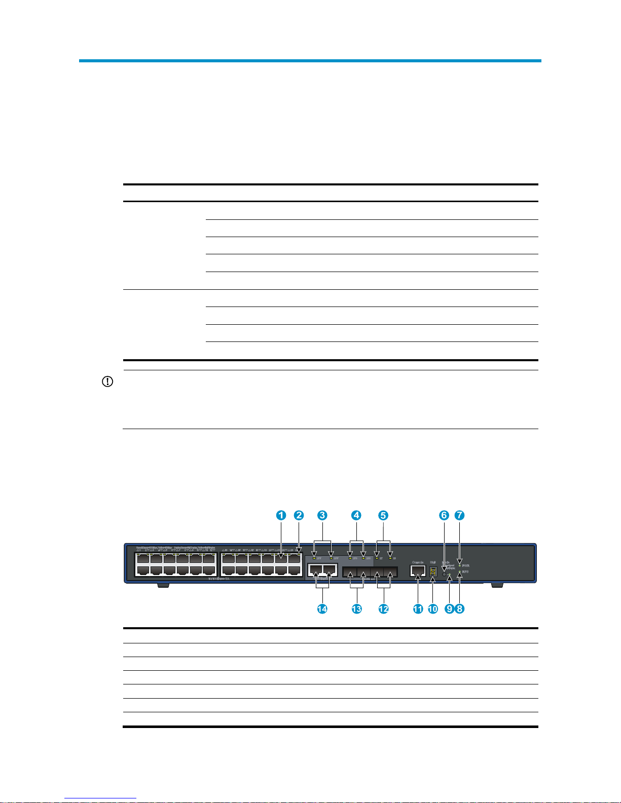
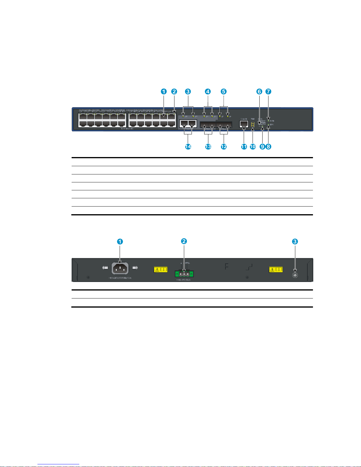
Figure 1 3600-24 v2 EI front panel
(1) 10/100Base-TX auto-sensing Ethernet port (2) 10/100Base-TX Ethernet port LED
(3) 1000Base-T Ethernet combo port LED (4) 1000Base-X SFP combo port LED
(5) 1000Base-X SFP port LED (6) Port LED mode switching button
(7) System status LED (PWR) (8) DC power LED (RPS)
(9) Port mode LED (10) Seven-segment LED
(11) Console port (12) 1000Base-X SFP port
(13) 1000Base-X SFP combo port (14) 1000Base-T Ethernet combo port
1
Page 7
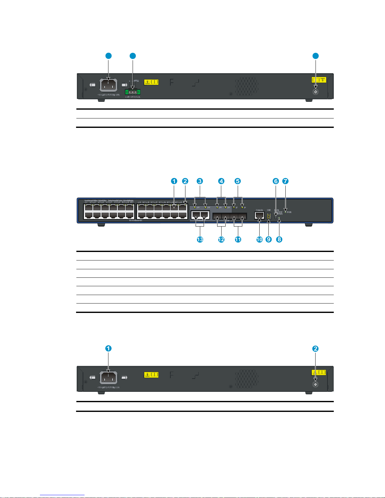
Figure 2 3600-24 v2 EI rear panel
1
2 3
(1) AC-input power receptacle (2) DC-input terminal block
(3) Grounding screw
3600-24 v2 SI Switch panel views
Figure 3 3600-24 v2 SI front panel
(1) 10/100Base-TX auto-sensing Ethernet port (2) 10/100Base-TX Ethernet port LED
(3) 1000Base-T Ethernet port (combo) LED (4) 1000Base-X SFP combo port LED
(5) 1000Base-X SFP port LED (6) Port LED mode switching button
(7) System status LED (PWR) (8) Port mode LED
(9) Seven-segment LED (10) Console port
(11) 1000Base-X SFP port (12) 1000Base-X SFP combo port
(13) 1000Base-T Ethernet combo port
Figure 4 3600-24 v2 SI rear panel
(1) AC-input power receptacle (2) Grounding screw
2
Page 8
3600-48 v2 EI Switch panel views
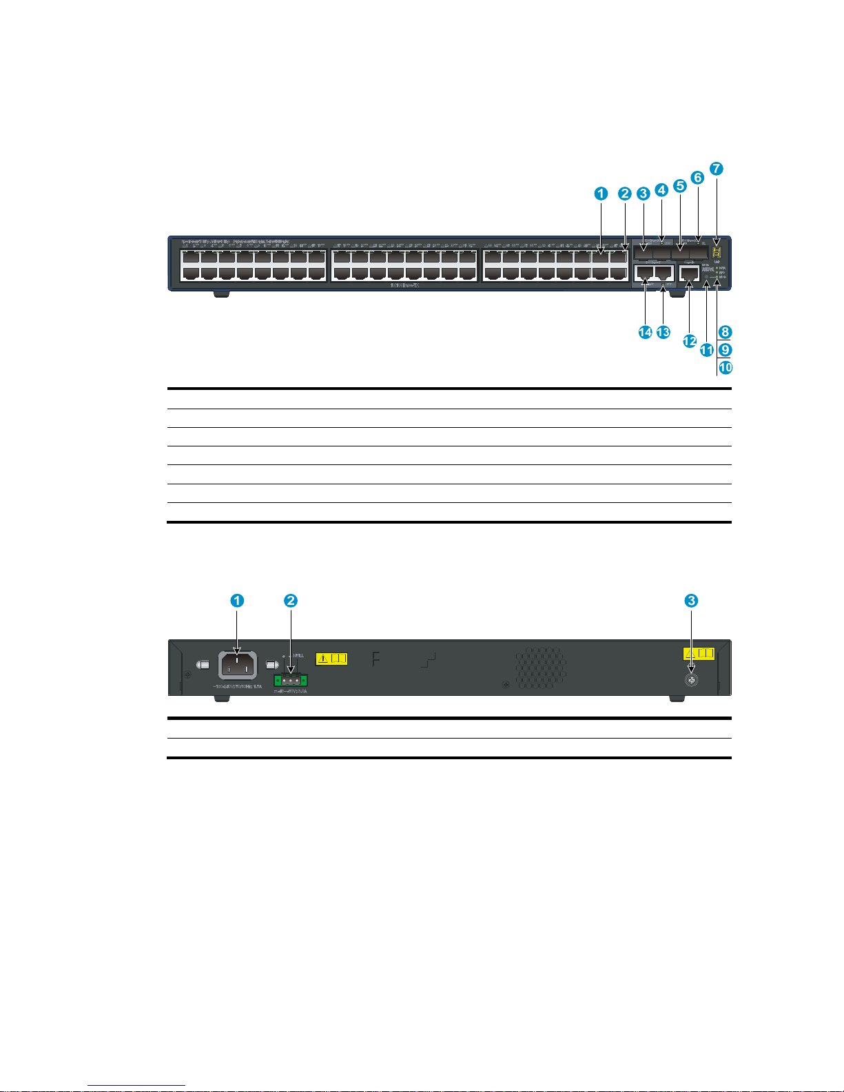
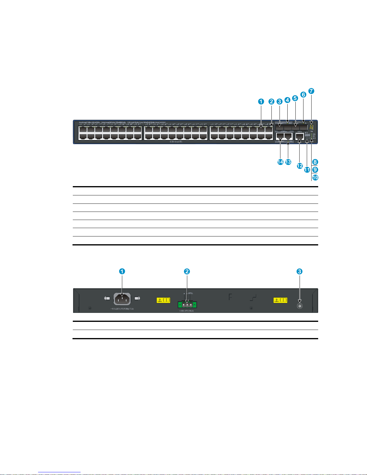
Figure 5 3600-48 v2 EI front panel
(1) 10/100Base-TX auto-sensing Ethernet port (2) 10/100Base-TX Ethernet port LED
(3) 1000Base-X SFP combo port (4) 1000Base-X SFP combo port LED
(5) 1000Base-X SFP port (6) 1000Base-X SFP port LED
(7) Seven-segment LED (8) System status LED (PWR)
(9) DC power module status LED (RPS) (10) Port mode LED (Mode)
(11) Port LED mode switching button (12) Console port
(13) 1000Base-T Ethernet port LED (14) 1000Base-T Ethernet port
Figure 6 3600-48 v2 EI rear panel
(1) AC-input power receptacle (2) DC-input terminal block
(3) Grounding screw
3
Page 9
3600-48 v2 SI Switch panel views
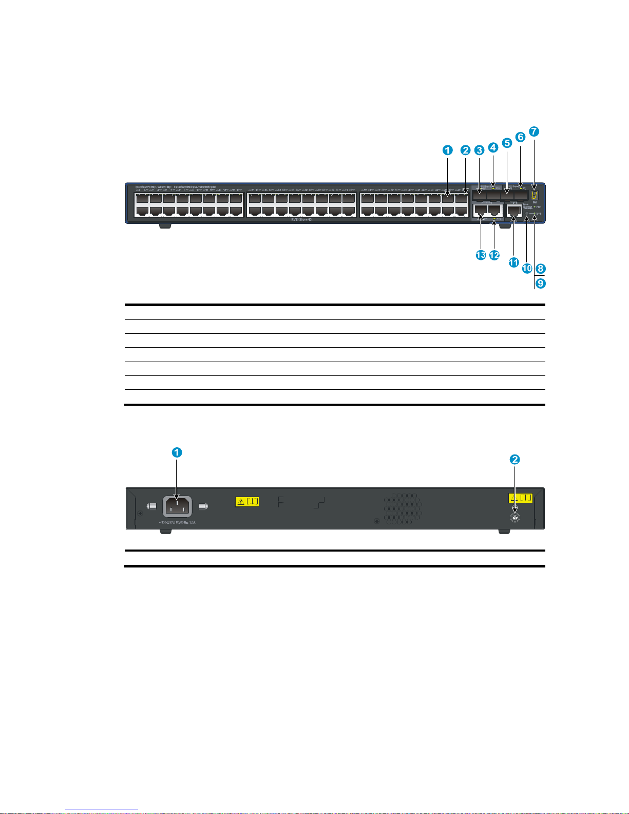
Figure 7 3600-48 v2 SI front panel
(1) 10/100Base-TX auto-sensing Ethernet port (2) 10/100Base-TX Ethernet port LED
(3) 1000Base-X SFP combo port (4) 1000Base-X SFP combo port LED
(5) 1000Base-X SFP port (6) 1000Base-X SFP port LED
(7) Seven-segment LED (8) System status LED (PWR)
(9) Port mode LED (Mode) (10) Port LED mode switching button
(11) Console port (12) 1000Base-T Ethernet port LED
(13) 1000Base-T Ethernet port
Figure 8 3600-48 v2 SI rear panel
(1) AC-input power receptacle (2) Grounding screw
4
Page 10
3600-24-PoE+ v2 EI Switch/3600-24-PoE+ v2 SI
Switch panel views
Figure 9 3600-24-PoE+ v2 EI Switch/3600-24-PoE+ v2 SI front panel
(1) 10/100Base-TX auto-sensing Ethernet port (2) 10/100Base-TX Ethernet port LED
(3) 1000Base-T Ethernet combo port LED (4) 1000Base-X SFP combo port LED
(5) 1000Base-X SFP port LED (6) Port LED mode switching button
(7) System status LED (PWR) (8) DC power module status LED (RPS)
(9) Port mode LED (10) Seven-segment LED
(11) Console port (12) 1000Base-X SFP port
(13) 1000Base-X SFP combo port (14) 1000Base-T Ethernet combo port
Figure 10 3600-24-PoE+ v2 EI Switch/3600-24-PoE+ v2 SI rear panel
(1) AC-input power receptacle (2) DC-input terminal block
(3) Grounding screw
5
Page 11
3600-48-PoE+ v2 EI Switch/3600-48-PoE+ v2 SI
Switch panel views
Figure 11 3600-48-PoE+ v2 EI Switch/3600-48-PoE+ v2 SI front panel
(1) 10/100Base-TX auto-sensing Ethernet port (2) 10/100Base-TX Ethernet port LED
(3) 1000Base-X SFP combo port (4) 1000Base-X SFP combo port LED
(5) 1000Base-X SFP port (6) 1000Base-X SFP port LED
(7) Seven-segment LED (8) System status LED (PWR)
(9) DC power module status LED (RPS) (10) Port mode LED (Mode)
(11) Port LED mode switching button (12) Console port
(13) 1000Base-T Ethernet port LED (14) 1000Base-T Ethernet port
Figure 12 3600-48-PoE+ v2 EI Switch/3600-48-PoE+ v2 SI rear panel
(1) AC-input power receptacle (2) DC-input terminal block
(3) Grounding screw
6
Page 12
7
3600-24-SFP v2 EI Switch panel views
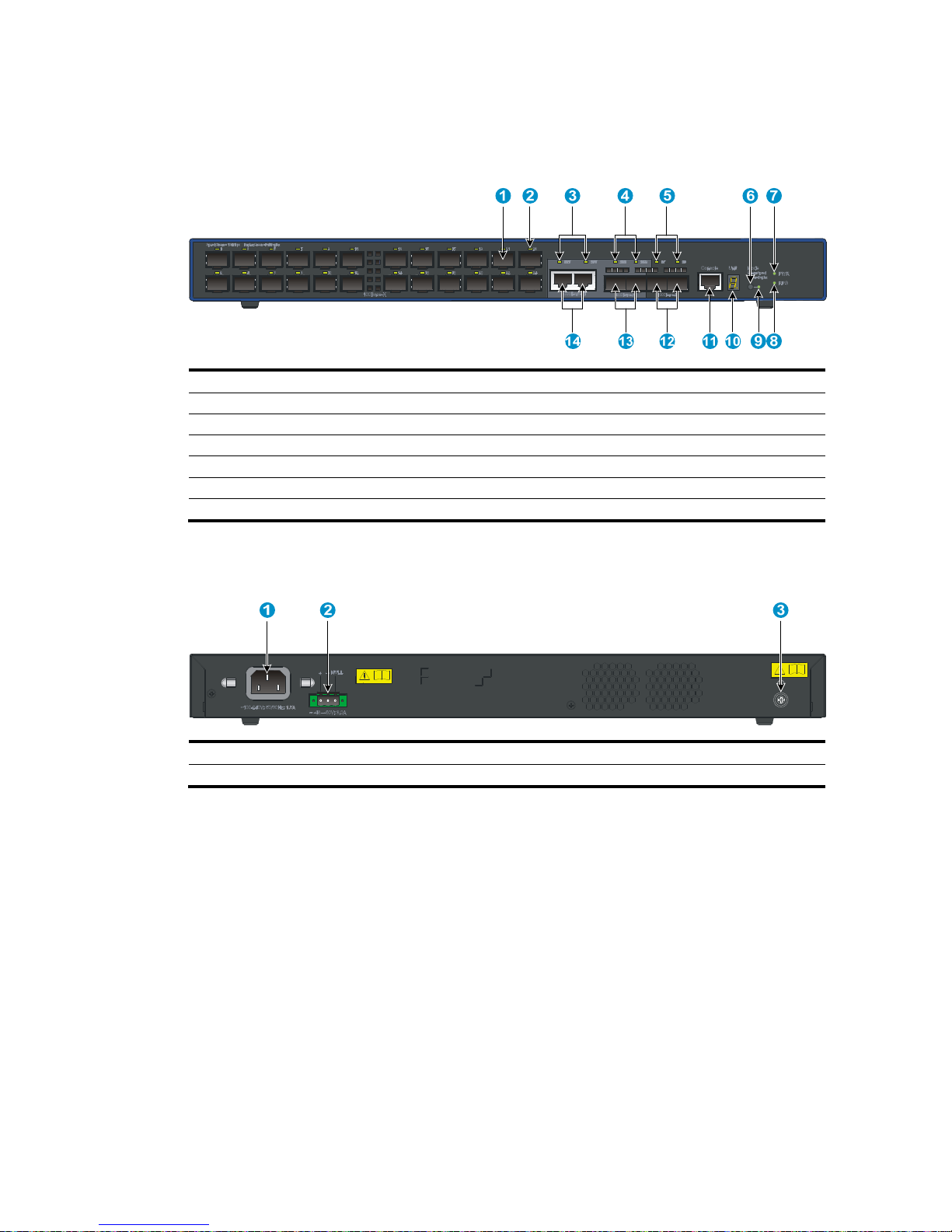
Figure 13 3600-24-SFP v2 EI front panel
(1) 100Base-X SFP port (2) 100Base-X SFP port LED
(3) 1000Base-T Ethernet combo port LED (4) 1000Base-X SFP combo port LED
(5) 1000Base-X SFP port LED (6) Port LED mode switching button
(7) System status LED (PWR) (8) DC power LED (RPS)
(9) Port mode LED (10) Seven-segment LED
(11) Console port (12) 1000Base-X SFP port
(13) 1000Base-X SFP combo port (14) 1000Base-T Ethernet combo port
Figure 14 3600-24-SFP v2 EI rear panel
(1) AC-input power receptacle (2) DC-input terminal block
(3) Grounding screw
Page 13

Preparing for installation
Safety recommendations
To avoid any equipment damage or bodily injury caused by improper use, read the following safety
recommendations before installation. Note that the recommendations do not cover every possible
hazardous condition.
• Before cleaning the switch, unplug all power cords from the switch. Do not clean the switch with wet
cloth or liquid.
• Do not place the switch near water or in a damp environment. Prevent water or moisture from
entering the switch chassis.
• Do not place the switch on an unstable case or desk. The switch might be severely damaged in case
of a fall.
• Ensure proper ventilation of the equipment room and keep the air inlet and outlet vents of the switch
free of obstruction.
• Connect the yellow-green protection grounding cable before power-on.
• Make sure that the operating voltage is in the required range.
• To avoid electrical shocks, do not open the chassis while the switch is operating or when the switch
is just powered off.
• When replacing transceiver modules, wear an ESD-preventive wrist strap to avoid damaging the
units.
Examining the installation site
The HP 3600 v2 Switch Series must be used indoors. You can mount the switch in a rack or on a
workbench, but make sure:
• Adequate clearance is reserved at the air inlet and exhaust vents for ventilation.
• The rack or workbench has a good ventilation system.
• The rack is sturdy enough to support the switch and its accessories.
• The rack or workbench is well earthed.
To ensure normal operation and long service life of your switch, install it in an environment that meets the
requirements described in the following subsections.
Temperature/humidity
Maintain appropriate temperature and humidity in the equipment room.
• Lasting high relative humidity can cause poor insulation, electricity creepage, mechanical property
change of materials, and metal corrosion.
8
Page 14

• Lasting low relative humidity can cause washer contraction and ESD and bring problems including
loose captive screws and circuit failure.
• High temperature can accelerate the aging of insulation materials and significantly lower the
reliability and lifespan of the switch.
For the temperature and humidity requirements of different switch models, see “Environmental
specifications”.
Cleanness
Dust buildup on the chassis may result in electrostatic adsorption, which causes poor contact of metal
components and contact points, especially when indoor relative humidity is low. In the worst case,
electrostatic adsorption can cause communication failure.
Table 2 Dust concentration limit in the equipment room
Substance Concentration limit (
p
articles/m³)
Dust ≤ 3 x 10⁴ (no visible dust on the tabletop over three days)
NOTE:
Dust diameter ≥ 5 μm
The equipment room must also meet strict limits on salts, acids, and sulfides to eliminate corrosion and
premature aging of components, as shown in Table 3.
Table 3 Harmful gas limits in the equipment room
Gas Maximum concentration (m
g
/m3)
SO2 0.2
H2S 0.006
NH3 0.05
Cl2 0.01
EMI
All electromagnetic interference (EMI) sources, from outside or inside of the switch and application
system, adversely affect the switch in a conduction pattern of capacitance coupling, inductance coupling,
electromagnetic wave radiation, or common impedance (including the grounding system) coupling. To
prevent EMI, take the following actions:
• If AC power is used, use a single-phase three-wire power receptacle with protection earth (PE) to
filter interference from the power grid.
• Keep the switch far away from radio transmitting stations, radar stations, and high-frequency
devices.
• Use electromagnetic shielding, for example, shielded interface cables, when necessary.
• Route interface cables only indoors to prevent signal ports from getting damaged by overvoltage or
overcurrent caused by lightning strikes.
9
Page 15
10
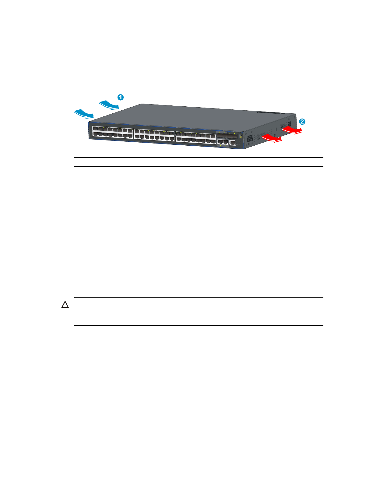
Cooling requirements
The built-in fans in the 3600 v2 switches blow air from the left to the right of the chassis for heat
dissipation, as shown in Figure 15.
Figure 15 Airflow through the 3600 v2 switches
(1) Air intake (2) Air exhaust
For adequate heat dissipation, plan the installation site according to the airflow of your switch, and
adhere to the following requirements:
• Leave a clearance of at least 10 cm (3.94 in) around the air intake and exhaust vents.
• Consider the heat dissipation of the installation site when determining air-conditioning
requirements to ensure that cool air can enter the switch.
• Make sure the hot air generated by equipment at the bottom of the rack is not drawn in the intake
of the equipment above.
• The installation site has a good cooling system.
Laser safety
The 3600 v2 switches are Class 1 laser devices.
CAUTION:
Do not stare into any fiber port when the switch has power. The laser li
g
ht emitted from the optical fiber
may hurt your eyes.
Installation tools
• Flat-blade screwdriver
• Phillips screwdriver
• ESD-preventive wrist strap
All these installation tools are user supplied.
Page 16
Installing the switch
W
ARNING!
Keep the tamper-proof seal on a mountin
g
screw on the chassis cover intact, and if you want to open the
chassis, contact your local HP agent for permission. Otherwise, HP shall not be liable for any consequence
caused thereby.
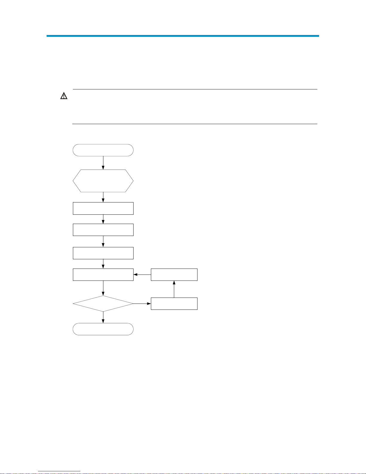
Figure 16 Hardware installation flow
Start
Install the switch to a
19-in rack or
workbench
Ground the switch
Connect the power cord
Verify the installation
Power on the switch
Operating properly?
End
Power off the switch
Troubleshoot the
switch
Yes
No
Installing the switch in a 19-inch rack
The 3600 v2 switch is available with one pair of mounting brackets, as shown in Figure 17.
11
Page 17
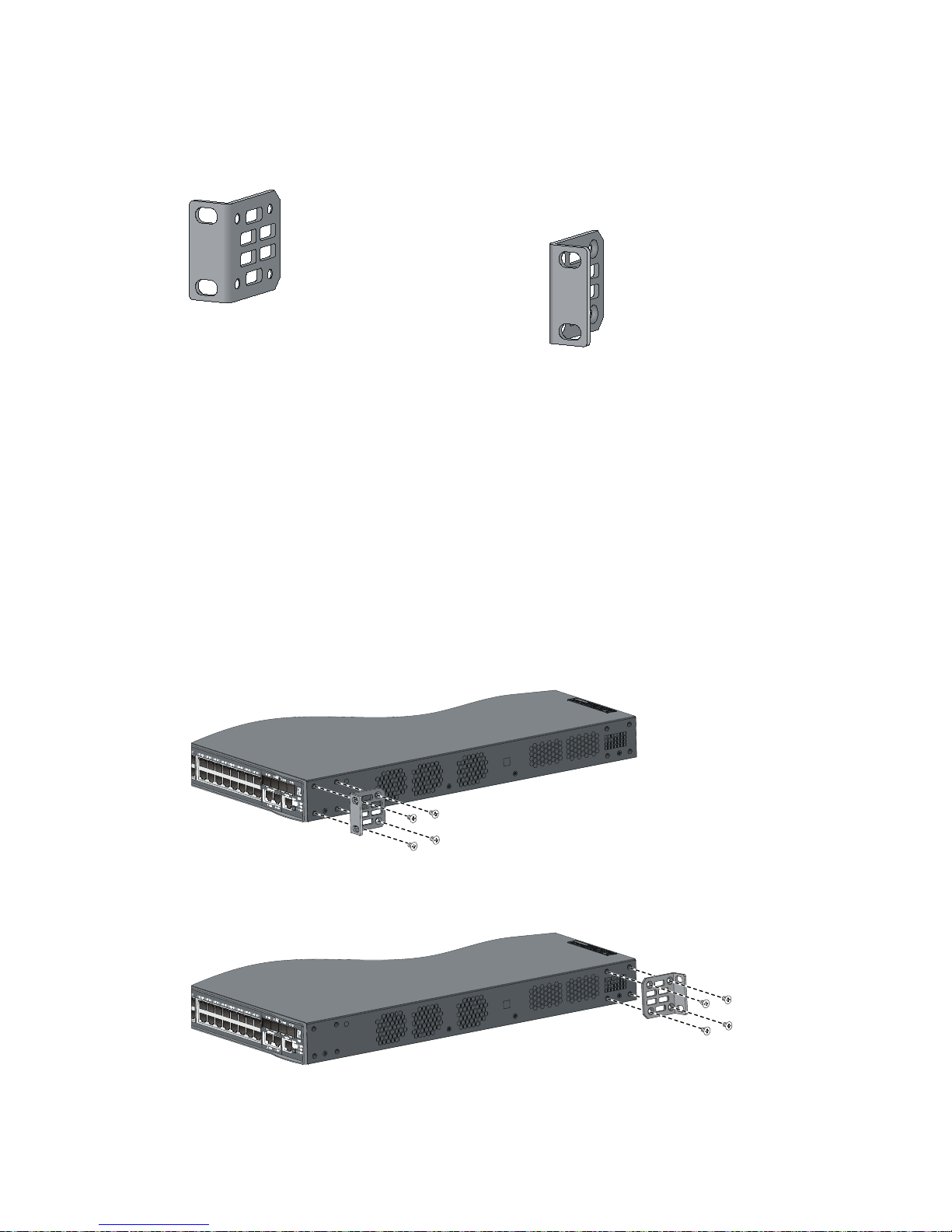
Mounting bracket kit
Figure 17 Mounting bracket kit
Attaching the mounting brackets to the chassis
The 360 0 v2 swi tch provides o ne front mount i ng posi tion and one rear mounting position. You can install
the mounting brackets as needed.
1. Wear an ESD-preventive wrist strap, and make sure that the wrist strap makes good skin contact
and is well grounded.
2. Align one mounting bracket with the screw holes in the front-mounting position (Figure 18) or the
rear-mounting position (Figure 19)..
3. Use M4 screws (supplied with the switch) to fix the mounting bracket to the switch chassis.
4. Repeat the proceeding steps to attach the other mounting bracket to the chassis.
Figure 18 1U mounting bracket front mounting position
Figure 19 1U mounting bracket rear mounting position
12
Page 18
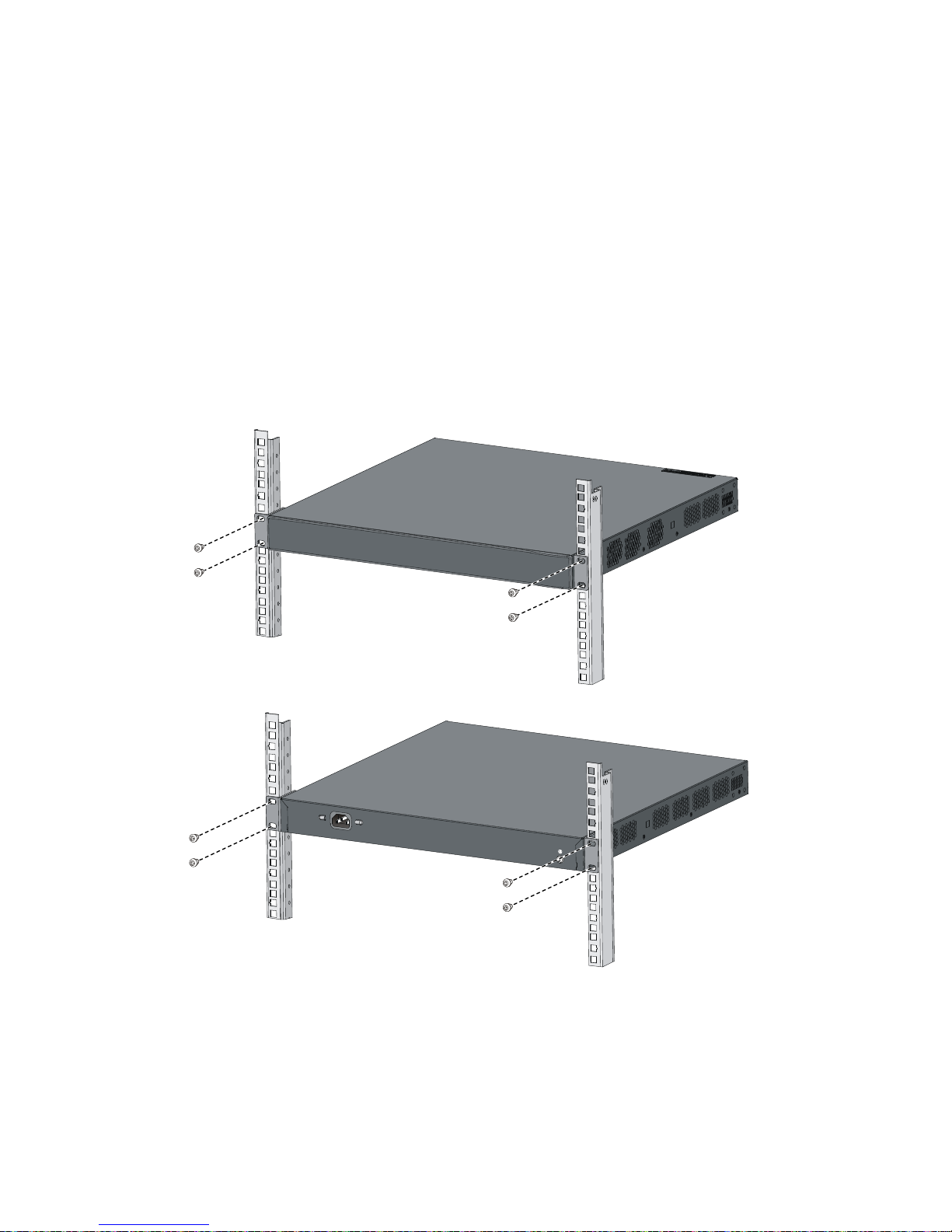
Rack-mounting an 3600 v2 switch
This installation task requires two persons. To mount the switch in a rack:
1. Wear an ESD-preventive wrist strap and make sure it makes good skin contact and is well
grounded.
2. Check that the mounting brackets have been securely attached to the switch chassis.
3. Install cage nuts (user-spplied) in the mounting holes in the rack posts.
4. One person holds the switch chassis and aligns the mounting brackets with the mounting holes in
the rack posts, and the other person fixes the mounting brackets with anti-rust screws (user-supplied)
to the rack.
5. Check that the switch chassis is horizontal and tighten the screws.
Figure 20 Mount an 3600 v2 switch in a rack
Mounting the switch on a workbench
If a standard 19-inch rack is not available, you can place an 3600 v2 switch on a clean, flat workbench,
as follows:
1. Check that the workbench is sturdy and well grounded.
13
Page 19
2.
Place the switch with bottom up, and clean the round holes in the chassis bottom with dry cloth.
3. Attach the rubber feet to the four round holes in the chassis bottom.
4. Place the switch with upside up on the workbench.
IMPORTANT:
• Ensure good ventilation and 10 cm (3.9 in) of clearance around the chassis for heat dissipation.
• Avoid placing heavy objects on the switch.
Grounding the switch
W
ARNING!
Correctly connecting the switch grounding cable is crucial to lightning protection and EMI protection.
NOTE:
The power and grounding terminals in this section are for illustration only.
The power input end of the switch has a noise filter, whose central ground is directly connected to the
chassis to form the chassis ground (commonly known as PGND). You must securely connect this chassis
ground to the earth so the faradism and leakage electricity can be safely released to the earth to
minimize EMI susceptibility of the switch.
You can ground the switch in one of the following ways, depending on the grounding conditions
available at the installation site:
• Grounding the switch with a grounding strip
• Grounding the switch by using the AC power cord
• Grounding the switch with a grounding conductor buried in the earth ground
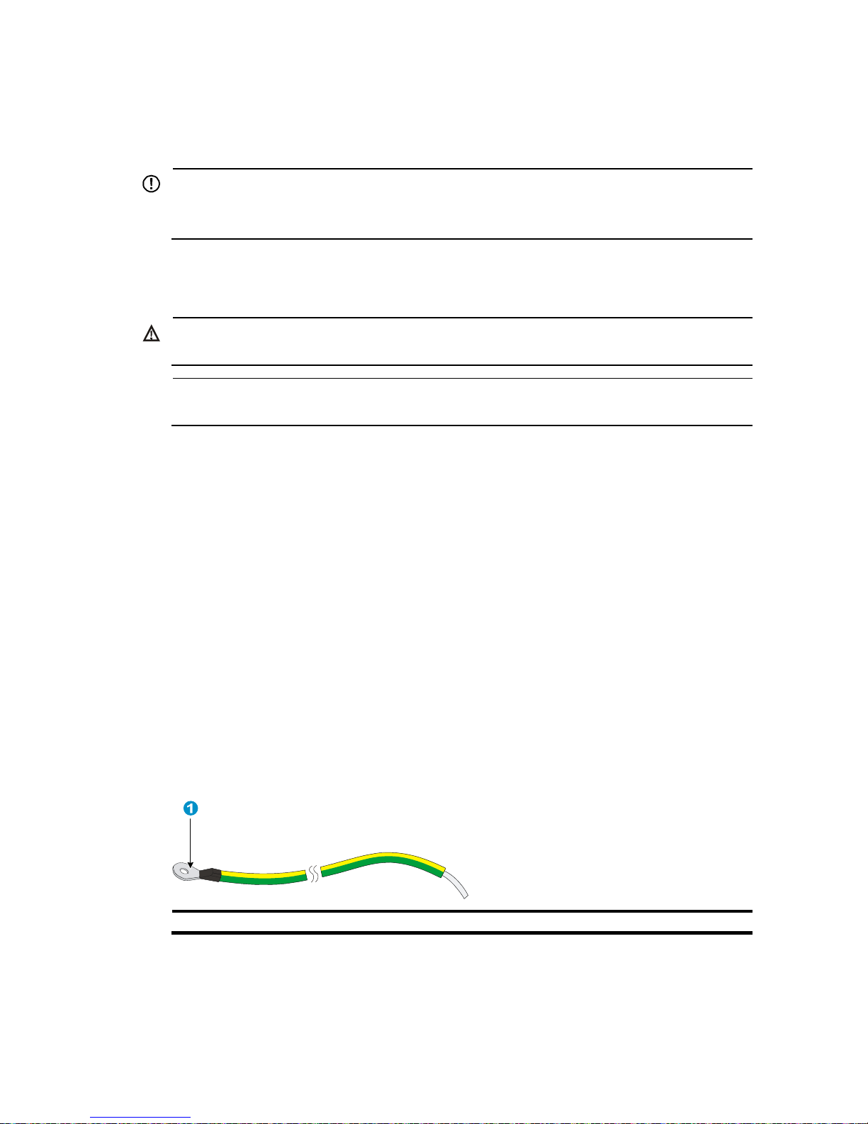
Grounding cable
The 3600 v2 Switch Series is provided with a yellow-green grounding cable. One end of the cable has
an OT terminal, and the other end is naked and soldered, as shown in Figure 21.
Figure 21 Grounding cable
(1) OT terminal of the grounding cable
14
Page 20

Grounding the switch with a grounding strip
When a grounding strip is available at the installation site, connect the grounding cable to the
grounding strip.
CAUTION:
• The supplied grounding cable of the 3600 v2 Switch Series does not have an auxiliary OT terminal.
• Connect the
g
rounding cable to the earthing system in the equipment room. Do not connect it to a fire
main or lightning rod.
Connecting the grounding cable to the switch
Follow these steps to connect the grounding cable:
1. Remove the grounding screw on the rear panel of the switch chassis.
2. Attach the grounding screw to the OT terminal of the grounding cable.
3. Use a screwdriver to fasten the grounding screw into the grounding screw hole.
Figure 22 Connect the grounding cable to the grounding hole of switch
6
5
4
1 2 3
(1) Chassis rear panel (2) Grounding sign
(3) Grounding hole
(4) OT terminal
(5) Grounding cable (6) Grounding screw
Connecting the grounding cable to a grounding strip
Follow these steps to connect the grounding cable to a grounding strip:
1. Remove the hex nut from the grounding strip.
2. Cut the grounding cable to a proper length according to the distance between the switch and the
grounding strip.
3. Make the connector on the grounding cable:
15
Page 21

• If you have an OT terminal, follow callout A in Figure 23 to make the connector: Peel 5 mm (0.20
in) of insulation sheath by using a wire stripper, and then insert the naked metal part through the
insulation covering into the end of the OT terminal. Secure the metal part of the cable to the OT
terminal with a crimper, and then cover it with the insulation covering. Then heat the insulation
covering with a blower to make it completely cover the metal part.
• If you do not have an OT terminal, follow callout B in Figure 23 to make the connector: Peel the
insulation sheath by an appropriate length by using a wire stripper, and then bend the naked metal
part.
4. Connect the made connector to the grounding post of the grounding strip, and then fasten it with
a hex nut, as shown in Figure 24.
Figure 23 Make the grounding cable connector
Figure 24 Connect the grounding cable to a grounding strip
(1) Grounding post
(2) Grounding strip
(3) Grounding cable (4) Hex nut
Grounding the switch by using the AC power cord
If the installation site has no grounding strips, you can ground an AC-powered switch through the
protective earth (PE) wire of the power cord, but must make sure:
• The power cord has a PE terminal.
16
Page 22

• The ground contact in the power outlet is securely connected to the ground in the power distribution
room or on the AC transformer side.
• The power cord is securely connected to the power outlet.
NOTE:
If the
g
round contact in the power outlet is not connected to the ground, report the problem and reconstruc
t
the grounding system.
Figure 25 Ground through the PE wire of the AC power supply
(1) Three-wire AC power cable (2) Chassis rear panel
Grounding the switch with a grounding conductor buried in the
earth ground
If the installation site has no grounding strips, but earth ground is available, hammer a 0.5 m (1.64 ft) or
longer angle iron or steel tube into the earth ground to serve as a grounding conductor.
The dimensions of the angle iron must be at least 50 × 50 × 5 mm (1.97 × 1.97 × 0.20 in). The steel tube
must be zinc-coated and its wall thickness must be at least 3.5 mm (0.14 in).
Weld the yellow-green grounding cable to the angel iron or steel tube and treat the joint for corrosion
protection.
17
Page 23

Figure 26 Ground the switch by burying the grounding conductor into the earth ground
(1) Grounding screw (2) Grounding cable (3) Earth
(4) Joint (5) Grounding conductor (6) Cassis rear panel
Connecting the power cord
CAUTION:
Before powering on the switch, you must connect the power cord and make sure the switch is well
grounded.
Connecting an AC power cord
Follow these steps to connect an AC power cord:
1. Wear an ESD-preventive wrist strap, and make sure the wrist strap makes good skin contact and
is well grounded.
2. Insert the plug of the AC power cord into the AC power receptacle (see Figure 27).
3. Connect the other end of the AC power cord to the AC power source.
4. Check the power LED (PWR) on the front panel. If the LED is on, the power cord is properly
connected.
Figure 27 Connect the AC power cord
18
Page 24

Connecting a DC power cord
NOTE:
• The 3600-24 v2 SI Switch and 3600-48 v2 SI Switch do not support DC power supply.
• No DC power cord is supplied with the 3600 v2 Switch Series.
The 3600 v2 Switch Series provides DC power input.
• Non PoE switches (3600-24 v2 EI Switch, 3600-48 v2 EI Switch, and 3600-24-SFP v2 EI Switch)
can be powered by the –48VDC power supply in the equipment room.
• PoE swi tches (3600 -24-PoE+ v2 EI Switch, 3600 -24-PoE+ v2 SI Switch, 3600 - 48-PoE+ v2 EI Switch,
and 3600-48-PoE+ v2 SI Switch) can be powered by an RPS power source.
The procedures for connecting a –48 VDC power source in the equipment room and an RPS power
source are similar.
Follow these steps to connect a DC power cord:
1. Wear an ESD-preventive wrist strap and make sure it makes good skin contact and is well
grounded.
2. Keep the upside of the DC plug on top and plug it in the DC re c eptacle (see c a l lout 1 in Figure 28).
(If you plug it upside down, the insertion is not smooth because of the specific structure design of
the DC receptacle and the DC plug.)
3. Use a flat-blade screwdriver to fix the two screws on the DC plug to secure the plug to the DC
receptacle (see callout 2 in Figure 28).
4. Connect the other end of the DC power cord to the –48 VDC power source in the equipment room
or the RPS power source.
5. Check the power LED (PWR) on the front panel. If the LED is on, the power cord is properly
connected. If you also connect an AC power cord to the switch, check the RPS LED to confirm the
RPS input status.
Figure 28 Connect a DC power cord to the switch
CAUTION:
Pay attention to the positive (+) and negative (-) marks on the power cord to avoid connection mistakes.
19
Page 25

20
Verifying the installation
After you complete the installation, verify that:
• There is enough space for heat dissipation around the switch, and the rack or workbench is stable.
• The grounding cable is securely connected.
• The correct power source is used.
• The power cords are properly connected.
• All the interface cables are cabled indoors. If any cable is routed outdoors, verify that the socket
strip with lightning protection and lightning arresters for network ports have been properly
connected.
Page 26

Accessing the switch for the first time
Setting up the configuration environment
The first time you access the switch you must use a console cable to connect a console terminal, for
example, a PC, to the console port on the switch.
Figure 29 Connect the console port to a terminal
Connecting the console cable
Console cable
A console cable is an 8-core shielded cable, with a crimped RJ-45 connector at one end for connecting
to the console port of the switch, and a DB-9 female connector at the other end for connecting to the
serial port on the console terminal.
Figure 30 Console cable
Connection procedure
To connect a terminal, for example, a PC, to the switch:
1. Plug the DB-9 female connector of the console cable to the serial port of the PC.
21
Page 27

2.
Connect the RJ-45 connector to the console port of the switch.
W
ARNING!
• Identify the mark on the console port to ensure that you are connecting to the correct port.
• The serial ports on PCs do not support hot swapping. If the switch has been powered on, connect the
console cable to the PC before connecting to the switch, and when you disconnect the cable, first
disconnect from the switch.
Setting terminal parameters
To configure and manage the switch, you must run a terminal emulator program on the console terminal.
The following are the required terminal settings:
• Bits per second—9,600
• Data bits—8
• Parity—None
• Stop bits—1
• Flow control—None
• Emulation—VT100
To set terminal parameters, for example, on a Windows XP HyperTerminal:
1. Select Start > All Programs > Accessories > Communications > HyperTerminal.
The Connection Description dialog box appears.
2. Enter the name of the new connection in the Name field and click OK.
Figure 31 Connection description
3. Select the serial port to be used from the Connect using list, and click OK.
22
Page 28

Figure 32 Set the serial port used by the HyperTerminal connection
4. Set Bits per second to 9600, Data bits to 8, Parity to None, Stop bits to 1, and Flow control to None,
and click OK.
Figure 33 Set the serial port parameters
5. Select File > Properties in the HyperTerminal window.
23
Page 29

Figure 34 HyperTerminal window
6. On the Settings tab, set the emulation to VT100 and click OK.
Figure 35 Set terminal emulation in Switch Properties dialog box
24
Page 30

25
Powering on the switch
Checking before power-on
Before powering on the switch, verify that:
• The power cord is properly connected.
• The power supply voltage meets the requirement of the switch.
• The console cable is properly connected; the terminal or PC used for configuration has been started;
and the configuration parameters have been set.
Powering on the switch
The 3600 v2 switches have the same Boot ROM display style. This document uses the Boot ROM output
on an 3600-48-PoE+ v2 EI switch as an example:
Starting......
************************************************************************
* *
* HP 3600-48-PoE+ v2 EI Switch BOOTROM, Version 105 *
* *
************************************************************************
Copyright (c) 2010-2011 Hewlett-Packard Development Company, L.P.
Creation Date : Jan 13 2011, 16:39:15
CPU Clock Speed : 600MHz
Memory Size : 256MB
Flash Size : 128MB
CPLD Version : 001
PCB Version : Ver.B
Mac Address : 000fe2100000
Press Ctrl-B to enter Extended Boot menu...0
Press Ctrl + B at the prompt within one second to access the Boot menu, or wait for the system to
automatically start up.
NOTE:
• The system has two startup modes: normal startup and fast startup. The normal startup mode requires a
little longer time than the fast startup mode because of more self-test operations.
• By default, the system starts up in fast mode and the waiting time is one second. If you set the startup
mode to normal, the waiting time is five seconds. The following section describes the setting of the
startup mode.
• If you press Ctrl + B within one second, the system displays the following information:
Please input BootRom password:
Enter the B oot ROM password (t he i n itia l pas sword i s nul l) . Then the syste m dis plays t h e Bo ot ROM m enu.
Page 31

26
BOOT MENU
1. Download application file to flash
2. Select application file to boot
3. Display all files in flash
4. Delete file from flash
5. Modify BootRom password
6. Enter BootRom upgrade menu
7. Skip current system configuration
8. Set BootRom password recovery
9. Set switch startup mode
0. Reboot
Enter your choice(0-9):
Table 4 Description on the fields
Item Descri
p
tion
1. Download application file to flash Download a software package file to the Flash memory.
2. Select application file to boot Select the software package file to boot.
3. Display all files in flash Display all files in the Flash memory
4. Delete file from flash Delete files from the Flash memory
5. Modify BootRom password Modify the Boot ROM password
6. Enter BootRom upgrade menu Access the Boot ROM update menu.
7. Skip current system configuration
Start the switch with the factory default configuration. This is a
one-time operation and does not take effect at the n ext reb oot. You
use this option when you forget the console login password.
8. Set BootRom password recovery
Disable or enable the Boot ROM password recovery function. By
default, Boot ROM recovery is enabled. You can disable this
function to protect system security.
9. Set switch startup mode
Set the startup mode of the switch to normal (full) mode or fast
mode, as described in “Changing the startup mode.”
0. Reboot Restart the switch
• If you perform no operation or press a key other than Ctrl + B within one second, once the
remaining waiting time becomes zero, the system begins to automatically start up and the following
information is displayed:
Starting to get the main application file--flash:/3600_v2.app!.................
...............................................................................
...............................................................................
....
The main application file is self-decompressing................................
...............................................................................
...............................................................................
...............................................................................
...............................................................................
...............................................................................
Page 32

27
...............................................................................
...............................................................................
...............................................................................
...............................................................................
...............................................................................
...............................................................................
...............................................................................
.....................................Done!
System is starting...
Startup configuration file does not exist.
It will take a long time to get configuration file, please wait...
Retrieving configuration file failed!
User interface aux0 is available.
Press ENTER to get started.
Press Enter at the prompt, and you can configure the switch when the prompt <HP> appears.
NOTE:
W
hen the switch boots for the first time, it automatically obtains the configuration file through the DHCP
server. If it fails to obtain the configuration file, it boots with the default configuration.
Changing the startup mode
By default, the system starts up in fast boot mode. To change the boot mode to normal, press Ctrl + B
within one second to enter the Boot ROM menu:
BOOT MENU
1. Download application file to flash
2. Select application file to boot
3. Display all files in flash
4. Delete file from flash
5. Modify BootRom password
6. Enter BootRom upgrade menu
7. Skip current system configuration
8. Set BootRom password recovery
9. Set switch startup mode
0. Reboot
Enter your choice(0-9):
Enter 9. The system prompts you to change the startup mode:
The current mode is fast startup mode!
Are you sure you want to change it to full startup mode? Yes or No(Y/N)
Enter Y. The system displays the following information:
Setting startup mode...done!
Page 33

28
BOOT MENU
1. Download application file to flash
2. Select application file to boot
3. Display all files in flash
4. Delete file from flash
5. Modify BootRom password
6. Enter BootRom upgrade menu
7. Skip current system configuration
8. Set BootRom password recovery
9. Set switch startup mode
0. Reboot
Enter your choice(0-9):
Enter 0. The system reboots in normal startup mode and displays the following information:
Starting......
************************************************************************
* *
* HP 3600-48-PoE+ v2 EI Switch BOOTROM, Version 105 *
* *
************************************************************************
Copyright (c) 2010-2011 Hewlett-Packard Development Company, L.P.
Creation Date : Jan 13 2011, 16:39:15
CPU Clock Speed : 600MHz
Memory Size : 256MB
Flash Size : 128MB
CPLD Version : 001
PCB Version : Ver.B
Mac Address : 000fe2100000
Press Ctrl-B to enter Extended Boot menu...0
In normal startup mode, the waiting time is five seconds. If you press Ctrl + B within five s e conds, the Boot
ROM menu is displayed. If you perform no operation or press a key other than Ctrl + B wi thin five sec o nds,
the system begins to automatically start up and the following information is displayed:
Starting to get the main application file--flash:/3600_v2.app!.................
...............................................................................
...............................................................................
....
The main application file is self-decompressing................................
...............................................................................
...............................................................................
...............................................................................
...............................................................................
...............................................................................
...............................................................................
Page 34

29
...............................................................................
...............................................................................
...............................................................................
...............................................................................
...............................................................................
...............................................................................
.....................................Done!
System is starting...
Board checking.......................LSJ252TPA
SDRAM fast selftest........................OK!
Flash fast selftest........................OK!
CPLD selftest..............................OK!
Switch chip selftest.......................OK!
PHY selftest...............................OK!
Please check leds....................FINISHED!
User interface aux0 is available.
Press ENTER to get started.
Press Enter at the prompt, and you can configure the switch when the prompt <HP> appears.
NOTE:
For more information about the configuration commands and command line interface, see the
HP 360
0
v2 Switch Series Configuration Guides
and the
HP 3600 v2 Switch Series Command References
.
Page 35

Setting up an IRF fabric
You can use HP Intelligent Resilient Framework (IRF) technology to connect and virtualize 3600 v2
switches into a virtual switch called an “IRF fabric” or “IRF virtual device” for flattened network topology,
and high availability, scalability, and manageability.
This chapter includes these sections:
• IRF fabric setup flowchart
• Planning IRF fabric setup
• Configuring basic IRF settings
• Connecting the physical IRF ports
• Accessing the IRF fabric to verify the configuration
IRF fabric setup flowchart
Figure 36 IRF fabric setup flowchart
Start
Plan IRF fabric setup
Install IRF member switches
Connect ground wires and
power cords
Power on the switches
Configure basic IRF settings
Connect the physical IRF ports
Switches elected as slaves
reboot and the IRF fabric is
established automatically
End
30
Page 36

Follow these steps to set up an IRF fabric:
Ste
p
Description
1. Plan IRF fabric setup
Plan the installation site and IRF fabric setup parameters. Complete the
following tasks:
• Planning IRF fabric size and the installation site
• Identifying the master switch and planning IRF member IDs
• Planning IRF topology and connections
• Identifying physical IRF ports on the member switches
• Planning the cabling scheme
2. Install IRF member
switches
See “Installing the switch in a 19-inch rack” or “Mounting the switch on a
workbench.”
3. Connect ground wires
and power cords
See “Grounding the switch” and “Connecting the power cord.”
4. Powe r on the switch es
N/A
5. Configure basic IRF
settings
For more information about IRF, see the HP 3600 v2 Switch Series IRF
Configuration Guide.
6. Connect the physical IRF
ports
Connect physical IRF ports on switches. Use Ethernet cables, SFP transceiver
modules, and fibers to connect ports over a long distance, or use SFP IRF
modules to connect ports over a short distance.
All switches except the master switch automatically reboot, and the IRF fabric
is established.
Planning IRF fabric setup
Planning IRF fabric size and the installation site
Choose 3600 v2 switch models and identify the number of required IRF member switches, depending on
the user density and upstream bandwidth requirements. The switching capacity of an IRF fabric equals
the total switching capacities of all member switches.
Plan the installation site depending on your network solution, as follows:
• Place all IRF member switches in one rack for centralized high-density access.
• Distribute the IRF member switches in different racks for dispersed access.
NOTE:
A
n IRF fabric can have up to nine 3600 v2 switches. As your business grows, you can plug an 3600 v2
switch into an IRF fabric to increase the switchin
g
capacity without any topology change or replacement.
Identifying the master switch and planning IRF member IDs
Determine which switch yo u want t o use as the master for managing a l l member swi tches i n the IRF fabric.
An IRF fabric has only one master switch. You configure and manage all member switches in the IRF
fabric at the command line interface of the master switch.
31
Page 37

NOTE:
IRF member switches will automatically elect a master. You can affect the election result by assigning a
high member priority to the intended master switch. For more information about master election, see the
HP 3600 v2 Switch Series IRF Configuration Guide
.
Prepare an IRF member ID assignment scheme. An IRF fabric uses member IDs to uniquely identify and
manage its members, and you must assign each IRF member switch a unique member ID.
Planning IRF topology and connections
You can create an IRF fabric in daisy chain topology, or more reliably, ring topology. In ring topology,
the failure of one IRF link does not cause the IRF fabric to split as in daisy chain topology. Rather, the IRF
fabric changes to a daisy chain topology without interrupting network services.
You connect the IRF member switches through IRF ports. An IRF port is a logical interface for the internal
connection between IRF member switches. Each IRF member switch has two IRF ports: IRF-port 1 and
IRF-port 2. An IRF port is activated when you bind a physical port to it.
When connecting IRF member switches, you must connect the physical ports of IRF-port1 on one switch
to the physical ports of IRF-port2 on its neighbor switch.
The 3600 v2 switches can provide IRF connections through the GE Ethernet ports and GE SFP ports, and
you can bind several GE ports to an IRF port for increased bandwidth and availability.
NOTE:
• Figure 37 and Figure 38 show the topologies for an IRF fabric made up of three 3600-48 v2 SI Switch.
• The IRF port connections in the two fi
g
ures are for illustration only, and more connection methods are
available.
Figure 37 IRF fabric in daisy chain topology
32
Page 38

Figure 38 IRF fabric in ring topology
IRF-port1
IRF-port2
IRF-port1
IRF-port1
IRF-port2
IRF-port2
1
2 3
1
2
3
Identifying physical IRF ports on the member switches
Identify the physical IRF ports on the member switches according to your topology and connection
scheme.
When using a combo interface for IRF connection, configure the fiber or copper port of the combo
interface as active. For how to configure the combo interface state, see the HP 3600 v2 Switch Series
Layer 2—LAN Switching Configuration Guide.
Planning the cabling scheme
Use GE Ethernet twisted pairs, SFP IRF modules or SFP transceiver modules, and fibers to connect the IRF
member switches. If the IRF member switches are far away from one another, choose GE Ethernet twisted
pairs or the SFP transceiver modules with optical fibers. If the IRF member switches are all in one rack,
choose SFP IRF modules.
Table 12 lists the SFP transceiver modules and SFP IRF modules available for IRF connections.
The following subsections describe several IRF connection schemes and use SFP IRF modules or SFP
transceiver modules with optical cables for example. All these schemes use a ring topology.
Connecting the IRF member switches in one rack
NOTE:
This example uses nine switches.
You can connect the IRF member switches in one rack (see Figure 39), and Figure 40 shows the IRF fabric
topology.
33
Page 39

Figure 39 Connect the IRF member switches in one rack
1
2
3
4
5
6
7
8
9
34
Page 40

Figure 40 IRF fabric topology
Connecting the IRF member switches in different racks
NOTE:
This example uses nine switches.
You can install IRF member switches in different racks side by side. Figure 41 shows an example for
connecting nine IRF member switches in different racks, and Figure 40 shows the IRF fabric topology.
Figure 41 Connect the IRF member switches in different racks
Configuring basic IRF settings
After you install the IRF member switches, power on the switches, and log in to each IRF member switch
(see the HP 3600 v2 Switch Series Fundamentals Configuration Guide) to configure their member IDs,
member priorities, and IRF port bindings.
Follow these guidelines when you configure the switches:
• Assign the master switch higher member priority than any other switch.
• Bind physical ports to IRF port 1 on one switch and to IRF port 2 on the other switch. You perform
IRF port binding before or after connecting IRF physical ports depending on the software release.
• Execute the display irf configuration command to verify the basic IRF settings.
For more information about configuring basic IRF settings, see the HP 3600 v2 Switch Series IRF
Configuration Guide.
Connecting the physical IRF ports
Connect IRF member switches with GE Ethernet cables, SFP IRF modules or SFP transceiver modules, and
fibers as planned.
35
Page 41

36
NOTE:
W
ear an ESD-preventive wrist strap when you connect SFP IRF modules or SFP transceiver modules and
fibers. For how to connect them, see the
SFP/SFP+/XFP Transceiver Modules Installation Guide.
Accessing the IRF fabric to verify the configuration
When you are finished configuring basic IRF settings and connecting IRF ports, follow these steps to
verify the basic functionality of the IRF fabric:
1. Log in to the IRF fabric through the console port of any member switch.
2. Create a Layer 3 interface, assign it an IP address, and make sure that the IRF fabric and the
remote network management station can reach each other.
3. Use Telnet, web or SNMP to access the IRF fabric from the network management station. (See the
HP 3600 v2 Switch Series Fundamentals Configuration Guide.)
4. Check that you can manage all member switches as if they were one node.
5. Display the running status of the IRF fabric by using the commands in Table 5.
Table 5 Display and maintain IRF configuration and running status
To do … Use the command…
Display information about the IRF fabric display irf
Display all members’ configurations that take
effect after switch reboots
display irf configuration
Display topology information about the IRF
fabric
display irf topology
NOTE:
To avoid IP address collision and network problems, configure at least one multi-active detection (MAD)
mechanism to detect the presence of multiple identical IRF fabrics and handle collisions. For more
information about MAD detection, see the
HP 3600 v2 Switch Series IRF Configuration Guide
.
Page 42

Maintenance and troubleshooting
Password loss
Console login password loss
If you forget the console login password, enter the Boot ROM menu:
BOOT MENU
1. Download application file to flash
2. Select application file to boot
3. Display all files in flash
4. Delete file from flash
5. Modify BootRom password
6. Enter BootRom upgrade menu
7. Skip current system configuration
8. Set BootRom password recovery
9. Set switch startup mode
0. Reboot
Enter your choice(0-9):
Enter 7 and restart the switch. The switch reboots with empty configuration, and you can log in through
the console port without entering the password to check the configuration file for the user password.
Boot ROM password loss
Contact your sales agent for help.
Power system failure
The 3600 v2 Switch Series (except the 3600-24 v2 SI Switch and 3600-48 v2 SI Switch) provides two
fixed power inputs. You can use both of the power inputs for redundancy or one power input, as needed.
• The 3600-24 v2 SI Switch and 3600-48 v2 SI Switch support only AC power supply.
• Other models support AC power supply, DC power supply, or both.
The switch uses the system status LED (PWR) on the front panel and the DC power status LED (RPS) to show
how the power system of the switch is operating.
Table 6 3600 v2 Switch Series power status LED description
LED
LED
mark
Status Description
System status LED PWR Off The switch has been powered off.
37
Page 43

LED
LED
mark
Status Description
DC power status LED RPS
Steady yellow
The DC input is normal, and the AC power
receptacle has an input error or is not connected.
Off No DC power input
AC or RPS input
If your switch is AC powered or DC powered, look at the system status LED to identify a power failure. If
the system status LED is off, a power supply failure has occurred. Check the following items:
• The power cord is well connected to the switch, and the AC or DC receptacle on the switch and the
AC or DC power receptacle are normal.
• The external AC power supply system, –48 VDC power source in the equipment room, or RPS
power supply system are operating properly.
• The operating temperature of the switch is normal, and the power module has good ventilation
(over-temperature can cause a power module to stop working and enter the protection state).
Concurrent AC and RPS inputs
If your switch adopts both AC and DC power supplies, check the status of each input by referring to the
PWR LED and RPS LED. If the switch is concurrently powered by an AC and a DC power supply, look at
the system status LED and DC status LED to identify an AC or DC input failure.
1. The system LED is off, the AC power supply and the DC power supply both have an input failure.
Check the following items:
• The power cord is correctly connected, t he AC or DC power rec eptacle of the switch is operational,
and the power socket is normal.
• The external AC/–48 VDC/RPS power supply system is operating properly.
• The switch is well connected to the external power system.
• The operating temperature of the switch is normal, and the power module has good ventilation
(over-temperature can cause the power module to stop working and enter the protection state).
2. The system status LED is on but the RPS status LED is steady yellow, an AC input failure has
occurred.
Check the following items:
• The AC power cord is well connected to the switch, and the AC receptacle on the switch and the AC
power receptacle are normal.
• The AC external power supply system is normal.
3. If the system status LED is on but the RPS status LED is off, an RPS input failure has occurred.
Check the following items:
• The power cord is correctly connected, the DC power receptacle of the switch is operational, and
the power socket is normal.
• The external –48 VDC/RPS power supply system is operating properly.
• The switch is well connected to the external power supply.
38
Page 44

NOTE:
If the problem persists, contact the HP technical support for help.
Fan failure
You can look at the system status LED and the seven-segment LED of an 3600 v2 switch to identify a fan
failure. If both LEDs are behaving as described in Table 7, a fan failure occurs.
Table 7 LED behaviors for fan failure
LED Mar
k
State
System status LED PWR Steady red
Seven-segment LED Unit
The LED displays F for fan failure.
The 3600 v2 Switch Series uses fixed fans. If a fixed fan failure occurs, you cannot solve the problem
yourself. Contact your sales agent or service engineer.
NOTE:
To ensure the normal operation of the switch, contact the local sales a
g
ent or service engineer as soon as
possible when a fixed fan failure occurs.
Configuration terminal problems
If the configuration environment setup is correct, the configuration terminal displays booting information
when the switch is powered on. If the setup is incorrect, the configuration terminal would display nothing
or garbled text.
No terminal display
If the configuration terminal displays nothing when the switch is powered on, check that:
• The power supply is normal.
• The console cable is properly connected.
• The console cable has no problem and the terminal settings are correct.
Garbled terminal display
If terminal display is garbled, check that the following settings are configured for the terminal, for
example, HyperTerminal:
• Baud rate—9,600
• Data bits—8
• Parity—none
• Stop bits—1
• Flow control—none
39
Page 45

40
• Emulation—VT100
Page 46

Appendix A Technical specifications
Physical specifications
Chassis dimensions and weights
Chassis Dimensions Dimensions (H × W × D) Weight
3600-24 v2 EI Switch
43.6 × 440 × 260 mm (1.72 × 17.32 ×
10.24 in)
< 5 kg (11.02 lb)
3600-48 v2 EI Switch
43.6 × 440 × 260 mm (1.72 × 17.32 ×
10.24 in)
< 5 kg (11.02 lb)
3600-24-SFP v2 EI Switch
43.6 × 440 × 260 mm (1.72 × 17.32 ×
10.24 in)
< 5 kg (11.02 lb)
3600-24-PoE+ v2 EI Switch
43.6 × 440 × 420 mm (1.72 × 17.32 ×
16.54 in)
< 10 kg (22.05 lb)
3600-48-PoE+ v2 EI Switch
43.6 × 440 × 420 mm (1.72 × 17.32 ×
16.54 in)
< 10 kg (22.05 lb)
3600-24 v2 SI Switch
43.6 × 440 × 260 mm (1.72 × 17.32 ×
10.24 in)
< 5 kg (11.02 lb)
3600-48 v2 SI Switch
43.6 × 440 × 260 mm (1.72 × 17.32 ×
10.24 in)
< 5 kg (11.02 lb)
3600-24-PoE+ v2 SI Switch
43.6 × 440 × 420 mm (1.72 × 17.32 ×
16.54 in)
< 10 kg (22.05 lb)
3600-48-PoE+ v2 SI Switch
43.6 × 440 × 420 mm (1.72 × 17.32 ×
16.54 in)
< 10 kg (22.05 lb)
Ports
Item
3600-24
v2 EI
Switch
3600-48
v2 EI
Switch
3600-24SFP v2 EI
Switch
3600-24
v2 SI
Switch
3600-48
v2 SI
Switch
3600-24PoE+ v2
EI
Switch/
3600-24PoE+ v2
SI Switch
3600-48PoE+ v2
EI
Switch/
3600-48PoE+ v2
SI Switch
Console ports
1, front
panel
1, front
panel
1, front
panel
1, front
panel
1, front
panel
1, front
panel
1, front
panel
10/100BaseTX Ethernet
ports
24 48 N/A 24 48 24, PoE 48, PoE
1000Base-T
Ethernet ports
2 2 2 2 2 2 2
41
Page 47

Item
3600-24
v2 EI
Switch
3600-48
v2 EI
Switch
3600-24SFP v2 EI
Switch
3600-24
v2 SI
Switch
3600-48
v2 SI
Switch
3600-24PoE+ v2
EI
Switch/
3600-24PoE+ v2
SI Switch
3600-48PoE+ v2
EI
Switch/
3600-48PoE+ v2
SI Switch
100Base-X
SFP ports
N/A N/A 24 N/A N/A N/A N/A
1000Base-X
SFP ports
4,
including
2 combo
fiber ports
paired
with two
1000Bas
e-T
Ethernet
ports
4,
including 2
combo
fiber ports
paired with
two
1000BaseT Ethernet
ports
4,
including
2 combo
fiber ports
paired
with two
1000Base
-T Ethernet
ports
4,
including
2 combo
fiber ports
paired
with two
1000Base
-T Ethernet
ports
4,
including
2 combo
fiber ports
paired
with two
1000Base
-T Ethernet
ports
4,
including
2 combo
fiber ports
paired
with two
1000Base
-T Ethernet
ports
4,
including
2 combo
fiber ports
paired
with two
1000Base
-T Ethernet
ports
Environmental specifications
Chassis
Operating
tem
p
erature
Relative humidity Fire resistance compliance
All chassis
0°C to 50°C (32°F to
122°F)
5% to 95%, noncondensing
UL60950-1, EN60950-1,
IEC60950-1, GB4943
Power specifications
AC-input power specifications
Chassis AC-input voltage
Min power
consum
p
tion
Max power
consumption
3600-24 v2 EI Switch
Rated voltage:
100 VAC to 240 VAC, 50 or 60 Hz
Max voltage:
90 VAC to 264 VAC, 47 or 63 Hz
22 W 31 W
3600-48 v2 EI Switch
Rated voltage:
100 VAC to 240 VAC, 50 or 60 Hz
Max voltage:
90 VAC to 264 VAC, 47 or 63 Hz
32 W 43 W
3600-24-SFP v2 EI Switch
Rated voltage:
100 VAC to 240 VAC, 50 or 60 Hz
Max voltage:
90 VAC to 264 VAC, 47 or 63 Hz
26 W 60 W
42
Page 48

Chassis AC-input voltage
Min power
consum
p
tion
Max power
consumption
3600-24-PoE+ v2 EI
Switch
Rated voltage:
100 VAC to 240 VAC, 50 or 60 Hz
Max voltage:
90 VAC to 264 VAC, 47 or 63 Hz
33 W
465 W (370 W for PoE
output)
3600-48-PoE+ v2 EI
Switch
Rated voltage:
100 VAC to 240 VAC, 50 or 60 Hz
Max voltage:
90 VAC to 264 VAC, 47 or 63 Hz
44 W
440 W (320 W for PoE
output)
3600-24 v2 SI Switch
Rated voltage:
100 VAC to 240 VAC, 50 or 60 Hz
Max voltage:
90 VAC to 264 VAC, 47 or 63 Hz
17 W 26 W
3600-48 v2 SI Switch
Rated voltage:
100 VAC to 240 VAC, 50 or 60 Hz
Max voltage:
90 VAC to 264 VAC, 47 or 63 Hz
30 W 41 W
3600-24-PoE+ v2 SI
Switch
Rated voltage:
100 VAC to 240 VAC, 50 or 60 Hz
Max voltage:
90 VAC to 264 VAC, 47 or 63 Hz
33 W
465 W (370 W for PoE
output)
3600-48-PoE+ v2 SI
Switch
Rated voltage:
100 VAC to 240 VAC, 50 or 60 Hz
Max voltage:
90 VAC to 264 VAC, 47 or 63 Hz
44 W
440 W (320 W for PoE
output)
DC-input power specifications
Chassis DC-input rated voltage
Min power
consum
p
tion
Max power
consumption
3600-24 v2 EI Switch
Rated voltage:
–48 VDC to –60 VDC
Max voltage:
–36 VDC to –72 VDC
22 W 31 W
3600-48 v2 EI Switch
Rated voltage:
–48 VDC to –60 VDC
Max voltage:
–36 VDC to –72 VDC
32 W 43 W
3600-24-SFP v2 EI Switch
Rated voltage:
–48 VDC to –60 VDC
Max voltage:
–36 VDC to –72 VDC
26 W 60 W
43
Page 49

44
RPS DC-input power specifications
Chassis DC-input rated voltage
Min power
consum
p
tion
Max power
consum
p
tion
3600-24-PoE+ v2 EI Switch –54 VDC to –57 VDC 33 W
795 W (720 W for PoE
output)
3600-48-PoE+ v2 EI Switch –54 VDC to –57 VDC 44 W
820 W (720 W for PoE
output)
3600-24-PoE+ v2 SI Switch –54 VDC to –57 VDC 33 W
795 W (720 W for PoE
output)
3600-48-PoE+ v2 SI Switch –54 VDC to –57 VDC 44 W
820 W (720 W for PoE
output)
Page 50

Appendix B Ports and LEDs
Ports
Console port
Every 3600 v2 switch provides one console port on the front panel.
Table 8 Console port specifications
Item Specification
Connector
type
RJ-45
Compliant
standard
EIA/TIA-232
Transmission
baud rate
9600 bps (default) to 115200 bps
Services
• Provides connection to an ASCII terminal.
• Provides connection to the serial port of a local or remote (through a pair of
modems) PC running terminal emulation program.
10/100Base-TX Ethernet port
Table 9 10/100Base-TX Ethernet port specifications
Item Specification
Connector
type
RJ-45
Interface attributes
• 10 Mbps, half duplex/full duplex
• 100Mbps, half duplex/full duplex
• MDI/MDI-X, auto-sensing
Max transmission
distance
100 m (328.1 ft)
Transmission medium
Category-5 (or above) twisted pair cable
Standards
IEEE 802.3u
1000Base-T Ethernet port
Table 10 1000Base-T Ethernet port specifications
Item Specification
45
Page 51

Item Specification
Connector type
RJ-45
Interface attributes
• 1000Mbps, full duplex
• MDI/MDI-X, auto-sensing
Max transmission
distance
100 m (328.1 ft)
Transmission medium
Category-5 (or above) twisted pair cable
Standards
IEEE 802.3u
100Base-X SFP port
The 3600-24-SFP v2 EI Switch provides 24 100Base-X SFP ports, and you can install the 100 Mbps SFP
transceiver modules in Table 11 in the ports.
Table 11 100 Mbps SFP transceiver modules available for the 3600 v2 Switch Series
Product
code
Module description
Central
wavelength
(in nm)
Fiber diameter
(in μm)
Max transmission
distance
JD102B
HP X110 100M SFP LC FX
transceiver
1310 62.5/125 2 km (1.24 miles)
JD120B
HP X110 100M SFP LC LX
transceiver
1310 9/125 15 km (9.32 miles)
JD090A
HP X110 100M SFP LC
LH40 transceiver
1310 9/125 40 km (24.86 miles)
JD091A
HP X110 100M SFP LC
LH80 transceiver
1550 9/125 80 km (49.71 miles)
JD100A
HP X115 100M SFP LC BX
10-U transceiver
TX: 1310
RX: 1550
9/125 15 km (9.32 miles)
JD101A
HP X115 100M SFP LC BX
10-D transceiver
TX: 1550
RX: 1310
9/125 15 km (9.32 miles)
IMPORTANT:
You must use the HP X115 100M SFP LC BX 10-U transceiver (JD100A) and the HP X115 100M SFP LC BX 10-D
transceiver (JD101A) in pairs.
1000Base-X SFP port
Every 3600 v2 switch has four 1000Base-X SFP ports, including two combo ports paired with two
1000Base-T Ethernet ports, on the front panel. Table 12 lists the 1000Base-X SFP transceiver modules
available for the 3600 v2 Switch Series.
46
Page 52

Table 12 1000Base-X SFP transceiver modules available for the 3600 v2 Switch Series
Product
Code
Module description
Central
wavelength
(in nm)
Cable/fiber
diameter
(in μm)
Multimode
fiber modal
bandwidth
(MHz
× km)
Max
transmission
distance
JD118B
HP X120 1G SFP LC SX
transceiver
850
50/125
500
550 m (1804.46
ft)
400
500 m (1640.42
ft)
62.5/125
200
275 m (902.23
ft)
160
220 m (721.78
ft)
JD119B
HP X120 1G SFP LC LX
transceiver
1310 9/125 N/A
10 km (6.21
miles)
JD061A
HP X125 1G SFP LC LH40
1310nm transceiver
1310 9/125 N/A
40 km (24.86
miles)
JD062A
HP X120 1G SFP LC LH40
1550nm transceiver
1550 9/125 N/A
40 km (24.86
miles)
JD063B
HP X125 1G SFP LC LH70
Transceiver
1550 9/125 N/A
70 km (43.50
miles)
JD098B
HP X120 1G SFP LC BX
10-U transceiver
TX: 1310
RX: 1490
9/125 N/A
10 km (6.21
miles)
JD099B
HP X120 1G SFP LC BX
10-D transceiver
TX: 1490
RX: 1310
9/125 N/A
10 km (6.21
miles)
JD324A
HP 3600 Switch SFP
Stacking Kit
N/A UTP/STP N/A 1.5 m (4.92 ft.)
JD089B
HP X120 1G SFP RJ45 T
Transceiver
N/A
Category-5
twisted pair
N/A
100 m (328.08
ft)
IMPORTANT:
You must use the HP X120 1G SFP LC BX 10-U transceiver (JD098B) and the HP X120 1G SFP LC BX 10-D
transceiver (JD099B) in pairs.
NOTE:
• To guarantee the functionality of the SFP ports, always use HP SFP transceiver modules on the HP 3600
v2 Switch Series.
• The SFP transceiver modules available for this switch series are subject to chan
g
e over time. For the mos
t
up-to-date list of SFP transceiver modules, consult your HP sales representative or technical support
engineer.
• For the SFP transceiver module specifications, see the
HP A-Series Switches Transceiver Modules User
Guide
.
• For how to install or remove an SFP module, see the
SFP/SFP+/XFP Transceiver Modules Installation
Guide
.
47
Page 53

Combo interface
A combo interface has one fiber SFP port and one 1000Base-T copper Ethernet port. These two ports
share one port number and cannot work simultaneously. When you activate one port, the other port
automatically shuts down.
On the front panel of an 3600 v2 switch, the copper combo ports are marked in the port number + T
format, and the fiber SFP combo ports are marked in the port number + S format. Figure 42 uses the
3600-48 v2 SI Switch front panel as an example.
Figure 42 Identify the combo ports on the 3600-48 v2 SI Switch front panel
LEDs
Table 13 LEDs at a glance
LED Availabilit
y
System status LED Entire series
DC power LED
PoE-capable 3600 v2 SI switches (model suffix PWR-SI), 3600
v2 EI switches
Port mode LED Entire series
Seven-segment LED Entire series
10/100Base-TX Ethernet port LED Entire series
1000Base-T Ethernet port LED Entire series
100Base-X SFP port LED 3600-24-SFP v2 EI Switch
1000Base-X SFP port LED Entire series
System status LED
The system status LED shows the operating status of the switch.
48
Page 54

Table 14 System status LED description
LED Status Descri
p
tion
PWR
Steady green The switch is operating properly.
Flashing green (1
Hz)
The switch is performing power-on self test (POST).
Steady red POST has failed.
Flashing yellow (1
Hz)
Some ports have failed to pass POST.
Off The switch is powered off.
DC power LED
NOTE:
This LED is not available on the 3600-24 v2 SI Switch and 3600-48 v2 SI Switch switches.
The DC power LED shows the DC power and AC power supplying status.
Table 15 DC power LED description
LED Status Descri
p
tion
RPS
Steady green Both DC power input and AC power input are normal.
Steady yellow
DC power input is normal but AC power input is experiencing a
problem or disconnected from the power source.
Off The DC input is not connected.
Port mode LED
The port mode LED indicates the type of information that the port LEDs are showing.
You can use the port LED mode switching button to change the type of displayed port information.
Table 16 Port mode LED description
LED Status Descri
p
tion
Mode
Steady green The port LEDs are showing port rates.
Flashing green (1 Hz) (available only
for PoE switches)
The port LEDs are showing the status of PoE
power supply on the ports.
Steady yellow
The port LEDs are showing duplex modes.
Seven-segment LED
The seven-segment LED, together with the system status LED, shows detailed system operating information
(see Table 17).
49
Page 55

Table 17 Seven-segment LED description (I)
LED
Status
Description
System status
LED (SYS)
Seven-segment (Unit) LED
Unit
Flashing green
The LED displays numbers one by
one.
POST is running, and the LED
displays the ongoing test item ID.
Flashing red
The LED displays flashing numbers.
POST has failed, and the LED
flashes the ID of the failed test item.
Flashing green
A bar rotates clockwise around the
LED.
Software is loading.
Steady red
The LED displays a flashing F
character.
The switch is experiencing a fan
failure.
Steady red
The LED displays a flashing t
character.
The switch is in an over-temperature
condition.
Steady green
The LED displays a capital C
character.
The switch is the command switch in
a cluster.
The LED displays an S character.
The switch is a member switch in a
cluster.
The LED displays a lowercase c
character.
The switch is a candidate switch for
a cluster.
The LED displays a number.
The member ID of the switch.
On the 3600-24-PoE+ v2 EI Switch, 3600-48-PoE+ v2 EI Switch, 3600-24-PoE+ v2 SI Switch or
3600-48-PoE+ v2 SI Switch, the seven-segment LED can also show the total PoE output power as a
percentage of the maximum PoE output power that the switch can supply (see Table 18).
50
Page 56

Table 18 Seven-segment LED description (II)
LED
Status
Description
Port mode LED
System status
LED
Seven-segment (Unit)
LED
Unit
Flashing green
(1 Hz) (PoE
mode)
Steady green
The LED displays
different signs.
0 - 20%
21 - 40%
41 - 60%
61 - 80%
81 - 100%
For example, the
sign
indicates that the switch is
outputting 0 to 20% of the
maximum PoE output
power.
10/100Base-TX Ethernet port LED
Each 10/100Base-TX auto-sensing Ethernet port has a status LED to show port operating status and
activities. The port mode LED shows the type of port status information (for example, port rate or duplex
mode) that the port status LEDs are showing. You can use the port status LED mode switching button to
change the type of displayed port information.
Table 19 10/100Base-TX auto-sensing Ethernet port LED description
Status
Description
Port mode LED Port status LED
Steady green (rate
mode)
Steady green
The port is operating at 100 Mbps. The port status LED fast
flashes when the port is sending or receiving data.
Steady yellow
The port is operating at 10 Mbps. The port status LED fast
flashes when the port is sending or receiving data.
Flashing yellow (3
Hz)
POST has failed on the port.
Off No link is present on the port.
Flashing green (1 Hz)
(PoE mode, available
only for PoE switches)
Steady green PoE power supply is normal.
Flashing green (1 Hz)
The device attached to the port requires power higher than
the maximum or currently available PoE output power on
the port.
Steady yellow
The port is not outputting power because it is connected to
a non-PD device.
The port is experiencing a PoE failure.
Flashing yellow (3
Hz)
POST has failed on the port.
Off The port is not supplying PoE power.
Steady yellow (duplex
mode)
Steady green
The port is operating in full duplex mode. The port status
LED fast flashes when the port is sending or receiving data.
Steady yellow
The port is operating in half duplex mode. The port status
LED fast flashes when the port is sending or receiving data.
Flashing yellow (3
Hz)
POST has failed on the port.
Off No link is present on the port.
51
Page 57

1000Base-T Ethernet port LED
The 1000Base-T Ethernet ports are PoE incapable and work only at 1000 Mbps in full duplex mode.
Their port LEDs are irrelevant to the port mode LED.
Table 20 1000Base-T Ethernet port LED description
Port status LED Descri
p
tion
Steady green
The port is operating at 1000 Mbps in full duplex mode. The port LED fast flashes
when the port is sending or receiving data.
Flashing yellow (3 Hz) POST has failed on the port.
Off No link is present on the port.
100Base-X SFP port LED
Each 100Base-X SFP port has a status LED to show port operating status and activities. The port mode
LED shows the type of port status information (for example, port rate or duplex mode) that the port status
LEDs are showing. You can use the port status LED mode switching button to change the type of displayed
port information.
Table 21 100Base-X SFP port LED description
Status
Description
Port mode LED Port status LED
Steady green (rate
mode)
Steady green
The port is operating at 100 Mbps. The port status LED fast
flashes when the port is sending or receiving data.
Flashing yellow (3 Hz) POST has failed on the port.
Off No link is present on the port.
Steady yellow
(duplex mode)
Steady green
The port is operating in full duplex mode. The port status LED
fast flashes when the port is sending or receiving data.
Flashing yellow (3 Hz) POST has failed on the port.
Off No link is present on the port.
1000Base-X SFP port LED
Each 1000Base-X SFP port has a status LED to show port operating status and activities. The port mode
LED shows the type of port status information (for example, port rate or duplex mode) that the port status
LEDs are showing. You can use the port status LED mode switching button to change the type of displayed
port information.
52
Page 58

53
Table 22 1000Base-X SFP port LED description
Status
Description
Port mode LED Port status LED
Steady green (rate
mode)
Steady green
The port is operating at 1000 Mbps. The port status LED fast
flashes when the port is sending or receiving data.
Flashing yellow (3 Hz) POST has failed on the port.
Off No link is present on the port.
Steady yellow
(duplex mode)
Steady green
The port is operating in full duplex mode. The port status LED
fast flashes when the port is sending or receiving data.
Flashing yellow (3 Hz) POST has failed on the port.
Off No link is present on the port.
Page 59

Support and other resources
Contacting HP
For worldwide technical support information, see the HP support website:
http://www.hp.com/support
Before contacting HP, collect the following information:
• Product model names and numbers
• Technical support registration number (if applicable)
• Product serial numbers
• Error messages
• Operating system type and revision level
• Detailed questions
Subscription service
HP recommends that you register your product at the Subscriber's Choice for Business website:
http://www.hp.com/go/wwalerts
After registering, you will receive email notification of product enhancements, new driver versions,
firmware updates, and other product resources.
Related information
Documents
To find related documents, browse to the Manuals page of the HP Business Support Center website:
http://www.hp.com/support/manuals
• For related documentation, navigate to the Networking section, and select a networking category.
• For a complete list of acronyms and their definitions, see HP FlexNetwork Technology Acronyms.
Websites
• HP.com http://www.hp.com
• HP Networking http://www.hp.com/go/networking
54
Page 60

• HP manuals http://www.hp.com/support/manuals
• HP download drivers and software http://www.hp.com/support/downloads
• HP software depot http://www.software.hp.com
• HP Education http://www.hp.com/learn
Conventions
This section describes the conventions used in this documentation set.
Command conventions
Convention Description
Boldface Bold text represents commands and keywords that you enter literally as shown.
Italic Italic text represents arguments that you replace with actual values.
[ ] Square brackets enclose syntax choices (keywords or arguments) that are optional.
{ x | y | ... }
Braces enclose a set of required syntax choices separated by vertical bars, from which you
select one.
[ x | y | ... ]
Square brackets enclose a set of optional syntax choices separated by vertical bars, from
which you select one or none.
{ x | y | ... } *
Asterisk-marked braces enclose a set of required syntax choices separated by vertical bars,
from which you select at least one.
[ x | y | ... ] *
Asterisk-marked square brackets enclose optional syntax choices separated by vertical
bars, from which you select one choice, multiple choices, or none.
&<1-n>
The argument or keyword and argument combination before the ampersand (&) sign can
be entered 1 to n times.
# A line that starts with a pound (#) sign is comments.
GUI conventions
Convention Description
Boldface
Window names, button names, field names, and menu items are in bold text. For example,
the New User window appears; click OK.
> Multi-level menus are separated by angle brackets. For example, File > Create > Folder.
Symbols
Convention Description
WARN ING
An alert that calls attention to important information that if not understood or followed can
result in personal injury.
CAUTION
An alert that calls attention to important information that if not understood or followed can
result in data loss, data corruption, or damage to hardware or software.
IMPORTANT
An alert that calls attention to essential information.
NOTE An alert that contains additional or supplementary information.
TIP
An alert that provides helpful information.
55
Page 61

56
Network topology icons
Represents a generic network device, such as a router, switch, or firewall.
Represents a routing-capable device, such as a router or Layer 3 switch.
Represents a generic switch, such as a Layer 2 or Layer 3 switch, or a router that supports
Layer 2 forwarding and other Layer 2 features.
Represents an access controller, a unified wired-WLAN module, or the switching engine on
a unified wired-WLAN switch.
Represents an access point.
Represents a security product, such as a firewall, a UTM, or a load-balancing or security
card that is installed in a device.
Represents a security card, such as a firewall card, a load-balancing card, or a NetStream
card.
Port numbering in examples
The port numbers in this document are for illustration only and might be unavailable on your device.
Page 62

Index
A C E F G I L M P R S V
A
Accessing the IRF fabric to verify the configuration,36
C
Configuration terminal problems,39
Configuring basic IRF settings,35
Connecting the console cable,21
Connecting the physical IRF ports,35
Connecting the power cord,18
Contacting HP,54
Conventions,55
E
Environmental specifications,42
Examining the installation site,8
F
Fan failure,39
G
Grounding the switch,14
I
Installation tools,10
Installing the switch in a 19-inch rack,11
IRF fabric setup flowchart,30
L
LEDs,48
M
Mounting the switch on a workbench,13
P
Password loss,37
Physical specifications,41
Planning IRF fabric setup,31
Por ts,45
Power specifications,42
Power system failure,37
Powering on the switch,25
R
Related information,54
S
Safety recommendations,8
Setting terminal parameters,22
Setting up the configuration environment,21
V
Verifying the installation,20
57
 Loading...