

Page 1

TECHNICAL MANUAL
OPERATOR’S, ORGANIZATIONAL, DIRECT SUPPORT, AND
GENERAL SUPPORT MAINTENANCE MANUAL
(INCLUDING REPAIR PARTS AND SPECIAL TOOLS LISTS)
FOR
GENERATOR, SIGNAL SG-747/U
(HEWLETT-PACKARD 3300A)
(NSN 6625-00-118-6736)
TM 11-6625-2495-14&P
HEADQUARTERS, DEPARTMENT OF THE ARMY
4 AUGUST 1980
Page 2

5
1
2
3
4
SAFETY STEPS TO FOLLOW IF SOMEONE IS THE VICTIM OF ELECTRICAL SHOCK
DO NOT TRY TO PULL OR GRAB THE INDIVIDUAL
IF POSSIBLE, TURN OFF THE ELECTRICAL POWER
IF YOU CANNOT TURN OFF THE ELECTRICAL POWER, PULL, PUSH, OR LIFT THE
PERSON TO SAFETY USING A DRY WOODEN POLE OR A DRY ROPE OR SOME OT HER
INSULATING MATERIAL
SEND FOR HELP AS SOON AS POSSIBLE
AFTER THE INJURED PERSON IS FREE OF CONTACT WITH THE SOURCE OF
ELECTRICAL SHOCK, MOVE THE PERSON A SHORT DISTANCE AWAY AND
5
IMMEDIATELY START ARTIFICIAL RESUSCITATION
Page 3

TM 11-6625-2495-14&P
WARNING
Adequate ventilation should be provided while using
TRICHLOROTRIFLUOROETHANE. Prolonged breathing of vapor should be
avoided. The solvent should not be used near heat or open flame; the products of
decomposition are toxic and irritating. Since TRICHLOROTRIFLUOROETHANE
dissolves natural oils, prolonged contact with skin should be avoided. When
necessary, use gloves which the solvent cannot penetrate. If the solvent is taken
internally, consult a physician immediately.
WARNING
When the output ground is floated above Power Line Ground, all BNC connectors
will be at the offset voltage.
a/(b blank)
Page 4

TM 11-6625-2495-14&P
This manual contains copyrighted material which is reproduced by permission of the HEWLETT-PACKARD Company.
TECHNICAL MANUAL HEADQUARTERS
DEPARTMENT OF THE ARMY
No. 11-6625-2495-14&P WASHINGTON, DC,
OPERATOR’S, ORGANIZATIONAL, DIRECT SUPPORT,
AND GENERAL SUPPORT MAINTENANCE MANUAL,
(INCLUDING REPAIR PARTS AND SPECIAL TOOLS LISTS)
FOR
GENERATOR, SIGNAL SG-747/U
(HEWLETT-PACKARD 3300A)
(NSN 6625-00-118-6736)
REPORTING OF ERRORS
You can improve this manual by recommending improvements using DA Form
2028-2 located in the back of the manual. Simply tear out the self-addressed form,
fill it out as shown on the sample, fold it where shown, and drop it in the mail.
If there are no blank DA Forms 2028-2 in back of your manual, use the standard
DA Form 2028 (Recommended Changes to Publications and Blank Forms) and
forward it to the Commander, US Army Communications and Electronics Materiel
Readiness Command, ATTN: DRSEL-ME-MQ, Fort Monmouth, NJ 07703.
In either case, a reply will be furnished direct to you.
4 August 1980
TABLE OF CONTENTS
SECTION Page
0 INTRODUCTION............................................................................ 0-1
0-1. SCOPE................................................................................... 0-1
0-2. INDEXES OF PUBLICATIONS.............................................. 0-1
0-3. FORMS AND RECORDS....................................................... 0-1
0-4. REPORTING EQUIPMENT IMPROVEMENT
RECOMMENDATIONS (EIR) ................................................ 0-1
0-5. ADMINISTRATIVE STORAGE .............................................. 0-1
0-6. DESTRUCTION OF ARMY ELECTRONICS MATERIAL...... 0-1
This manual is an authentication of the manufacturer’s commercial literature which through usage, has been found to
cover the data required to operate and maintain this equipment. The manual was not pr epar ed in acc or dance with military
specifications and AR 310-3, the format has not been structured to consider levels of maintenance.
i
Page 5

TABLE OF CONTENTS (Continued)
Section Page
I GENERAL INFORMATION........................1-1
1-1. General..........................................1-1
1-5. Electronic Frequency Control........1-1
1-7. Output System...............................1-1
1-9. Instrument and Manual
Identification............................1-1
Section Page
II INSTALLATION..........................................2-1
2-1. Introduction....................................2-1
2-3. Initial Inspection.............................2-1
2-5. Power Requirements.....................2-1
2-7. Grounding Requirements..............2-1
2-10. Installation.....................................2-1
2-12. Bench Mounting ............................2-1
2-14. Rack Mounting ..............................2-1
2-16. Repackaging for Shipment............2-1
Section Page
III OPERATING INSTRUCTIONS..................3-1
3-1. Introduction....................................3-1
3-3. Controls and Indicators .................3-1
3-5. Turn On Procedure........................3-1
3-7. Operating Instructions...................3-1
Section Page
IV THEORY OF OPERATION........................4-1
4-1. Introduction....................................4-1
4-3. General Description.......................4-1
4-13. Schematic Theory .........................4-2
4-14. Frequency Control Network...........4-2
4-17. Current Sources............................4-2
4-19. Triangle Integrator.........................4-2
4-21. Voltage Comparator
Multivibrator ............................4-2
4-23. Sine Wave Synthesizer.................4-2
4-25. Output Amplifiers...........................4-2
4-27. Power Supply................................4-3
4-30. Oven..............................................4-3
Section Page
V MAINTENANCE.........................................5-1
5-1. Introduction....................................5-1
5-3. Performance Checks.....................5-1
5-5. Dial Accuracy.................................5-1
5-7. Distortion Check............................5-1
5-8. Frequency Response....................5-1
5-10. Maximum Output Level,
No Load ..................................5-1
LIST OF TABLES
Number Page
1-1. Specifications.............................................1-0
5-1. Required Test Equipment...........................5-0
5-2. Power Supply Adjustments.........................5-3
5-3. Integrator Feedback Capacitance..............5-7
TM 11-6625-2495-14&P
Section Page
V MAINTENANCE (Cont’d)
5-13. Maximum Output Level,
Loaded.................................... 5-1
5-16. Square Wave Response............... 5-2
5-18. Sync Output.................................. 5-2
5-19. Remote Frequency Control
Check ..................................... 5-2
5-20. Channel B-A Check ...................... 5-3
5-21. Adjustment and Calibration........... 5-3
5-22. Cover Removal............................. 5-3
5-23. Power Supply Adjustments........... 5-3
5-26. Power Supply Ripple Check..........5-3
5-27. Power Supply Regulation Check... 5-3
5-28. Oven Regulation........................... 5-3
5-29. Frequency Symmetry Adjust......... 5-3
5-32. Current Source Adjust................... 5-5
5-33. Dial Adjustment............................. 5-5
5-34. Dial Calibrate................................. 5-5
5-38. Distortion Adjust............................ 5-6
5-39. DC Output Level Adjust ................ 5-6
5-41. Square Wave Adjust..................... 5-6
5-43. Repair Procedures........................ 5-6
5-44. Servicing Etched Circuit Boards ... 5-6
5-46. Servicing Rotary Switches............ 5-7
5-48. Replacement of Factory
Selected Components............ 5-7
5-50. Troubleshooting Procedure........... 5-7
5-54. Malfunction Isolation Plug............. 5-7
5-56. Precautions................................... 5-8
5-59. Troubleshooting Tree.................... 5-8
5-62. Troubleshooting Tables ................ 5-10
Section Page
VI CIRCUIT DIAGRAMS ................................ 6-1
6-1. Introduction................................... 6-1
6-3. Schematic Diagrams..................... 6-1
6-4. Component Location Diagrams .... 6-1
6-5. Plug-In Receptacle........................ 6-1
Section Page
VII REPLACEABLE PARTS............................ 7-1
7-1. Introduction................................... 7-1
7-4. Ordering Information..................... 7-1
7-6. Non-Listed Parts........................... 7-1
Appendix
A References................................................. A-1
B Not Applicable.
C Not Applicable.
D Maintenance Allocation.............................. D-1
Number Page
5-4. Troubleshooting Aid................................... 5-8
5-5. Maintenance Correlation Table.................. 5-10
5-6. Factory Selected Components................... 5-11
7-1. Replaceable Parts...................................... 7-2
7-2. Part No - National Stock
No. Cross Reference Index.................. 7-9
ii
Page 6

LIST OF ILLUSTRATIONS
TM 11-6625-2495-14&P
Number Page
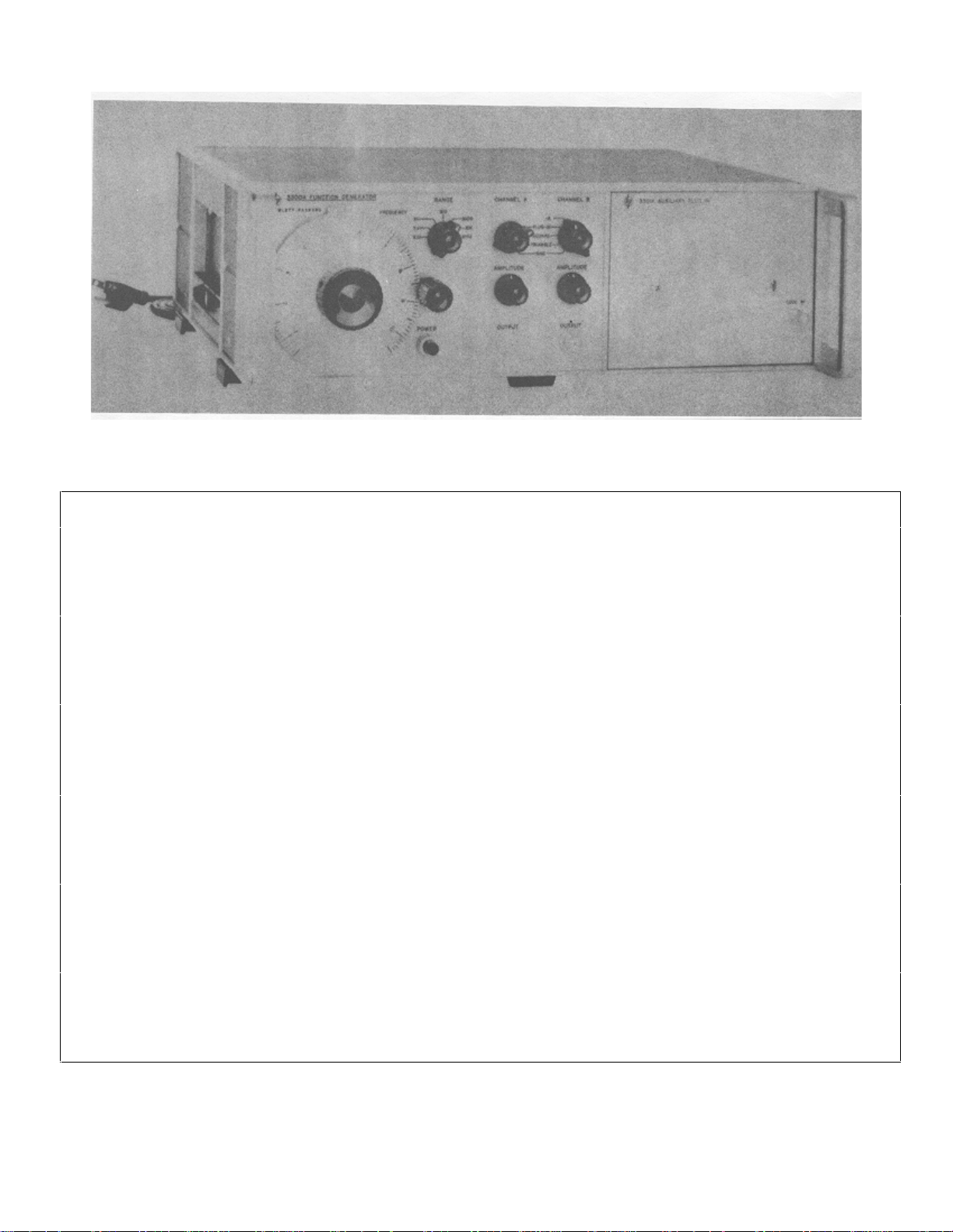
1-1. Model 3300A Function Generator..............1-0
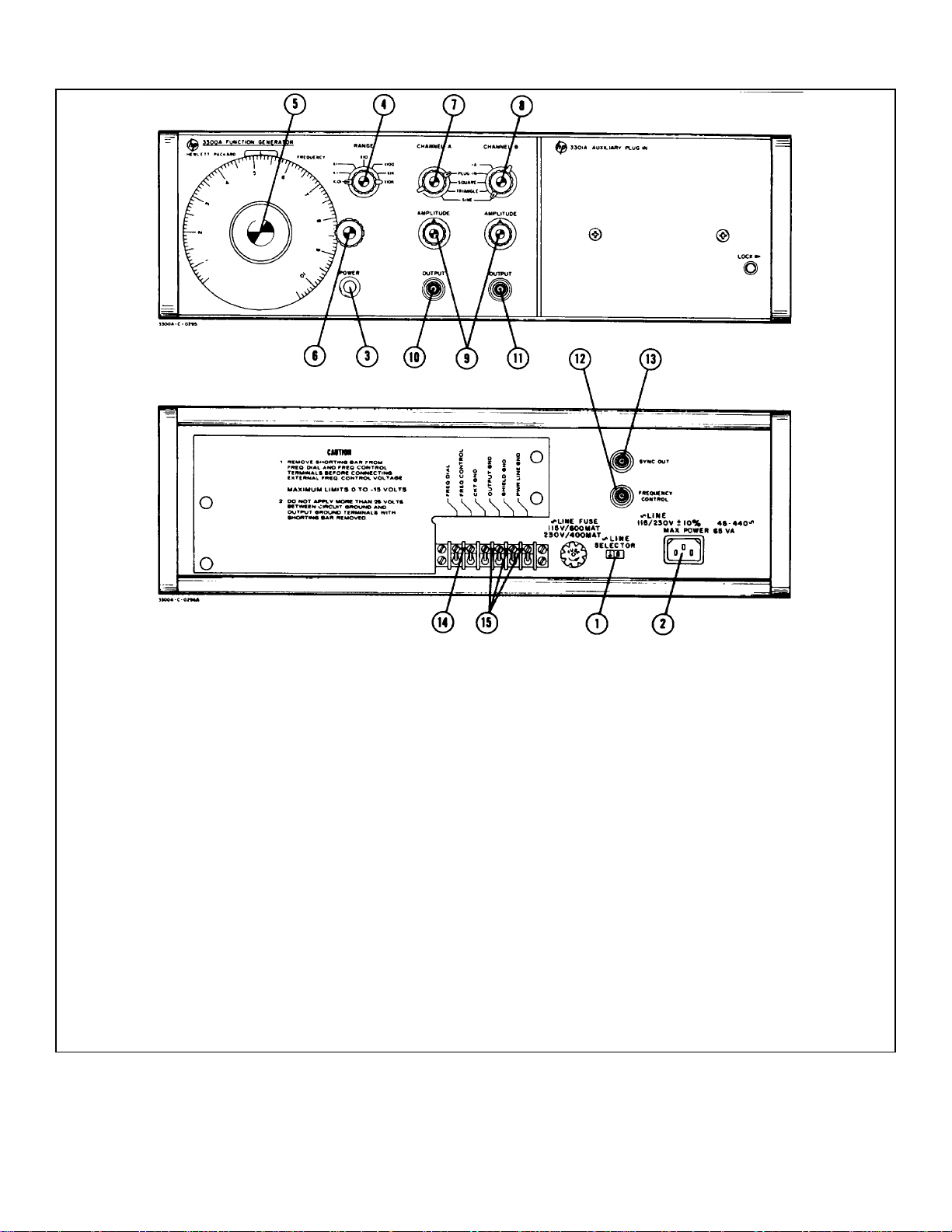
3-1. Description of Front and Rear Panel
Controls and Connectors.......................3-0
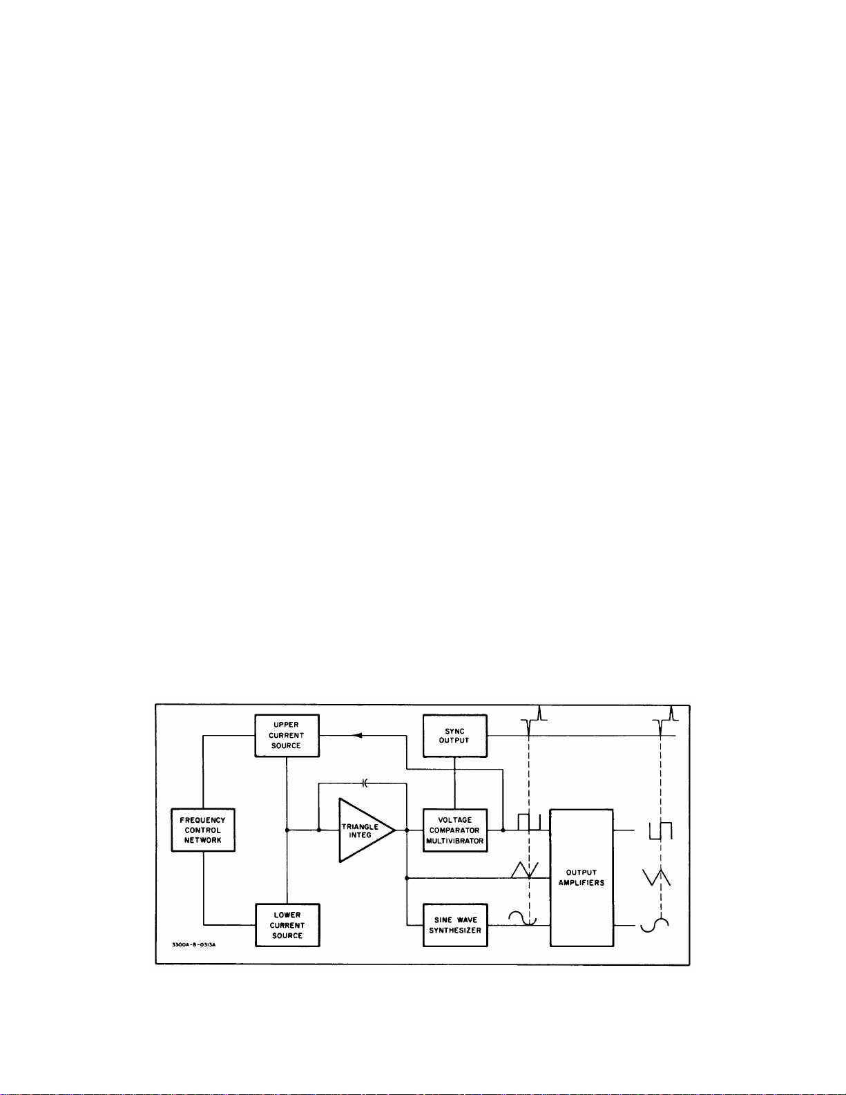
4-1. Block Diagram............................................4-1
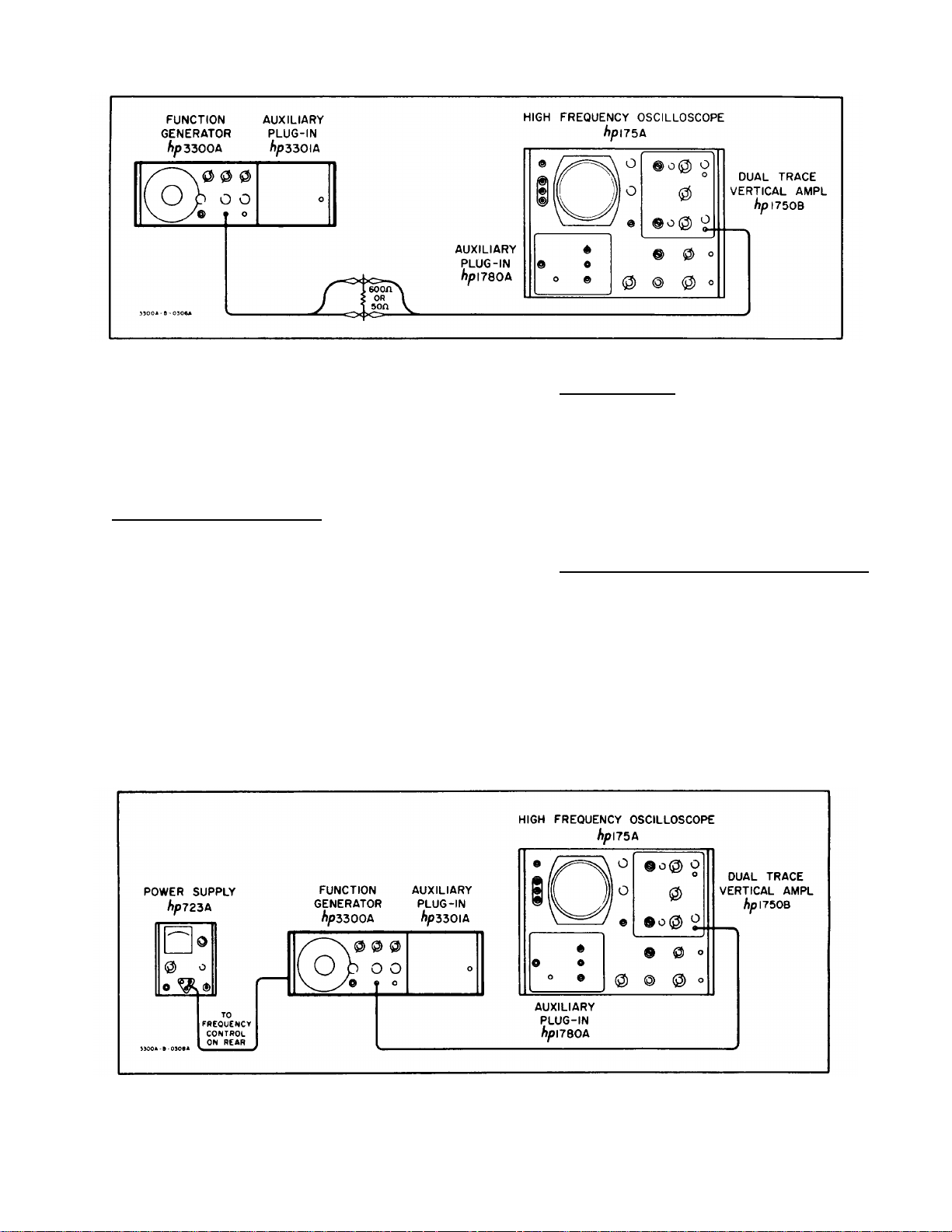
5-1. 600 ohm or 50 ohm Load Output Test
Setup.....................................................5-2
5-2. Remote Frequency Control Test Setup......5-2
5-3. Adjustment Point Location..........................5-4
5-4. Voltage Monitoring Points Top and
Bottom...................................................5-4
5-5. Symmetry Adjustment................................5-5
5-6. DC Output Level Adjust Test Setup ...........5-5
Number Page
5-7. Malfunction Isolating Plug.......................... 5-8
5-8. Troubleshooting Tree................................. 5-9
5-9. Normal Oscillator Wave Forms.................. 5-10
6-1. 3300A Top and Bottom Views ................... 6-2
6-2. Oscillator Circuit Schematic (A11, A13
and A14)................................................ 6-3
6-3. Range Switch Connections to Plug-In Unit 6-4
6-4. Output Amplifiers Schematic
(A15 and A16).................................... 6-5/6-6
6-5. Power Supply Schematic (A12 and A11) 6-7/6-8
6-6. J6 Plug-In Receptacle................................ 6-9
7-1. Modular Cabinet Parts............................... 7-0
iii
Page 7

TM 11-6625-2495-14&P
SECTION 0
INTRODUCTION
0-1. SCOPE.
This manual describes Gener ator, Signal SG-747/U ( HP-3300A) ( fig. 1-1) and provides m aintenanc e instruc tions.
Throughout this manual, SG-747/U is referred to as the Hewlett-Packard HP-3300A Function Generator.
0-2. INDEXES OF PUBLICATIONS.
a. DA Pam 310-4. Refer to the latest is sue of DA Pam 310-4 to determine whether there are new editions,
changes, or additional publications pertaining to the equipment.
b. DA Pam 310-7. Refer to DA Pam 310-7 to determine whether there are m odification work orders (MW O’s)
pertaining to the equipment.
0-3. FORMS AND RECORDS.
a. Reports of Maintenance and Unsatisfac tory Equipment. Maintenance form s, records, and reports which are
to be used by maintenance personnel at all levels of maintenance are listed in and prescribed by TM 38-750.
b. Report of Packaging and Handling Deficiencies. Fill out and f orward DD Form 6 (Packaging Improvem ent
Report) as prescribed in AR 735-11-2/NAVSUPINST 4440,127E/AFR 400-54/MCO 4430.3E and DSAR 4140.55.
c. Disc repancy in Shipment Report (DISREP) (SF 361). Fill out and forward Discrepancy in Shipment Report
(DISREP) (SF 361) as prescribed in AR 55-38/NAVSUPINST 4610.33B/AFR 75-18/MCO P4610.19C and DSAR 4500.15.
0-4. REPORTING OF EQUIPMENT IMPROVEMENT RECOMMENDATIONS (EIR).
EIRs will be prepared using DA Form 2407, Maintenance Request. Inst ruc tions f or pr eparing EIRs ar e provided in
TM 38-750, The Army Maintenance Management System. EIRs should be mailed directly to Commander, US Army
Communications and Electronics Materiel Readiness Command, ATTN: DRSEL-ME-MQ, Fort Monmouth, New Jersey
07703. A reply will be furnished directly to you.
0-5. ADMINISTRATIVE STORAGE.
Administrative storage of equipment issued to and used by Army activities shall be in acc or danc e with TM 740-90-
1.
0-6. DESTRUCTION OF ARMY ELECTRONICS MATERIEL.
Destruction of Army Electronics materiel to prevent enemy use shall be in accordance with TM 750-244-2.
0-1
Page 8
TM 11-6625-2494-14&P
Figure 1-1. Model 3300A Function Generator
Table 1-1. Specifications
AVAILABLE PLUG-IN UNITS: SINE WAVE DISTORTION: <1%. 0.01 Hz to 10
Model 3301A Auxiliary Plug-In. kHz; <3%, 10 kHz to 100kHz on the X10K range.
Model 3302A Trigger Plug-In.
Model 3304A Sweep/Offset Plug-In. SQUARE WAVE RESPONSE: <250 nsec rise and
Model 3305A Sweep Plug-In. fall time on all ranges; <500 nsec rise and fall
time in -A; <1% sag; <5% overshoot at full out-
OUTPUT WAVEFORMS: Sinusoidal, square, and put; <1% symmetry error.
triangle selected by panel switch. (Any two
outputs available simultaneously. TRIANGLE LINEARITY: <1% 0.01 Hz to 10 kHz;
<2%, 10 kHz to 100 kHz at full output; < 1%
FREQUENCY RANGE: 0.01 Hz to 100 kHz in symmetry error.
seven decade ranges.
SYNC PULSE OUTPUT: > 10 volts peak-to-peak
FREQUENCY RESPONSE: ± 1%, 0.01 Hz to 10
kHz; ± 3%, 10 kHz to 100 kHz on the X10K occurs at crest of sine and triangle wave.
range.
DIAL ACCURACY:. ± 1% of maximum dial setting amplitude over a period of 24 hours. (After 30
(1 minor division) 0. 01 Hz to 10 kHz; ±2% of minute warmup).
maximum dial setting (2 minor divisions) 10
kHz to 100 kHz. T. C. 0. 1%/°C. REMOTE FREQUENCY CONTROL: 0 to -10 volts
MAXIMUM OUTPUT PER CHANNEL: > 35 volts in a single range. Frequency resetability with
peak-to-peak open circuit; > 15 volts peak-to- respect to voltage ±1% of maximum frequency
peak into 600 ohms; > 2 volts peak-to-peak into on range selected.
50 ohms.
OUTPUT ATTENUATORS (both channels): 40 dB Less than 50 watts.
range.
OUTPUT IMPEDANCE: 600 ohms nominal (both (127 mm), 16" wide (406 mm), 11" deep
channels) ± 20%. (279 mm).
open circuit, <5 µsec duration. Sync pulse
DC STABILITY: Drift: <±0.25%6 of peak-to-peak
will linearly change frequency > 1 decade with-
POWER: 115 or 230 volts ±10%, 48 to 440 Hz.
DIMENSIONS: (inches and millimeters) 5" high
1-0
Page 9

Model 3300A Section I
SECTION I
GENERAL INFORMATION
1-1. GENERAL.
1-7. OUTPUT SYSTEM.
1-2. The Hewlett-Packard Model 3300A Function
Generator is a solid state instrument useful for most
general purpose frequency testing applications. Three
output waveforms are available from front panel
connectors; sine, square, and triangle. A sync pulse is
also available from a rear panel connector.
1-3. The -hp- Model 3300A Function Generator is a
type of relaxation oscillator. The triangle and square
wave voltage functions are inherent in the oscillatory
system. The sine wave is produced by synthesizing the
triangle wave.
1-4. The -hp- Model 3301A Auxiliary Plug-in or
another 3300A plug-in is required to provide internal
connection for basic unit (main frame) operation.
1-8. The -hp- Model 3300A has two completely
separate output channels. Each output is dc coupled
and can be fully floating with respect to power line
ground. An internal shield reduces radiated interf erence
and provides common mode rejection with floating
output. Separate connectors on the rear panel provide
terminals for circuit ground (
shield ground (
output ground may be floated from power line ground by
up to +250 volts. Any two of the three waveforms are
available simultaneously from the front panel connectors.
1-9. INSTRUMENT AND MANUAL
IDENTIFICATION.
), and power line ground ( ). The
), output ground ( ),
1-5. ELECTRONIC FREQUENCY CONTROL.
1-6. Frequency of the -hp- Model 3300A can be
controlled by either the front panel frequency dial or an
external voltage applied to a rear terminal connector.
This feature is useful for sweeping filters, amplifiers and
other frequency-dependent devices and for externally
programming frequencies for production testing. An
input voltage of approximately -0. 5 to -10 volts will
linearly control the frequency over any one range (one
decade).
If desired the frequency can be controlled over more
than one decade, by applying a +0.3 to -10 volts to the
FREQUENCY CONTROL BNC. A +0. 3 to -10 V input
will linearly control the frequency over approximately a
50:1 range.
1-10. Hewlett-Packard uses a two-section serial
number. The first section (prefix) identifies a series of
instruments. The last section (suffix) identifies a
particular instrument within this series. If a letter is
included with the serial number, it identifies the country in
which the instrument was manufactured.
1-11. If the serial prefix of your instrum ent differs f rom
the one on the title page of this manual, a change sheet
will be supplied to make this manual compatable with
newer instruments or the backdating information in
Appendix C will adapt this manual to earlier instr uments.
All correspondence with Hewlett-Packard s hould inc lude
the complete serial number.
1-1
Page 10

Model 3300A Section II
SECTION II
INSTALLATION
2-1. INTRODUCTION.
2-2. This section contains information and
instructions necessa ry for the installation and shipping of
the Model 3300A Function Generator. Included are initial
inspection procedures, power and grounding
requirements, installation information, and instructions
for repackaging for shipment.
2-3. INITIAL INSPECTION.
2-4. This instrument was carefully inspected both
mechanically and electrically before shipm ent. It should
be physically free of mars or scratches and in perfect
electrical order upon receipt. To confirm this, the
instrument should be inspected for physical damage in
transit. Also check f or supplied ac cessories and tes t the
electrical performance of the instrument using the
Performance Checks outlined in Section V.
2-5. POWER REQUIREMENTS.
2-6. The Model 3300A can be operated from any
source of 115 or 230 volts (* 109%), at 48 - 440 Hz.
With the instrument disconnected from the ac power
source, move the slide switch ( located on the rear panel)
until the desired line voltage appears. Power dissipation
is approximately 50 watts.
2-7. GROUNDING REOUIREMENTS.
2-8. To protect operating personnel, the National
Electrical Manufacturers’ Association (NEMA)
recommends that the Instrument panel and cabinet be
grounded. All Hewlett-Packard instruments are
equipped with a three -conductor power cable which,
when plugged into an appropriate receptacle, grounds
the instrument. The offset pin on the power cable threeprong connector is the ground wire.
2-9. To preserve the protection feature when
operating the instrument from a two-contact outlet, use a
three-prong to two-prong adapter and connect the green
pigtail on the adapter to ground.
2-10. INSTALLATION.
2-11. The Model 3300A is fully transistorized;
therefore, no special cooling is required. However, the
instrument should not be operated where the ambient
temperature exceeds 55°C (131F).
2-12. BENCH MOUNTING.
2-13. The Model 3300A is shipped with plastic feet and
tilt stand in place, ready for use as a bench instrument.
2-14. RACK MOUNTING.
2-15. The Model 3300A may be rack mounted by
using the 5" Rack Mount Kit (-hp- Part No. 5060-0775).
Instructions for the convers ion are included with the kit.
The rack mount for the Model 3300A is a standard width
of 19 inches.
2-16. REPACKAGING FOR SHIPMENT.
2-17. The following paragraphs contain a general
guide for repackaging of the instrument for shipment.
Refer to Paragraph 2-18 if the original container is to be
used: 2-19 if it is not. If you have any questions, contac t
your local -hp- Sales and Service Office. (See Appendix
B for office locations).
NOTE
If the instrument is to be shipped to
Hewlett-Packard for service or repair,
attach a tag to the instrument
identifying the owner and indicate the
service or repair to be accomplished;
include the model number and full
serial number of the instrument. In
any correspondence, identify the
instrument by model number, serial
number and serial number prefix.
2-18. If original container is to be used, proceed as
follows:
a. Place instrument in original container if
available. If original container is not available, one can
be purchased from your nearest -hp- Sales and Service
Office.
b. Ensure that container is well sealed with
strong tape or metal bands.
2-19. If original container is not to be us ed, proc eed as
follows:
a. Wrap instrument in heavy paper or plastic
before placing in an inner container.
b. Place packing material around all sides of
instrument and protect panel face with cardboard strips.
c. Place instrument and inner container in
heavy carton or wooden box and seal with strong tape or
metal bands.
d. Mark shipping container with "DELICATE
INSTRUMENT, " "FRAGILE", etc.
2-1
Page 11
Section II Model 3300A
(1) 115V/230V Slide Switch: S2 makes proper
connections in primary of input transformer for
selected input line voltage.
(2) Power Input Jack: J1, male receptacle for input
power cable.
(3) POWER Pushbutton: S1, a on-off switch which
illuminates when in the on position and power is
applied to the instrument.
(4) RANGE Switch: S3, a seven position rotary
switch which selects frequency determining
feedback parameters in the basic oscillatory
circuit.
(5) FREQUENCY Dial: R4, a linear dial which
controls frequency within the decade selected by
the RANGE Switch (4).
(6) Vernier Frequency Control: a fine frequency
adjustment knob.
(7) CHANNEL A Function Switch: S4, a four position
rotary switch which selects the desired OUTPUT
(10).
Figure 3-1. Description of Front and Rear Panel Controls and Connectors
(8) CHANNEL B Function Switch: S5, a five position
rotary switch which selects the desired OUTPUT
(11).
(9) AMPLITUDE Controls: R12 and R9 attenuators
which vary the output level of the respective
channels.
(10) and (11)
OUTPUT Connectors: J2 and J3, BNC jacks for
connection to the respective outputs of the
function generator.
(12) FREQUENCY CONTROL: J5, a BNC jack for
applying external frequency control voltage.
(13) SYNC OUT: J4, a BNC jack for connection to
sync pulse which occurs at the cres ts of the sine
and triangle wave.
(14) FREQ DIAL-FREQ CONTROL Shorting Bar:
completes the circuits to the FREQUENCY Dial
for internal frequency control.
(15) Common Grounding Straps: ties circuit, output,
and shield grounds to power-line ground. Should
be connected unless otherwise specified.
3-0
Page 12

Model 3300A Section III
SECTION III
OPERATING INSTRUCTIONS
3-1. INTRODUCTION.
3-2. This section consists of instructions and
information necess ary for the operation of the -hp- Model
3300A Function Generator.
3-3. CONTROLS AND INDICATORS.
3-4. Each operating control and connector located on
the 3300A is identified and described in Figure 3-1. The
description of each component is k eyed to an illustration
of that component.
3-5. TURN ON PROCEDURE.
NOTE
One of the plug-ins must be in place
and locked in before the 3300A is
turned on. To remove a plug-in, turn
off the 3300A and turn the LOCK knob
fully counter-clockwise. This unlocks
the plug-in and pushes it part way out
for ease of removal. To install a plugin, turn the LOCK knob fully counter clockwise and push into place in the
3300A until it hits the stop, then turn
the LOCK knob fully clockwise.
3-6. To turn on the Model 3300A, proceed as follows:
(Refer to Figure 3-1).
a. Set 115/230 V slide switch (1) to line voltage
to be used, and check f or proper value f use
(.6 amp slow-blow for 115 volt operation, .4
amp slow-blow for 230 volt operation).
b. Connect Power Input Jack (2) to the ac line
voltage with the power cord furnished with
instrument.
c. Depress POWER button (3); ensure that
light in button illuminates.
3-7. OPERATING INSTRUCTIONS.
NOTE
For small signal applications to obtain
optimum signal to noise performance,
use an external 20 dB attenuator.
3-8. To operate the Model 3300A locally using the
FREQUENCY dial, proceed as follows: (See Figure 3-1).
a. Select desired frequency by settings RANGE
Switch (4) and FREQUENCY Dial (5).
b. Select desired function by setting CHANNEL
A and/or CHANNEL B Function Switch (7) or
(8). PLUG-IN position is used for plug-in
function(s).
c. Set AMPLITUDE controls (9) for desired
output level at the OUTPUT connectors (10)
or (11).
3-9. To control the frequency of the Model 3300A
externally (remotely) proceed as follows:
a. Remove FREQ DIAL-to-FREQ CONTROL
shorting bar (14).
CAUTION
VOLTAGE APPLIED TO FREQ
CONTROL BNC SHOULD BE LIMITED
TO A VALUE BETWEEN +0.3 AND -15
VOLTS. VOLTAGES OUTSIDE THIS
RANGE WILL DAMAGE THE
INSTRUMENT.
b. Apply a negative dc voltage from -0.5 to -10
volts to the FREQUENCY CONTROL BNC
(12).
NOTE
-0.5 to -10 volts will linearly control the
frequency over one decade of range
selected. A +0.3 to -10 volts will
linearly control the frequency over
50:1 range.
c. Select desired frequency range and set
amplitude of externally applied voltage for
desired frequency.
d. All 3300A controls except the FREQUENCY
dial are operated in the same m anner as in
Paragraph 3-8.
3-10. To dc offset the output f unction of the 3300A with
either the 3301A or 3302A Plug-in, proceed as follows:
a. Remove CKT GND-to-OUTPUT GND
shorting bar (15).
CAUTION
DO NOT EXCEED ± 25 V DC OFFSET
VOLTAGE BETWEEN OUTPUT
GROUND AND CIRCUIT GROUND.
b. Connect the desired dc offset voltage, up to
3-1
Page 13

Section III Model 3300A
± 25 V, between CKT GND and the
common grounds. OUTPUT GND, SHIELD
GND, and PWR LINE GND should be
shorted together (15).
c. If more than ± 25 V dc offset is desired,
short CKT GND. OUTPUT GND, and
SHIELD GND together (15). Up to ± 250 V
dc may be applied between this common
ground and PWR LINE GND.
WARNING
WHEN THE OUTPUT GROUND IS
FLOATED ABOVE POWER LINE
GROUND. ALL BNC CONNECTORS
WILL BE AT THE OFFSET VO LTAGE.
3-2
Page 14
Model 3300A Section IV
SECTION IV
THEORY OF OPERATION
4-1. INTRODUCTION.
4-2. This section contains a des cription of the theory
of operation of the -hp- Model 3300A Function Generator
with the -hp- Model 3301A Auxiliary Plug-in.
4-3. GENERAL DESCRIPTION.
4-4. The Model 3300A contains a frequency control
network, two current sources, a triangle integrator, a
voltage comparator multivibr ator, a sine wave synthesizer
and output amplifiers. (Refer to Figure 4-1
4-5. The Model 3301A Auxiliary Plug-in provides
internal connections which facilitate Model 3300A
operation.
4-6. The voltage comparator multivibrator, current
sources and triangle integrator form the basic function
generating loop. The voltage comparator multivibrator
changes state at predetermined lim its on the positive and
negative slopes of the output of the triangular integrator.
This change of state shuts off the upper current source,
reverses the input to the triangle integrator. A cycle is as
follows: when the amplitude of the positive slope of the
triangle wave reaches the upper predetermined limit of
the voltage comparator multivibrator, the multivibrator
changes state. This change of state reverses the current
into the triangle integrator through control of the upper
current source which causes the output of the integrator
to decrease. The decrease continues until the amplitude
of the negative slope reaches the lower predetermined
limit. At this point, the voltage comparator multivibrator
changes state and again reverses the direction of current
at the input of the integrator and causes the output of the
integrator to rise. This rise continues until the voltage
comparator multivibrator again changes state thus
completing the cycle.
4-7. The frequency control network, governed
internally by the FREQUENCY Dial or externally through
the FREQUENCY CONTROL, determines the amount of
current in the current sources , which varies the frequenc y
as follows: an increase or decrease in input current
increases or decreases the slope of the triangle wave,
respectively. (A change in direction of input current
reverses the slope. ) Frequenc y will increase if the + and
- slopes are increased, as less tim e is required for the +
or - slope of the triangle wave to reach the pr edeterm ined
limits in the voltage comparator multivibrator.
4-8. The sine wave is synthesized from the triangle
wave by a nonlinear network. This network consists of
resistors and diodes biased so different diodes conduct
during different voltage levels of the tr iangle wave. These
diodes, when conducting, provide additional shunt paths
within the network. Each additional shunt path changes
the slope of the triangle wave so that the wave is shaped
to a sine wave.
4-9. The output amplifiers are dc coupled and fully
floating with respect to power line ground. CHANNEL A
and CHANNEL B amplifiers are identical and use a
differential amplifier at the input. To maintain the same
peak-to-peak amplitude regardless of function selected,
the overall closed loop gain of the amplifier is varied with
function selection.
Figure 4-1. Block Diagram
4-1
Page 15

Section IV Model 3300A
4-10. The sync pulse is produced by an RC
differentiating network. T he negative pulse at the output
is in phase with the positive crest of the sine and triangle
wave.
4-11. Power Supply (Refer to Figure 6-5) can operate
on either 115 or 230 volts input and delivers 3 pairs of
voltages, +40V, ±26.5V, and +
provides power for the oven heater. The 26.5 volt
supplies are regulated and the 20 volt supplies are double
regulated.
4-12. Critical temperature sensitive components are
housed within an oven in which the temperature is
maintained at approximately 800 C (1760 F).
4-13. SCHEMATIC THEORY.
4-14. FREQUENCY CONTROL NETWORK.
4-15. (Refer to Figure 6-2) T he FREQUENCY dial (R4)
in conjunction with the RANGE switch (S3) provides
internal frequency control. The basic frequency equation
can be expressed as F= i
where i is the current to the triangle integrator, C is the
triangle integrator feedback capacitor and e out is the
peak-to-peak voltage of the triangle wave.
4-16. The position of the RANGE switch determines the
integrating capacitor C. The FREQUENCY dial or
external control voltage determines the current i. The
frequency control voltage is applied to the current c ontrol
transistor Al IQ5, which establishes the am ount of curr ent
available to the triangle integrator from the current
sources AllQ6 and AllQ7.
4-17. CURRENT SOURCES.
4-18. The state of current source A11Q6 is controlled
by the voltage comparator multivibrator, and in turn,
controls the direction of the current in the input of the
triangle integrator. When A11Q6 is on, a current, 2 i,
flows through it and divides, i into the integrator and i
through current source A11Q7. When the bi-stable
multivibrator changes state and gates A11Q6 off, 2 i no
longer flows; however, the current through A11Q7
remains the same. Therefore, a current equal to i but
opposite in direction flows from the triangle integrator
input.
4-19. TRIANGLE INTEGRATOR.
4-20. The triangle integrator consis ts of an impedance
converter A11Q8 (a field effect transistor), a differential
amplifier A13Q1 and A13Q2, an em itter follower A13Q3,
diode A13CR1, and the capacitive feedback network : this
circuit integrates the constant current inputs into the
positive and negative slopes which mak e up the triangle
wave. The triangle wave is applied to the inputs of the
output amplifiers, sine wave synthesizer and voltage
comparator multivibrator.
4-21. VOLTAGE COMPARATOR MULTIVIBRATOR.
4-22. The voltage comparator multivibrator consists of
a voltage comparator switching network, A14Q8,
A14CR13 and A14CR14; a bi-stable multivibrator A14Q9
and Q10 and an emitter follower A14Q11. A14CR19 and
20V. The 40 volt supply
2C ∆ e out
R45 provide a low resistive path to ensure rapid rise and
fall time of the square wave in the event the capacitance
of the load is high. When the positive slope of the triangle
wave reaches +20 volts, A14CR13 is turned on. A14Q9
is then turned on which turns A14Q10 off. The rise in the
collector voltage of A14Q10 is coupled through emitter
follower A14Q11 and through A14CR20 and A14CR21
into the emitter circuit of A11Q6, and turns it on. The
output slope then becomes negative. A11Q6 rem ains on
until the negative slope reaches zero volts. At the zero
point on the negative slope A14CR14 is turned on which
causes the bi-stable multivibrator to c hange state so that
A14Q9 is now off and A14Q10 is on. The decrease in
A14Q10 collector voltage gates the current source,
A11Q6, off which reverses the integrator input current.
The positive slope then begins increasing toward the
upper limit, +20 volts. The output of the emitter follower is
differentiated by A14C7 and A14R48 to provide the sync
output. A negative sync pulse occurs at the crest of sine
and triangular wave, see Figure 4-1.
4-23. SINE WAVE SYNTHESIZER.
4-24. (See Figure 6-2) The sine wave synthesizer
comprises four control transis tors, the biased diodes with
associated voltage dividers, a differential amplifier
A14Q5, A14Q6 and the output amplifier A14Q7. A14R17
andA14R29 adjust the operating points of the voltage
dividers to minimize distortion. T he diodes are biased by
the four control transistors A14Q1 through A14Q4 and the
voltage dividers to provide twelve different current paths
in the input to the differential amplifier as the triangle
wave progresses. Each slope of the triangle wave is
modified in twelve steps so that the waveform appearing
at the base of A14Q5 approximates a sine wave. The
sine wave synthesizing network is isolated by the
differential amplifier A14Q5 and A14Q6 and amplifier
A14Q7.
4-25. OUTPUT AMPLIFIERS. Figure 6-4).
4-26. The etched circuit assemblies A15 and A16 are
identical. CHANNEL A and CHANNEL B differ due to the
-A output of CHANNEL B. The input for CHANNEL B with
its function switch in -A position, A16 Pin 5, is taken from
the junction of A15R20 and R21, XA15 Pin 11. The
output amplifiers are variable gain amplifiers. Gain is
varied by changing the amount of feedback for the
different functions. The following reference designators
should be prefixed by applicable assembly number . The
feedback is varied by resistors R1 through R5 and R23
C8 combination, to maintain equal peak-to-peak
amplitude of the various functions for a given
AMPLITUDE control setting. A differential amplifier, Q1
and Q2, make up the first stage f ollowed by two additional
amplifiers Q3 and Q4. The trim mer C2 in the feedback
network is used to shape the square wave. The
AMPLITUDE control provides a nom inal 600 ohms output
impedance, independent of amplitude control setting.
4-2
Page 16

Model 3300A Section IV
4-27. POWER SUPPLY (Figure 6-5).
4-28. The power supply consists of two full wave
rectifiers CR1 thru CR4 and four series regulated
supplies. AllCR1 provides a stable referenc e for the two
negative regulated supplies which in turn are the
references for the two positive regulated supplies. The
two 20 volt supplies are double regulated. The operation
of the four supplies is similar: A differential amplifier
senses and amplifies any change. The change is
applied through a driver stage to the series regulator
which then changes its conduction to oppose the
change.
4-29. Operation of the positive and negative supplies
is similar. Diodes CR2 thru CR5 and CR7 thru CR9
determine the maxim um current permitted to f low in the
series regulating transistors. Referring to Figure 6-5,
+26.5 volt supply, it can be seen that an increase in
current through R5 and R6 increases the overall for ward
bias on the diode network CR2 thru CR5. The
magnitude of this forward bias is determ ined by the sum
of the forward biased base-emitter diode voltage of Q1
and Q2 in addition to the voltage drop across the R5-R6
combination. When this forward bias increases to a level
sufficient to allow the diodes to conduct, any increas e in
the collector current of Q4 will pass through the diodes
and not enter the base of Q2. This, in thru, limits the
maximum current in the series regulating transistors.
4-30. OVEN.
4-31. (See Figure 6-5.) The desired oven temperature
is automatically maintained by a thermal control loop.
The loop consists of a thermistor, a signal amplifier, a
power amplifier, and the heater resistors. T he operation
of the loop is as follows: The resistance of RT1
(thermistor) decreases with an increase in temperature
which causes the base current of A11Q9 to increase.
The corresponding decrease of A11Q9 collector voltage
is coupled into the base circuit of the power amplifier Q7.
The collector current of Q7 then decreases which
decreases the current through the heater resistors
generating less heat and the temperature decreases.
The response of the loop is improved by the physical
location of A11R27 in close proximity to the thermistor.
4-3
Page 17

Section V Model 3300A
Table 5-1. Required Test Equipment
Instrument Type Required Characteristics Use Recommended Instrument
Electronic Counter Range: dc to 100 kHz Performance Checks, -hp- 5245L Electronic
Accuracy: 0.1% Adjustment and Counter with 5262A Plug-
Calibration in Time Interval Unit
Distortion Analyzer Range: 10 Hz to 100kHz Performance Checks -hp- Model 331A Distortion
Freq. Accuracy: +2% Analyzer
Sensitivity: 0.3%fullscale
Input: 1 volt rms
Oscilloscope Sensitivity: 50 mV/cm Performance Checks, -hp- 175A Oscilloscope
Bandwidth: dc to 30 MHz Adjustment with -hp- Plug-in 1750B
Calibration, Repair Vertical Amplifier
Probe 10:1 Bandwidth: dc to 30 MHz Performance Checks, -hp- 10001A Probe 10:1
Division Accuracy: ±2% Adjustment and
Calibration, Repair
DC Voltmeter Accuracy: + 1% F. S. Adjustment and -hp- 3440A Digital Volt-
Range: 10 mV to 50 V Calibration, Repair meter with Plug-in -hpInput Impedance: 10 M
Resistor 600 ohms Performance Checks -hp- Part No. 0730-0010
1/4 watt
+5%
Resistor 50 ohms Performance Checks -hp- Part No. 0683-5105
1/4 watt
+5%
Resistor 20 K Adjustment and -hp- Part No. 0686-2035
1/4 watt Calibration
+5%
Capacitor
Variable Line Voltage Range: 100 to 130 V Performance Checks Superior Type UCIM
Transformer
DC Power Supply Range: 0 - 10 volts, 500 mA Performance Checks, -hp- 723A Power Supply
AC Voltmeter Range:10 Hz to 4 MHz Adjustment and -hp- 400F/FL Voltmeter
Printed Circuit
Extender Board 15 Pin Repair -hp- Part No. 5060-0049
Printed Circuit
Extender Board 22 Pin Repair -hp- Part No. 5060-0630
1 µ F 50 V
30 mV to 300 V Calibration
full scale
Ω
Adjustment and -hp- Part No. 0160-0859
Calibration
Adjustment and
Calibration
Model 3443A
5-0
Page 18

Model 3300A Section V
SECTION V
MAINTENANCE
5-1. INTRODUCTION.
5-2. This section contains information necessary for
the proper maintenance of the -hp- Model 3300A
Function Generator. The required test equipment is
listed in Table 5-1. Test equipment with comparable
characteristics can be substituted if recommended
equipment is not available.
5-3. PERFORMANCE CHECKS.
5-4. The performance checks are front panel
procedures designed to com pare the -hp- Model 3300A
with its specifications. (See T able 1-1). These check s
may be accomplished with either the 3301A Auxiliary
Plug-in or Malfunction Isolating Aid Plug (see Figure 5- 7)
installed in the 3300A. These operations should be
completed before any attempt is made to adjust or
calibrate the instrument. Allow a 30 minute warm-up
period before making performance checks. If a
performance check indicates that the instrument does
not meet specifications refer to the applicable paragraph
in the Adjustment and Calibration procedure contained in
this Section. (See Table 5-5).
5-5. DIAL ACCURACY.
a. Test equipment required: Frequency
Counter (-hp- Model 5245L).
b. Connect CHANNEL A OUTPUT to the
frequency counter and set the 3300A
control as follows:
CHANNEL A function switch.........SINE
CHANNEL A AMPLITUDE............mid
position
c. Check frequency with dial at 1 and 10 for
each position of RANGE switch.
d. Accuracy should be * 1% of maximum dial
setting (one minor division) on X. 01
through X1K ranges, and ± 2% of
maximum dial setting (two minor divisions)
on X10K range.
5-6. Since the specification gives % of m aximum dial
setting (full scale, the accuracy will always be + 1 or 2
minor divisions at any point on the dial.
5-7. DISTORTION CHECK.
a. Test equipment required: Distortion
Analyzer (-hp- Model 331A).
b. Connect the OUTPUT of CHANNEL A to
distortion analyzer and set 3300A controls
as follows:
FREQUENCY dial......................10
RANGE switch............................X1K
CHANNEL A function switch......SINE
CHANNEL A AMPLITUDE
control.................................mid position
c. Distortion should be less than 1%.
Distortion should be less than 3%.
5-8. FREQUENCY RESPONSE:
5-9. Test equipment required: Oscilloscope (-hp-
Model 175/1750B).
5-10. MAXIMUM OUTPUT LEVEL, NO LOAD.
5-11. Repeat 5-10 above with CHANNEL A function
switch set to SINE and TRIANGLE. The m inim um peak to-peak voltage should remain 35 volts.
5-12. Repeat 5-10 and 5-11 on CHANNEL B.
5-13. MAXIMUM OUTPUT LEVEL, LOADED.
d. Position the RANGE switch to X10K.
NOTE
The sine function is electronically
synthesized from the triangle
function. Satisfactory performance of
Distortion Check assures symmetry
and triangle linearity.
a. Set up convenient reference level on
oscilloscope at 1 kHz.
b. Vary frequency over the entire range except
X10K. Amplitude should vary < ± 1%.
c. Vary frequency over the X10K range.
Amplitude should vary < + 3%.
a. Test equipment required: Os cillos c ope (- hp-
Model 175A/1750B).
b. Connect the OUTPUT of CHANNEL A to
Oscilloscope and set 3300A controls as
follows:
CHANNEL A function switch......SQUARE
CHANNEL A AMPLITUDE.........Max. CW
c. The peak-to peak voltage should be > 35
volts over entire frequency range.
a. Test equipment required: Os cillos c ope (- hp-
Model 175A/1750B), 600 ohm, and 50 ohm
resistor, see Table 5-1.
b. Connect OUTPUT of CHANNEL A and 600
ohm resistor as shown in Figure 5-1. Set
the 3300A controls as follows:
FREQUENCY dial...................10
RANGE switch ........................X100
CHANNEL A AMPLITUDE......
control.............................Max. CW
CHANNEL A function switch...SQUARE
c. Peak-to-peak voltage should be > 15 volts.
5-1
Page 19
Section V Model 3300A
Figure 5-1. 600 ohm or 50 ohm Load Output Test Setup
5-14. Repeat 5-13 on CHANNEL B. Limit should
remain > 15 volts peak-to-peak.
5-15. Repeat 5-13 and 5-14 except load the
instrument with the 50 ohm resis tor. CHANNEL A and
CHANNEL B voltage output should be > 2 volts peak -topeak.
5-16. SQUARE WAVE RESPONSE.
a. Test equipment required: Os cillos c ope (- hp-
Model 175A/1750B) and 10:1 Probe (-hpModel 10001A).
b. Connect CHANNEL A OUTPUT without a
load to the oscilloscope using the 10:1
Probe, and set the 3300A controls as
follows:
CHANNEL A function.................SQUARE
FREQUENCY dial......................10
RANGE switch............................X10K
c. Verify: Rise and fall time <250 nano sec.
Sag <1%
Overshoot (full output) <5%
Symmetry error <1%
5-17 Repeat 5-16 on CHANNEL B.
5-18. SYNC OUTPUT.
a. Test equipment required: Os cillos c ope (- hp-
Model 175A/1750B) and 10:1 Probe (-hpModel 10001A).
b. Connect SYNC OUTPUT to oscilloscope
and set 3300A controls as follows:
FREQUENCY dial......................10
RANGE switch ...........................X1K
c. Pulse should be > 10 volts peak-to-peak
and < 5 microsecond duration.
5-19. REMOTE FREQUENCY CONTROL CHECK.
a. Test equipment required: DC Power Supply
(-hp- Model 723A) and Oscilloscope (-hp-
Model 175A/1750B).
CAUTION
VOLTAGE APPLIED TO FREQUENCY
CONTROL BNC SHOULD BE LIMIT ED
TO A VALUE BETWEEN 0 AND
NEGATIVE 15 VOLTS. VOLTAGES
OUTSIDE THIS RANGE WILL
DAMAGE THE INSTRUMENT.
Figure 5-2. Remote Frequency Control Test Setup
5-2
Page 20

Model 3300A Section V
b. Connect the instruments as shown in Figure
5-2. Remove FREQ. DIAL-to-FREQ.
CONTROL shorting bar.
c. Set 3300A controls as follows:
CHANNEL A function switch......SINE
RANGE switch............................X10
CHANNEL A AMPLITUDE.........Max. CW
d. Monitor frequency as power supply is varied
from 0 to -10 volts. Frequency should vary
over the decade, 10 to 100 cycles.
5-20. CHANNEL B-A CHECK.
a. Test equipment required: Os cillos c ope (- hp-
Model 175A/1750B).
b. Connect CHANNEL A OUTPUT to one
channel of the oscilloscope and CHANNEL
B OUTPUT to the other channel of the
oscilloscope.
c. Set 3300A controls as follows:
CHANNEL A function switch......SINE
CHANNEL B function switch......-A
d. The output of CHANNEL B should be a sine
wave, but 1800 out of phase with the output
of CHANNEL A.
5-21. ADJUSTMENT AND CALIBRATION.
5-22. COVER REMOVAL.
When it is necessary to repair or adjust the Model
3300A, one or more covers will have to be removed. To
remove either the top or bottom c over, remove the two
phillips screws and slide the cover to the rear.
NOTE
Allow a 30-minute warm-up period
before making any adjustments.
5-23. POWER SUPPLY ADJUSTMENTS.
5-24. The adjustment and calibration procedures are
designed to adjust and calibrate the -hp- Model 3300A
and should be undertaken only if the performance
checks indicate the instrument does not meet
specifications. (See Figure 5-3 for adjustment
identification and indication.)
5-25. The measurement points, adjustments and
voltage limits are given in Table 5-2. Refer to Figure 5- 4
for convenient top and bottom chassis location for
monitoring supply voltage. Supplies should be adjusted
in the following order: -26. 5V, +26.5 V, -20 V, +20 V.
The supplies should be rechecked and, if necessary,
readjusted in the same order.
5-26. POWER SUPPLY RIPPLE CHECK.
5-27. POWER SUPPLY REGULATION CHECK.
5-28. OVEN REGULATION.
5-29. FREQUENCY SYMMETRY ADJUST.
5-30. Lower Frequency Symmetry Adj. (A13R22).
a. Test equipment required: AC Voltmeter (-
hp- Model 400F/FL).
b. With the AC Voltm eter, check the regulated
power supplies (i26. 5 V and +20.00 V) for
ripple.
c. Ripple should be < 20 millivolts.
a. Test equipment required: DC Voltmeter (-
hp- Model 3440A/3443A) and Variable Line
Voltage Transformer.
b. Apply power to the 3300Athroughthe
variable line voltage transformer.
c. With the DC Voltmeter, check the regulated
power supplies as input voltage to the
3300A is varied from 103 to 127 Vac (207
to 253 Vac). Voltage limits are given in
Table 5-2.
a. After 3300A has been on approxim ately 30
min, connect a DC Voltmeter between
circuit ground and collector of Q7 (Q9 on
instruments Serial prefixed: 519-, 533-,
609-, 616- and 622-.) Voltage noted s hould
be approximately 20 volts.
NOTE
This voltage will vary with oven
amplifier transistors.
b. Turn 3300A off for approximately 1 minute,
then turn it on. Voltage should have
decreased to approximately 15 volts.
Voltage should then increase and
overshoot that noted in step a but in time
damp out to approximately 20 V.
a. Test equipment required: Electronic
Counter (-hp- Model 5245L with 5262A
Time Interval Plug-in).
b. Set 3300A controls as follows:
RANGE Switch...........................X.1
CHANNEL A Function................SQUARE
Output Attenuation.....................Max. CW
FREQUENCY dial......................1
Table 5-2. Power Supply Adjustments
POWER MEASUREMENT ADJUSTMENTS VOLTAGE
SUPPLY POINT LIMITS
+40 ANY RED WIRE (except on S2) NONE +40±3 V
-40 ANY VIOLET WIRE NONE -40±3 V
-26.5 ANY WHITE/VIOLET WIRE A12R20 -26.5 ± 02 V
+26.5 ANY WHITE/RED WIRE A12R7 +26.5 + .02 V
-20 ANY WHITE/BLACK/VIOLET WIRE A12R26 -20.00+0.01 V
+20 ANY WHITE/BLACK/RED WIRE A12R25 +20.00+. 01 V
5-3
Page 21

Section V Model 3300A
Figure 5-3. Adjustment Point Location
Figure 5-4. Voltage Monitoring Points Top and Bottom
5-4
Page 22

Model 3300A Section V
RANGE switch ...........................X10
FREQUENCY dial......................10
CHANNEL A function.................SINE
c. Output frequency should be 100 Hz, *1
minor division on FREQUENCY dial.
d. Position RANGE switch to X. 1 and
measure output frequency (1 Hz *1 minor
division on FREQUENCY dial.
NOTE
Figure 5-5. Symmetry Adjustment
c. Measure t1 and adjust A13R22, LOWER
FREQ. SYM., to made t2 = t1. Ref. Figure
5-5. If A13R22 does not have enough
range change A13Q20.
5-31. Upper Frequency Symmetry Adjust.
(A13R23).
NOTE
Lower Frequency Symmetry must be
set before this adjustment is made.
a. With the same setup as used for the Lower
Symmetry Adjust, select X100 RANGE and
adjust A13R23 to make t2 equal to t1. The
symmetry error should be < 1%.
b. Check the symmetry with the dial set to 3
and then again with the dial set to 10. The
symmetry error at both dial settings should
be <1%.
% Symmetry error = t1 -t2 X 100
t1 -t2
5-32. CURRENT SOURCE ADJUST (A13R24).
NOTE
This adjustment interacts with the
Frequency Symmetry Adjustments
(A13R22 and A13R23): perform the
following adjustment only if the
frequency is not within specified
accuracy(Table 1-1) on the X10 orX.1
RANGE.
a. Test equipment required: Frequency
Counter (-hp- Model 5245L).
b. Connect CHANNEL A OUTPUT to
Frequency Counter, and set 3300A controls
as follows:
5-33. DIAL ADJUSTMENT.
5-34. DIAL CALUBRATE.
5-35. FREQUENCY CALIBRATION ADJUST.
5-36. X1K RANGE ADJUST (A13C19).
Repeat Frequency Symmetry Adjust
outlined in paragraph 5-29 if A13R24
is adjusted in the following step.
e. If the frequency is not within specifications
given in step c or d, adjust A13R24
CURRENT SOURCE ADJ for optimum
indication on both X10 and X. I RANGE.
a. Test equipment required: Frequency
Counter (-hp- Model 5245L).
b. Connect CHANNEL A OUTPUT to
Frequency Counter, and set 3300A control
as follows:
RANGE switch ...........................X10
CHANNEL A function.................SINE
c. Loosen dial from hub and adjust the
frequency of 3300A to exactly 100 cps by
rotating the hub. Set the dial to read "1"
and tighten the dial to the hub. Recheck
the frequency.
(A13R17).
a. With same setup as used for 5-33, turn
FREQUENCY dial to "10".
b. Adjust A13RI7 FREQ CAL ADJ for output
frequency of 1 kHz.
a. With same setup as used for 5-33, set
RANGE switch to X1K and FREQUENCY
dial to "10".
Figure 5-6. DC Output Level Adjust Test Setup
5-5
Page 23

Section V Model 3300A
b. Adjust A13C19 X1K RANGE ADJ for output
frequency of 10 kHz.
5-37. X10K RANGE ADJUST (A13C6).
a. With same setup as used for 5-33 set
RANGE switch to X1OK and FREQUENCY
dial to "10".
b. Adjust A3C6, 100 kHz Dial calibrate adjust
for an output frequency of 100 kHz.
5-38. DISTORTION ADJUST (A14R17 AND A14R29).
a. Test equipment required: Distortion
Analyzer (-hp- Model 331A.)
b. Connect CHANNEL A OUTPUT to
distortion analyzer and set Model 3300A
controls as follows:
FREQUENCY dial......................1
RANGE switch............................X1K
CHANNEL A function.................SINE
c. Adjust A14R17, UPPER SINE ADJ and
A14R29 LOWER SINE ADJ for minimum
distortion.
d. Distortion should be < 1%.
5-39. DC OUTPUT LEVEL ADJUST (A15R7 AND
A16R7).
a. Test equipment required: DC Voltmeter (-
hp- Model 3440A) and RC Filter see Figure
5-6, page 5-5.
b. Connect CHANNEL A OUTPUT to DC
Voltmeter through a filter as shown in
Figure 5-6.
c. Set 3300A controls as follows:
RANGE switch............................X100
FREQUENCY dial......................10
CHANNEL A Function................Vary
CHANNEL A AMPLITUDE.........Max. CW
d. Check dc output level on all three functions .
Adjust A15R7 DC LEVEL ADJ for minim um
voltage on all functions. DC levels should
be +200 mV.
NOTE
Compromise the adjustment of
A15R7 so that all functions are as
close to zero volts as possible.
5-40. Repeat 5-39 on CHANNEL B, and adjust
A16R7 DC LEVEL ADJ.
5-41. SQUARE WAVE ADJUST (A15C2 AND
A16C2).
a. Test equipment required: Os cillos c ope (- hp-
Model 175A) and 10:1 Probe. (-hp- Model
10001A).
b. Connect the CHANNEL A OUTPUT to the
oscilloscope using the 10:1 Probe.
c. Set 3300A controls as follows:
CHANNEL A function.................SQUARE
FREQUENCY dial......................10
RANGE switch ...........................X10K
d. Adjust A15C2 SQUARE WAVE ADJ for
minimum rise time with less than 5%
overshoot on the square wave. Rise tim e
should be < 250 n sec.
5-42. Repeat 5-41 on CHANNEL B, and adjust
A16C2 SQUARE WAVE ADJ.
5-43. REPAIR PROCEDURES.
5-44. SERVICING ETCHED CIRCUIT BOARDS.
5-45. The Model 3300A has six etc hed circuit boards.
Use caution when removing them to avoid damaging
mounted components. The -hp- Part No. for the
assembly is marked on the circuit board to identif y it and
on the appropriate schematic. Refer to Section VII for
replacement -hp- Part No’s. The etched circuit boards
are of the plated-through type. The electr ical connec tion
between the two sides of the board is made by a layer of
metal plated-through the component hole. When
working on these boards, observe the following rules:
a. Use a low-heat (25 to 30 watts) small-tip
soldering iron, and a small diameter rosin
core solder.
b. Remove circuit components by placing the
soldering iron on the component lead on
either side of the board, and pulling up on
the lead.
If a component is obviously damaged, clip
leads off as close to the component as
possible and then remove leads with a
soldering iron.
CAUTION
EXCESSIVE HEAT CAN CAUSE THE
CIRCUIT AND BOARD TO SEPARATE,
OR CAUSE DAMAGE TO THE
COMPONENTS.
c. Clean com ponent lead hole by heating the
hole with the iron and inserting a wooden
toothpick. Remove the toothpick after the
solder has cooled and insert the new
component lead.
d. Shape the new components leads and
insert them in lead holes. Reheat with
soldering iron and add a small amount of
new solder as required to insure a good
electrical connection.
e. Clean excessive flux from the connection
and adjoining area.
5-6
Page 24

Model 3300A Section V
CAUTION
TO AVOID SURFACE
CONTAMINATION OF THE PRINTED
CIRCUIT, CLEAN WITH A WEAK
SOLUTION OF WARM WATER AND
MILD DETERGENT AFTER REPAIR.
RINSE THOROUGHLY WITH CLEAN
WATER AND ALLOW IT TO DRY
COMPLETELY BEFORE OPERATING.
DO NOT USE ALCOHOL OR ANY
OTHER CLEANING SOLUTION
EXCEPT DETERGENT AND WATER.
DO NOT APPLY ANY COMMERCIAL
MOISTURE SEALING SPRAY TO T HE
BOARDS. APPLICATION OF THESE
AGENTS WILL CAUSE LEAKAGE
PATHS AND SUBSEQUENTLY,
DETERIORATION TO THE
OPERATION OF THE INSTRUMENT.
f. Wear c lean, lint f r ee cotton or rubber gloves
when handling the circuit boards. Avoid
touching the board or components with
bare fingers as skin oils can cause
contamination and leakage paths.
5-46. SERVICING ROTARY SWITCHES.
5-47. The 3300A has three rotary type switches;
RANGE, CHANNEL A, and CHANNEL B. When working
on these switches, observe the following rules:
a. Use a low-heat (25 to 50 watts) small tip
soldering iron, and a small diameter rosin
core solder.
b. When replacing components, attempt to
dress them as nearly to their original
alignment as possible.
c. Clean excessive flux from the connection
and adjoining area.
5-48. REPLACEMENT OF FACTORY SELECTED
COMPONENTS.
5-49. Replacement components are identified in Table
5-3 and 5-6. Should it become necess ary to replace any
of the capacitors in the feedback circuit of the Triangle
Integrator, the replacement capacitor (a good quality
polycarbonate or mica film type) must be selected so that
the approximate parallel capacitance is as indicated in
Table 5-3. If after capacitor replacement, the resultant
frequency is not correct, the necessary capacitor change
can be determined by the following formula:
C
correction = C feedback
(Freq - desired Freq X100
desired Freq
Example: X1K range inaccurate
Freq of 9.8 kHz (Range X1K dial 10)
C
correction = 0.011 µF
(9.8K - 10K) X100
10K
= -0.011 µF = -.00137 µF
8
5-50. TROUBLESHOOTING PROCEDURE.
5-51. This section contains procedures designed to
assist in the isolation of a malfunction. These
procedures are based on a systematic analysis of the
instrument in an effort to localize the problem. These
operations should be undertaken only after it has been
established that the difficulty cannot be eliminated by the
adjustment and calibration procedures outlined in
Paragraph 5-21.
5-52. Conduct a visual check of the 3300A for poss ible
burned or loose components, loos e connections, or any
other obvious condition which might be a source of
trouble. An investigation should also be made to ensure
that the trouble is not a result of conditions external to
the 3300A.
5-53. The checks outlined in this section are not
designed to measure all circuit parameters, rather only to
localize the malfunction. Ther efore, it is highly probable
that additional checks and measurements will be
required to completely isolate the faulty component.
Amplifier gain may also vary slightly between
instruments; therefore, it is not necessary to precisely
duplicate waveforms or voltages described.
5-54. MALFUNCTION ISOLATION PLUG.
5-55. A malfunction isolating tool can be fabr icated for
isolating a malfunction to the 3300A or the plug-in unit. A
50 pin connector -hp- Part No. 1251-0099 can be fitted
with 4 jumpers (see Figure 5-7 for
Table 5-3. Integrator Feedback Capacitance
DESIGNATED CAPACITORS PADDING CAPACITORS RANGE VALUE
C3 C16, C17, and possible C18 X.01, X1
A13C13 C14 and C15 X.1, X10
A13C10 C11 and C12 X100
A13C7 C8 and C9 X1K
A13C6 C5 X10K
5-7
11 µF
1.1 µF
0.11 µF
0.011 µF
0.0011 µF
Page 25

Section V Model 3300A
jumper location). If 3300A oper ation is normal with this
plug mated with J6, the trouble is in the plug-in unit.
Figure 5-7. Malfunction Isolating Plug
5-56. PRECAUTIONS.
5-57. In the event the -20 volt supply is inoperative, the
oven heater should be disabled while troubleshooting. A
point to disable the oven is to disconnect the smaller
diameter red wire (26 gage) from XA12 Pin 1. The larger
Table 5-4. Troubleshooting Aid
SYMPTOM POSSIBLE CAUSE
No output either channel. Power Lamp lit. Use Figure 5-8 Troubleshooting Tree.
Output on only one channel. Check applicable amplifier board A15
Frequency incorrect. Specific range. Check feedback capacitor of effected
Two of the three functions normal, only Check input resistor of missing function;
one channel effected. on amplifier assembly; for example, no
Frequency and symmetry incorrect at Check oven heating voltage J6 pin 42
low end of dial, all ranges. 20 volts.
Frequency will not vary with FREQ dial. Check Freq shorting bar rear chassis;
No sync output. Check A14C7, A14R46 and A14R48.
Power supply voltage incorrect. Begin troubleshooting by substituting a
Frequency out of tolerance on 1 or 2 Change A11Q8. Use caution in soldering
ranges which are not adjacent. and use a clip-on heat sink.
Distortion at 100 kHz. Check A13Q1.
Dc level off on square wave. Check A14CR18 for open.
Symmetry erratic at low frequencies. Check A14Q8.
Lower half of sine wave clipped on one Check A15Q5 or A16Q5.
channel only.
Will not oscillate. Check Triangle Integrator A13Q1 thru
diameter redwire (22 gage) should be left connected to
XA12 Pin 1. W hen the -20 volt power supply is lef t out,
the oven remains in full heat condition. Thermal fuse
A11F1 will melt and open if this heat condition exists for
any extended period.
5-58. When troubleshooting Power Supply Assembly,
remove the Output Amplifier Assemblies A15 and A16.
5-59. TROUBLESHOOTING TREE.
5-60. In the event of a malfunction which causes the
oscillatory system to cease functioning; the output of the
triangle integrator emitter follower would most likely
stabilize at either one of voltages as indicated in Figure
5-8. Approximately +25 volts is the upper limit of the
positive slope, and -2.5 volts is the lower
CHANNEL A or A16 CHANNEL B.
range on Triangle Integrator A12; for
example, Range X100 check C10, C11,
and C12.
SINE on CHANNEL A. Check A15R1.
A11Q5 and associated circuit parameters.
well-regulated 12.1 volt source for A11CR1.
Remove Output Amplifiers when troubleshooting Power Supply.
A13Q3.
5-8
Page 26

Model 3300A Section V
Table 5-4. Troubleshooting Aid (Cont'd)
SYMPTOM POSSIBLE CAUSE
Half of sine wave clipped on both channels. Check A14Q5 and A14Q7.
The synthesizer waveform is symmetrical about 10 volts at the base of
A14Q5 and at the corresponding junctions along the voltage divider
R10 to R15 and R25 to R20.
Loss of square wave symmetry at lowest
range.
No oscillation on X.1 and X.01 RANGE; dial
at 1.
+20 volts ok when oven cold, high when
oven hot.
Slow symmetry drift. Check A14CR21, A14CR20, A11Q6, A11Q7.
Inoperative oven, open thermal fuse.
Check A11Q8.
Check A11Q1, A11Q2.
Figure 5-8. Troubleshooting Tree
5-9
Page 27

Model 3300A Section V
limit of the negative slope out of the integrator circuit.
The condition of the other major circuits in the basic
oscillating loop, the Voltage Comparator Bi-stable
Multivibrator and current source, can, in most instances,
be used to isolate the malfunction to a given circuit as
outlined in Figure 5-8. The term normal, as applied to
the results obtained at the different points tested, refers
to the output at that point which would reverse the slope
at the output of the triangle integrator and sustain
oscillation. Abnormal refers to that output which would
produce the same slope and prevent oscillation.
5-61. Figure 5-9 contains the normal voltages and
waveforms which should be present at the points
indicated. Voltage levels are approximate and may vary
from instrument to instrument due to differences in
transistors.
5-62. TROUBLESHOOTING TABLES.
5-63. Table 5-4 gives additional information to assist
in the isolation of a malfunction. Symptoms and
possible causes are listed. Table 5-5, Maintenance
Correlation Table, lists various 3300A functions and
gives the corresponding performance checks and
adjustments.
Figure 5-9. Normal Oscillator Wave Forms
Table 5-5. Maintenance Correlation Table
ADJUSTMENT AND
FUNCTION PERFORMANCE CHECK CALIBRATION TROUBLESHOOTING
Dial Accuracy Paragraph 5-5 Paragraph 5-34 thru 5-37 Para. 5-23, All assy
Distortion Paragraph 5-7 Paragraphs 5-38, 5-30 and Oven, All assembly
5-31
Output Paragraph 5-10thru 5-15 Paragraphs 5-39 thru 5-42 A15 or A16 assembly
Q5 thru Q8
Square Wave Paragraph 5-16 and 5-17 Paragraph 5-41 and 5-42 Isolate trouble to
specific board or
chassis by interchanging A15 and A16 boards.
Sync Output Paragraph 5-18 None A14C7, A14R46 and
A14R48
Remote Freq control Paragraph 5-19 None J6 or plug-in pins 32, 7
Channel B-A Check Paragraph 5-20 None Continuity A15 pin 11
to S5AF pin 5, 11, to 16R5
Power Supplies None Table 5-2 Remove PC boards; see
Figure 5-4 para. 5-55;Check A12
components
5-10
Page 28

Model 3300A Section V
Table 5-5. Maintenance Correlation Table (Cont’d)
ADJUSTMENT AND
FUNCTION PERFORMANCE CHECK CALIBRATION TROUBLESHOOTING
DC Output None Paragraph 5-39 and 5-40 Change A15 or A16 Q1
and/or Q2, if all functions
negative increase value of
R10* not to exceed 3K
Oven Regulation Paragraph 5-28 None Oven temperature should be
70 to 80ºC Check Q7, chec k
+ 40 volt line
Table 5-6. Factory Selected Components
VALUE
DESIGNATOR FUNCTION LOW NORMAL HIGH
A11R11 Adjust frequency error between X.01 and X1 range or X.1
and X10 range
A11R17 Adjust oven temp to between 70º and 80ºC 8.2K 8.87K 9.09K
A13C5 Adjust 10 on dial on X10K range *
A13C9 Adjust 10 on dial on X1K range *
A13C12 Adjust 10 on dial on X100 range *
A13C15 Adjust 10 on dial on X10 and X0.1 range *
A13C18 Adjust 10 on dial on X1 and X0.01 range *
A13R9 Reduce switching transients --- 15 --A13R18
A13R19
A13R20 Center R22, lower freq sym 3 5760 No limit
A14R46 Adjust dc output level for less than 200 mV --- 47 56
A15C1 and
A16C1
A15C4 and
A16C4
A15C9 and
A16C9
A15R3 and
A16R3
A15R10 and
A16R10
Center R23, upper freq sym 0 49.9 ---
Prevent oscillation --- 200pF ---
Reduce switching transients 12pF 39pF 56pF
Reduce switching transients 39pF 59pF 68pF
Adjust square wave dc level --- 5360 ---
Adjust dc output level 2200 3300 3600
--- 130K ---
*See Table 5-3 for value selection.
5-11
Page 29

PERFORMANCE CHECK TEST CARD
Hewlett-Packard Model 3300A Test Performed by ______________________________
Function Generator Date ______________________________
Serial No. __________
CHECK DESCRIPTION SPECIFICATION INDICATION
1. Dial Accuracy
1 x .01 between 90.9 and 111.1 sec _______
10 x .01 between 9.90 and 10.1 sec _______
1 x .1 between 9.09 and 11.1 sec _______
10 x .1 between 990 and 1010 ms _______
1 x 1 between 909 and 1111 ms _______
10 x 1 between 99.0 and 101.0 ms _______
1 x 10 between 90.9 and 1111 ms _______
10 x 10 between 99 Hz and 101 Hz _______
1 x 100 between 90 Hz and 110 Hz _______
10 x 100 between .99 kHz and 1.01 kHz _______
1 x 1K between .9 kHz and 1.1 kHz _______
10 x 1K between 9.9 kHz and 10.1 kHz _______
1 x 10K between 8 kHz and 12 kHz _______
10 x 10K between 98 kHz and 102 kHz _______
2. Distortion
X1K Range < 1% _______
X10K Range < 3% _______
3. Frequency Response
X.01 thru X1K Range < 1% _______
X10K Range < 3% _______
4. Maximum Output Level
No load Channel A > 35 V p-p _______
No load Channel B > 35 V p-p _______
600ê load Channel A > 16 V p-p _______
600ê load Channel B > 16 V p-p _______
50ê load Channel A > 2 V p-p _______
50ê load Channel B > 2 V p-p _______
5. Square Wave Response
a. Channel A
Rise time < 250 ns _______
Fall time < 250 ns _______
Sag < 1% _______
Overshoot < 5% _______
Symmetry < 1% _______
b. Channel B
Rise time < 250 ns _______
Fall time < 250 ns _______
Sag < 1% _______
Overshoot <5% _______
Symmetry < 1% _______
6. Sync Output
Amplitude > 10 V p-p _______
Duration
7. Remote Frequency
Control Check vary from 10 to 100 Hz _______
8. -A Output
Channel B 180º shift _______
< 5µs
_______
5-12
Page 30

Model 3300A Section VI
SECTION VI
CIRCUIT DIAGRAMS
6-1. INTRODUCTION.
6-2. This section contains schematics and
component location diagrams for the Model 3300A
Function Generator. An adjustment Point Location
diagram is also included.
6-3. SCHEMATIC DIAGRAMS.
The schematic diagrams are laid out to facilitate ease of
following signal flow and for developing an
understanding of the detailed theory of operation.
Etched circuit board integrity is maintained whenever
possible.
6-4. COMPONENT LOCATION DIAGRAMS.
The component location diagrams (for each PC Board)
depicts the physical location of components on the
etched circuit board. Figure 6-3 shows the range switch
connections from the main frame of the 3300A to the
plug-in unit.
6-5. PLUG-IN RECEPTACLE.
6-6. Figure 6-6 shows the connections brought out
from the main frame of the 3300A for use with plug-in
units.
6-1
Page 31

Model 3300A Section VI
Figure 6-1. 3300A Top and Bottom Views.
6-2
Page 32

Model 3300A Section VI
Figure 6-2. Oscillator Circuit Schematic (A11, A13 and A14).
6-3
Page 33

Model 3300A Section VI
Figure 6-4. Output Amplifiers Schematic (A15 and A16).
6-5/6-6
Page 34

THIS PAGE CURRENTLY NOT AVAILABLE FOR DIGITIZATION
PAGE #
Figure 6-3.
6-4
TM 11-6625-2495-14&P
Page 35

Model 3300A Section VI
Figure 6-5. Power Supply Schematic (A12 and A11).
6-7/6-8
Page 36

Model 3300A Section VI
Figure 6-6. J6 Plug-In Receptacle.
6-9
Page 37

Model 3300A Section VII
INDEX DESCRIPTION QUANTITY PART NO.
NO.
1 ASSEMBLY: FRAME 5 x 11 F.M. 2 5060-0731
2 PANEL: FRONT 1 03300-00201
3 PANEL: REAR 1 03300-00203*
4 COVER: REAR SIDE 2 5000-0732
5 COVER: FRONT SIDE 2 5000-0733
6 COVER: TOP ASSEMBLY 1 5060-0739
7 COVER: BOTTOM ASSEMBLY 1 5060-0751
8 HANDLE: SIDE ASSEMBLY 2 5060-0222
9 RETAINER: HANDLE ASSEMBLY 2 5060-0766
10 ASSEMBLY: FOOT 5 5060-0767
11 STAND: TILT 1 1490-0030
12 PLATE: FLUTED AL 2 5000-0051
* See backdating information in Appendix C.
Figure 7-1. Modular Cabinet Parts.
7-0
Page 38

Model 3300A Section VII
SECTION VII
REPLACEABLE PARTS
7-1. INTRODUCTION.
7-2. This section contains information for ordering
replacement parts. Table 7-1 lis ts parts in alphanum eric
order of their reference designators and indicates the
description, -hp- part number of each part, together with
any applicable notes, and provides the following:
a. Hewlett-Packard number.
b. Total quantities of each part used in the
instrument(TQ column).
c. Descriptions (abbreviations are listed below).
d. Table 7-2 is a part number-national stock
number cross referenc e index. The items on this
cross reference index are source coded PHAZZ.
Items that do not appear on this index are sourc e
A = assembly F = fuse MP = mechanical part TC = thermocouple
B = motor FL = filter P = plug V = vacuum tube, neon
BT = battery HR = heater Q = transistor bulb, photocell, etc.
C = capacitor IC = integrated circuit QCR = transistor-diode W = cable
CR = diode J = jack R = resistor X = socket
DL = delay line K = relay RT = thermistor XDS = lampholder
DS = lamp L = inductor S = switch XF = fuseholder
E = misc electronic part M = meter T = transformer Z = network
Ag = silver ID = inside diameter ns = nanosecond (s) = 10
Al = aluminum impg = impregnated seconds SPDT = single-pole doubleA = ampere (a) incd = incandescent nsr = not separately replace- throw
Au = gold ins = insulation (ed) able SPA.T = single-pole single-
C = capacitor k
cer = ceramic obd = order by description TC = temperature coefficient
coef = coefficient kHz = kilohertz = 10
com = common
comp = composition L = inductor tog = toggle
conn = connection lin = linear taper p = peak tol = tolerance
dep = deposited log = logarithmic taper pc = printed circuit trim = trimmer
DPDT = double-pole double- pF = picofarad (s) = 10
DPA.T = double-pole single- mA = milliampere (s) = 10
elect = electrolytic M
encap = encapsulated met flm= metal film pot = potentiometer vdcw = direct current working
F = farad (s) mtg = mounting ppm = parts per million
FET = field effect transistor mV = millivolt (s) = 10
fxd = fixed
GaAs = gallium arsenide
GHz = gigahertz = 10
gd = guard (ed) nA = nonoampere (s) = 10
Ge = germanium amperes Rh = rhodium at factory, average
grd = ground (ed) NC = normally closed rms = root-mean-square value shown (part may
H = henry (ies) NO = normally open
Hg = mercury NPO = negative positive zero Se = selenium ** = no standard type numHz = hertz (cycle (s) per (zero temperature co- sect = section (s) ber assigned (selected
throw m = milli =10
throw amperes p/o = part of vacw = alternating current
+9
hertz my = Mylar® erance) w/o = without
second) efficient) Si = silicon or special type)
Ò
=kilohm (s) = 10
+3
-3
MHz = megahertz =10
Ò
= megohm (s) = 10
mfr =manufacturer p-p = peak-to-peak voltage
Î
micro = 10
Î
V = microvolt (s) = 10
Ne = neon rot = rotary be omitted)
-6
DESIGNATORS
ABBREVIATIONS
+3
ohms
hertz OD = outside diameter TiO2= titanium dioxide
+3
+6
hertz pos = position (s) working voltage
+6
ohms poly = polystyrene var = variable
-3
volts prec = precision (temperature W = watt (s)
-6
volts stability, and/or tol- wlv = working inverse voltage
-9
Ò
piv = peak inverse voltage V = volt (s)
R = resistor * = optimum value selected
coded XD and shall be procured using the FSCM
and the MPN at the nearest wholesale level.
7-4. ORDERING INFORMATION.
7-5. To obtain replacement parts, address order or
inquiry to your local Hewlett-Packard Field Office. (See
field office location list). Identify parts by their HewlettPackard part numbers. Include instrument model and
serial numbers.
7-6. NON-LISTED PARTS.
7-7. To obtain a part that is not listed, include:
a. Instrument model number.
b. Instrument serial number.
c. Description of the part.
d. Function and location of the part.
-9
sl = slide
= ohm (s) Ta = tantalum
-12
farads
coefficient, long term w/ = with
TSTR = transistor
ww = wirewound
throw
REV G ® Dupont de Nemours
7-1
Page 39

Model 3300A Section VII
Table 7-1. Replaceable Parts
REFERENCE -hpDESIGNATOR PART NO TQ DESCRIPTION MFR. MFR. PART NO.
A1 thru A6 Used in instruments serial prefixed 519-,
A7 thru A10 Not assigned
A11 03300-66511 Assembly-Oven Board -hpA11CR1 1902-3182 1 Diode: breakdown zener 12.1 V ± 5%400mW 04713 SZ10930-206
A11CR2 1901-0025 14 Diode: Si junction 100 mA at 1V 100 piv 12 pF 93332 D 6238
A11F1 2110-0287 1 Fuse: Link thermal melts at 225° F 4 amp 71400 TGH
A11Q1, 1854-0087 8 TSTR: Si NPN -hp-
A11Q2
A11Q3, 1853-0010 13 TSTR: Si PNP** -hp-
A11Q4
A11Q5 1854-0307 2 TSTR: Si NPN** -hpA11Q6 1853-0066 1 TSTR: Si PNP 2N4250 07263 obd
A11Q7 1854-0307 TSTR: Si NPN** -hpA11Q8 1855-0082 1 TSTR: P channel FET 04713 SS 3723
A11Q9 1854-0087 2 TSTR: Si NPN -hpA11R1 0757-0442 2 R: fxd prec met flm 10K ± 1% 1/8 W 75042 CEA T-O obd
A11R2 0757-0190 1 R: fxd prec met flm 20K ± 1% 1/2 W 19701 MF7C T-O obd
A11R3 0757-1085 1 R: fxd prec met flm 21K ± 1% 1/2 W 75042 CEC T-O obd
A11R4 0757-0442 R: fxd prec met flm 10K ± 1% 1/8 W 75042 CEA T-O obd
A11R5 0757-0289 1 R: fxd prec met flm 13. 3K ± 1% 1/8 W 19701 MF5C T-O obd
A11R6 0757-0449 1 R: fxd prec met flm 20 kΩ ± 1% 1/8 W 19701 MF5C T-O obd
A11R7 0757-0283 2 R: fxd prec met flm 2 kΩ ± 1% 1/8 W 19701 MF5C T-O obd
A11R8, 0698-3482 2 R: fxd prec met flm 224K ± 1/4% 1/2 W 75042 CEC T-O obd
A11R9
A1R10 0698-3355 1 R: fxd prec met flm 1.5 MΩ ± 1/4% 1/2 W 75042 CEC T-O obd
A11R11* 0757-0861 1 R: fxd prec met flm 130 kΩ ± 1% 1/2 W 75042 CEC T-O obd
A11R12 0698-6683 1 R: fxd prec met flm 169K ± 0. 25% 1/4 W 19701 MF6C T-8 obd
A11R13, 0757-0438 3 R: fxd prec met flm 5. 11K ± 1% 1/8 W 19701 MF5C T-O obd
A11R14
A11R15 0757-0828 1 R: fxd prec met flm 3.01 kΩ ± 1% 1/2 W 75042 CEC T-O obd
A11R16 Not assigned
A11R17* 0698-4135 1 R: fxd prec met flm 8.87K ± 1% 1/2 W 75042 CEC T-O obd
A11R18 thru Not assigned
A11R20
A11R21 thru 0766-0025 6 R: fxd prec met flm 101Ω ± 2% 3 W 76055 3MOL obd
A1R26
A11R27 0757-0827 1 R: fxd prec met flm 2. 74K ± 1% 1/2 W 75042 CEC T-O obd
A11RT1 0839-0012 1 Thermistor: 50K ± 10% 83186 45R1 obd
533-, 609-, 616- and 622-. See
Supplement B for replaceable parts.
cont at 175° F
A12 03300-66512 Assembly-Power Supply Board -hpA12C1, 0180-0149 2 C: fxd Al elect 65 ÎF 60 vdcw 56289 (Type 30D) D36978
A12C2
A12C3 0180-0094 2 C: fxd Al elect 100 ÎF +75% -10% 25 vdcw 56289 30D107G025DD2-
A12C4 DSM
A12C5 0150-0096 1 C: fxd cer 0.05 ÎF +80% -20% 100 vdcw 72982 845-Y5V-503Z
A12C6*, 0160-0195 2 C: fxd cer 1000 pF ± 20% 56289 19C251A
A12C7
A12CR1 thru 1901-0025 Diode: Si junction 100 mA at 1 V 100 piv 03877 SG-817 obd
A12CR9
A12Q1 1853-0016 1 TSTR: Si PNP 2N3638 72354 2N3638
A12Q2 1854-0039 8 TSTR: Si NPN 2N3053 86684 2N3053
7-2
Page 40

Model 3300A Section VII
Table 7-1. Replaceable Parts (Cont’d)
REFERENCE -hpDESIGNATOR PART NO TQ DESCRIPTION MFR. MFR. PART NO.
A12Q3, A12Q4 1854-0087 TSTR: Si NPN -hpA12Q5 1854-0039 TSTR: Si NPN 2N3053 86684 2N3053
A12Q6 1854-0087 TSTR: Si NPN -hpA12Q7, A12Q8 1853-0010 TSTR: Si PNP** -hpA12Q9 1853-0001 1 TSTR: Si PNP** -hpA12Q10 1853-0010 TSTR: Si PNP** -hp-
A12R1, A12R2 0683-2025 12 R: fxd prec comp 2K ± 5% 1/4 W 01121 CB 2025
A12R3 0683-3935 2 R: fxd prec comp 39K ± 5% 1/4 W 01121 CB 3935
A12R4 0683-6825 1 R: fxd prec comp 6.8K ± 5% 1/4 W 01121 CB 6825
A12R5, A12R6 0689-0275 4 R: fxd prec comp 2.7Ω ± 5% 1 W 01121 CB 0275
A12R7 2100-0865 3 R: var prec comp lin 350Ω ± 30% 1/8 W 71450 XQS-200 obd
A12R8 0698-3341 1 R: fxd prec met flm 1. 91K ± 1% 1/2 W 75042 CEC T-O obd
A12R9 0757-0824 4 R: fxd prec met flm 2. 0K ± 1% 1/2 W 75042 CEC T-O obd
A12R10 0683-3625 2 R: fxd prec comp 3. 6K ± 5% 1/4 W 01121 CB 3625
A12R11 0698-3478 1 R: fxd prec met flm 806Ω ± 1% 1/2 W 75042 CEC T-O obd
A12R12 0683-2025 R: fxd comp 2K ± 5% 1/4 W’ 01121 CB 2025
A12R13 0683-2425 1 R: fxd prec comp 2.4K ± 5% 1/4 W 01121 CB 2425
A12R14 0683-3935 R: fxd comp 39K ± 5% 1/4 W 01121 CB 3935
A12R15 0683-8225 1 R: fxd prec comp 8.2K ± 5% 1/4 W 01121 CB 8225
A12R16, 0689-0275 R: fxd comp 2. 7Ω ± 5% 1 W 01121 CB 0275
A12R17
A12R18 0757-0824 R: fxd prec met flm 2. 0K ± 1% 1/2 W 75042 CEC T-O obd
A12R19 0757-0085 1 R: fxd prec met flm 4. 02K ± 1% 1/2 W 75042 CEC T-O obd
A12R20 2100-1434 1 R: var prec comp 1K ± 30% 1/8 W 71450 XQS 200 obd
A12R21 0683-3625 R: fxd comp 3. 6K ± 5% 1/2 W 75042 CEC T-O obd
A12R22, 0757-0817 2 R: fxd prec met flm 750Ω ± 1% 1/2 W 75042 CEC T-O obd
A12R23
A12R24 0683-1035 1 R: fxd prec comp 10K ± 5% 1/4 W 01121 CB 1035
A12R25 2100-1757 2 R: var ww lin 500Ω ± 10% 1/2 W 75042 Type 506 obd
A12R26 2100-1759 2 R: var ww lin 2K ± 10% 1/2 W 75042 Type 506 obd
A12R27 0757-0728 1 R: fxd met flm 619Ω ± 1% 1/4 W 19701 MF6C T-O obd
A12R28 0757-0178 1 R: fxd met flm 100Ω ± 1% 1/4 W 19701 MF6C T-O obd
1205-0033 7 Heat dissipator-semiconductor for A12Q9 05820 NF-207 obd
A13 03300-66513 Assembly-Integrator Board -hpA13C1 0160-0155 1 C: fxd 0.0033 ÎF ± 10% 56289 192P33292
A13C2* thru 0180-0161 16 C: fxd Ta elect 3.3 ÎF ± 20% 35 vdcw 05397 K3R3J35S
A13C4
A13C5* 0160-2009 1 C: fxd mica 820 ÎF ± 5% 72136 RDM15F821J3C
A13C6 0121-0142 2 C: var mica 16-150 pF 175 vdcw 72136 T51410-11
A13C7 0160-3123 1 C: fxd poly 0.01 pF ± 10% 50 vdcw 84412 463UW
A13C8*, Padding capacitor Refer to Section V for
A13C9* replacement
A13C10 0160-3131 1 C: fxd my 0.1 ÎF ± 10% 50 vdcw 84412 463UW
A13C11*, Padding capacitor Refer to Section V for
A13C12* replacement
A13C13 0160-3122 1 C: fxd my 1 ÎF ± 10% 50 vdcw 84412 463UW obd
A13C14*, Padding capacitor Refer to Section V for
A13C15* replacement
A13C16*, Padding capacitor Refer to Section V for
A13C17*, replacement
A13C18*
A13C19 0121-0142 C: var mica 16-150 pF 175 vdcw 72136 T5 1410-11
A13C20 0180-0161 C: fxd Ta elect 3.3 ÎF ± 20% 35 vdcw 05397 K3R3J35S
A13C21 thru 4 Padding capacitor Refer to Section V for
A13C24* replacement
7-3
Page 41

Model 3300A Section VII
Table 7-1. Replaceable Parts (Cont’d)
REFERENCE -hpDESIGNATOR PART NO TQ DESCRIPTION MFR. MFR. PART NO.
A13CR1 1901-0025 Diode: Si 100 mA at 1V 100 piv 12 pF 07263 FD 2387
A13L1 9170-0016 8 Bead: ferrite 02114 56-590-65/3B
A13L2
A13Q1, A13Q2 1854-0087 TSTR: Si NPN -hpA13Q3 1854-0039 TSTR: Si NPN 2N3053 86684 2N3053
A13R1, A13R2 0811-1548 2 R: fxd 2.26K ± 1/4% 1/3 W 15909 DAX1 obd
A13R3 0811-1550 1 R: fxd ww 16. 5K ± 1/4% 2/3 W 15909 DAX2 obd
A13R4 0811-1547 1 R: fxd ww 1. 74K ± 1/4% 1/3 W 15909 DAX1 obd
A13R5 0811-1549 2 R: fxd ww 3. 32K ± 1/4% 1/3 W 15909 DAX1 obd
A13R6, A13R7 0811-1546 2 R: fxd ww 374Ω ± 1/4% 1/3 W 15909 DAX1 obd
A13R8 0811-1549 R: fxd ww 3. 32K ± 1/4% 1/3 W 15909 DAX1 obd
A13R9* 0683-1505 2 R: fxd comp 15Ω ± 5% 1/4 W 01121 CB1005
A13R10 0683-3035 1 R: fxd comp 30K ± 5% 1/4 W 01121 CB3035
A13R11 0764-0024 1 R: fxd met oxide flm 430Ω ± 5% 2 W 07115 C425 obd
A13R12 0686-2025 1 R: fxd comp 2K ± 5% 1/2 W 01121 EB2025
A13R13 0683-3015 1 R: fxd comp 300Ω ± 5% 1/4 W 01121 CB3015
A13R14 0761-0009 1 R: fxd met oxide flm 1.2K ± 5% 1 W 07115 C32 obd
A13R15 0683-4705 3 R: fxd comp 47Ω ± 5% 1/4 W 01121 CB 4705
A13R16 0757-0832 4 R: fxd prec met flm 4. 75K ± 1% 1/2 W 75042 CEC T-O obd
A13R17 2100-1757 R: var ww lin 500Ω ± 10% 1/2 W 75042 Type 506 obd
A13R18* 0757-1042 1 R: fxd met flm 60Ω ±1% 1/4 W 91637 MF-1/8-44 obd
A13R19* 0698-4410 1 R: fxd met flm 49. 9Ω ± 1% 1/2 W 75042 CEC T-O obd
A13R20* 0698-4652 1 R: fxd met flm 5.76K ± 1% 1/4 W 91637 MFF-1/8-32 obd
A13R21 0757-0813 1 R: fxd met flm 475Ω ± 1.0% 1/2 W 91637 MFF-1/2-10 T-1
A13R22 2100-1759 R: var ww lin 2K ± 10% 1/2 W 75042 Type 506 obd
A13R23 2100-1702 1 R: var ww 100Ω ± 10% 1 W 88874 2600 Series obd
A13R24 2100-1758 1 R: var ww lin 1K ± 10% 1/2 W 75042 Type 506 obd
A13R25 0683-1515 1 R: fxd comp 150Ω ± 5% 1/4 W 01121 CB 1515
1205-0033 Heat dissipator semi-conductor for Q1 05820 NF-207 obd
and Q3
A14 03300-66514 Assembly: Synthesizer and voltage -hpA14C1 0180-0161 C: fxd Ta elect 3.3 ÎF ± 20% 35 vdcw 05397 K3R3J35S
A14C2 0150-0012 2 C: fxd disc cer durez coated 0.01 ÎF 71590 13C Disc obd
A14C3 Not assigned
A14C4 0180-0161 C: fxd Ta elect 3.3 ÎF ± 20% 35 vdcw 05397 K3R3J35S
A14C5, A14C6 0140-0198 5 C: fxd mica 200 pF ± 5% 00853 RDM15F201J3C
A14C7 0140-0197 1 C: fxd mica 180 pF ± 5% 00853 RDM15F181J3C
A14C8 thru 0180-0161 C: fxd Ta elect 3.3 ÎF ± 20% 35 vdcw 05397 K3R3J35S
A14C10
A14C11 0140-0200 1 C: fxd mica 390 pF ± 5% 00853 RDM15F391J3C
A14C12 Not assigned
A14C13 0140-0198 C: fxd mica 200 pF ± 5% 00853 RDM15F201J3C
A14C14 0170-0022 1 C: fxd my 0.1 ÎF ± 20% 600 vdcw 56289 148 P175A
A14CR1 thru 1901-0040 17 Diode: Si 30 mA at +1 V 30 piv 2 pF 2 ns 03877 SG5050 obd
A14CR14
A14CR15, 1901-0025 Diode: Si junction 100 mA at 1 V 100 piv 93332 D3072 obd
A14CR16 12 pF
A14CR17, 1901-0040 Diode: Si 30 mA at 1 V 30 piv 2 pF 2 ns 03877 SG5050 obd
A14CR18
A14CR19 1901-0025 Diode: Si junction 100 mA at 1 V 100 piv 93332 D3072 obd
A14CR20 1901-0040 Diode: Si 30 mA at +1 V 30 piv 2 pF 2 ns 03877 SG5050 obd
A14CR21 1901-0033 1 Diode: Si 100 mA at 1 V 180 piv 13 pF 93332 D6238 obd
comparator board
± 20% 100 vdcw
12 pF
7-4
Page 42

Model 3300A Section VII
Table 7-1. Replaceable Parts (Cont’d)
REFERENCE -hpDESIGNATOR PART NO TQ DESCRIPTION MFR. MFR. PART NO.
A14Q1, A14Q2 1854-0071 5 TSTR: Si NPN 2N3391 04713 MPA. 3391 obd
A14Q3, A14Q4 1853-0010 TSTR: Si PNP** -hpA14Q5, A14Q6 1854-0071 TSTR: Si NPN 2N3391 04713 MPA. 3391 obd
A14Q7, A14Q8 1853-0010 TSTR: Si PNP** -hpA14Q9, A14Q10 1854-0005 4 TSTR: Si NPN 2N708 01295 2N798 obd
A14Q11 1854-0071 TSTR: Si NPN 2N3391 04713 MPA. 3391 obd
A14R1 0757-0280 1 R: fxd prec met flm 1 KΩ ±1% 1/8W 75042 CEA T-O obd
A14R2, A14R3,
A14R4 Not assigned
A14R5 0757-0414 1 R: fxd prec met flm 432Ω ±1% 1/8W 19701 MF5C T-O obd
A14R6 0698-4423 1 R: fxd prec met flm 1. 37K ±1% 1/8W 75042 CEA T-O obd
A14R7 0757-0278 1 R: fxd prec met flm 1.78 KΩ ±1% 1/8W 75042 CEA T-O obd
A14R8 0698-4443 4 R: fxd prec met flm 4. 53K ±1% 1/8W 75042 CEA T-O obd
A14R9 0698-3484 1 R: fxd prec met flm 6.65K ±1% 1/8W 75042 CEA T-O obd
A14R10 0757-0394 2 R: fxd prec met flm 51. 1Ω ±1% 1/8W 19701 MF5C T-O obd
A14R11 0698-4396 2 R: fxd prec met fin 80. 6Ω ±1% 1/8W 19701 MF5C T-O obd
A14R12 0698-4410 2 R: fxd prec met flm 137Ω ±1% 1/8W 75042 CEA T-O obd
A14R13 0698-3439 2 R: fxd prec met flm 178Ω ±1% 1/8W 75042 CEA T-O obd
A14R14 0698-4447 2 R: fxd prec met flm 280Ω ± 1% 1/8W 75042 CEA T-O obd
A14R15 0757-0429 1 R: fxd prec met flm 1.82 KΩ ± 1% 1/8W 19701 MF5C T-O obd
A14R16 0757-0422 1 R: fxd prec met flm 909Ω ±1% 1/8W 75042 CEA T-O obd
A14R17 2100-0865 R: var comp lin 350Ω ±30% 1/8W 71450 XQS-200 obd
A14R18 0757-0274 2 R: fxd prec met flm 1. 21K ±1% 1/8W 75042 CEA T-O obd
A14R19 0698-3558 2 R: fxd 4.02K ±1% 1/8W 75042 CEA T-O obd
A14R20 0757-0283 R: fxd prec met flm 2.00 KΩ ±1% 1/8W 19701 MF5C T-O obd
A14R21 0698-4447 R: fxd prec met flm 280Ω ±1% 1/8W 75042 CEA T-O obd
A14R22 0698-3439 R: fxd prec met flm 178Ω ±1% 1/8W 75042 CEA T-O obd
A14R23 0698-4410 R: fxd prec met flm 137Ω ±1% 1/8W 75042 CEA T-O obd
A14R24 0698-4396 R: fxd prec met flm 80. 6Ω ±1% 1/8W 19701 MFSC T-O obd
A14R25 0757-0394 R: fxd prec met fin 51. 1Ω ±1% 1/8W 19701 MF5C T-O obd
A14R26 0698-3558 R: fxd 4.02K ±1% 1/8W 19701 MF5C T-O obd
A14R27 0757-0274 R: fxd prec met flm 1.21K ±1% 1/8W 75042 CEA T-O obd
A14R28 0698-3557 1 R: fxd prec met flm 806Ω ±1% 1/8W 19701 MF5C T-O obd
A14R29 2100-0865 R: var comp lin 350Ω ±30% 1/8W 71450 XQS-200 obd
A14R30 0757-0438 R: fxd prec met flm 5. 11K ±1% 1/8W 19701 MF5C T-O obd
A14R31 0757-0837 1 R: fxd prec met flm 8.25 KΩ ±1% 1/2W 19701 MF7C T-O obd
A14R32 0683-0685 1 R: fxd comp 6. 8Ω ±5% 1/4W 01121 CB0685
A14R33 0757-0830 1 R: fxd prec met flm 3.92K ±1% 1/2W 75042 CEC T-O obd
A14R34 Not assigned
A14R35 0683-1025 3 R: fxd comp 1K ±5% 1/4W 01121 CB1025
A14R36 0683-2025 R: fxd comp 2K ±5% 1/4W 01121 CB2025
A14R37 0683-1535 1 R: fxd comp 15K ±5% 1/4W 01121 CB1535
A14R38 0683-3925 2 R: fxd comp 3.9K ±5% 1/4W 01121 CB3925
A14R39 0683-4735 2 R: fxd comp 47K ±5% 1/4W 01121 CB4735
A14R40 0757-0159 1 R: fxd prec met flm 1K ±1% 1/2 W 19701 MF7C T-O obd
A14R41, 0757-0824 2 R: fxd prec met flm 2. 0K ±1% 1/2W 75042 CEC T-O obd
A14R42
A14R43 0683-3925 R: fxd comp 3.9K ±5% 1/4W 01121 CB3925
A14R44 0683-4735 R: fxd comp 47K ±5% 1/4W 01121 CB4735
A14R45, 0683-4705 2 R: fxd comp 47Ω ±5% 1/4W 01121 CB4705
A14R46*
A14R47 0757-0832 R: fxd prec met flm 4. 75K ±1% 1/2W 75042 CEC T-O obd
A14R48 0683-5125 1 R: fxd comp 5. 1K ±5% 1/4W 01121 CB5125
A14R49 0683-1505 R: fxd comp 15Ω ±5% 1/4W 01121 CB1505
A14R50 0683-8205 1 R: fxd comp 82Ω ±5% 1/4W 01121 CB8205
A14R51 0757-0839 1 R: fxd prec met flm 10 KΩ ±1% 1/2W 19701 MF7C T-O obd
7-5
Page 43

Model 3300A Section VII
Table 7-1. Replaceable Parts (Cont’d)
REFERENCE -hpDESIGNATOR PART NO TQ DESCRIPTION MFR. MFR. PART NO.
A14R52 0757-0416 1 R: fxd prec met flm 511Ω ±1% 1/8 W 19701 MF5C T-O obd
A14R53, 0683-1025 R: fxd comp 1K ±5% 1/4 W 01121 CB1025
A14R54
A15 03300-66515 Assembly: Output Amplifier Board -hp-
A15C1* 0140-0198 C: fxd mica 200 pF ±5% 00853 RDM15F201J3C
A15C2 0121-0036 2 C: var 5.5 pF to 18 pF 72982 538-006 obd
A15C3 0180-0161 C: fxd Ta elect 3.3 ÎF ±20% 35 vdcw 05397 K3R3J35S
A15C4* 0140-01902 C: fxd mica 39 pF ±5% 04062 RDM15E390J3C
A15C5, A15C6, 0180-0161 C: fxd Ta elect 3.3 ÎF ±20% 35 vdcw 05397 K3R3J35S
A15C7
A15C8 0160-0356 5 C: fxd mica 18 pF ±5% 14655 RDM15C180J3C
A15C9* 0140-0191 2 C: fxd mica 56 pF ±5% 04062 RDM15E390J3C
A15C10 Not assigned
A15C11 0180-0376 2 C: fxd Ta elect 0.47 ÎF ±10% 35 vdcw 56289 Type 150D474X90
A15C12 0160-0356 C: fxd mica 18 pF ±5% 14655 RDM15C180J3C
A15C13* 0160-0378 2 C: fxd mica 27 pF ±5% 04062 RDM15E270J5S
A15Q1, A15Q2 1853-0010 TSTR: Si PNP** -hp-
A15Q3 1854-0005 TSTR: Si NPN 2N708 01295 2N798
A15Q4, A15Q5 1854-0039 4 TSTR: Si NPN 2N3053 86684 2N3053
35A2
A15R1 0698-3480 2 R: fxd prec met flm 3. 74K ±1% 1/2 W 75042 CEC T-O obd
A15R2 0698-3349 2 R: fxd prec met flm 5. 76K ±1% 1/2 W 75042 CEC T-O obd
A15R3* 0698-4901 2 R: fxd prec met flm 5. 36K ±1% 1/2 W 19701 MF7C T-O obd
A15R4 0698-3348 2 R: fxd prec met flm 4. 64K ±1% 1/2 W 75042 CEC T-O obd
A15R5 0757-0832 R: fxd prec met flm 4. 75K ±1% 1/2 W 75042 CEC T-O obd
A15R6 0683-4705 R: fxd comp 47Ω ±5% 1/4 W 01121 CB 4705
A15R7 2100-0361 2 R: var comp 2K ±30% 1/8 W 71450 XQS-200 obd
A15R8 0757-0041 2 R: fxd prec met flm 11. 3K ±1% 1/2 W 75042 CEC T-O obd
A15R9 0698-3352 2 R: fxd prec met flm 11. 5K ±1% 1/2 W 75042 CEC T-O obd
A15R10* 0686-2225 2 R: fxd comp 2. 2K ±5% 1/2 W 01121 EB2225
A15R11, 0698-5483 8 R: fxd prec met flm 1K 0. 5% 1/2 W 19701 MF7C T-O obd
A15R12
A15R13, 0683-2025 R: fxd comp 2K ±5% 1/4 W 01121 CB2025
A15R14
A15R15 0683-2415 2 R: fxd comp 240Ω ±5% 1/4 W 01121 CB2415
A15R16 0683-8215 2 R: fxd comp 820Ω ±5% 1/4 W 01121 CB8215
A15R17 0683-1015 4 R: fxd comp 100Ω ±5% 1/4 W 01121 CB1015
A15R18 0698-3338 2 R: fxd met oxide flm 1. 5K ±5% 2 W 07115 C425 obd
A15R19 0683-5105 2 R: fxd comp 51Ω ±5% 1/4 W 01121 CB5105
A15R20, 0698-3342 4 R: fxd prec met flm 2. 0K ±1/4% 1/2 W 75042 CEC T-O obd
A15R21
A15R22 0761-0057 2 R: fxd met oxide flm 560Ω ±5% 1 W 07115 C32 obd
A15R23 0683-2025 R: fxd comp 2K ±5% 1/4 W 01121 CB2025
A15R24, 0698-5483 R: fxd prec met flm 1K ± 0. 5% 1/2 W 19701 MF7C T-O obd
A15R25
A15R26 0683-2025 R: fxd comp 2K ±5% 1/4 W 01121 CB2025
A15R27 0683-1015 R: fxd comp 100Ω ±5% 1/4 W 01121 CB1015
A15R28 0683-2015 2 R: fxd comp 200Ω ±5%o 1/4 W 01121 CB 2015
A16 03300-66505 Output Amplifier Assembly (Components -hp-
1205-0033 Heat dissipator: semiconductor for TO-5 05820 NF-207 obd
same as A15)
7-6
Page 44

Model 3300A Section VII
Table 7-1. Replaceable Parts (Cont’d)
REFERENCE -hpDESIGNATOR PART NO TQ DESCRIPTION MFR. MFR. PART NO.
C1 Not Assigned
C2 0150-0012 C: fxd disc cer durez coated 0. 01 ÎF 56289 29CZ14A3
C3 0160-2050 1 C: fxd my 10 ÎF ±10% 30 vdcw 56289 127P1069R354
C4, C5 0180-0056 2 C: fxd elect 1000 ÎF 50 vdcw 56289 D32429
C6 0160-0127 1 C: fxd cer 1.0 ÎF ±20% 25 vdcw 56289 5C13C obd
C7, C8 0160-3333 2 C: fxd cer .005 ÎF ±20% 250 vac 08988 THD-8-502M-1. 4kv
CR1, CR2, 1901-0158 4 Diode: Si 200 piv 0.75 A 04713 SR1358-3
CR3, CR4
F1 2110-0339 1 Fuse: cartridge slow-blow 0.6 amp 71400 2B250V. 60A
F1 2110-0340 1 Fuse: cartridge slow-blow 0.4 amp 714002 B250V. 4A
J1 1251-2357 1 Connector: Power cord chassis 82389 EAC-301 obd
J2 thru J5 1250-0118 4 Connector: BNC UG-1094A/U 91737 8427 obd
J6 1251-0101 1 Connector: 50 pin 71785 57-20500-375
L1 thru L6 9170-0016 Bead: ferrite 02114 56-590-65/3B
Q1, Q2 1854-0072 2 TSTR: Si NPN 2N3054 86684 2N3054
Q3, Q4, Q5 1854-0039 5 TSTR: Si NPN 2N3053 86684 2N3053
Q6, Q7
R1 0683-3335 1 R: fxd 33K ±5% 1/4 w 01121 CB3335
R2, R3 Not Assigned
R4 2100-1563 1 R: var ww lin 1K ±5% 3 W (FREQUENCY) 12697 Series 42 obd
R5, R6, R7, Not Assigned
R8
R9 2100-1548 2 R: var comp molded C attenuator 600Ω 12687 53M obd
R10, R11 0686-6215 4 R: fxd comp 620Ω ±5% 1/2 W 01121 EB6215
R12 2100-1548 R: var comp molded C attenuator 600Ω 12687 53M obd
R13, R14 0686-6215 R: fxd 620Ω ±5% 1/2 W 01121 EB6215
R15 Not assigned
R16*, R17* 0699-0002 2 R: fxd comp 6. 8Ω ±10% 1/2 W 01121 EB68G1
S1 3101-0100 1 Switch: pushbutton lighted SPDT 2 amp at 87034 SW-624-109
DS1 1450-0106 1 Lamp: neon 87034 A1C
S2 3101-1234 1 Switch: slide DPDT non-shorting 0. 5 amp 82389 11A-1009B
S3 3100-1709 1 Switch: rotary (RANGE) 76854 Type F obd
S4 3100-1710 1 Switch: rotary (function CHANNEL A) 76854 obd
S5 3100-1711 1 Switch: rotary (function CHANNEL B) 76854 obd
Chassis Mounted Components
±20% 1000 vdcw
for 115 V
for 230 V
±20% 5 W
±20% 5 W
125 vacw (POWER)
125 vdc 3 amp 125 vac
T1 9100-1306 1 Transformer: power -hpTB1 0360-0126 1 Terminal strip: barrier black 6 terminals 71785 353-18-06-001
W1 8120-1348 1 Cable assembly: ac power cord 7.5 feet long 70903 KHS-7041
XA12, XA13 1251-0159 2 Connector: printed circuit 30 pin ribbon type 75173 251-15-30-261
XA14 1251-0172 1 Connector: printed circuit 22 pin ribbon type 07233 250-22-30-210
XA15, XA16 1251-0160 2 Connector: printed circuit 15 pin ribbon type 07233 250-15-30-210
03300-21201 1 Bar: support (for front panel) -hp-
0400-0111 5 Bushing: nylon insulator (for front panel 28520 SB-427-5
1410-0110 1 Bushing: threaded 3/8" OD - .280" ID 28520 obd
1410-0003 1 Bushing: 3/8" 0.252" ID (for vernier 28520 obd
1400-0041 2 Clip: capacitor steel cadmium plated 14655 #21368-2
03300-00605 1 Cover: chassis bottom inner shield -hp-
(on rear panel)
Miscellaneous
controls)
hex flange 1/2" long
shaft)
(for C3)
7-7
Page 45

Model 3300A Section VII
Table 7-1. Replaceable Parts (Cont’d)
REFERENCE -hpDESIGNATOR PART NO TQ DESCRIPTION MFR. MFR. PART NO.
03300-00608 1 Cover: chassis top inner shield -hp03300-46904 1 Cover: oven -hp03300-00606 1 Cover: rear panel protection plate -hp03300-01203 1 Clamp: holding -hp-
5000-0910 4 Clamp: panel trim -hp-
03300-04001 1 Dial: frequency -hp-
5020-0630 1 Dial: hub (for R4) -hp-
03440-48301 4 Guides: (for plug-in unit) -hp-
1205-0007 5 Heat dissipator: nut (for Q3 thru Q7) 13103 1101-24-1 (SPL)
1205-0220 5 Heat dissipator: body (for Q3 thru Q7) -hp-
1400-0084 1 Holder: fuse extractor post type for single 75915 342014
5040-0619 1 Indicator: for frequency dial -hp-
0340-0039 2 Insert: teflon bushing insulator for stand- 00866 HP-3000T-1
5040-0425 8 Insulator: BNC panel connector -hp-
0340-0140 2 Insulator: transistor (for Q1 and Q2) 86684 DF31A
1200-0080 10 Insulator: washer #10 (for Q3 thru Q7) 000LB 294834
03300-84401 1 Kit: accessory -hp-
0370-0160 1 Knob: dial round 1/58" diam black -hp0370-0025 1 Knob: round 3/4" diam black for 1/4" diam -hp0370-0077 3 Knob: skirted bar 5/8" diam black for 1/4" -hp0370-0133 2 Knob: skirted 5/8" diam black for 1/4" -hp-
03300-01201 1 Latch: plug-in -hp03300-90005 1 Manual: operating and service -hp-
2950-0039 1 Nut: hexagonal 3/8-32 by 1/2" across 28520 obd
Miscellaneous (Cont’d)
3AC cartridge fuse
off terminals
(FREQUENCY DIAL)
shaft (VERNIER)
diam shaft (RANGE and FUNCTION)
diam shaft (AMPLITUDE)
flats by 9/16" thick brass (for mounting
R4)
03300-46902 1 Oven: assembly -hp-
5020-0900 1 Panel: trim bottom -hp5020-0901 1 Panel: trim top -hp61B-40D-4 1 Plate: frequency dial -hp-
5040-0607 1 Shaft: vernier drive disk assembly -hp0360-1044 4 Shorting bar: (for rear panel terminal 71785 422-13-11-013-201
1200-0168 2 Socket: transistor (for Q1 and Q2) 000LB 294834
03300-09101 1 Spring: vernier -hp-
5020-0882 1 Support: front panel -hp0340-0059 2 Terminal: stand-off (for C6) use with 00866 obd
0360-1327 3 Terminal strip: tie point (for Q3, Q4 71002 1355
2 Terminal strip: tie point (for R16 and R17) -hp-
strip)
0340-0039 teflon insert
and Q7)
7-8
Page 46

TM 11-6625-2495-14&P
Table 7-2.
PART NUMBER - NATIONAL STOCK NUMBER
CROSS REFERENCE INDEX
NATIONAL NATIONAL
PART STOCK PART STOCK
NUMBER FSCM NUMBER NUMBER FSCM NUMBER
A1C 87034 6240-00-951-3376 RDM15F201J3C 00853 5910-00-852-2656
CB1005 01121 5905-00-960-0099 RDM15F391J3C 00853 5910-00-914-4732
CB1015 01121 5905-00-102-5294 SS3723 04713 5961-00-442-9470
CB1025 01121 5905-00-097-9533 TGH 71400 5920-00-489-2202
CB1505 01121 5905-00-905-6277 19C251A 56289 5910-00-852-2644
CB1515 01121 5905-00-904-5685 192P33292 56289 5910-00-719-4370
CB1535 01121 5905-00-904-5689 2N3053 86684 5961-00-985-9073
CB2015 01121 5905-00-909-3919 2N3054 86684 5961-00-401-2831
CB2025 01121 5905-00-102-5289 250-15-30-210 07233 5935-00-833-9866
CB2415 01121 5905-00-435-1718 30D107G025DD2DSM 56289 5910-00-082-5119
CB2425 01121 5905-00-911-3811 342014 75915 5920-00-881-4636
CB3015 01121 5905-00-686-3122 353-18-06-001 71785 5940-00-997-5693
CB3035 01121 5905-00-909-3954 45R1 83186 5905-00-893-1151
CB3335 01121 5905-00-909-3967 5C13C 56289 5910-00-809-5484
CB3625 01121 5905-00-104-8369 56-590-65/3B 02114 5950-00-784-0475
CB3925 01121 5905-00-141-0743 8427 91737 5935-00-897-9351
CB3935 01121 5905-00-907-4119
CB4705 01121 5905-00-909-3798
CB4735 01121 5905-00-960-0126
CB5105 01121 5905-00-909-3834
CB5125 01121 5905-00-911-3754
CB6825 01121 5905-00-577-9455
CB8205 01121 5905-00-104-8363
CB8215 01121 5905-00-918-6522
CB8225 01121 5905 00-104-8358
DF31A 86684 5970-00-088-5074
D32429 56289 5910-00-087-6817
EAC-301 82389 5935-00-233-6728
EB2025 01121 5905-00-909-4137
EB2225 01121 5905-00-195-5533
EB6215 01121 5905-00-807-7506
KHS-7041 70903 6150-01-004-8773
7-9
Page 47

Model 3300A
CODE LIST OF MANUFACTURERS
The following code numbers are from the Federal Supply Code for Manufacturers Cataloging
Handbooks H4-1 (Name to Code) and H4-2 (Code to Name) and their latest supplements. The
date of revision and the date of the supplements used appear at the bottom of each page.
Alphabetical codes have been arbitrarily assigned to suppliers not appearing in the H4
Handbooks.
Code Code Code
No. Manufacturer Address No. Manufacturer Address No. Manufacturer Address
00000 U.S.A. Common Any supplier of U.S. 05616 Cosmo Plastic 11534 Duncan Electronics Inc. Costa Mesa, Calif.
00136 McCoy Electronics Mount Holly Springs, Pa. (c/o Electrical Spec. Co.) Cleveland, Ohio 11711 General Instrument Corp., Semiconductor
00213 Sage Electronics Corp. Rochester, N.Y. 05624 Barber Colman Co. Rockford, III. Div., Products Group Newark, N.J.
00287 Cemco Inc. Danielson, Conn. 05728 Tiffen Optical Co. 11717 Imperial Electronic, Inc. Buena Park, Calif.
00334 Humidial Colton, Calif. Roslyn Heights, Long Island, N.Y. 11870 Melabs, Inc. Palo Alto, Calif.
00348 Microtron Co., Inc. Valley Stream, N.Y. 05729 Metro-Tel Corp. Westbury, N.Y. 12040 National Semiconductor Danbury, Conn.
00373 Garlock Inc. Cherry Hill, N.J. 05703 Stewart Engineering Co. Santa Cruz, Calif. 12136 Philadelphia Handle Co. Camden, N.J.
00656 Aerovox Corp. New Bedford, Mass. 05820 Wakefield Engineering Inc. Wakefield, Mass. 12361 Grove Mfg. Co., Inc. Shady Grove, Pa.
00779 Amp. Inc. Harrisburg, Pa. 06004 Bassick Co., Div. of Stewart Warner Corp. 12574 Gulton Ind. Inc. Data System Div.
00781 Aircraft Radio Corp. Boonton, N.J. Bridgeport, Conn. Albuquerque, N.M.
00815 Northern Engineering Laboratories, Inc. 06090 Raychem Corp. Redwood City, Calif. 12697 Clarostat Mfg. Co. Dover, N.H.
00853 Sangamo Electric Co., Pickens Div. 06402 E.T.A. Products Co. of America Chicago, III. 12859 Nippon Electric Co., Ltd. Tokyo, Japan
00866 Goe Engineering Co. City of Industry, Cal. New Rochelle, N.Y. 12930 Delta Semiconductor Inc. Newport Beach, Calif.
00891 Carl E. Holmes Corp. Los Angeles, Calif. 06555 Beede Electrical Instrument Co., Inc. 12954 Dickson Electronics Corp. Scottsdale, Arizona
00929 Microlab Inc. Livingston, N.J. Penacook, N.H. 13103 Thermolloy Dallas, Texas
01002 General Electric Co., Capacitor Dept. 06666 General Devices Co., Inc. Indianapolis, lnd. 13396 Telefunken (GmbH) Hanover, Germany
01009 Alden Products Co. Brockton, Mass. 06812 Torrington Mfg. Co., West Div. Kansas City, Kansas
01121 Allen Bradley Co. Milwaukee, Wis. Van Nuys, Calif. 14099 Sem-Tech Newbury Park, Calif.
01255 Litton Industries, Inc. Beverly Hills, Calif. 06980 Varian Assoc. Eimac Div. San Carlos, Calif. 14193 Calif. Resistor Corp. Santa Monica, Calif.
01281 TRW Semiconductors, Inc. Lawndale, Calif. 07088 Kelvin Electric Co. Van Nuys, Calif. 14298 American Components, Inc. Conshohocken, Pa.
01295 Texas Instruments Inc., 07126 Digitran Co. Pasadena, Calif. 14433 ITT Semiconductor, A Div. of Int. Telephone
01349 The Alliance Mfg. Co. Alliance, Ohio 07138 Westinghouse Electric Corp. 14493 Hewlett-Packard Company Loveland, Colo.
01509 Pacific Relays, Inc. Van Nuys, Calif. Electronic Tube Div. Elmira, N.Y. 14655 Cornell Dublier Electric Corp. Newark, N.J.
01670 Gudebrod Bros. Silk Co. New York, N.Y. 07149 Filmohm Corp. New York, N.Y. 14674 Corning Glass Works Corning, N.Y.
01930 Amerock Corp. Rockford, III. 07233 Cinch-Graphik Co. City of Industry, Calif. 14752 Electro Cube Inc. San Gabriel, Calif.
01961 Pulse Engineering Co. Santa Clara, Calif. 07256 Silicon Transistor Corp. Carle Place, N.Y. 14960 Williams Mfg. Co. San Jose, Calif.
02114 Ferroxcube Corp. of America Saugerties, N.Y. 07261 Avnet Corp. Culver City, Calif. 15203 Webster Electronics Co. New York, N.Y.
02116 Wheelock Signals, Inc. Long Branch, N.J. 07263 Fairchild Camera & Inst. Corp. 15287 Scionics Corp. Northridge, Calif.
02286 Cole Rubber and Plastics Inc. Sunnyvale, Calif. Semiconductor Div. Mountain View, Calif. 15291 Adjustable Bushing Co. N. Hollywood, Calif.
02660 Amphenol-Borg Electronics Corp. Broadview, III. 07322 Minnesota Rubber Co. Minneapolis, Minn. 15556 Micron Electronics
02735 Radio Corp. of America, Semiconductor 07307 Birtcher Corp., The Monterey Park, Calif. Garden City, Long Island, N.Y.
02771 Vocaline Co. of America, Inc. Mountain View, Calif. 15631 Cabletronics Costa Mesa, Calif.
02777 Hopkins Engineering Co. San Fernando, Calif. 07829 Bodine Elect. Co. Chicago, III. Santa Clara, Calif.
02875 Hudson Tool & Die Co. Newark, N.J. 07910 Continental Device Corp. Hawthorne, Calif. 15801 Fenwal Elect. Inc. Framingham, Mass.
03508 G.E. Semiconductor Prod. Dept. Syracuse, N.Y. 07933 Raytheon Mfg. Co., 15818 Amelco Inc. Mt. View, Calif.
03705 Apex Machine & Tool Co. Dayton, Ohio Semiconductor Div. Mountain View, Calif. 16037 Spruce Pine Mica Co. Spruce Pine, N.C.
03797 Eldema Corp. Compton, Calif. 07980 Hewlett-Packard Co., Boonton Radio Div. 16179 Omni-Spectra Inc. Farmington, Mich.
03818 Parker Seal Co. Los Angeles, Calif. Rockaway, N.J. 16352 Computer Diode Corp. Lodi, N.J.
03877 Transition Electric Corp. Wakefield, Mass. 08145 U.S. Engineering Co. Los Angeles, Calif. 16585 Boots Aircraft Nut Corp. Pasadena, Calif.
03888 Pyrofilm Resistor Co., Inc. Cedar Knolls, N.J. 08 Blinn, Delbert Co. Pomona, Calif. 16688 Ideal Prec. Meter Co., Inc.
03954 Singer Co., Diehl Div. 08 Burgess Battery Co. De Jur Meter Div. Brooklyn, N.Y.
04009 Arrow, Hart and Hegeman Elect. Co. 08524 Deutsch Fastener Corp. Los Angeles, Calif. 17109 Thermonetics Inc. Canoga Park, Calif.
04013 Taurus Corp. Lambertville, N.J. 08717 Sloan Company Sun Valley, Calif. 17554 Components Inc. Biddeford, Ma.
04062 Arco Electronic Inc. Great Neck, N.Y. 08718 ITT Cannon Electric Inc., Phoenix Div. 17675 Hamlin Metal Products Corp. Akron, Ohio
04222 Hi-Q Division of Aerovox Myrtle Beach, S.C. Phoenix, Arizona 17745 Angstrohm Prec. Inc. No. Hollywood, Calif.
04354 Precision Paper Tube Co. Wheeling, III 08727 National Radio Lab. Inc. Paramus, N.J. 17870 McGraw-Edison Co. Manchester, N.H.
04404 Dymec Division of Hewlett-Packard Co. 08792 CBS Electronics Semiconductor 18042 Power Design Pacific Inc. Palo Alto, Calif.
04651 Sylvania Electric Products, Microwave Lowell, Mass. Palo Alto, Calif.
04673 Dakota Engr. Inc. Culver City, Calif. Cleveland, Ohio 18476 Ty-Car Mfg. Co., Inc. Holliston, Mass.
04713 Motorola, Inc., Semiconductor Prod. Div. 08984 MeI-Rain Indianapolis, Ind. 18486 TRW Elect. Comp. Div. Des Plaines, Ill.
04732 Filtron Co., Inc. Western Div. 09134 Texas Capacitor Co Houston, Texas 18612 Vishay Instruments Inc. Malvern, Pa.
04773 Automatic Electric Co. Northlake, III. 09250 Electro Assemblies, Inc. Chicago, III. 18911 Durant Mfg. Co. Milwaukee, Wis.
04796 Sequoia Wire Co. Redwood City, Calif. 09353 C & K Components Inc. Newton, Mass. 19315 The Bendix Corp., Navigation & Control Div.
04811 Precision Coil Spring Co. El Monte, Calif. 09569 Mallory Battery Co. of Teterboro, N.J.
04870 P.M. Motor Company Westchester, Ill. Canada, Ltd. Toronto, Ontario, Canada 19500 Thomas A. Edison Industries, Div. of
04919 Component Mfg. Service Co. 09922 Burndy Corp. Norwalk, Conn. McGraw-Edison Co. West Orange, N.J.
05006 Twentieth Century Plastics, Inc. Los Angeles, Calif. 19644 LRC Electronics Horseheads, N.Y.
05245 Components Corp. Chicago, III. 10646 Carborundum Co. Niagara Falls, N.Y. 20183 General Atronics Corp. Philadelphia, Pa.
05277 Westinghouse Electric Corp. 11236 CTS of Berne, Inc. Berne, lnd. 21226 Executone, Inc. Long Island City, N.Y.
05347 Ultronix, Inc. San Mateo, Calif. So. Pasadena, Calif. 21520 Fansteel Metallurgical Corp. N. Chicago, Ill.
05397 Union Carbide Corp., Elect. Div. 11242 Bay State Electronics Corp. Waltham, Mass. 23042 Texscan Corp. Indianapolis, Ind.
05574 Viking Ind. Inc. Canoga Park, Calif. 11314 National Seal Downey, Calif. 24455 G.E. Lamp Division
05593 Icore Electro-Plastics Inc. Sunnyvale, Calif. 11453 Precision Connector Corp. Jamaica, N.Y. Nela Park, Cleveland, Ohio
00015-47
Revised: April 1969 From: FSC. Handbook Supplements
Transistor Products Div. Dallas, Texas 07137 Transistor Electronics Corp. Minneapolis, Minn. & Telegraph Corp. West Palm Beach, Fla.
and Materials Div. Somerville, N.J. 07397 Sylvania Elect. Prod. Inc., Mt. View Operations 15566 Amprobe Inst. Corp. Lynbrook, N Y.
Finderne Plant Summerville, N.J. Niagara Falls, Ontario, Canada 16758 Delco Radio Div. of G.M. Corp. Kokoma, lnd.
Device Div. Mountain View, Calif. 08806 General Electric Co. Miniat. Lamp Dept. 18324 Signetics Corp. Sunnyvale, Calif.
Semi-Conductor Dept. Youngwood, Pa. 11237 Chicago Telephone of California, Inc. 21335 Fafnir Bearing Co., The New Britain, Conn.
Burlington, Wis. 06175 Bausch and Lomb Optical Co. Rochester, N.Y. 12728 Elmar Filter Corp. W. Haven, Conn.
Pickens, S.C. 06540 Amatom Electronic Hardware Co., Inc. 12881 Metex Electronics Corp. Clark, N.J.
Hudson Falls, N.Y. 06751 Components Inc., Ariz. Div. Phoenix, Ariz. 13835 Midland-Wright Div. of Pacific Industries, Inc.
Old Saybrook, Conn. 07700 Technical Wire Products Inc. Cranford, N.J. 15772 Twentieth Century Coil Spring Co.
Hartford, Conn. 08664 Bristol Co., The Waterbury, Conn. 17474 Tranex Company Mountain View, Calif.
Palo Alto, Calif. Operations, Div. of C.B.S. Inc. 18083 Clevite Corp., Semiconductor Div.
Phoenix, Arizona 09026 Babcock Relays Div. Costa Mesa, Calif. 18583 Curtis Instrument, Inc. Mt. Kisco, N.Y.
Culver City, Calif. 09145 Tech. Ind. Inc. Atohm Elect. Burbank, Calif. 18873 E. I. DuPont and Co., Inc. Wilmington, Del.
W. Bridgewater, Mass. 10214 General Transistor Western Corp. 19589 Concoa Baldwin Park, Calif.
Los Angeles, Calif. 10411 Ti-Tal, Inc. Berkeley, Calif. 19701 Electra Mfg. Co. Independence, Kansas
New York, N.Y. 11312 Teledyne Inc., Microwave Div. Palo Alto, Calif. 23783 British Radio Electronics Ltd. Washington, D.C.
Page 48

Model 3300A
CODE LIST OF MANUFACTURERS (Continued)
Code Code Code
No. Manufacturer Address No. Manufacturer Address No. Manufacturer Address
24655 General Radio Co. West Concord, Mass. 71744 Chicago Miniature Lamp Works Chicago, Ill. 78947 Ucinite Co. Newtonville, Mass.
24681 Memcor Inc., Comp. Div. Huntington, Ind. 71785 Cinch Mfg. Co., Howard B. Jones Div. 79136 Waldes Kohinoor Inc. Long Island City, N.Y.
24796 Parelco Inc. San Juan Capistrano, Calif. Chicago, Ill. 79142 Veeder Root, Inc. Hartford. Conn.
26365 Gries Reproducer Corp. New Rochelle, N.Y. 71984 Dow Corning Corp. Midland, Mich. 79251 Wenco Mfg. Co. Chicago, III.
26462 Grobet File Co. of America, Inc. 72136 Electro Motive Mfg. Co., Inc. Willimantic, Conn. 79727 Continental-Wirt Electronics C orp.
26851 Compac/Hollister Co. Hollister, Calif. 72656 Indiana General Corp., Electronics Div. 79963 Zierick Mfg. Corp. New Rochelle, N.Y.
26992 Hamilton Watch Co. Lancaster, Pa. Keasby, N.J. 80031 Mepco Division of Sessions Clock Co.
27251 Specialties Mfg. Co., Inc. Stratford, Conn. 72699 General Instrument Corp., Cap. Div. Newark, N.J. Morristown, N.J.
28480 Hewlett-Packard Co. Palo Alto, Calif. 72765 Drake Mfg. Co. Harwood Heights, Ill. 80120 Schnitzer Alloy Products Co. Elizabeth, N.J.
28520 Heyman Mfg. Co. Kenilworth, N.J. 72825 Hugh H. Eby Inc. Philadelphia, Pa. 80131 Electronic Industries Association. Any brand
30817 Instrument Specialties Co., Inc. 72928 Gudeman Co. Chicago, Ill. Tube meeting EIA Standards-Washington, D.C.
33173 G. E. Receiving Tube Dept. Owensboro, Ky. 72964 Robert M. Hadley Co. Los Angeles, Calif. Wallingford, Conn.
35434 Lectrohm Inc. Chicago, Ill. 72982 Erie Technological Products, Inc. Erie, Pa. 80223 United Transformer Corp. New York, N.Y.
36196 Stanwyck Coil Products Ltd. 73061 Hansen Mfg. Co., Inc. Princeton, Ind. 80248 Oxford Electric Corp. Chicago, Ill.
36287 Cunningham, W. H. & Hill, Ltd. 73138 Helipot Div. of Beckman Inst., Inc. 80411 Acro Div. of Robertshaw Controls Co.
37942 P. R. Mallory & Co. Inc. Indianapolis, Ind. 73293 Hughes Products Division of Hughes 80486 All Star Products Inc. Defiance, Ohio
39543 Mechanical Industries Prod. Co. Akron, Ohio Aircraft Co. Newport Beach, Calif. 80509 Avery Label Co. Monrovia, Calif.
40920 Miniature Precision Bearings, Inc. Keene, N.H. 73445 Amperex Elect. Co. Hicksville, L. I., N.Y. 80583 Hammarlund Co., Inc. Mars Hill, N.C.
42190 Muter Co. Chicago, Ill. 73506 Bradley Semiconductor Corp. New Haven, Conn. 80640 Stevens, Arnold, Co., Inc. Boston, Mass.
43990 C. A. Norgren Co. Englewood, Colo. 73559 Carling Electric, Inc. Hartford, Conn. 80813 Dimco Gray Co. Dayton, Ohio
44655 Ohmite Mfg. Co. Skokie, Ill. 73586 Circle F Mfg. Co. Trenton, N.J. 81030 International Instruments Inc. Orange, Conn.
46384 Penn Eng. & Mfg. Corp. Doylestown, Pa. 73682 George K. Garrett Co., Div. MSL 81073 Grayhill Co. LaGrange, Ill.
47904 Polaroid Corp. Cambridge, Mass. Industries Inc. Philadelphia, Pa. 81095 Triad Transformer Corp. Venice, Calif.
48620 Precision Thermometer & Inst. Co. 73734 Federal Screw Products Inc. Chicago, Ill. 81312 Winchester Elec. Div. Litton Ind., Inc.
49956 Microwave & Power Tube Div. Waltham, Mass. 73793 General Industries Co., The Elyria, Ohio 81349 Military Specification . . . . . .
52090 Rowan Controller Co. Westminster, Md. 73846 Goshen Stamping & Tool Co. Goshen, Ind. 81483 International Rectifier Corp. El Segundo, Calif.
52983 Sanborn Company Waltham, Mass. 73899 JFD Electronics Corp. Brooklyn, N.Y. 81541 Airpax Electronics, Inc. Cambridge, Maryland
54294 Shallcross Mfg. Co. Selma, N.C. 73905 Jennings Radio Mfg. Corp. San Jose, Calif. 81860 Barry Controls, Div. Barry Wright Corp.
55026 Simpson Electric Co. Chicago, Ill. 73957 Groov-Pin Corp. Ridgefield, N.J. Watertown, Mass.
55933 Sonotone Corp. Elmsford, N.Y. 74276 Signalite Inc. Neptune, N.J. 82042 Carter Precision Electric Co. Skokie, Ill.
55938 Raytheon Co. Commercial Apparatus & 74455 J. H. Winns, and Sons Winchester, Mass. 82047 Sperti Faraday Inc., Copper Hewitt
56137 Spaulding Fibre Co., Inc. Tonawanda, N.Y. 74868 R. F. Products Division of Amphenol-Borg 82116 Electric Regulator Corp. Norwalk, Conn.
56289 Sprague Electric Co. North Adams, Mass. Electronics Corp. Danbury, Conn. 82142 Jeffers Electronics Division of Speer
59446 Telex Corp. Tulsa, Okla. 74970 E. F. Johnson Co. Waseca, Minn. Carbon Co. Du Bois, Pa.
59730 Thomas & Belts Co. Elizabeth, N.J. 75042 International Resistance Co. Philadelphia, Pa. 82170 Fairchild Camera & Inst. Corp. Space & Defense
60741 Triplett Electrical Inst. Co. Bluffton, Ohio 75263 Keystone Carbon Co. Inc. St. Marys, Pa. System Div. Paramus, N.J.
61775 Union Switch and Signal, Div. of 75378 CTS Knights Inc. Sandwich, Ill. 82209 Maguire Industries, Inc. Greenwich, Conn.
62119 Universal Electric Co. Owosso, Mich. 75818 Lenz Electric Mfg. Co. Chicago, Ill. Electronic Tube Division Emporium, Pa.
63743 Ward-Leonard Electric Co. Mt. Vernon, N.Y. 75915 Littlefuse, Inc. Des Plaines, Ill. 82376 Astron Corp. East Newark, Harrison, N.J.
64959 Western Electric Co., Inc. New York, N.Y. 76005 Lord Mfg. Co. Erie, Pa. 82389 Switchcraft, Inc. Chicago, Ill.
65092 Weston Inst. Inc. Weston-Newark Newark, N.J. 76210 C. W. Marwedel San Francisco, Calif. 82647 Metals & Controls Inc. Spencer Products
66295 Wittek Mfg. Co. Chicago, Ill. 76433 General Instrument Corp. Micamold Division Attleboro, Mass.
66346 Minnesota Mining & Mfg. Co. Revere Mincom Div. Newark, N.J. 82768 Phillips-Advance Control Co. Joliet, Ill.
70276 Allen Mfg. Co. Hartford, Conn. 76493 J. W. Miller Co. Los Angeles, Calif. 82877 Rotron Mfg. Co. Inc. Woodstock, N.Y.
70309 Allied Control New York, N.Y. 76530 Cinch Monadnock, Div. of United Carr 82893 Vector Electronic Co. Glendale, Calif.
70318 AlImetal Screw Product Co., Inc. Fastener Corp. San Leandro, Calif. 83014 Hartwell Corp. Los Angeles, Calif.
70417 Amplex, Div. of Chrysler Corp. Detroit, Mich. 76703 National Union Newark, N.J. 83086 New Hampshire Ball Bearing, Inc.
70485 Atlantic India Rubber Works, Inc. Chicago, Ill. 76854 Oak Manufacturing Co. Crystal Lake, Ill. Peterborough, N.H.
70563 Amperite Co., Inc. Union City, N.J. 77068 The Bendix Corp., Electrodynamics Div. 83125 General Instrument Corp., Capacitor Div.
70674 ADC Products Inc. Minneapolis, Minn. N. Hollywood, Calif. Darlington, S.C.
70903 Belden Mfg. Co. Chicago, Ill. 77075 Pacific Metals Co. San Francisco, Calif. 83148 ITT Wire and Cable Div. Los Angeles, Calif.
70998 Bird Electronic Corp. Cleveland, Ohio 77221 Phanostran Instrument and Electronic Co. 83186 Victory Eng. Corp. Springfield, N.J.
71002 Birnbach Radio Co. New York, N.Y. South Pasadena, Calif. 83298 Bendix Corp. , Red Bank Div. Red Bank, N.J.
71034 Bliley Electric Co., Inc. Erie, Pa. 77252 Philadelphia Steel and Wire Corp. 83315 Hubbell Corp. Mundelein, Ill.
71041 Boston Gear Works Div. of Murray Co. Philadelphia, Pa. 83324 Rosan Inc. Newport Beach, Calif.
71218 Bud Radio, Inc. Willoughby, Ohio & Brumfield Div. Princeton, Ind. 83332 Tech Labs Palisade’s Park, N.J.
71279 Cambridge Thermionics Corp. Cambridge, Mass. 77630 TRW Electronic Components Div. Camden, N.J. 83385 Central Screw Co. Chicago, Ill.
71286 Camloc Fastener Corp. Paramus, N.J. 77638 General Instrument Corp., Rectifier Div. 83501 Gavitt Wire and Cable Co.
71313 Cardwell Condenser Corp. Brooklyn, N.Y. Div. of Amerace Corp. Brookfield, Mass.
71400 Bussmann Mfg. Div. of McGraw-Edison Co. 77969 Rubbercraft Corp. of Calif. Torrance, Calif. Plainfield, N.J.
71436 Chicago Condenser Corp. Chicago, Ill. Elgin, Ill. New York, N.Y.
71447 Calif. Spring Co., Inc. Pico-Rivera, Calif. 78277 Sigma So. Braintree, Mass. 83777 Model Eng. and Mfg., Inc. Huntington, Ind.
71450 CTS Corp. Elkhart, Ind. 78283 Signal Indicator Corp. New York, N.Y. 83821 Loyd Scruggs Co. Festus, Mo.
71468 ITT Cannon Electric Inc. Los Angeles, Calif. 78290 Struthers-Dunn Inc. Pitman, N.J. 83942 Aeronautical Inst. & Radio Co. Lodi, N.J.
71471 Cinema, Div. Aerovox Corp. Burbank, Calif. 78424 Speciality Leather Prod. Co. Newark, N.J. 84171 Arco Electronics Inc. Great Neck, N.Y.
71482 C. P. Clare & Co. Chicago, Ill. 78452 Thompson-Bremer & Co. Chicago, Ill. 84396 A. J. Glesener Co., Inc. San Francisco, Calif.
71590 Centralab Div. of Globe Union Inc. 78471 TiIley Mfg. Co. San Francisco, Calif. 84411 TRW Capacitor Div. Ogallala, Neb.
71616 Commercial Plastics Co. Chicago, Ill. 78493 Standard Thomson Corp. Waltham, Mass. 85454 Boonton Molding Company Boonton, N.J.
71700 Cornish Wire Co., The New York, N.Y. 78553 Tinnerman Products, Inc. Cleveland, Ohio 85471 A. B. Boyd Co. San Francisco, Calif.
71707 Coto Coil Co., Inc. Providence, R.I. 78790 Transformer Engineers San Gabriel, Calif. 85474 R. M. Bracamonte & Co. San Francisco, Calif.
Systems Div. So. Norwalk, Conn. 74861 Industrial Condenser Corp. Chicago, Ill. Electric Div. Hoboken, N.J.
Westinghouse Air Brake Co. Pittsburgh, Pa. 75382 Kulka Electric Corporation Mt. Vernon, N.Y. 82219 Sylvania Electric Prod. Inc.
of Texas Quincy, Mass. 77342 American Machine & Foundry Co. Potter 83330 Smith, Herman H., Inc. Brooklyn, N.Y.
Hawkesbury, Ontario, Canada 73076 H. M. Harper Co. Chicago, Ill. 80294 Bourns Inc. Riverside, Calif.
Carlstadt, N.J. 72619 Dialight Corp. Brooklyn, N.Y. Philadelphia, Pa.
Little Falls, N.J. 72962 Elastic Stop Nut Corp. Union, N.J. 80207 Unimax Switch, Div. Maxon Electronics Corp.
Toronto Ontario, Canada Fullerton, Calif. Columbus, Ohio
Southampton, Pa. 73743 Fischer Special Mfg. Co. Cincinnati, Ohio Oakville, Conn.
St. Paul, Minn. 76487 James Millen Mfg. Co., Inc. Malden, Mass. 82866 Research Products Corp. Madison, Wis.
Garden City, N.Y. 76545 Mueller Electric Co. Cleveland, Ohio 83058 Carr Fastener Co. Cambridge, Mass.
Lindenhurst L. I., N.Y. 77764 Resistance Products Co. Harrisburg, Pa. 83594 Burroughs Corp. Electronic Tube Div.
St. Louis, Mo. 78189 Shakeproof Division of Illinois Tool Works 83740 Union Carbide Corp. Consumer Prod. Div.
Milwaukee, Wis. 78488 Stackpole Carbon Co. St. Marys, Pa. 84970 Sarkes Tarzian, Inc. Bloomington, Ind.
00015-47
Revised: April, 1969 From: FSC. Handbook Supplements
Page 49

Model 3300A
CODE LIST OF MANUFACTURERS (Continued)
Code Code Code
No. Manufacturer Address No. Manufacturer Address No. Manufacturer Address
85660 Koiled Kords, Inc. Hamden, Conn. 93410 Stemco Controls, Div. of Essex Wire Corp. 98141 R-Troncis, Inc. Jamaica, N.Y.
85911 Seamless Rubber Co. Chicago, Ill. Mansfield, Ohio 98159 Rubber Teck, Inc. Gardena, Calif.
86174 Fafnir Bearing Co. Los Angeles, Calif. 93632 Waters Mfg. Co. Culver City, Calif. 98220 Hewlett-Packard Co., Moseley Div.
86197 Clifton Precision Products Co., Inc. 93929 G. V. Controls Livingston, N.J. Pasadena, Calif.
86579 Precision Rubber Products Corp. Dayton, Ohio 94142 Phelps Dodge Yonkers, N.Y. 98291 Sealectro Corp. Mamaroneck, N.Y.
86684 Radio Corp. of America, Electronic 94144 Raytheon Co., Comp. Div., Ind. 98376 Zero Mfg. Co. Burbank, Calif.
86928 Seastrom Mfg. Co. Glendale, Calif. 94148 Scientific Electronics Products, Inc. 98731 General Mills Inc., Electronics Div.
87034 Marco Industries Anaheim, Calif. Loveland, Colo. Minneapolis, Minn.
87216 Philco Corporation (Lansdale Division) 94154 Wagner Elect. Corp., Tung-Sol Div. Newark, N.J. 98734 Paeco Div. of Hewlett-Packard Co.
87473 Western Fibrous Glass Products Co. East Paterson, N.J. 98821 North Hills Electronics, Inc. Glen Cove, N.Y.
87664 Van Waters & Rogers Inc. San Francisco, Calif. 94330 Wire Cloth Products, Inc. Bellwood, Ill. Burbank, Calif.
87930 Tower Mfg. Corp. Providence, R.I. 94375 Automatic Metal Products Co. Brooklyn, N.Y. 99109 Columbia Technical Corp. New York, N.Y.
88140 Cutler-Hammer, Inc. Lincoln, Ill. 94682 Worcester Pressed Aluminum Corp. 99313 Varian Associates Palo Alto, Calif.
88220 Gould-National Batteries, Inc. St. Paul, Minn. Worcester, Mass. 99378 Atlee Corp. Winchester, Mass.
88698 General Mills, Inc. Buffalo, N.Y. 94696 Magnecraft Electric Co. Chicago, Ill. 99515 Marshall Ind., Capacitor Div. Monrovia, Calif.
89231 Graybar Electric Co. Oakland, Calif. 95023 George A. Philbrick Researchers, Inc. 99707 Control Switch Division, Controls Co.
89473 G. E. Distributing Corp. Schenectady, N.Y. Boston, Mass. of America El Segundo, Calif.
89665 United Transformer Co. Chicago, Ill. 95236 Allies Products Corp., Dania, Fla. 99800 Delevan Electronics Corp. East Aurora, N.Y.
90030 United Shoe Machinery Corp. Beverly, Mass. 95238 Continental Connector Corp. Woodside, N.Y. 99848 Wilco Corpo ration Indianapolis, Ind.
90179 US Rubber Co., Consumer Ind. & Plastics 95263 Leecraft Mfg. Co., Inc. Long Island, N.Y. 99928 Branson Corp. Whippany, N.J.
90970 Bearing Engineering Co. San Francisco, Calif. 95275 Vitramon, Inc. Bridgeport, Conn. 99942 Hoffman Electronics Corp.
91146 ITT Cannon Elect, Inc., Salem Div. Salem, Mass. 95348 Gordos Corp. Bloomfield, N.J. Semiconductor Div. El Monte, Calif.
91260 Connor Spring Mfg. Co. San Francisco, Calif. 95354 Methode Mfg. Co. Rolling Meadows, Ill. 99957 Technology Instrument Corp. of Calif.
91345 Miller Dial & Nameplate Co. El Monte, Calif. 95566 Arnold Engineering Co. Marengo, Ill. Newbury Park, Calif.
91418 Radio Materials Co. Chicago, Ill. 95712 Dage Electric Co., Inc. Franklin, Ind.
91506 Augat Inc. Attleboro, Mass. 95984 Siemon Mfg. Co. Wayne, Ill.
91637 Dale Electronics, Inc. Columbus, Nebr. 95987 Weckesser Co. Chicago, Ill. THE FOLLOWING HP VENDORS HAVE NO NUMBER
91662 Elco Corp. Willow Grove, Pa. 96067 Microwave Assoc., West Inc. Sunnyvale, Calif. ASSIGNED IN THE LATEST SUPPLEMENT TO THE
91737 Gremar Mfg. Co., Inc. Wakefield, Mass. 96095 Hi-Q Div. of Aerovox Corp. Olean, N.Y. FEDERAL SUPPLY CODE FOR MANUFACTURERS
91827 K F Development Co. Redwood City, Calif. 96256 Thordarson-Meissner Inc. Mt. Carmel, Ill. HANDBOOK.
91886 Malco Mfg. Co., Inc. Chicago, Ill. 96296 Solar Manufacturing Co. Los Angeles, Calif.
91929 Honeywell Inc., Micro Switch Div. 96306 Microswitch, Div. of Minn.-Honeywell 0000F Malco Tool and Die Los Angeles, Calif.
91961 Nahm-Bros. Spring Co. Oakland, Calif. 96341 Microwave Associates, Inc. Burlington, Mass. 000AB ETA England
92180 Tru-Connector Corp. Peabody, Mass. 96501 Excel Transformer Co. Oakland, Calif. 000BB Precision Instrument Components Co.
92367 Elgeet Optical Co. Inc. Rochester, N.Y. 96733 San Fernando Elect. Mfg. Co. Van Nuys, Calif.
92607 Tensolite Insulated Wire Co., Inc. San Fernando, Calif. 000CS Hewlett-Packard Co., Colorado Springs
92702 IMC Magnetics Corp. Wesbury Long Island, N.Y. 97464 Industrial Retaining Ring Co. Irvington, N.J. 000MM Rubber Eng. & Development Hayward, Calif.
92966 Hudson Lamp Co. Kearney, N.J. 97539 Automatic & Precision Mfg. Englewood, N.J. 000NN A "N" D Mfg. Co. San Jose, Calif.
93332 Sylvania Electric Prod. Inc. 97979 Reon Resistor Corp. Yonkers, N.Y. 000QQ Cooltron Oakland, Calif.
93369 Robbins & Myers Inc. Palisades Park, N.J. Commun. Div. New Rochelle, N.Y. 000YY S. K. Smith Co. Los Angeles, Calif.
Comp. & Devices Div. Harrison, N.J. Comp. Operations Quincy, Mass. 98410 Etc Inc. Cleveland, Ohio
Prod. Div. Passaic, N.J. 95265 National Coil Co. Sheridan, Wyo. 99934 Renbrandt, Inc. Boston, Mass.
Semiconductor Div. Woburn, Mass. 97983 Litton System Inc., Adler-Westrex 000WW California Eastern Lab. Burlington, Calif.
Clifton Heights, Pa. 94137 General Cable Corp. Bayonne, N.J. 98278 Microdot, Inc. So. Pasadena, Calif.
Lansdale, Pa. 94197 Curtiss-Wright Corp. Electronics Div. Palo Alto, Calif.
San Francisco, Calif. 94222 South Chester Corp. Chester, Pa. 98978 International Electronic Research Corp.
Freeport, Ill. Freeport, Ill. 0000Z Willow Leather Products Corp. Newark, N.J.
Tarrytown, N.Y. 96881 Thomson Ind. Inc. Long Is., N.Y. Colorado Springs, Colorado
96330 Carlton Screw Co. Chicago, Ill.
SUPPLEMENTAL CODE LIST OF MANUFACTURERS
Code
No. Manufacturer Address
08988 Skottie Electronics Inc. Archbald, Pa.
00015-47 From: FSC. Handbook Supplements
Revised: April, 1969
Page 50

Model 3300A
SALES & SERVICE OFFICES
UNITED STATES
ALABAMA CONNECTICUT LOUISIANA 1060 N. Kings Highway OHIO P.O. Box 22813
P.O. Box 4207 508 Tolland Street P.O. Box 856 Cherry Hill 08034 25575 Center Ridge Road 6300 Westpark Drive
2003 Byrd Spring Road S.W. East Hartford 06108 1942 Williams Boulevard Tel: (609) 667-4000 Cleveland 44145 Suite 100
Huntsville 35802 Tel: (203) 289-9394 Kenner 70062 TWX: 710-892-4945 Tel: (216) 835-0300 Houston 77027
Tel: (205) 881-4591 TWX: 710-425-3416 Tel: (504) 721-6201 TWX: 810-427-9129 Tel: (713) 781-6000
TWX: 810-726-2204 TWX: 810-955-5524 NEW MEXICO TWX: 910-881-2645
ARIZONA Norwalk 06851 MARYLAND Station C Dayton 45439 231 Billy Mitchell Road
3009 North Scottsdale Road Tel: (203) 853-1251 6707 Whitestone Road 6501 Lomas Boulevard N.E. Tel: (513) 298-0351 San Antonio 78226
Scottsdale 85251 TWX: 710-468-3750 Baltimore 21207 Albuquerque 87108 TWX: 810-459-1925 Tel: (512) 434-4171
Tel: (602) 945-7601 Tel: (301) 944-5400 Tel: (505) 265-3713 TWX: 910-871-1170
TWX: 910-950-1282 DELAWARE TWX: 710-862-0850 TWX: 910-989-1665 1120 Morse Road
5737 East Broadway Wilmington 19807 P.O. Box 1648 156 Wyatt Drive Tel: (614) 846-1300 2890 South Main Street
Tucson 85716 Tel: (302) 655-6161 2 Choke Cherry Road Las Cruces 88001 Salt Lake City 84115
Tel: (602) 298-2313 TWX: 510-666-2214 Rockville 20850 Tel: (505) 526-2485 OKLAHOMA Tel: (801) 487-0715
TWX: 910-952-1162 Tel: (301) 948-6370 TWX: 910-983-0550 2919 United Founders Boulevard TWX: 910-925-5681
CALIFORNIA P.O. Box 24210 NEW YORK Tel: (405) 848-2801 VERMONT
1430 East Orangethorpe Ave. 2806 W. Oakland Park Blvd. MASSACHUSETTS 1702 Central Avenue TWX: 910-830-6862 P.O. Box 2287
Fullerton 92631 Ft. Lauderdale 33307 32 Hartwell Ave Albany 12205 Kennedy Drive
Tel: (714) 870-1000 Tel: (305) 731-2020 Lexington 02173 Tel: (518) 869-8462 OREGON South Burlington 05401
3939 Lankershim Boulevard TWX: 720 326-6904 4475 S.W. Scholls Ferry Road TWX: 710-658-4712
North Hollywood 91604 P.O. Box 20007 1219 Campville Road Portland 97225
Tel: (213) 877-1282 Herndon Station 32814 MICHIGAN Endicott 13760 Tel: (503) 292-9171 VIRGINIA
TWX: 910-499-2170 621 Commonwealth Avenue 24315 Northwestern Highway Tel: (607) 754-0050 TWX: 910-464-6103 P.O. Box 6514
1101 Embarcadero Road Tel: (305) 841-3970 Tel: (313) 353-9100 PENNSYLVANIA Richmond 23230
Palo Alto 94303 TWX: 810-850-0113 TWX: 810-224-4882 82 Washington Street 2500 Moss Side Boulevard Tel: (703) 282-5451
Tel: (415) 327-6530 Pougkeepsie 12601 Monroeville 15146 TWX: 710-956-0157
TWX: 910-373-1280 P.O. Box 8128 MINNESOTA Tel: (914) 454-7330 Tel: (412) 271-0724
2220 Watt Ave 410 150th Avenue St. Paul 55114 433-108th N.E.
Sacramento 95825 St. Petersburg Tel: (612) 645-9461 39 Saginaw Drive 1021 8th Avenue Bellevue 98004
Tel: (916) 482-1463 Tel: (513) 391-0211 TWX: 910-563-3734 Rochester 14623 King of Prussia Industrial Park Tel: (206) 454-3971
TWX: 910-367-2092 TWX: 810-863-0366 Tel: (716) 473-9500 King of Prussia 19406 TWX: 910-443-2303
1055 Shatter Street GEORGIA 11131 Colorado Ave. TWX: 510-660-2670 *WEST VIRGINIA
San Diego 9210F P.O. Box 28234 Kansas City 64137 1025 Northern Boulevard Charleston
Tel: (714) 223-6103 450 Interstate North Tel: (816) 763-8000 Roslyn, Long Island 11576 RHODE ISLAND Tel: (304) 768-1232
TWX: 910-335-2000 Atlanta 30328 TWX: 910-771-2087 TWX: 510-223-0811 873 Waterman Ave.
COLORADO TWX: 810-766-4890 2812 South Brentwood Blvd. 5858 East Molloy Road Tel: (401) 434-5535
7965 East Prentice St. Louis 63144 Syracuse 13211 TWX: 710-381-7573
Englewood 80110 ILLINOIS Tel: (314) 962-5000 Tel: (315) 454-2486
Tel: (303) 771-3455 5500 Howard Street TWX: 910-760-1670 TWX: 710-541-0482 TEXAS FOR U.S. AREAS NOT
TWX: 910-935-0705 Skokie 60076 P.O. Box 1270 LISTED:
CANADA
ALBERTA BRITISH COLUMBIA MANITOBA NOVA SCOTIA ONTARIO QUEBEC
Hewlett-Packard (Canada) Ltd. Hewlett-Packard (Canada) Ltd. Hewlett-Packard (Canada) Ltd. Hewlett-Packard (Canada) Ltd. Hewlett-Packard (Canada) Ltd. Hewlett-Packard (Canada) Ltd.
11745 Jasper Ave. 1037 West Broadway 511 Bradford Ct. 2745 Dutch Village Rd. 880 Lady Ellen Place 275 Hymus Boulevard
Edmonton Vancouver 12 St. James Suite 203 Ottawa 3 Pointe Claire
Tel: (403) 482-5561 Tel: (604) 731-5301 Tel: (204) 786-7581 Halifax Tel: (613) 722-4223 Tel: (514) 697-4232
TWX: 610-831-2431 TWX: 610-922-5059 TWX: 610-671-3531 Tel: (902) 455-0511 TWX: 610-562-1952 TWX: 610-422-3022
CENTRAL AND SOUTH AMERICA
ARGENTINA CHILE ECUADOR JAMAICA PANAMA URUGUAY
Hewlett-Packard Argentina Hector Calcagni y Cia, Ltda. Laboratorios de Radio Ingenieria General Engineering Services, Electronica Balboa, S.A. Pablo Ferrando S.A.
S.A.C.e.I Bustos, 1932-3er Piso Calle Guayaquil 1246 Ltd. P.O. Box 4929 Comercial e Industrial
LavalIe 1171 - 3
Buenos Aires Santiago Quito Kingston Bldg. Alina Casilla de Correo 370
Tel: 35-0436, 35-0627, 35-0431 Tel: 4-2396 Tel: 12496 Tel: 42657 Panama City Montevideo
Telex: 012-1009 Cable: Calcagni Santiago Cable: HORVATH Quito Cable: GENSEERV Tel: 30833 Tel: 40-3102
Cable: HEWPACKARG Cable: ELECTRON Panama City Cable: RADIUM Montevideo
BRAZIL Instrumentation Electronica Hewlett-Packard Mexicana, S.A. PERU VENEZUELA
Hewlett-Packard Do Brasil Henrik A. Langebaek & Kier Apartado Postal 1589 de C.V. Fernando Ezeta B. Hewlett-Packard De Venezuela
I.e.C Ltda. Ltda. 27 Avenida Norte 1133 Moras 439 Avenida Petit Thouars 4719 C.A.
Rua Coronel: Oscar Porto, 691 Carrera 7 No. 48-59 San Salvador Col. del Valle Miraflores Apartado 50933
Sao Paulo - 8, SP Apartado Aereo 6287 Tel: 25-74-50 Mexico 12, D.F. Casilla 3061 Caracas
Tel: 288-7111 Bogota, 1 D.E. Cable: ELECTRONICA Tel: 5-75-46-49 Lima Tel: 71.88.05, 71.88.69, 71.99.30
Cable: HEWPACK Sao Paulo Tel: 45-78-06, 45-55-46 San Salvador Tel: 45-2335 Cable: HEWPACK Caracas
Hewlett-Packard Do Brasil Telex: 044-400 GUATEMALA Roberto Teran G. FOR AREAS NOT LISTED,
I.e.C Ltda. Olander Associates Latin America Apartado Postal 689 PUERTO RICO CONTACT:
Avenida Franklin Roosevelt 84- Apartado Postal 1226 Edificio Teran San Juan Electronics, Inc. Hewlett-Packard
grupo 203 COSTA RICA Ruta 4, 6-53, Zona 4 Managua P.O. Box 5167 INTERCONTINENTAL
Rio de Janeiro, ZC-39, GB Lic. Alfredo Gallegos Guardian Guatemala City Tel: 3451, 3452 Ponce de Leon 154 3200 Hillview Ave.
Tel: 232-9733 Apartado 3243 Tel: 63958 Cable: ROTERAN Managua Pda. 3-Pta. de Tierra Palo Alto, California 94304
Cable: HEWPACK Rio de Janeiro San Jose Cable: OLALA Guatemala City San Juan 00906 Tel: (415) 326-7000
O
111 East Avenue P.O. Box 8366 3460 South Dixie Drive
3941 Kennett Pike Columbus 43229 UTAH
FLORIDA TWX: 710-828-9684 Oklahoma City 73112
TWX: 510-955-4099 Tel: (617) 861-8960 TWX: 710-441-8270 Westhills Mall, Suite 158 Tel: (802) 658-4455
Orlando Southfield 48075 TWX: 510-252-0890 2111 Spencer Road
Madeira Beach 33708 2459 University Avenue TWX: 510-248-0012 TWX: 710-797-3650 WASHINGTON
MISSOURI TWX: 510-253-5981 Tel: (215) 265-7000
Tel: (404) 436-6181 East Providence 02914
Tel: (312) 677-0400 NEW JERSEY NORTH CAROLINA 201 E. Arapaho Rd. Contact the regional office nearTWX: 910-223-1613 W. 120 Century Road P.O. Box 5188 Richardson 75080 est you: Atlanta, Georgia . . .
INDIANA Tel: (201) 265-5000 High Point 27262 TWX: 910-867-4723 Paramus, New Jersey . . .Skokie,
3839 Meadows Drive TWX: 710-990-4951 Tel: (919) 855-8101 Illinois. Their complete adIndianapolis 46205 TWX: 510-926-1516 dresses are listed above.
Tel: (317) 546-4891
TWX: 810-341-3263
Casilla 13942 Post Office Box 3199 27 Dunrobin Ave. Ave. Manuel Espinosa No 13-50 Avenida Italia 2877
COLOMBIA EL SALVADOR MEXICO
Cable: AARIS Bogota NIAGARAGUA Cable: FEPERU Lima
Tel: 21-86-13 Tel: (809) 725-3342 TWX: 910-373-1267
Cable: GALGUR San Jose Cable: SATRONICS San Juan Cable: HEWPACK Palo Alto
Paramus 07652 1923 North Main Street Tel: (214) 231-6101 North Hollywood, California . . .
TWX: 610-271-4482 Tel: 01-20607
Hewlett-Packard (Canada) Ltd.
50 Galaxy Blvd. FOR CANADIAN AREAS NOT
Rexdale LISTED:
Tel: (416) 677-9611 Contact Hewlett-Packard (CaTWX: 610-492-4246 ada) Ltd. in Pointe Claire, at
Telex: SATRON 3450 332 Telex: 034-8461
the complete address listed
above.
E 4/70
Page 51

Model 3300A
EUROPE
AUSTRIA FRANCE Hewlett-Packard Vertriebs-GmbH NETHERLANDS Ataio Ingenieros SA TURKEY
Unilabor GmbH Hewlett-Packard France Reginfriedstrasse 13 Hewlett-Packard Benelux, N.V. Enrique Larreta 12 Telekom Engineering Bureau
Wissenschaftliche Instrumente Quartier de Courtaboeuf 8 Munchen 9 Weerderstein 117 Madrid, 16 P.O. Box 376 - Galata
Rummelhardtgasse 6/3 Boite Postale No. 6 Tel: 0811 69 59 71/75 P.O. Box 7825 Tel: 215 35 43 Istanbul
P.O. Box 33 91 Orsay Cable: HEWPACKSA Munchen Amsterdam Cable: TELEATAIO Madrid Tel: 49 40 40
Vienna Tel: 920 88 01 Telex: 52 49 85 Tel: 020-42 7777 Telex: 2749E Cable: TELEMATION Istanbul
Tel: (222) 42 61 81, 43 13 94 Cable: HEWPACK Orsay Cable: PALOBEN Amsterdam
Cable: LABORINSTRUMENT Telex: 60048 GREECE Telex: 13 216 SWEDEN UNITED KINGDOM
Vienna Kostas Karayannis Hewlett-Packard (Sverige) AB Hewlett-Packard Ltd.
Telex: 75 762 Hewlett-Packard France 18, Ermou Street NORWAY Hagakersgatan 9C 224 Bath Road
BELGIUM 69 Lyon 5eme Tel: 230301, 3, 5 Box 149 Tel: 031 -·27 68 00 Tel: Slough 33341
Hewlett-Packard Benelux S.A. Tel: 42 63 45 Cable: RAKAR Athens Nesveien 13 Cable: HEWPIE Slough
34 Boulevard du Souverain Cable: HEWPACK Lyon Telex: 21 59 62 RKAR GR N-1344 Haslum Hewlett-Packard (Sverige) AB Telex: 34413
Brussels 1160 Telex: 31617 Tel: 53 83 60 Svetsarvagen 7
Tel: 72 22 40 IRELAND Cable: HEWPACK Oslo S171 20 Solina 1 Hewlett-Packard Ltd.
Cable: PALOBEN Brussels GERMANY Hewlett-Packard Ltd. Telex: 6621 Tel: (08) 98 12 50 The Graftons
Telex: 23 494 Hewlett-Packard Vertriebs-GmbH 224 Bath Road Stockholm Stamford New Road
DENMARK (May 70) 1 Berlin 30 Tel: Slough 753-33341 Telectra Tel: 061 258-8626
Hewlett-Packard A/S Tel: (0811) 211 60 16 Cable: HEWPIE Slough Empresa Tecnica de SWITZERLAND
Datavej 38 Telex: 18 34 05 Telex: 84413 Equipamentos Hewlett Packard (Schweiz) AG USSR
DK-3460 Bickeroad Electricos, S.a.r.l. Zucherstrasse 20 Please Contact
Tel: (01) 81 66 40 Hewlett-Packard Vertriebs-GmbH ITALY Rua Rodrigo da Fonseca 103 8952 Schlieren Hewlett-Packard S.A.
Cable: HEWPACK AS Herrenbergerstrasse 110 Hewlett-Packard Italiana S.p.A. P.O. Box 2531 Zurich Rue du Bois-du-Lan 7
Telex: 66 40 703 Boblingen, Wurttemberg Via Amerigo Vespucci 2 Lisbon 1 Tel: (051) 98 18 21/24 1217 Meyrin 2 Geneva
EASTERN EUROPE Cable: HEPAG Boblingen Tel: 6251 (10 lines) Cable: TELECTRA Lisbon Telex: 53933 Cable: HEWPACKSA Geneva
Hewlett-Packard S.A. Genf. Telex: 72 65 739 Cable: HEWPACKIT Milan Telex: 1598 Switzerland
Korrespondenz Buro Fur Ost- Telex: 32046 Hewlett-Packard (Schweiz) A.G. Telex: 2.24.86
Europa Hewlett-Packard Vertriebs-GmbH SPAIN Rue du Bois-du-Lan 7
(Czechoslovakia, Hungary, Achenbachstrasse 15 Hewlett-Packard Italiana S.p.A. Ataio Ingenieros SA 1217 Meyrin 2 Geneva YUGOSLAVIA
Poland, DDR, Rumania, 4 Dusseldorf 1 Palazzo Italia Ganduxer 76 Tel: (022) 41 54 00 Belram S.A.
Bulgaria) Tel: 68 52 58/59 Piazza Marconi 25 Barcelona 6 Cable: HEWPACKSA Geneva Brussels 15, Belgium
Innstrasse 23 00144 Rome - Eur Tel: 211-44-66 Telex: 2 24 86 Tel: 34 33 32, 34 26 19
Postfach Hewlett-Packard Vertriebs-GmbH Tel: 591 2544 Cable: TELEATAIO BARCELONA Cable: BELRAMEL Brussels
A-1204 Vienna, Austria 6 Nieder-Eschbach/Frankfurt 56 Cable: HEWPACKIT Rome Telex: 21790
Tel: (222) 33 66 06 Tel: (0611) 50 10 64
Cable: HEWPACK Vienna Cable: HEWPACKSA Frankfurt FOR AREAS NOT LISTED,
FINLAND Hewlett-Packard S.A.
Hewlett-Packard Oy Hewlett-Packard Vertriebs-GmbH Rue du Bois-du-Lan 7
Bulevardi 26 Belm Strohhause 26 1217 Meyrin 2 Geneva
P.O. Box 12185 2 Hamburg 1 Switzerland
Helsinki 12 Tel: 24 05 51/52 Tel: (022) 41 54 00
Tel: 13-730 Cable: HEWPACKSA Hamburg Cable: HEWPACK Geneva
Cable: HEWPACKOY-Helsinki Telex: 21 53 32 Telex: 2.24.86
Telex: 12-1563
AFRICA, ASIA, AUSTRALIA
ANGOLA CYPRUS Blue Star, Ltd. Yokogawa-Hewlett-Packard Ltd. PAKISTAN (WEST) TANZANIA
Telectra Empresa Tecnica Kypronics 96 Park Lane Ohashi Building Mushko & Company, Ltd. R. J. Tilbury Ltd.
de Equipamentos Electricos 19-19D Hommer Avenue Secunderabad 3, India 59 Yoyogi 1-chrome Oosman Chambers P.O. Box 2754
SAR P.O. Box 752 Tel: 7 63 91 Shibuya-ku, Tokyo Victoria Road Suite 517/518
Rua de Barbosa Rodrigues Nicosia Cable: BLUEFROST Tel: 370-2281/7 Karachi 3 Hotel Ambassadeur
O
42-1
Box 6487 Cable: HE-I-NAMI Blue Star, Ltd. Cable: YHPMARKET TOK 23-724 Cable: COOPERATOR Karachi Tel: 25670, 26803, 68206, 58196
Luanda 23/24 Second Line Beach Cable: ARJAYTEE Nairobi
Cable: TELECTRA Luanda ETHIOPIA Madras 1, India KENYA PHILIPPINES
AUSTRALIA Private Ltd., Co. Telex: 379 P.O. Box 2754 Makati Commercial Center The International
Hewlett-Packard Australia P.O. Box 718 Cable: BLUESTAR Suite 517/518 2129 Pasong Tamo Engineering Co., Ltd.
Pty. Ltd. 58/59 Cunningham St. Hotel Ambassadeur Makati, Rizal D 708 P.O. Box 39
22-26 Weir Street Addis Ababa Blue Star, Ltd. Nairobi P.O. Box 1028 614 Sukhumvit Road
Glen Iris, 3146 Tel: 12285 1B Kaiser Bungalow Tel: 25670, 68206, 58196 Manila Bangkok
Victoria Cable: ASACO Addisababa Dindli Road Cable: ARJAYTEE Nairobi Tel: 89-85-01 Tel: 910722 (7 lines)
Tel: 20.1371 (6 lines) Jamshedpur, India Cable: ELEMEX Manila Cable: GYSOM
Cable: HEWPARD Melbourne HONG KONG Tel: 38 04 KOREA TLX INTENCO BK-226 Bangkok
Telex: 31024 Schmidt & Co. (Hong Kong) Ltd. Cable: BLUESTAR American Trading Co., Korea, Ltd. SINGAPORE
Hewlett-Packard Australia 1511, Prince's Building INDONESIA Dae Kyung Bldg. Engineering Company Ltd. R. J. Tilbury Ltd.
Pty. Ltd. 10, Chater Road Bah Bolon Trading Coy. N.V. 107 Sejong Ro 9, JaIan Kilang P.O. Box 2754
61 Alexander Street Hong Kong Djalah Merdeka 29 Chongro Ku Singapore, 3 Suite 517/518
Crows Nest 2065 Tel: 240168, 232735 Bandung Seoul Tel: 642361-3 Hotel Ambassadeur
New South Wales Cable: SCHMIDTCO Hong Kong Tel: 4915 51560 Tel: 75-5841 (4 lines) Cable: MECOMB Singapore Nairobi
Tel: 43.7866 Cable: ILMU Cable. AMTRACO Seoul Tel: 25670, 26803, 68206, 58196
Cable: HEWPARD Sydney INDIA Telex: 809 SOUTH AFRICA Cable: ARJAYTEE Nairobi
Telex: 21561 Blue Star Ltd. LEBANNON Hewlett-Packard South Africa
Hewlett-Packard Australia Jamshedji Tata Rd. Telecom, Ltd. P.O. Box 7213 Breecastle House Peninsular Trading Inc.
Pty. Ltd. Bombay 20BR, India P.O. Box 1812 Beirut Bree Street P.O. Box H-3
97 Churchill Road Tel: 29 50 21 240 Kh. Saba Shomali Tel: 220846 Cape Town 216 Hien-Vuong
Prospect 5082 Telex: 2396 Teheran Cable: ELECTRONUCLEAR Beirut Tel: 3-6019, 3-6545 Saigon
South Australia Cable: BLUEFROST Tel: 43850, 48111 Cable: HEWPACK Cope Town Tel: 20.805
Tel: 65.2366 Cable: BASCOM Teheran MALAYSIA Telex: 5-0006 Cable: PENINSULA Saigon
Cable: HEWPARD Adelaide Blue Star Ltd. MECOMB Malaysia Ltd.
Hewlett Packard Australia Prabhadevi Electronics & Engineering Section 13 (Pty.), Ltd. R. J. Tilbury (Zambia) Ltd.
Pty. Ltd. Bombay 25DD, India Div. Of Motorola Israel Ltd. Petaling Jaya, Selangor P.O. Box 31716 P.O. Box 2792
2nd Floor, Suite 13 Tel: 45 73 01 17 Aminadav Street Cable: MECOMB Kuala Lumpur 30 De Beer Street Lusaka
Casablanca Buildings Telex: 2396 Tel-Aviv Braamfontein, Johannesburg Zambia, Central Africa
196 Adelaide Terrace Cable: BLUESTAR Tel: 36941 (3 lines) MOZAMBIQUE Tel: 724-4172 724-4195
Perth, W.A. 6000 Cable: BASTEL Tel-Aviv A. N. Goncalves, LDA. Telex: 0226 JH FOR AREAS NOT LISTED,
Tel: 21-3330 Blue Star Ltd. Telex: Bastel Tv 033-569 4.1 Apt. 14 Av. D. Luis Cable: HEWPACK Johannesburg CONTACT:
Hewlett-Packard Australia Kanpur, India JAPAN Lourenco Marques TAIWAN REP. OF CHINA INTERCONTINENTAL
Pty. Ltd. Tel: 6 88 82 Yokogawa-Hewlett-Packard Ltd. Cable: NEGON Hwa Sheng Electronic Co., Ltd. 3200 Hillview Ave.
10 Woolley Street Cable: BLUESTAR Nisei Ibaragi Bldg. P.O. Box 1558 Palo Alto, California 94304
P.O. Box 191 2-2-8 Kasuga NEW ZEALAND Room 404 Tel: (415) 326-7000
Dickson A.C.T. 2602 Blue Star, Ltd. Ibaragi-Shi Hewlett-Packard 2 (N.Z.) Ltd. Chia Hsin Building TWX: 910-373-1267
Tel: 49-8194 7 Hare Street Osaka 32-34 Kent Terrace No. 96 Chung Shan Cable: HEWPACK Palo Alto
Cable: HEWPARD Canberra ACT P.O. Box 506 Tel: 23-1641 P.O. Box 9443 North Road, Sec. 2 Telex: 034-8461
CEYLON Tel: 23-0131 Yokogawa-Hewlett-Packard Ltd. Tel: 56-559 Tel: 555211 Ext. 532-539
United Electricals Ltd. T Telex: 655 Ito Building Cable: HEWPACK Wellington 545936, 546076, 548661
P.O. Box 681 Cable: BLUESTAR No. 59, Kotori-cho Cable: IVICTRONIX Taipei
Yahala Building Nakamura-ku, Nagoya City PAKISTAN (EAST)
Staples Street Blue Star Ltd. Tel: 551-0215 Mushko & Company, Ltd.
Colombo 2 Blue Star House, Zirat Chambers
Tel: 5496 34 Ring Road Dacca
Cable: HOTPOINT Colombo Lajpat Nagar 31, Jinnah Avenue
4 Quai des Etroits Athens 126 Hewlett-Packard Norge A/S S 431 04 Molndal 4 Slough, Bucks
Lietzenburgerstrasse 30 Slough, Bucks, England PORTUGAL Telex: 10721 Altrincham, Cheshire
Tel: 07031-6671 20124 Milano Tel: 68 60 72 Cable: HEWPACKAG Zurich Tel: (022) 41 54 00
Telex: 41 32 49 CONTACT:
Tel: 6202-75628 Telex: 232-2024YHP Tel: 511027, 512927 Nairobi
African Salespower & Agency Tel: 2 39 55 R. J. Tilbury Ltd. Electromex, Inc. THAILAND
P.O. Box 297 P.O. Box 1103 Mechanical and Combustion UGANDA
Kasturi Buildings IRAN Constantin E. Macridis (Pty.), Ltd. VIETNAM
Band Box House ISRAEL 2 Lorong 13/6A Hewlett Packard South Africa ZAMBIA
14/40 Civil Lines P.O. Box 107 Hewlett-Packard
Calcutta 1, India Wellington, N.Z. Taipei
New Delhi 24, India Tel: 280058
Tel: 62 32 76 Cable: NEWDEAL Dacca
Telex: 463
Cable: BLUESTAR
4/70
Page 52

MANUAL BACKDATING CHANGES
This manual backdating sheet makes this manual applicable to earlier instruments. Instrumentcomponent values that differ from those in the manual, yet are not listed in the backdating sheet,
should be replaced using the part number given in the manual.
Model 3300A
Instrument Serial Prefix Make Manual Changes
630-01950 and below 1 thru 6
702-02675 and below 2 thru 6
809-03350 and below 3 thru 6
809-03475 and below 4 thru 6
CHANGE #1 Replace R16 and R17 with pieces of wire.
CHANGE #2 Replace A12R27 with a piece of wire.
Change A12R25 to 2 kÒ ± 10% 1/2 W.
Replace A12R28 with a piece of wire.
Change A12R26 to 5 kÒ ± 10% 1/2 W.
CHANGE #3 Replace A15R28 and A16R28 with pieces of wire.
CHANGE #4 Replace A13R25 with a piece of wire.
CHANGE #5 For instruments with serial number 939-04925 and below, change the following part numbers:
J1 should be 1251-0148.
W1 should be 8120-0078.
Rear Panel should be 03300-00202.
These parts are not directly interchangeable with the ones listed in Table 7-1. If any one is changed, all should be
changed.
Instrument Serial Prefix Make Manual Changes
939-04925 and below 5, 6
939-04950 and below 6
CHANGE #6 (RECOMMENDED INSTRUMENT CHANGE)
Solder a short jumper wire between the shield ground ( © in this manual and ∇ in older manuals) and power line
ground · . This connection should be made on the terminal strip on the inside of the rear panel. This connection
will prevent the instrument shafts and set screws in the control knobs from being above power line ground.
Instruments with serial number 939-04950 and below did not have this change (see note 1).
Some instruments between serial number 939-04851 and 939-04950 already have this change. Check your
instrument to see if it has this change.
NOTE 1
Page 53

TM 11-6625-2495-14&P
APPENDIX A
REFERENCES
DA Pam 310-4 Index of Technical Manuals, Technical Bulletins, Supply Manuals (Types 7, 8, and 9),
Supply Bulletins and Lubrication Orders.
DA Pam 310-7 Military Publications: US Army Equipment Index of Modification Work Orders.
TB 43-180 Calibration Requirements for the Maintenance of Army Materiel.
TM 11-6625-433-15 Organizational, Direct Support, General Support, and Depot Maintenance Manual:
Wattmeters, AN/URM-98 and AN/URM-98A (NSN 6625-00-566-4990).
TM 11-6625-444-14-1 Operator’s Organizational, Direct Support and General Support Maintenance Manual
(Including Repair Parts and Special Tools Lists): Volt-meter, Digital AN/GSM-64B
(NSN 6625-00-022-7894), Including Plug-In, Electronic Test Equipment PL-
1370/GSM-64B (NSN 6625-00-137-8366).
TM 11-6625-700-14-1 Operator , Organizational, Direct Support and General Support, and Depot Maintenance
Manual (Including Repair Parts and Special T ools Lists): Digital Readout Electronic
Counter AN/USM-207A (Serial Nos. 1A through 1100A) (NSN 6625-00-044-3228).
TM 11-6625-1548-15 Organizational, Direct Support, General Support, and Depot Maintenance Manual:
Counter, Electronic, Digital, CP-772/U (Hewlett-Packard Model 5245L).
TM 38-750 The Army Maintenance Management System (TAMMS).
TM 750-244-2 Procedures for Destruction of Electronics Materiel to Prevent Enemy Use (Electronics
Command).
A-1
Page 54

APPENDIX D
MAINTENANCE ALLOCATION
SECTION I. INTRODUCTION
TM 11-6625-2495-14&P
D-1. General
This appendix provides a summ ary of the maintenance
operations for SG-747/U. It authorizes categories of
maintenance for specific maintenance functions on
repairable items and components an the tools and
equipment required to perform each function. This
appendix may be used as an aid in planning
maintenance operations.
D-2. Maintenance Function.
Maintenance functions will be limited to and define as
follows:
a. Inspect.
item by comparing its physical, mechanical, and/or
electrical characteristics with established standard
through examination.
b. Test.
incipient failure by measuring the mechanical or
electrical characteristics of an item and compar ing those
characteristics with prescribed standards.
c. Service.
keep an item in proper operating condition, i.e., to clean
(decontaminate), to preserve, to drain, to paint, or to
replenish fuel, lubricants, hydraulic fluids, or com pres sed
air supplies.
d. Adjust
bringing into proper or exact position, or by setting the
operating characteristics to the specified parameters.
e. Align.
an item to bring about optimum or desired performance.
f. Calibrate
be made or to be adjusted on instruments or test
measuring and diagnostic equipm ents used in precision
measurement. Consists of comparisons of two
instruments, one of which is a certified standard of
known accuracy, to detect and adjust any discrepancy in
the accuracy of the instrument being compared.
g. Install
into position an item, part, module (component or
assembly) in a manner to allow the pr oper functioning of
the equipment or system.
To determine the serviceability of a
To verify serviceability and to detect
Operations required periodically to
. To maintain, within prescr ibed limits by
To adjust specified variable elements of
. To determine and cause correct ion to
. The act of emplacing, seating, or fixing
h. Replace.
like type part, subassembly, or module (component or
assembly) for an unserviceable counterpart.
i. Repair.
(inspect, test, service, adjust, align, c alibrate, replace) or
other maintenance actions (welding, grinding, riveting,
straightening, facing, remachining, or resurfacing) to
restore serviceability to an item by correcting specific
damage, fault, malfunction, or failure in a part,
subassembly, module (component or assembly), end
item, or system.
j. Overhaul.
(service/action) necessary to restore an item to a
completely serviceable/operational condition as
prescribed by maintenance standards (i.e., DMWR) in
appropriate technical publications. Overhaul is normally
the highest degree of maintenance performed by the
Army. Overhaul does not normally return an item to like
new condition.
k. Rebuild.
necessary for the restoration of unserviceable equipm ent
to a like new condition in accordance with original
manufacturing standards . Rebuild is the highest degree
of materiel maintenance applied to Army equipment.
The rebuild operation Includes the act of returning to
zero those age measurements (hours, miles, etc.)
considered in classifying Army equipments/components.
D-3. Column Entries.
a. Column 1, Group Number.
numbers, the purpose of which is to identify components ,
assemblies, subassemblies, and modules with the next
higher assembly.
b. Column 2, Component/Assembly.
contains the noun names of components, assemblies,
subassemblies, and modules for which maintenance is
authorized.
c. Column 3, Maintenance Functions.
lists the functions to be perfor med on the item listed in
column 2. W hen items are listed without maintenance
functions, it is solely for purpose of having the group
numbers in the MAC and RPSTL coincide.
d. Column 4, Maintenance Category.
The act of substituting a serviceable
The application of maintenance s er vices
That maintenance effort
Consists of those services/actions
Column 1 lists group
Column 2
Column 3
Column 4
D-1
Page 55

TM 11-6625-2495-14&P
specifies, by the listing of a "work time" figure the
appropriate subcolumn(s), the lowest level of
maintenance authorized to perform the function listed in
column 3. This figure represents the active time required
to perform that maintenance function at the indicated
category of maintenance. If the num ber or com plexity of
the tasks within the listed maintenance f unction vary at
different maintenance categories, appropriate "work
time" figures will be shown for each category. The
number of task-hours specified by the "work time" figure
represents the average time required to restore an item
(assembly, subassembly, com ponent, module, end item
or system) to a serviceable condition under typical field
operating conditions. This time includes preparation
time, troubleshooting time, and quality assurance/quality
control time in addition to the time required to perform
the specific tasks identified for the maintenance
functions authorized in the maintenance alloc ation chart.
Subcolumns of column 4 are as follows:
C -- Operator/Crew
O -- Organizational
F -- Direct Support
H -- General Support
D -- Depot
e. Column 5, Tools and Equipment.
specifies by code, those comm on tool sets ( not individual
tools) and special tools, test, and support equipment
required to perform the designated function.
f. Column 6, Remarks.
alphabetic code which leads to the remark in section IV,
remarks, which is pertinent to the item opposite the
Column 6 contains an
Column 5
particular code.
D-4. Tool and Test Equipment Requirements (Sec III)
a. Tool or Test Equipment Reference Code
numbers in this colum n coincide with the numbers used
in the tools and equipment column of the MAC.
The numbers indicate the applicable tool or test
equipment for the maintenance functions.
b. Maintenance Category.
column indicate the maintenanc e category allocated the
tool or test equipment.
c. Nomenclature.
and nomenclature of the tools and test equipment
required to perform the maintenance functions.
This column lis ts the noun nam e
d. National/NATO Stock Number.
the National/NATO stock number of the specific tool or
test equipment.
e. Tool Number.
manufacturer’s part number of the tool followed by the
Federal Supply Code for manufacturers (5-digit) in
parentheses.
D-5. Remarks (Sec IV)
This column lists the
a. Reference Code.
appropriate item in section II, column 6.
b. Remarks.
explanatory information necessary to clarify items
appearing in section II.
This column provides the required
The codes in this
This column lis ts
This code refers to the
. The
(Next printed page is D-3)
D-2
Page 56

SECTION II. MAINTENANCE ALLOCATION CHART
FOR
GENERATOR, SIGNAL SG-747/U
(HP 3300A)
TM 11-6625-2495-14&P
(1) (2) (3) (4) (5) (6)
GROUP COMPONENT/ASSEMBLY MAINTENANCE AND
NUMBER FUNCTION C O F H D EQUIP. REMARKS
00 Generator, Signal SG-747/U Inspect .5 16 A
Test 2.0 1-4, 6, 7, B
Test 3.0 1-14
Adjust 2.0 1-5, 10,
Calibrate * *
Repair 3.0 15, 16
Overhaul 4.0 1-16
01 Oven Assembly A11 Test 1.0 1-5,
Repair 1.0 15, 16
Replace .5 15, 16
02 Power Supply Assembly A12 Test 1.0 1-5, 12,
Repair 1.0 15, 16
Replace .5 15, 16
03 Antegrator Assembly A13 Test 1.0 1-5,
Repair 1.0 15, 16
Replace .5 15, 16
04 Synthesizer and Voltage A14 Test 1.0 1-5,
Comparator Assembly 12-14
Repair 1.0 15, 16
Replace .5 15, 16
05 Output Amp Assembly A15 Test 1.0 1-5,
Repair 1.0 15, 16
Replace .5 15, 16
06 Output Amp Assembly A16 Test 1.0 1-5,
Repair 1.0 15, 16
Replace .5 15, 16
07 Cable Assemblies Repair 2.0 15, 16
MAINTENANCE CATEGORY
TOOLS
11
12
12-14
14
12-14
12-14
12-14
*As per test equipment and procedure listed
in the appropriate TB.
D-3
Page 57

TM 11-6625-2495-14&P
SECTION III. TOOL AND TEST EQUIPMENT REQUIREMENTS
FOR
GENERATOR, SIGNAL G-747/U
(HP 3300A)
TOOL OR TEST MAINTENANCE TOOL
EQUIPMENT CATEGORY NOMENCLATURE NATIONAL/NATO NUMBER
REF CODE STOCK NUMBER
1 H, D Electronic Counter CP-772A/U 6625-00-973-9837
2 H, D Distortion Analyzer AN/URM-180 6625-00-089-4227
3 H, D Oscilloscope OS-261/U 6625-00-127-0079
4 H, D Probe 10:1 H.P. 10001A or equivalent
5 H, D D.C. Voltmeter AN/USM-451 6625-01-060-6804
6 H, D Resistor 600 OHM .25 watt ±5%
7 H, D Resistor 50 drm, .25 watt ±5%
8 H, D Resistor 20K OHM, .25 watt ±5%
9 H, D Capacitor 1 micro f 50V. H.P. 0160-0859 or equivalent
10 H, D Variable Line Voltage Transformer CN-16/U 5950-00-235-2086
11 H, D D.C. Power Supply PP-6647/U (HP 723A) 6130-00-171-0801
12 H, D A.C. Voltmeter KE-459/U 6625-00-329-0457
13 H, D Printed Circuit Board Extender 15 Pin
14 H, D Printed Circuit Board Extender 22 Pin
15 H, D Tool Kit Elec Repair TK-101/G 5180-00-064-5178
16 O Tools and test equipment as authorized to the repairman
H.P. 0730-0010 or equivalent
H.P. 0683-5105 or equivalent
H.P. 0686-2035 or equivalent
H.P. 5060-0049 or equivalent
H.P. 5060-0630 or equivalent
user to complete his authorized mission.
D-4
Page 58

SECTION IV. REMARKS
REFERENCE REMARKS
CODE
A Visuals
B Performance checks
D-5
Page 59

By Order of the Secretary of the Army:
Official:
J. C. PENNINGTON
Major General, United States Army
The Adjutant General
DISTRIBUTION:
Active Army:
TSG (1) USAERDAA (1)
USAARENBD (1) USAERDAW (1)
USAINSCOM (2) Army Dep (1) except
TRADOC (2) SAAD (30)
DARCOM (1) TOAD (14)
TECOM (2) SHAD (2)
OS Maj Comd (2) USA Dep (1)
USACC (2) Sig See USA Dep (1)
HISA (Ft Monmouth) (21) Units org under fol TOE:
Armies (1) (2 copies each unit)
USASIGS (10) 29-207
Svc Colleges (1) 29-610
Ft Richardson (CERCOM Ofc) (1) (1 copy each unit)
Ft Carson (5) 29-134
Ft Gillem (10) 29-136
ARNG:
USAR:
For explanation of abbreviations used, see AR 310-50.
None
None
E. C. MEYER
General, United States Army
Chief of Staff
WSMR (1)
* U.S. GOVERNENT PRINTING OFFICE : 1995 0 - 388-421 (P.O. 1423)
Page 60

Page 61

PIN: 046175-000
Page 62

 Loading...