

HP 3245A Universal Source
HP 3245A Calibration Manual

Copyright @ Hewlett-Packard Company, 1988, 1991
Manual Part Number: 03245-90013 Microfiche Part Number: 03245-99013
5
.
Printed: MAY 1991 Edition 2 Printed in U.S.A. E0591
Notice
Hewlett-Packard to Agilent Technologies Transition
This manual may contain references to HP or Hewlett-Packard. Please note that Hewlett-Packard's former test and measurement, semiconductor products and chemical analysis businesses are now part of Agilent Technologies. To reduce potential confusion, the only change to product numbers and names has been in the company name prefix: where a product name/number was HP XXXX the current name/number is now Agilent XXXX. For example, model number HP8648 is now model number Agilent 8648.
Contacting Agilent Sales and Service Offices
The sales and service contact information in this manual may be out of date. The latest service and contact information for your location can be found on the Web at:
http://www.agilent.com/find/assist
If you do not have access to the Internet, contact your field engineer or the nearest sales and service office listed below. In any correspondence or telephone conversation, refer to your instrument by its model number and full serial number.
United States (tel) 1 800 452 4844 (fax) 1 800 829 4433
Canada (tel) +1 877 894 4414 (fax) +1 888 900 8921
Europe (tel) (31 20) 547 2323 (fax) (31 20) 547 2390
Latin America (tel) (305) 269 7500 (fax) (305) 269 7599
Japan (tel) (81) 426 56 7832 (fax) (81) 426 56 7840
Australia (tel) 1 800 629 485 (fax) (61 3) 9210 5947
New Zealand (tel) 0 800 738 378 (fax) 64 4 495 8950
Asia Pacific (tel) (852) 3197 7777 (fax) (852) 2506 9284

The Printing History shown below lists the printing dates of all Editions and Updates created for this manual. The Edition number changes as the manual undergoes subsequent revisions. Editions are numbered sequentially starting with Edition 1. Updates, which are issued between Editions, contain individual replacement pages which the customer uses to update the current Edition of the manual. Updates are numbered sequentially starting with Update 1. When a new Edition is created, all Updates associated with the previous Edition are merged into the manual. Each new Edition or Update also includes a revised copy of this printing history page.
Many product updates and revisions do not require manual changes and, conversely, manual corrections may be done without accompanying product changes. Therefore, do not expect a one-to-one correspondence between product updates and manual updates.
Edition 1 (Part Number 03245-90003) .
RESTRICTED RIGHTS LEGEND
Use, duplication, or disclosure by the Government is subject to restrictions as set forth in subdivision (b)(3)(ii) of the Rights in Technical Data and Computer Software clause at 52.227-7013.
Hewlett-Packard Company 3000 Hanover Street, Palo Alto, California 94304

Herstellerbescheiniauna
Hiermit wird bescheinigt, daβ das Gerät/System HP 3245 in Übereinstimmung mit den Bestimmungen von Postverfügung 1046/84 funkentstört ist.
Der Deutschen Bundespost wurde das Inverkehrbringen dieses Gerätes/Systems angezeigt und die Berechtigung zur Überprüfung der Serie auf Einhaltung der Bestimmungen eingeräumt.
Zusatzinformation fur Meß- und Testgeräte
Werden Meß- und Testgeräte mit ungeschirmten Kabeln und/oder in offenen Meßaufbauten verwendet, so ist vom Betreiber sicherzustellen, daß die Funk-Entstörbestimmungen unter Betriebsbedingungen an seiner Grundstücksgrenze eingehalten werden.
Manufacturer's declaration
This is to certify that the equipment HP 3245 is in accordance with the Radio Interference Requirements of Directive FTZ 1046/84. The German Bundespost was notified that this equipment was put into circulation, the right to check the series for compliance with the requirements was granted.
Additional Information for Test- and Measurement Equipment
If Test- and Measurement Equipment is operated with unscreened cables and/or used for measurements on open set-ups, the user has to assure that under operating conditions the Radio Interference Limits are still met at the border of his premises.
NOTICE
The information contained in this document is subject to change without notice.
HEWLETT-PACKARD MAKES NO WARRANTY OF ANY KIND WITH REGARD TO THIS MATERIAL, IN-CLUDING, BUT NOT LIMITED TO, THE IMPLIED WARRANTIES OF MERCHANTABILITY AND FITNESS FOR A PARTICULAR PURPOSE. Hewlett-Packard shall not be liable for errors contained herein or for incidental or consequential damages in connection with the furnishing, performance or use of this material.
Hewlett-Packard assumes no responsibility for the use or reliability of its software on equipment that is not furnished by Hewlett-Packard.
This document contains proprietary information which is protected by copyright. All rights are reserved. No part of this document may be photocopied, reproduced or translated to another language without the prior written consent of Hewlett-Packard Company.

CERTIFICATION
Hewlett-Packard Company certifies that this product met its published specifications at the time of shipment from the factory. Hewlett-Packard further certifies that its calibration measurements are traceable to the United States National Bureau of Standards, to the extent allowed by the Bureau's calibration facility, and to the calibration facilities of other International Standards Organization members.
WARRANTY
This Hewlett-Packard instrument product is warranted against defects in materials and workmanship for a period of one year from date of shipment. During the warranty period, Hewlett-Packard Company will, at its option, either repair or replace products which prove to be defective.
For warranty service or repair, this product must be returned to a service facility designated by -hp-. Buyer shall prepay shipping charges to -hp- and -hp- shall pay shipping charges to return the product to Buyer. However, Buyer shall pay all shipping charges, duties, and taxes for products returned to -hp- from another country.
Duration and conditions of warranty for this instrument may be superceded when the instrument is integrated into (becomes a part of) other -hp- instrument products.
Hewlett-Packard warrants that its software and firmware designated by -hp- for use with an instrument will execute its programming instructions when properly installed on that instrument. Hewlett-Packard does not warrant that the operation of the instrument, or software, or firmware will be uninterrupted or error free.
LIMITATION OF WARRANTY
The foregoing warranty shall not apply to defects resulting from improper or inadequate maintenance by Buyer, Buyer-supplied software or interfacing, unauthorized modification or misuse, operation outside of the environmental specifications for the product, or improper site preparation or maintenance.
NO OTHER WARRANTY IS EXPRESSED OR IMPLIED. HEWLETT-PACKARD SPECIFICALLY DISCLAIMS THE IMPLIED WARRANTIES OF MERCHANTABILITY AND FITNESS FOR A PAR-TICULAR PURPOSE.
EXCLUSIVE REMEDIES
THE REMEDIES PROVIDED HEREIN ARE BUYER'S SOLE AND EXCLUSIVE REMEDIES. HEWLETT-PACKARD SHALL NOT BE LIABLE FOR ANY DIRECT, INDIRECT, SPECIAL, INCIDENTAL, OR CON-SEQUENTIAL DAMAGES, WHETHER BASED ON CONTRACT, TORT, OR ANY OTHER LEGAL THEORY.
ASSISTANCE
Product maintenance agreements and other customer assistance agreements are available for Hewlett-Packard products.
For any assistance, contact your nearest Hewlett-Packard Sales and Service Office.

SAFETY SUMMARY
The following general safety precautions must be observed during all phases of operation, service, and repair of this instrument. Failure to comply with these precautions or with specific warnings elsewhere in this manual violates safety standards of design, manufacture, and intended use of the instrument. Hewlett-Packard Company assumes no liability for the customer's failure to comply with these requirements. This is a Safety Class 1 instrument.
GROUND THE INSTRUMENT
To minimize shock hazard, the instrument chassis and cabinet must be connected to an electrical ground. The instrument is equipped with a three-conductor ac power cable. The power cable must either be plugged into an approved three-contact electrical outlet or used with a three-contact to two-contact adapter with the grounding wire (green) firmly connected to an electrical ground (safety ground) at the power outlet. The power jack and mating plug of the power cable meet International Electrotechnical Commission (IEC) safety standards.
DO NOT OPERATE IN AN EXPLOSIVE ATMOSPHERE
Do not operate the instrument in the presence of flammable gases or fumes. Operation of any electrical instrument in such an environment constitutes a definite safety hazard.
KEEP AWAY FROM LIVE CIRCUITS
Operating personnel must not remove instrument covers. Component replacement and internal adjustments must be made by qualified maintenance personnel. Do not replace components with power cable connected. Under certain conditions, dangerous voltages may exist even with the power cable removed. To avoid injuries, always disconnect power and discharge circuits before touching them.
DO NOT SERVICE OR ADJUST ALONE
Do not attempt internal service or adjustment unless another person, capable of rendering first aid and resuscitation, is present.
DO NOT SUBSTITUTE PARTS OR MODIFY INSTRUMENT
Because of the danger of introducing additional hazards, do not install substitute parts or perform any unauthorized modification to the instrument. Return the instrument to a Hewlett-Packard Sales and Service Office for service and repair to ensure that safety features are maintained.
DO NOT OPERATE A DAMAGED INSTRUMENT
Whenever it is possible that the safety protection features built into this instrument have been impaired, either through physical damage, excessive moisture, or any other reason, REMOVE POWER and do not use the instrument until safe operation can be verified by service-trained personnel. If necessary, return the instrument to a Hewlett-Packard Sales and Service Office for service and repair to ensure that safety features are maintained.
DANGEROUS PROCEDURE WARNINGS
Warnings, such as the example below, precede potentially dangerous procedures throughout this manual. Instructions contained in the warnings must be followed.
WARNING
Dangerous voltages, capable of causing death, are present in this instrument. Use extreme caution when handling, testing, and adjusting.
A

Operating and Safety Symbols
Symbols Used On Products And In Manuals
~ LINE
AC line voltage input receptacle.
Instruction manual symbol affixed to product. Warns and cautions the user to refer to respective instruction manual procedures to avoid personal injury or possible damage to the product.

Indicates dangerous voltage – terminals connected to interior voltage exceeding 1000 volts.
Protective conductor terminal. Indicates the field wiring terminal that must be connected to earth ground before operating equipment – protects against electrical shock in case of fault.
Clean ground (low-noise). Indicates terminal that must be connected to earth ground before operating equipment – for single common connections and protection against electrical shock in case of fault.
Frame or chassis ground. Indicates equipment chassis ground terminal – normally connects to equipment frame and all metal parts.

Affixed to product containing static sensitive devices – use anti-static handling procedures to prevent electrostatic discharge damage to components.
| _ | • • | _ | _ |
NOTE
Calls attention to a procedure, practice, or condition that requires special attention by the reader.
CAUTION
CAUTION Calls attention to a procedure, practice, or condition that could possibly cause damage to equipment or permanent loss of data.
WARNING
WARNING Calls attention to a procedure, practice, or condition that could possibly cause bodily injury or death.
Table of Contents
Chapter 1 - Introduction
.
8
| Manual Contents |
|
• |
• |
• | • | • |
• |
.1 | -1 | ||||||||||||||||
|---|---|---|---|---|---|---|---|---|---|---|---|---|---|---|---|---|---|---|---|---|---|---|---|---|---|
| Calibration Guidelines | • |
|
• | • |
• |
• | • | • | • |
• |
.1 | -1 | |||||||||||||
| Warnings and Cautions |
|
• | • | • |
• |
• | • | • | • | • | • |
|
.1 | -2 |
Chapter 2 - Operational Verification
| ntroduction |
|---|
| DC Tests |
| DCV Amplitude Accuracy |
| DCV Zero Ohm Output Resistance |
| DCI Amplitude Accuracy |
| AC Tests |
| ACV Amplitude Accuracy |
| Offset Accuracy |
| Flatness |
| Frequency Accuracy |
| Reference Frequency Output Accuracy |
| .0x Voltage Output Tests |
| Output Resistance |
| DCV Amplitude Accuracy |
| ACV Amplitude Accuracy |
Chapter 3 - Performance Tests
| Intro | duction | • | • | • | • | • | • | • | • | • | • | . 3 | 3-1 | |||||||||||||||||||||
|---|---|---|---|---|---|---|---|---|---|---|---|---|---|---|---|---|---|---|---|---|---|---|---|---|---|---|---|---|---|---|---|---|---|---|
| Equipment Required | ••• | • | • | • | • | • | • | • | • | • | • | • | • | • | ٠ | • | • | . 3 | 3-1 | |||||||||||||||
| Calibration Cycle | • • | • | • | • | • | • | • | • | • | • | • | • | • | • | • | • | • | • • | • | : | }-1 | |||||||||||||
| Test Record | • | • • | • | • | • | • | ٠ | • | • | • | • | • | • | •• | • | • | • | 3 | j-1 | |||||||||||||||
| Preliminary Steps | • | • | • • | • • | • | ••• | • | • | • | • | ••• | • | • • | • | • | • • | • | • | • • | • | • | • | • | ••• | ٠ | • | • | ••• | • | : | J-1 | |||
| DCV | Tests | • | • | • | • | • | • | • | • | • | • | . 2 | 3-2 | |||||||||||||||||||||
| Amplitude Accuracy | • | • | • | • | • • | • | • | • | • | • | • | • | 3 | 3-2 | ||||||||||||||||||||
| High Resolution Settl | ling Tir | ne | • | • | • | • | • | • • | • | • | • | • | • | • | • | 2 | 3-4 | |||||||||||||||||
| Zero Ohm Output Re | esistanc | æ. | • | •• | ••• | ٠ | •• | • | • | • • | • | • | ••• | • | • • | • | • | ••• | • | ٠ | • • | • | ٠ | • | • | ••• | ٠ | ٠ | • / | ••• | ٠ | 3 | 3-5 | |
| DCI | Fests | • | • | • | • | • | • | • | • • | • | • | • | . 2 | 3-6 | ||||||||||||||||||||
| Amplitude Accuracy | • | • | • | • | • | • | • | • | • | • | • | . 3 | 3-6 | |||||||||||||||||||||
| Output Resistance . | • | • | • | • | • | • | • | • | • | • | • | • | • | • • | 3 | 3-8 | ||||||||||||||||||
| Voltage Compliance | • | • | • | • | • | • | • | • | • | 3 | J-9 |
| ACV Tests | 3-10 |
|---|---|
| Amplitude Accuracy | 3-10 |
| Offset Accuracy | 3-13 |
| Flatness | 3-13 |
| Harmonic and Spurious Levels | 3-14 |
| Square Wave Rise Time | 3-15 |
| Square Wave Symmetry | 3-15 |
| Frequency Accuracy | 3-15 |
| Reference Frequency Output Accuracy | 3-16 |
| 10x Voltage Output Tests | 3-17 |
| Output Resistance | 3-17 |
| DCV Amplitude Accuracy | 3-17 |
| ACV Amplitude Accuracy | 3-18 |
| Harmonic and Spurious Levels | 3-18 |
| Amplifier Flatness | 3-19 |
| Square Wave Rise Time | 3-20 |
1
Chapter 4 - Adjustments
| Introduction | |
|---|---|
| Securing Adjustments | • |
| Adjustments Procedures | , |
| 10x Voltage Output Offset Adjustment | |
| Index |
List of Illustrations
| Figure 3-1. | DCI Output Resistance and Voltage Compliance Test Set Up | |
|---|---|---|
| Figure 4-1. | 10x Voltage Output Offset Adjustment Location |
Contents
Chapter 1 Introduction
| Manual Contents | •• | •• | •• | • | • | • • | • | • • | • • | • | •• | • | •• | • | •• | • | • | •• | • | • | •• | • | • | •• | • | •• | • | • | •• | • | • • | .1 | 1 | ||
|---|---|---|---|---|---|---|---|---|---|---|---|---|---|---|---|---|---|---|---|---|---|---|---|---|---|---|---|---|---|---|---|---|---|---|---|
| Calibration Guidelines | • • | •• | • • | • | • | •• | • | • • | • | •• | • | •• | • | ••• | • | • | • • | • | • | • • | • | • | • • | • • | • | •• | • | • | ••• | • | .1 | 1 | |||
| Warnings and Cautions | • | • | • • | • | • | • | • | .1 | 2 |
Chapter 1 Introduction
Manual Contents
This manual describes procedures for operational verification, performance testing, and adjustments for the HP 3245A Universal Source. Chapter 2 through 4 contents are:
Chapter 2 - Operational Verification describes operational verification tests for the HP 3245A, including DCV tests, DCI tests, and AC tests.
Chapter 3 - Performance Tests describes performance tests for the HP 3245A, including DCV tests, DCI tests, and AC tests.
Chapter 4 - Adjustments describes adjustment procedures for the HP 3245A, including securing adjustments, manual adjustments, and automated adjustments.
Calibration Guidelines -
Guidelines for performing operational verification, performance testing, and adjustments for the HP 3245A follow.
Operational Verification
Operational verification provides a 90% confidence that the HP 3245A is operational and meets its 90-day specifications. Operational verification offers a faster way to check operation and accuracy than does performance testing. Use operational verification during incoming inspection and after repair.
Performance Tests
Performance testing provides an approximately 95% confidence that the HP 3245A is operational and meets its 90-day specifications. Use performance tests (as required) during incoming inspection, at 90-day intervals, at one-year intervals, and after repair.
Adjustments
Most HP 3245A adjustments require that you read a series of voltage and current outputs from the instrument and enter the values back into the HP 3245A. The 10x Voltage Amplifier (Option 002) offset must be manually adjusted using a screwdriver. Perform the necessary adjustments during incoming inspection and as required.
Warnings and Cautions
WARNINGS and CAUTIONS which apply to operation and programming of the HP 3245A follow. Please review the WARNINGS and CAUTIONS before applying power to the instrument.
WARNING
SHOCK/FIRE HAZARD. Only qualified, service-trained personnel who are aware of the hazards involved should install or configure the HP 3245A. Turn off all power to the instrument before attempting repairs or connecting cables. For protection from electrical shock, the power cord ground must not be defeated. For continued fire protection, replace fuse only with one of the same type and rating.
CAUTION
POSSIBLE INSTRUMENT DAMAGE. Before connecting the HP 3245A to an AC power source, verify that the line voltage selector switch is set to match the AC line voltage and the proper line fuse is installed.
CAUTION
VOLTAGE/CURRENT LIMITS. Voltage/current limits for all BNC connectors on the HP 3245A are TTL-compatible 5.0 Vdc @-5.2 mA (HIGH) and 0 Vdc @ 48 mA (LOW).
The 3245A's output BNCs are specified to source up to 100 mA and are current limited at approximately 120 mA. Application of voltages higher than +15 V peak external to the output terminals may open the output relays. Each channel contains two output relays: one each for the front and rear panel BNC connectors. The relays are fused for additional protection.
CAUTION
The 10x V Output BNCs are specified to source up to ±40 mA and are current limited at approximately ±100 mA. Application of voltages greater than ±102.5 volts peak external to the output terminals may open the output relays. Each 10x V Output contains output protection relays. The 10x V Outputs are also fused for additional protection (a spare fuse is also included on the printed circuit board).
Contents
٢
Chapter 2 Operational Verification
| troduction |
|---|
| C Tests |
| DCV Amplitude Accuracy |
| DCV Zero Ohm Output Resistance |
| DCI Amplitude Accuracy |
| C Tests |
| ACV Amplitude Accuracy |
| Offset Accuracy |
| Flatness |
| Frequency Accuracy |
| Reference Frequency Output Accuracy |
| x Voltage Output Tests |
| Output Resistance |
| DCV Amplitude Accuracy |
| ACV Amplitude Accuracy |
Chapter 2 Operational Verification
Introduction -
Equipment
Preliminary
Steps
Required
The Operational Verification Tests are designed to provide a 90% confidence that the HP 3245A is operational and meets specification. The tests, which provide a faster method of checking HP 3245A operation and accuracy than the performance tests, are recommended during incoming inspection and following repair.
NOTE
Ninety day specifications are used in the following procedures. These tests can be performed without access to the interior of the HP 3245A.
In order to perform the operational verification, the following equipment is required:
| Instrument | Critical Specifications | Model |
|---|---|---|
| Digital Multimeter |
DCV, DCI, ACV measurements
Accuracy: 10 ppm, DCV 25 ppm, DCI 500 ppm, ACV |
HP 3458A |
| Frequency Range to 1 MHz | ||
| Electronic Counter |
Frequency measurement
Frequency range to 1.5 MHz Resolution: 7 digits Accuracy: 10ppm |
HP 5316A |
Test Record An Operational Verification Test record can be found at the end of this chapter. The test record contains 90 day specifications. Copies of the test record can be made.
Before the test procedures are performed, complete the following steps:
1. Select the test environment. For greatest accuracy, the temperature of the test area should be between 18°C and 28°C and should be stable within ±1°C.
2. Power on the HP 3245A and other test equipment. Allow 1 hour for warm-up.
3. The channel being tested must be designated as the USE channel. To select channel A, toggle the Chan A/Chan B key or execute USE 0. To select channel B, toggle Chan A/Chan B or execute USE 100.
4. Connect the HP 3245A Channel A Output connector to the channel's Trigger (I/O) connector. Execute the FTEST 0 command. To test Channel B, connect the Channel B connectors and execute FTEST 100. If you are testing a rear panel output, connect the Output connector to the appropriate Trigger (I/O) connector on the front panel. Execute either FTEST 1 or FTEST 101 to test the rear panel Output connector of Channel A or Channel B respectively. If any test fails, note and correct the cause of the failure before proceeding.
5. Execute RESET, NPLC 100, and ACAL on the HP 3458A.
NOTE
The HP 3458A autocalibration (ACAL) takes approximately 15 minutes to complete.
DC Tests
This section describes DC voltage and current tests. It includes:
- DCV Amplitude Accurary
- DCV Zero Ohm Output Resistance
- DCI Amplitude Accuracy
This procedure tests the accuracy of the HP 3245A DCV output signals.
Amplitude Accuracy Equipment Required
DCV
Equipment Required: Digital Multimeter (HP 3458A)
Procedure:
High Resolution Mode
1. Execute the following commands: RESET 0; USE 0; RANGE 1; APPLY DCV 1.25 . (To test channel B, substitute RESET 100; USE 100; in the command string.)
2. Set the DMM to DCV, connect the DMM to the HP 3245A Output connector and record the DMM reading. The reading must be 1.25V ±84µV (1.2499160 to 1.2500840).
3. For the following output values, execute the command APPLY DCV volts and record the DMM reading.
| Volts | Specification |
|---|---|
| 0.0 | 0.000V ± 31µV |
| (-0.0000310 to 0.0000310) | |
| -1.25 | -1.250V ±84µV |
| (-1.2500840 to -1.2499160) |
4. Execute the following commands: RANGE 10; APPLY DCV 10.25.
5. Record the DMM reading. The reading must be 10.25V ±570µV (10.249430 to 10.250570).
6. For the following values, execute the command APPLY DCV volts and record the DMM reading.
| Volts | Specification |
|---|---|
| 0.0 | 0.000v ±180µv |
| (-0.0001800 to 0.0001800) | |
| -10.25 | -10.250v ±570µv |
| (-10.250570 to -10.249430) |
Low Resolution Mode
1. Execute the following commands on the HP 3245A: RESET 0; USE 0; DCRES LOW; RANGE .15625; APPLY DCV .15625. (To test channel B, substitute RESET 100; USE 100; in the command string.)
2. Connect the DMM to the HP 3245A Output connector and record the DMM reading. The reading must be .15625V ±1.0mV (0.155250 to 0.157250).
3. For the following values, execute the command APPLY DCV volts and record the DMM reading.
| Volts | Specification |
|---|---|
| 0.0 | 0.00000V ±0.73mV |
| (-0.0007300 to 0.0007300) | |
| -0 15625 | -0.15625V ±1.00mV |
625 -0.15625V ±1.00mV (-0.1572500 to -0.1552500)
4. Execute the following commands on the HP 3245A: RANGE 10; APPLY DCV 10 .
5. Record the DMM voltage reading. The reading must be 10V ±54mV (9.9460000 to 10.0540000).
6. For the following values, execute the command APPLY DCV volts and record the DMM reading.
| Volts | Specification |
|---|---|
| 0.0 | 0.000V ±37mV |
| (-0.0370000 to 0.0370000) | |
| - 10 | 10.000V ±54mV |
| (-10.0540000 to -9.9460000) |
| _ DCV | This test determines if the output | resistance is within the range of 0Ω - 0.5Ω. | |||
|
Zero Ohm
Output |
Equipment Required: Digital Mu | ltimeter (HP 3458A) | |||
| Resistance | Procedure: | ||||
| 1. On the HP 3245A, execute | e the command RESET 0 (or RESET 100). | ||||
| 2. Configure the DMM to m and measure the resistance a |
easure 2-wire ohms (use a low resistance cable)
t the front Output connector of the HP 3245A. |
||||
|
3. The resistance should be b
out of the specification, try cable resistance from the 2-w |
etween 0.0Ω and 0.5Ω. If the reading is slightly
a 4-wire ohm measurement or subtract the wire reading. |
||||
| DCI | This procedure tests the accuracy | of the HP 3245A DCI output signals. | |||
|
Amplitude
Accuracy |
Equipment Required: Digital Multimeter (HP 3458A) | ||||
| • | Procedure: | ||||
| High Resolution Mode | |||||
|
|||||
| 2. Set the DMM to DCI, connector and record the DMM reactor (0.0999915 mA to 0.1000085 m |
t the DMM to the HP 3245A Output connec-
ling. The reading must be .0001A ±8.5nA nA). |
||||
|
3. For the following values, exec
record the DMM reading. |
ute the command APPLY DCI value and | ||||
| Value | Specification | ||||
| 0.0 |
0.00000A ± 3.3 nA
(-0.0000033 mA to 0.0000033 mA) |
||||
| -0.0001 |
-0.0001A ±8.5 nA
(-0.1000085 mA to -0.0999915 mA) |
||||
| 4. Execute the following commands: RANGE .1; APPLY DCI .1. | |||||
|
5. Record the DMM reading. Th
to 0.1000233). |
ne reading must be 0.1A ±23.3 uA (0.0999767 | ||||
| 6. For the following output valu and record the DMM reading. | es, execute the command APPLY DCI value | ||||
| _ | |||||
| ational Verification | |||||
| Value | Specification | ||
|---|---|---|---|
| 0.0 |
0.0000A ± 3.3 uA
(-0.0000033 to 0.0000033) |
||
| -0.1 |
-0.100A ±23.3 uA
(-0.1000233 to -0.0999767) |
||
Low Resolution Mode
- 1. Execute the following HP 3245A commands: RESET 0; USE 0; DCRES LOW; RANGE .0001; APPLY DCI .0001. (To test channel B, substitute RESET 100; USE 100; in the command string.)
- Connect the DMM to the HP 3245A Output connector and record the DMM reading. The reading must be 0.0001 ±630 nA (0.000099370 to 0.000100630).
- 3. For the following values, execute the command APPLY DCI value and record the DMM reading.
| Value | Specification | |
|---|---|---|
| 0.0 | 0.00000A ±380 nA | |
| (-0.00000380 to 0.00000380) | ||
| -0.0001 | -0.0001A ±630 nA | |
| (-0.000100630 to -0.000099370) | ||
4. Execute the following commands: RANGE .1; APPLY DCI .1.
5. Record the DMM reading. The reading must be .1A ±720 uA (0.0992800 to 0.1007200).
6. For the following values, execute the command APPLY DCI value and record the DMM reading.
| Value | Specification | ||
|---|---|---|---|
| 010 | 0.0000A ±400 uA | ||
| (-0.000400 to 0.000400) | |||
| -0.1 | -0.100A ±720 ua | ||
| (-0.100720 to -0.099280) | |||
AC Tests
This section describes AC tests. It includes:
- ACV Amplitude Accuracy
- Offset Accuracy
- Flatness
- Frequency Accuracy
- Reference Frequency Output Accuracy
This procedure tests the amplitude accuracy of HP 3245A ACV output signals.
Equipment Required: Digital Multimeter (HP 3458A)
Procedure:
Sine Wave
1. Execute the following commands on the source: RESET 0; USE 0; IMP 50; APPLY ACV .15625; RANGE .15625. (To test channel B, substitute RESET 100: USE 100: in the command string.)
2. If using the HP 3458A DMM, execute the commands RESET , ACV and ACBAND 1000 on the HP 3458A.
3. Connect the DMM to the HP 3245A Output connector and record the DMM reading. The reading must be 0.11047V RMS ±720 uV (0.109750 to 0.111190).
4. For the following values, execute the command APPLY ACV volts and record the DMM reading.
| Volts | Specification | |
|---|---|---|
| 0.11719 | 0.08285V RMS ±640µV | |
| (0.08221 to 0.08349) | ||
| 0.07813 | 0.05523V RMS ±560µV | |
| (0.05467 to 0.05579) | ||
5. Execute the following HP 3245A commands: ARANGE ON; APPLY ACV 10: RANGE 10.
6. Record the DMM voltage reading. The reading must be 7.070V RMS ±46mV (7.024 to 7.116).
7. For the following values, execute the command APPLY ACV volts and record the DMM reading.
| Volts | Specification | |
|---|---|---|
| 7.5 |
5.303V RMS ±41mV
(5.262 to 5.344) |
|
| 5.0 | 3.535V RMS ±36mV | |
Square Wave
1. Execute the following HP 3245A commands: RESET 0; USE 0; IMP 50; APPLY SQV .15625; RANGE .15625. (To test channel B, substitute RESET 100: USE 100: in the command string.)
2. If using the HP 3458A DMM, execute the commands RESET , ACV and ACBAND 1000 on the HP 3458A.
3. Connect the DMM to the HP 3245A Output connector and record the DMM reading. The reading must be 0.15625V RMS ±1.27mV (0.15498 to 0.15752).
4. For the following values, execute the command APPLY SQV volts and record the DMM reading.
| Volts | Specification |
|---|---|
| 0.11719 | 0.11719V RMS ±1.15mV |
| (0.11604 to 0.11834) | |
| 0.07813 | 0.07813V RMS ±1.04mV |
| (0.07709 to 0.07917) |
5. Execute the following commands on the source: ARANGE ON; APPLY SQV 10: RANGE 10.
6. Record the DMM voltage reading. The reading must be 10V RMS ±81mV (9.919 to 10.081).
7. For the following values, execute the command APPLY SQV volts and record the DMM reading.
| Volts Specificati | |
|---|---|
| 7.5 | 7.5V RMS ±74mV |
| (7.426 to 7.574) | |
| 5.0 | 5.0V RMS ±67mV |
| (4.933 to 5.067) | |

This procedure tests the amplitude accuracy of the DC Offset Voltage ( DCOFF ). A DC offset voltage = 0.5*RANGE/2 and a peak to peak ACV = RANGE/2 are generated with the HP 3245A and the DC offset voltage is measured. The measured voltage will equal twice the expected value because the HP 3245A output resistance will be set to 50 ohms, but an external 50 ohm load will not be used (a very high R load, the DMM input, will be used instead).
Equipment Required: Digital Multimeter (HP 3458A)
Procedure:
1. Execute the following HP 3245A commands: RESET 0; USE 0; IMP 50 . (To test channel B, substitute RESET 100; USE 100; in the command string.)
2. If using the HP 3458A DMM, execute the command PRESET , then connect the DMM to the HP 3245A Output connector.
3. On the HP 3245A, execute the commands APPLY ACV 5; FREQ 600; DCOFF -2.5 then record the negative DC offset reading from the DMM.
4. Execute the command DCOFF 2.5 and record the positive DC offset reading. The readings obtained in steps 3 and 4 must be ±5 Volts ±86.5mV (4.91350 to 5.08650, -5.08650 to -4.91350).
5. Execute the command DCOFF 0.
6. Record the DMM reading for the following APPLY ACV and DCOFF values.
| ACV | DCOFF | Specification |
|---|---|---|
| 0.078125 | + 0.0390625 |
±0.078125V ±1.352mV
(0.076773 to 0.079477) |
| (-0.079477 to -0.076773) |
Flatness This procedure tests the amplitude accuracy of an ACV sine wave signals over the frequency range.
| Free | quency | Flatness * |
|---|---|---|
| to | 10 kHz | 0.07 dB |
| to | 1 MHz | 2.00 dB |
* 1kHz Reference
Equipment Required: Digital Multimeter (HP 3458A)
Procedure:
1. Execute the following HP 3245A commands: RESET 0; USE 0; IMP 50; APPLY ACV 10; FREQ 1000. (To test channel B, substitute RESET 100; USE 100; in the command string.)
2. If using the HP 3458A DMM, execute the commands RESET and ACDCV .
3. Connect the DMM to the HP 3245A Output connector using a cable < 2 meters long and record the DMM reading. The reading must be 7.070V RMS ±54mV (7.016 to 7.124).
4. On the HP 3458A DMM, execute the commands SMATH 9 and MATH
DB . Succeeding readings will be referenced to the reading in step 3 and returned in dB.
5. Change the frequency to 10 kHz by executing the command FREQ 10000.
6. Record the DMM reading and verify the reading is < +.07 dB.
7. Change the frequency to 1 MHz and verify the reading is < +2.0 dB.
Frequency Accuracy
This test determines if sine, square, and ramp frequencies are accurate within ±50 ppm. The frequencies tested are 1 MHz for the sine and square wave, and 100 kHz for the ramp.
Equipment Required: Electronic Counter (HP 5316 or equivalent).
Procedure:
1. Connect the HP 3245A Output connector to the electronic counter input.
2. On the HP 3245A, execute the commands RESET 0; USE 0; IMP 50; APPLY ACV 1; FREQ 1E6 to measure sine wave accuracy. (For channel B, use RESET 100; USE 100; .)
3. Measure the frequency of the output signal and ensure it is within the specified limits of 1 MHz ±50 Hz (999,950 to 1,000,050).
4. On the HP 3245A, execute the command APPLY SQV 1 to measure square wave accuracy. The frequency limits are the same as those listed in step 3.
5. Execute the commands APPLY RPV 1; FREQ 1E5 to measure ramp wave accuracy. Ensure the frequency is within the specified limits of 100 kHz ±5 Hz (99,995 to 100,005).
Reference Frequency Output Accuracy
This test compares the accuracy of the FREQ REF output signal to the specification of 1,073,741.824 Hz ±50 ppm (1,073,688 - 1,073,796).
Equipment Required: Electronic Counter (HP 5316A or equivalent).
Procedure:
1. Connect the HP 3245A FREQ REF connector to the electronic counter input.
2. Execute the HP 3245A commands USE 0 and REFOUT EXT (or USE 100).
3. Measure the frequency of the FREQ REF output signal and ensure it is within the specified limits shown above.
|
|---|
|
Output
sistance This test determines if the output resistance is within the range of 0Ω to 0.5Ω. Equipment Required: Digital Multimeter (HP 3458A) Procedure: 1. On the HP 3245A, execute the command RESET 0. 2. Configure the DMM to measure 2-wire ohms with OCOMP ON (use a low resistance) and measure the resistance at the front 10x V Output connector of the HP 3245A. 3. The resistance should be between 0.0Ω and 0.5Ω. If the reading is slightly out of spitication, try a 4-wire ohms measurement or subtract the cable resistance from the 2-wire reading. This procedure tests the accuracy of the 10x V Output DCV signals. Equipment Required: Digital Multimeter (HP 3458A) Procedure: 1. Set the DMM to DCV, connect the DMM to the HP 3245A 10x V Output |
| Sistance Equipment Required: Digital Multimeter (HP 3458A) Procedure: 1. On the HP 3245A, execute the command RESET 0. 2. Configure the DMM to measure 2-wire ohms with OCOMP ON (use a low resista cable) and measure the resistance at the front 10x V Output connector of the HP 3245A. 3. The resistance should be between 0.0Ω and 0.5Ω. If the reading is slightly out of spification, try a 4-wire ohms measurement or subtract the cable resistance from the 2-wire reading. This procedure tests the accuracy of the 10x V Output DCV signals. Equipment Required: Digital Multimeter (HP 3458A) Procedure: 1. Set the DMM to DCV, connect the DMM to the HP 3245A 10x V Output |
| Procedure: 1. On the HP 3245A, execute the command RESET 0. 2. Configure the DMM to measure 2-wire ohms with OCOMP ON (use a low resistar cable) and measure the resistance at the front 10x V Output connector of the HP 3245A. 3. The resistance should be between 0.0Ω and 0.5Ω. If the reading is slightly out of spification, try a 4-wire ohms measurement or subtract the cable resistance from the 2-wire reading. This procedure tests the accuracy of the 10x V Output DCV signals. Equipment Required: Digital Multimeter (HP 3458A) Procedure: 1. Set the DMM to DCV, connect the DMM to the HP 3245A 10x V Output |
|
|
|
| mplitude This procedure tests the accuracy of the 10x V Output DCV signals. Accuracy Equipment Required: Digital Multimeter (HP 3458A) Procedure: 1 Set the DMM to DCV, connect the DMM to the HP 3245A 10x V Output |
|
Accuracy
Equipment Required: Digital Multimeter (HP 3458A) Procedure: 1. Set the DMM to DCV, connect the DMM to the HP 3245A 10x V Output |
|
Procedure:
1. Set the DMM to DCV, connect the DMM to the HP 3245A 10x V Output |
| 1 Set the DMM to DCV, connect the DMM to the HP 3245A 10x V Output |
| connector. |
| 2. On the HP 3245A, execute the following commands: RESET 0; RANGE 10; APPLY DCV 10.25. |
| 3. Record the DMM reading. The reading must be 102.5 volts ± 34.05 mV (102.46595 to 102.53405). |
| 4. For the following 10x V Output values, execute the command APPLY DCV volts a record the DMM reading. |
|
Volts
Iest Limit |
|
0 1 ts ± 3.3 mV
(-0.0033000 to 0.0033000) |
| -10.25 -102.5 volts ± 34.05 mV |
ACV Amplitude Accuracy This procedure tests the accuracy of the 10x V Output ACV signals.
Equipment Required: Digital Multimeter (HP 3458A)
Procedure:
1 On the HP 3245A, execute the commands: RESET 0.
2. On the DMM, execute RESET and then set it to ACV. Connect the DMM to the HP 3245A 10x V Output connector.
3. On the HP 3245A, execute the following commands: FREQ 1000; RANGE 10; APPLY ACV 20.
4. Record the DMM reading. The reading must be 70.7107 volts ± 0.5863 volts (70.1424 to 71.2790).
5. On the HP 3245A, execute the command APPLY ACV 2.
6. Record the DMM reading. The reading must be 7.0711 volts ± 0.1126 volts (6.9585 to 7.1837).
| ΗP | 3245A | OPERATION | VERIFICATION | TEST | RECORD |
|---|---|---|---|---|---|
| 90 [ | DAY LIMITS |
8
|
Hewlett
Univers Serial |
-Packard Moo
al Source Number |
del 3245A |
Te
Da Re |
st Performe
te ference Tem |
d by
perature_ |
||||
|---|---|---|---|---|---|---|---|---|---|
| DC VOLTAG | GE TEST | ||||||||
| Step# |
HP 3245A
Output |
Range |
High
Limit |
Reading |
Low
Limit |
Test
Pass |
Te
Fa |
||
| High Re: | solution Accur | асу | |||||||
| 1 | 1.25 | 1 V | + | 1.250084V | . + | 1.249916v | |||
| 2 | 0.00 | 1 V | + | ¥µ 31.0 | . - | ۷µ 31.0 | |||
| 3 | -1.25 | 1 V | • | 1.249916V | • | 1.250084V | . | ||
| 4 | 10.25 | 10 V | + | 10.250570V | . + | 10.2494 3 0V | |||
| 5 | 0.00 | 10 V | + | ۷µ 180.0 | - | ۷µ 180.0 | |||
| 6 | -10.25 | 10 V | - | 10.249430V | • | 10.250570v | |||
| Low Res | olution Accura | су | |||||||
| 7 | .15625 | .15625 | + | .15725 v | . + | .15525 V | |||
| 8 | 0.00 | .15625 | + | ۷μ 730.0 | ۷µ 730.0 | ||||
| 9 | 15625 | .15625 | • | .15525 V | .15725 V | ||||
| 10 | 10.0 | 10.0 | + | 10.054 V | + | 9.946 V | |||
| 11 | 0.00 | 10.0 | + | 37 mV | 37 mV | ||||
| 12 | -10.0 | 10.0 | • | 9.946 V | 10.054 V | ||||
| DCV Zero | Ohm Output Res | istance | |||||||
| 13 | RESET | 0.5 Ω | _ | 0 Ω |
| HP | 3245A | OPERATION | VERIFICATION | TEST | RECORD |
|---|---|---|---|---|---|
| 90 [ |
ł
ł
ł
Ì
1
ł
l
l
|
Hewlett
Univers Serial |
-Packard Mode
sal Source Number |
el 3245A |
Test Performe
Date Reference Tem |
d by
perature |
||
|---|---|---|---|---|---|---|
| DC CUR | RENT TEST | |||||
| Step# |
HP 3245A
Output |
Range |
High
Limit |
Reading |
Low
Limit |
Test Test
Pass Fail |
| High Resolu | ution Accurac | у | ||||
| 1 | .0001 | .0001 | + 100.0085 u | A | _ + 99.9915 uA | |
| 2 | 0.0 | .0001 | + 3.3 n | A | - 3.3 nA | |
| 3 | 0001 | .0001 | - 99.9915 u | A | - 100.0085 uA | |
| 4 | .1 | .1 | + 100.0233 m | IA | _ + 99.9767 mA | |
| 5 | 0.0 | .1 | + 3.3 u | IA | 3.3 uA | |
| 6 | 1 | .1 | - 99.9767 m | A | 100.0233 mA | |
| Low Resolu | tion Accuracy | |||||
| 7 | .0001 | .0001 | + 100.630 u | IA | _ + 99.370 uA | |
| 8 | 0.0 | .0001 | + 380 n | AA | - 380 nA | |
| 9 | 0001 | .0001 | - 99.370 u | IA | - 100.630 uA | |
| 10 | .1 | .1 | + 100.72 m | nA | _ + 99.28 mA | |
| 11 | 0.0 | .1 | + 400 u | IA | - 400 uA | |
| 12 | 1 | . 1 | · 99.28 m | nA | - 100.72 mA |
HP 3245A OPERATION VERIFICATION TEST RECORD 90 DAY LIMITS
Tost Performed by Neulatt-Deckard Model 3245A nate _____ Universal Source Reference Temperature Serial Number AC VOLTAGE TEST Low Test Test Hiah Reading Step# HP 3245A Range limit Dace Fail limit DMC Output Sine Wave .10975 V .11119 V 15625 . 15625 .08221 V .11719 15625 .08349 V 2 05467 V 05579 V z 07813 . 15625 7.024 4 10 10 7.116 v 75 10. 5.344 v 5.262 3.571 V 3.499 5.0 10. Square Wave .15498 V .15752 V 7 . 15625 .15625 .11604 V 11719 . 15625 11834 V 8 .07709 V .07917 V 9 .07813 .15625 9.919 10.081 10 10. 10. 7.426 11 10. 7.574 v 4.933 10. 5.067 v 12 5.0 Offset Accuracy DCV ACV 5.08650 V 4.91350 V 13 5.0 -2.5 + 4.91350 V 5.08650 V 2.5 14 5.0 - 0.079477v 0.076773 15 0.078125 -0.0390625 + 0.076773v 16 0.078125 0.0390625 0.079477V Test HP 3245A Freq. High Reading Step# Pade Fail limit Output Flatness .07dB 10 KHZ 15 10 1 MHz 2.0 dB 16 10
HP 3245A OPERATION VERIFICATION TEST RECORD 90 DAY LIMITS
|
lewlett-
Iniversa Serial N |
-Packard Model ;
al Source umber |
3245A |
Test Performed
Date Reference Tempe |
by
erature |
|||
|---|---|---|---|---|---|---|---|
| FREQUENCY T | rest | ||||||
| Step 🖸 |
HP 3245A
Output |
Range |
High
Limit |
Reading |
Low
Limit |
Test
Pass |
Test
Fail |
| Output Freque | ency Accuracy | ||||||
| 1 | 1 V, 1 MHz | 1 V Sine | 1000050 Hz | 999950 Hz | |||
| 2 | 1 V, 1 MHz | 1 V Square | 1000050 Hz | 999950 Hz | |||
| 3 | 1 V, 100 kHz | 1 V Ramp | 100005 Hz | 99995 Hz | |||
| Reference Fr | equency Accuracy | ||||||
| 4 | 1073741 Hz | REFOUT | 1073796 Hz | 1073688 Hz | |||
| 10X VOLTAGE | AMPLIFIER TEST | ||||||
| Step # |
HP 3245A
10x Output |
Range |
10X VOLTAGE
High Limit |
E AMPLIFIER TEST
Reading |
Low
Limit |
Test
Pass |
Test
Fail |
| Step # |
HP 3245A
10x Output 10x V Output RESET 0 |
Range
Resistance |
10X VOLTAGE
High Limit 0.5Q |
E AMPLIFIER TEST
Reading |
Low
Limit |
Test
Pass |
Test
Fail |
| Step # |
HP 3245A
10x Output 10x V Output RESET 0 10x V Output |
Range
Resistance DCV Amplitude Acco |
10X VOLTAGE
High Limit 0.5Ω uracy |
E AMPLIFIER TEST
Reading |
Low
Limit |
Test
Pass |
Test
Fail |
|
Step #
1 |
HP 3245A
10x Output 10x V Output RESET 0 10x V Output + 102.5 V |
Range
Resistance DCV Amplitude Acco 10 |
10X VOLTAGE
High Limit 0.5Ω uracy 102.53405 V |
E AMPLIFIER TEST
Reading |
Low
Limit 0Ω 102.46595 V |
Test
Pass |
Test
Fail |
|
Step #
1 1 2 |
HP 3245A
10x Output 10x V Output RESET 0 10x V Output + 102.5 V 0 V |
Range
Resistance DCV Amplitude Acco 10 10 |
10X VOLTAGE
High Limit 0.5Q uracy 102.53405 V 0.0033000 V |
E AMPLIFIER TEST Reading |
Low
Limit 0Ω 102.46595 V -0.0033000 V |
Test
Pass |
Test
Fail |
|
Step
#
1 1 2 3 |
HP 3245A
10x Output 10x V Output RESET 0 10x V Output + 102.5 V 0 V - 102.5 V |
Range
Resistance DCV Amplitude Acco 10 10 10 |
10X VOLTAGE
High Limit 0.5Q uracy 102.53405 V 0.0033000 V -102.46595 V |
E AMPLIFIER TEST Reading |
Low
Limit 0Ω 102.46595 V -0.0033000 V -102.53405 V |
Test
Pass |
Test
Fail |
|
Step #
1 1 2 3 |
HP 3245A
10x Output 10x V Output RESET 0 10x V Output + 102.5 V 0 V - 102.5 V 10x V Output |
Range
Resistance DCV Amplitude Accu 10 10 10 10 |
10X VOLTAGE
High Limit 0.5Q uracy 102.53405 V 0.0033000 V -102.46595 V uracy |
E AMPLIFIER TEST Reading |
Low
Limit 0Ω 102.46595 V -0.0033000 V -102.53405 V |
Test
Pass |
Test
Fail |
|
Step #
1 1 2 3 1 |
HP 3245A
10x Output 10x V Output RESET 0 10x V Output + 102.5 V 0 V - 102.5 V 10x V Output 200.0 V p-p |
Range
Resistance DCV Amplitude Acco 10 10 10 ACV Amplitude Acco 10 |
10X VOLTAGE
High Limit 0.5Q uracy 102.53405 V 0.0033000 V -102.46595 V uracy 70.1424 V |
E AMPLIFIER TEST Reading |
Low
Limit 0Ω 102.46595 V -0.0033000 V -102.53405 V 71.2790 V |
Test
Pass |
Test
Fail |
Contents
Chapter 3 Performance Tests
| Intro | duction |
|
||
|---|---|---|---|---|
| Equipment Required |
|
|||
| Calibration Cycle |
|
|||
| Test Record |
|
|||
| Preliminary Steps |
• • |
• | ||
| DCV | Tests |
|
||
| Amplitude Accuracy |
|
|||
| High Resolution Settling Time |
|
|||
| Zero Ohm Output Resistance |
|
• | ||
| DCI | Fests |
|
3-6 | |
| Amplitude Accuracy |
|
|||
| Output Resistance |
|
|||
| Voltage Compliance |
• • |
• | ||
| ACV | Tests |
|
3-10 | |
| Amplitude Accuracy |
|
|||
| Offset Accuracy |
|
|||
| Flatness |
|
|||
| Harmonic and Spurious Levels |
|
|||
| Square Wave Rise Time |
|
|||
| Square Wave Symmetry |
|
|||
| Frequency Accuracy |
|
|||
| Reference Frequency Output Accuracy |
• • |
|||
| 10x V | 'oltage Output Tests |
|
3-17 | |
| Output Resistance |
|
|||
| DCV Amplitude Accuracy |
|
|||
| ACV Amplitude Accuracy |
|
|||
| Harmonic and Spurious Levels |
|
|||
| Amplifier Flatness |
|
|||
| Square Wave Rise Time |
|
List of Illustrations
Figure 3-1. DCI Output Resistance and Voltage Compliance Test Set Up ...................................
| C | Chapter 3 |
|---|---|
| Performance | Tests |
Introduction
The HP 3245A performance tests check the operation and accuracy of the instrument against its 90 day specifications. These tests can be performed without access to the interior of the HP 3245A.
Execution of the performance tests requires the following equipment:
Equipment Required
| Instrument | Critical Specs | Model |
|---|---|---|
| DMM |
DCV, DCI, ACV measurement
Accuracy: 10 ppm, DCV 25 ppm, DCI 500 ppm, ACV Freq. range to 1MHz |
HP 3458 |
| Electronic Counter |
Frequency measurement
Frequency range to 1.5 MHz Resolution: 7 digits Accuracy: 10ppm |
HP 5316 |
| Oscilloscope |
Risetime <25 ns
Bandwidth 50MHz |
HP 54200 |
| Power Supply | 8 to 10 volt output | General Purpos |
| Spectrum Analyzer |
Frequency Range to 5 MHz
Amplitude Accuracy ±1dB |
HP 3585A |
| 50 Ohm Termination | HP 11048C | |
The HP 3245A performance tests should be performed periodically depending on instrument usage and the operating environment. To maintain 90 day specifications, the performance tests should be performed at 90 day intervals. To maintain 1 year specifications, the tests should be performed annually.
Test Record Results of the performance tests can be tabulated on the Test Record located at the end of the chapter. The test record lists all tested specifications and their acceptable limits (90 day). It is recommended the Performance Tests be performed, and the results tabulated, when the instrument is received. Copies of the test record can be made if necessary.
Preliminary Steps
Calibration
Cycle
Before the test procedures are performed, complete the following steps:
1. Select the test environment. For greatest accuracy, the temperature of the test area should be between 18°C and 28°C and should be stable within ±1°C.
2. Power on the HP 3245A and other test equipment. Allow 1 hour for
warm-up.
- 3. The channel being tested must be designated as the USE channel. To select channel A, toggle the Chan A/Chan B key or execute USE 0. To select channel B, toggle Chan A/Chan B or execute USE 100.
- 4. Connect the HP 3245A Channel A Output connector to the channel's Trigger (I/O) connector. Execute the FTEST 0 command. To test Channel B, connect the Channel B connectors and execute FTEST 100. If you are testing a rear panel output, connect the Output connector to the appropriate Trigger (I/O) connector on the front panel. Execute either FTEST 1 or FTEST 101 to test the rear panel Output connector of Channel A or Channel B respectively. If any test fails, note and correct the cause of the failure before proceeding.
- 5. Execute RESET, NPLC 100, and ACAL on the HP 3458A.
NOTE
The HP 3458A autocalibration (ACAL) takes approximately 15 minutes to complete.
DCV Tests -
This section describes DCV tests. It includes:
- Amplitude Accuracy
- High Resolution Settling Time
- Zero Ohm Output Impedance
Amplitude Accuracy
This procedure tests the accuracy of the HP 3245A DCV output signals.
Equipment Required: Digital Multimeter (HP 3458A)
Procedure:
High Resolution Mode
- 1. Execute the following commands: RESET 0; USE 0; RANGE 1; APPLY DCV 1.25 . (To test channel B, substitute RESET 100; USE 100; in the command string.)
- 2. Set the DMM to DCV, connect the DMM to the HP 3245A Output connector and record the DMM reading. The reading must be 1.25V ±84µV.
- 3. For the following values, execute the command APPLY DCV volts and record the DMM reading.
| Volts | Specification |
|---|---|
| 0.625 | 0.625V ± 57µV |
| 0.0 | 0.000V ± 31µV |
| -0.625 | -0.625V ± 57µV |
| -1.25 | -1.250V ±84µV |
- 4. Execute the following commands: RANGE 10; APPLY DCV 10.25.
- 5. Record the DMM reading. The reading must be 10.25V ±570µV.
- 6. For the following values, execute the command APPLY DCV volts and record the DMM reading.
| Volts | Specification | ||
|---|---|---|---|
| 5.125 | 5.125V ±375µV | ||
| 0.0 | 0.000V ±180µV | ||
| -5.125 | -5.125V ±375µV | ||
| -10.25 | -10.250V ±570uV | ||
Low Resolution Mode
- 1. Execute the following commands on the HP 3245A: RESET 0; USE 0; DCRES LOW; RANGE .15625; APPLY DCV .15625. (To test channel B, substitute RESET 100; USE 100; in the command string.)
- 2. Connect the DMM to the HP 3245A Output connector and record the DMM reading. The reading must be .15625V ±1.0mV.
3. For the following values, execute the command APPLY DCV volts and record the DMM reading.
| Volts | Specification | |
|---|---|---|
| 0.07813 | 0.07813V ±0.86mV | |
| 0.0 | 0.00000V ±0.73mV | |
| -0.07813 | -0.07813V ±0.86mV | |
| -0.15625 | -0.15625V ±1.00mV | |
4. Execute the following commands on the HP 3245A: RANGE .3125; APPLY DCV .3125.
5. Record the DMM voltage reading. The reading must be .3125V ±1.83mV.
6. For the following values, execute the command APPLY DCV volts and record the DMM reading.
| Volts | Specification | |
|---|---|---|
| 0.15625 | 0.15625V ±1.57mV | |
| 0.0 | 0.00000V ±1.30mV | |
| 0.15625 | -0.15625V ±1.57mV | |
| 0.3125 | -0.31250V ±1.83mV | |
7. Record the DMM voltage readings for the following RANGE and APPLY DCV values.
| Range | Volts | Specification |
| 0.625 | 0.625 | 0.625V ±3.56mV |
| 0.3125 | 0.3125V ±3.03mV | |
| 0.0 | 0.000V ±2.50mV | |
| -0 3125 | -0 3125V ±3 03mV | |
| -0.625 | -0.625V ±3.56mV | |
| _ | 4 | |
| Range | Volts | Specification |
| 1.25 | 1.25 | 1.250V ±6.73mV |
| 0.625 | 0.625V ±5.66mV | |
| 0.0 | 0.000V ±4.60mV | |
| -0.625 | -0.625V ±5.66mV | |
| -1.25 | -1.250V ±6.73mV | |
| Range | Volts | Specification |
| 2.5 | 2.5 | 2.500V ±13.5mV |
| 1.25 | 1.250V ±11.3mV | |
| 0.0 | 0 000V ±9 2mV | |
| -1.25 | -1 250V ±11 3mV | |
| -2.5 | -2.500V ±13.5mV | |
| Range | Volts | Specification |
| 5 | 5.0 | 5.000V ±28mV |
| 2.5 | 2.500V ±24mV | |
| 0.0 | 0.000V ±19mV | |
| -2.5 | -2.500V ±24mV | |
| -5.0 | -5.000V ±28mV | |
| Range | Volts | Specification |
| 10 | 10 | 10.00V ±54mV |
| 5 | 5.00V ±46mV | |
| 0 | 0.00V ±37mV | |
| - 5 | -5.00V ±46mV | |
| -10 | -10.00V ±54mV |
High Resolution Settling Time
This test ensures the output voltage has settled to 0.1% of the programmed voltage within 20 mS and 0.001% in 40 mS.
Equipment Required: Digital Multimeter (HP 3458A)
Procedure:
From the HP 3245A menu, enter and execute: RESET 0; USE 0; RANGE 10; DELAY 0; TRIGOUT EXT; APPLY DCV 10. (To test channel B, substitute RESET 100; USE 100; in the command string.)
- 2. Set the DMM to DCV, connect the DMM INPUT terminals to the HP 3245A Output connector and record the reading. This will be the reference reading for the following.
- 3. Set the HP 3245A output to 0 volts by executing APPLY DCV 0.
- 4. To measure the voltage at 20 ms, execute the following commands on the DMM: RESET; RANGE 10; DELAY .02; NPLC .1; TRIG EXT . Leave the DMM connected to the HP 3245A and connect the DMM EXT TRIG connector to the HP 3245A Trigger connector.
- 5. On the HP 3245A, execute APPLY DCV 10; TRIGIN SGL . Record the DMM reading. The reading must be within 0.1% of the reading recorded in step 2 ( ).
- 6. Set the HP 3245A output to 0 volts by executing APPLY DCV 0; TRIGIN SGL.
- 7. To measure the voltage at 40 ms, execute the DMM commands DELAY .04; NPLC 1.
- 8. On the HP 3245A, execute APPLY DCV 10; TRIGIN SGL. Record the DMM reading.
- 9. Set the HP 3245A output to 0 volts by executing the commands APPLY DCV 0; TRIGIN SGL.
NOTE
Since the 3458A accuracy/HP 3245A accuracy ratio is 2/1, it is recommended that Steps 8 and 9 be repeated until five readings have been recorded. Calculate the average of the readings. The average must be within 0.001% of the reading recorded in Step 2 (~10V ±100 uV).
Zero Ohm Output Resistance
This test determines if the output resistance is within the range of 0Ω - 0.5Ω.
Equipment Required: Digital Multimeter (HP 3458A)
Procedure:
- 1. Reset the HP 3245A by executing RESET 0 (or RESET 100).
- 2. Reset the DMM and configure it to measure 2-wire ohms (use low resistance cable) and measure the resistance at the front Output connector of the HP 3245A.
- 3. Ensure the resistance meets the specification listed above. If the reading is slightly out of the specification, try a 4-wire ohm measurement or subtract the cable resistance from the 2-wire reading.
| DCI Tests | ||||
|---|---|---|---|---|
| This section describes DCI tests. It | t includes: | |||
| • Amplitude Accuracy | ||||
| • Output Resistance | ||||
|
||||
|
Amplitude
Accuracy |
This procedure tests the accuracy | of the HP 3245A DCI output signals. | ||
| Accuracy | Equipment Required: Digital Mult | timeter (HP 3458A) | ||
| Procedure: | ||||
| High Resolution Mode | ||||
|
5A commands: RESET 0; USE 0; RANGE
test channel B, substitute RESET 100; USE |
|||
|
2. Set the DMM to DCI, connect
tor and record the DMM read |
t the DMM to the HP 3245A Output connec-
ling. The reading must be .0001A ±8.5nA. |
|||
| 3. For the following values, exec reading. | sute APPLY DCI value and record the DMM | |||
| Value | Specification | |||
| 0.00005 | 0.00005A ±5.9 nA | |||
| 0.0 | 0.00000A ±3.3 nA | |||
| -0.00005 | -0.00005A ±5.9 nA | |||
| -0.0001 | -0.000TA _0.9 TA | |||
| 4. Execute the following commands: RANGE .001; APPLY DCI .001. | ||||
| 5. Record the DMM reading. The reading must be 0.001A ±72 nA. | ||||
| 6. For the following values, exec reading. | sute APPLY DCI value and record the DMM | |||
| Value | Specification | |||
| 0.0005 | 0.0005A ±46 nA | |||
| 0.0 | 0.0000A ±20 nA | |||
| -0.0005 | -0.0005A ±46 nA | |||
| -0.001 | -0.001A ±72 nA | |||
|
7. Record the DMM current read
APPLY DCI values. |
dings for the following HP 3245A RANGE and | |||
| Performance Tests | ||||
| • • | ||||
| Range | Value | Specification |
|---|---|---|
| 0.01 |
0.01
0.005 0.0 -0.005 -0.01 |
0.01A ±0.96µA
0.005A ±0.59µA 0.000A ±0.22µA -0.005A ±0.59µA -0.01A ±0.96µA |
| Range | Value | Specification |
| 0.1 |
0.1
0.05 0.0 -0.05 -0.1 |
0.1A ±23.5μA
0.05A ±13.4μA 0.00A ± 3.3μA -0.05A ±13.4μA -0.1A ±23.5μA |
Low Resolution Mode
- 1. Execute the following HP 3245A commands: RESET 0; USE 0; DCRES LOW; RANGE .0001; APPLY DCI .0001. (To test channel B, substitute RESET 100; USE 100; in the command string.)
- 2. Connect the DMM to the HP 3245A Output connector and record the DMM reading. The reading must be 0.0001 ±630 nA.
- 3. For the following values, execute the command APPLY DCI value and record the DMM reading.
| Value | Specification |
|---|---|
| 0.00005 | 0.00005A ±505 nA |
| 0.0 | 0.00000A ±380 nA |
| -0.00005 | -0.00005A ±505 nA |
| -0.0001 | -0.0001A ±630 nA |
- 4. Execute the following commands: RANGE .001; APPLY DCI .001.
- 5. Record the DMM reading. The reading must be .001A ±6.3µA.
- 6. For the following values, execute APPLY DCI value and record the DMM reading.
| Specification |
|---|
|
0.0005A ±5.1μA
0.0000A ±3.8μA -0.0005A ±5.1μA -0.001A ±6.3μA |
7. Record the DMM current readings for the following HP 3245A ranges and currents (RANGE, APPLY DCI).
| Range | Value | Specification |
|---|---|---|
| 0.01 |
0.01
0.005 0.0 -0.005 -0.01 |
0.01A ±82.0μA
0.005A ±67.0μA 0.000A ±52.0μA -0.005A ±67.0μA -0.01A ±82.0μA |
| Range | Value | Specification |
| 0.1 |
0.1
0.05 0.0 -0.05 -0.1 |
0.1A ±720µA
0.05A ±560µA 0.00A ±400µA -0.05A ±560µA -0.1A ±720µA |
Output Resistance
This test determines if the high resolution mode output resistance meets the specified limits shown below.
| Range | ge Output Resis | ||
|---|---|---|---|
| 100mA | >3.1 | Mohm | |
| 10mA | >210 | Mohm | |
| lmA | >2500 | Mohm | |
| 0.1mA | >10000 | Mohm | |
Equipment Required: Digital Multimeter (HP 3458A); Power Supply (10 volt output)
Procedure:
- 1. Execute the following HP 3245A commands: RESET 0; USE 0; APPLY DCI 0; RANGE .1. (To test channel B, substitute RESET 100; USE 100; in the command string.)
- 2. Using the DMM, measure and record the current at the HP 3245A Output connector. With the RANGE command, change the range to 0.01, 0.001, and 0.0001 (for example RANGE 0.01 ). Measure and record the current on each range.
- Adjust the power supply voltage to 8 volts ±.05V. Connect the power supply (+) terminal to the DMM 'LO' terminal. Connect the DMM 'I' terminal to the HP 3245A high terminal (center of BNC). Connect the HP 3245A low ter minal (outside of BNC) to the power supply (-) terminal. See Figure 3-1.
HP 3245A FRONT PANEL

HP 3458A FRONT PANEL
(HE10) 32450P/F.E.1
Figure 3-1. DCI Output Resistance and Voltage Compliance Test Set Up
- 4. Change the HP 3245A range to 0.1 then measure and record (under Step 6 Rdg on the Performance Test Record) the current at the Output connector.
- 5. To determine the output resistance for the 0.1 range, the formula R=\Delta E/\Delta I is used. \Delta E = 8 and \Delta I = the reading taken in Step 2, minus the reading taken in Step 4.
- 6. Change the supply to 10V and record the current for the ranges: 0.01, 0.001, and 0.0001A. For each range, subtract the reading in Step 2 from the reading in Step 6. Divide 10 by the result to determine the resistance. Verify all readings are within specification.
Voltage Th Compliance im
This test checks the voltage compliance limits. The procedure identifies the maximum load resistance for full-scale output current and voltage where the maximum voltage is the compliance voltage.
Equipment Required: Digital Multimeter (HP 3458A); Power Supply (8 to 10 volt output)
Procedure:
- 1. Execute the following HP 3245A commands: RESET 0; USE 0 (RESET 100; USE 100; for channel B).
- 2. Connect the power supply, DMM, and HP 3245A as shown in Figure E-1.
- 3. To check for compliance on the 100mA range, set the DMM to DCl and the power supply output to 8 volts ±0.1V.
4. On the HP 3245A, execute APPLY DCI .1.
5. Record the DMM reading and ensure it is 100mA ±26uA.
- 6. To check for compliance while applying negative current, reverse the positions of the power supply leads (move power supply + to HP 3245A low and to current meter 'LO').
- 7. Execute APPLY DCI -.1 , record the DMM reading, and ensure it is -100mA ±26uA.
8. Set the HP 3245A to 0A by executing the command APPLY DCI 0.
- 9. To check for compliance on the -10mA range, adjust the power supply output to 10 volts ±0.1V.
- 10. Execute APPLY DCI -.01, record the DMM reading, and ensure it is -10mA ±2uA.
- 11. To check the +10mA compliance, reverse the position of the power supply leads (move power supply to HP 3245A low and + to current meter 'LO').
- 12. Execute APPLY DCI .01 , record the DMM reading, and ensure it is +10mA ±2uA.
ACV Tests -
This section describes ACV Tests. It includes:
- Amplitude Accuracy
- Offset Accuracy
- Flatness
- Harmonic and Spurious Levels
- Square Wave Rise Time
- Square Wave Symmetry
- Frequency Accuracy
- Reference Frequency Output Accuracy
Amplitude Accuracy
This procedure tests the amplitude accuracy of the HP 3245A ACV output signals.
Equipment Required: Digital Multimeter (HP 3458A)
Procedure:
Sine Wave
1. Execute the following HP 3245A commands: RESET 0; USE 0; IMP 50; RANGE .15625; APPLY ACV .15625. (To test channel B, substitute RESET 100; USE 100; in the command string.)
2. If using the 3458A DMM, execute RESET, ACV, and ACBAND 1000.
- 3. Connect the DMM to the HP 3245A Output connector and record the DMM reading. The reading must be 0.11047V RMS ±720µV.
- 4. For the following values, execute APPLY ACV volts and record the DMM reading.
| Volts | Specification | |||
|---|---|---|---|---|
| 0.11719 | 0.08285V RMS ±640µV | |||
| 0.07813 | 0.05523V RMS ±560µV | |||
- 5. Execute the following HP 3245A commands: RANGE .3125; APPLY ACV .3125.
- 6. Record the DMM voltage reading. The reading must be .22094V RMS ±1.44mV.
- 7. For the following values, execute APPLY ACV volts and record the DMM reading.
| Volts | Specification |
|---|---|
| 0.23438 | 0.16570V RMS ±1.28mV |
| 0.15625 | 0.11047V RMS ±1.12mV |
8. Record the DMM reading for the following HP 3245A ranges and amplitudes (RANGE and APPLY ACV).
| Range | Volts | Specification |
|---|---|---|
| 0.625 |
0.625
0.46875 0.3125 |
0.44188V RMS ±2.87mV
0.33141V RMS ±2.55mV 0.22094V RMS ±2.23mV |
| 1.25 |
1.25
0.9375 0.625 |
0.88375V RMS ±5.75mV
0.66281V RMS ±5.11mV 0.44188V RMS ±4.46mV |
| 2.5 |
2.5
1.875 1.25 |
1.76750V RMS ±11.49mV
1.32562V RMS ±10.21mV 0.88375V RMS ± 8.93mV |
| 5 |
5.0
3.75 2.5 |
3.535V RMS ±23.0mV
2.65125V RMS ±20.4mV 1.76750V RMS ±17.9mV |
| 10 |
10
7.5 5 |
7.070V RMS ±46mV
5.303V RMS ±41mV 3.535V RMS ±36mV |
Square Wave
R
.
1. Execute the following HP 3245A commands: RESET 0; USE 0; IMP 50;
| | | |||
|---|---|---|---|
| RANGE .15625; APPL | Y SQV .15625. | (To test channel B, substitute RESET | |
| 2 On the 34584 DMM | ACV and ACBAND 1000 | ||
| 2. On the 5456A DMM, o | Putput connector and record the | ļ | |
|
3. Connect the DMM to
DMM reading. The re |
ading must be 0 | .15625V RMS ±1.27mV. | ١ |
| 4. For the following valu reading. | ies, execute APP | EXAMPLY SQV volts and record the DMM | ! |
| Volts | Specification |
i
t |
|
|
0.11719
0.07813 |
0.11719V RMS ±1.15mV
0.07813V RMS ±1.04mV |
1 | |
| 5. Execute the following .3125. | HP 3245A com | mands: RANGE .3125; APPLY SQV | |
|
6. Record the DMM volt
±2.53mV. |
tage reading. Th | ne reading must be 0.3125V RMS | |
|
7. For the following valu
reading. |
ies, execute APP | PLY SQV volts and record the DMM | |
| Volts | Specification | 4 | |
|
0.23438
0.15625 |
0.23438V RMS ±2.31mV
0.15625V RMS ±2.08mV |
||
| 8. Record the DMM read amplitudes (RANGE amplitu |
ding for the foll
nd APPLY SQV ) |
owing HP 3245A ranges and | 1 |
| Range | Volts | Specification | 1 |
| 0.625 |
0.625
0.46875 0.3125 |
0.625V RMS ±5.06mV
0.46875V RMS ±4.61mV 0.3125V RMS ±4.16mV |
|
| 1.25 |
1.25
0.9375 0.625 |
1.25V RMS ±10.13mV
0.9375V RMS ± 9.22mV 0.625V RMS ± 8.31mV |
1 |
| 2.5 |
2.5
1.875 1.25 |
2.5V RMS ±20.25mV
1.875V RMS ±18.44mV 1.25V RMS ±16.63mV |
|
| 5 |
5.0
3.75 2.5 |
5.0V RMS ±40.5mV
3.75V RMS ±36.9mV 2.5V RMS ±33.3mV |
1 |
| 10 |
10
7.5 5 |
10.0V RMS ±81mV
7.5V RMS ±74mV 5.0V RMS ±67mV |
Offset Accuracy
This procedure tests the amplitude accuracy of the DC Offset Voltage (DCOFF). A DC offset voltage = 0.5*RANGE/2 and a neak to neak ACV = RANGE/2 are generated with the HP 3245A and the DC offset voltage is measured. The measured voltage will equal twice the expected value because the HP 3245A output resistance is set to 50 ohms, but an external 50 ohm load is not used (a very high R load, the DMM input will be used instead)
Equipment Required: Digital Multimeter (HP 3458A)
Procedure:
- 1. Execute the following HP 3245A commands: RESET 0: USE 0: IMP 50 (BESET 100: USE 100: if using channel B).
- 2 On the 3458A, execute PRESET then connect the DMM to the HP 3245A Output connector.
- 3 On the HP 3245A, execute APPLY ACV 5: FREQ 600: DCOFF -2.5 then record the negative DC offset reading from the DMM.
- 4 Execute DCOFF 2.5 and record the positive DC offset reading. The readings obtained in Steps 3 and 4 must be ±5 Volts ±86.5mV.
- 5 Record the DMM reading for the following HP 3245A AC amplitude and DC offset values (APPLY ACV and DCOFF).
| ACV | DCOFF | Specification |
|---|---|---|
|
2.5
1.25 0.625 0.3125 0.15625 |
+1.25
+0.625 +0:3125 +0.15625 +0.078125 |
±2.50V ±43.25mV
±1.25V ±21.625mV ±0.625V ±10.813mV ±0.3125V ±5.406mV ±0.15625V ±2.703mV +0.078125V ±1.352mV |
| 0.0/0125 | + 0.0390023 |
Flatness
This procedure tests the amplitude accuracy of ACV sine wave signals over the frequency range.
| Fre | quen | су | Flatness * |
|---|---|---|---|
| to | 3 | kHz | 0.07 dB |
| to | 10 | kHz | 0.07 dB |
| to | 30 | kHz | 0.07 dB |
| to | 100 | kHz | 0.20 dB |
| to | 300 | kHz | 0.60 dB |
| to | 1 | MHz | 2.00 dB |
* 1 kHz Reference
Equipment Required: Digital Multimeter (HP 3458A)
Procedure:
1. Execute the following HP 3245A commands: RESET 0; USE 0; IMP 50; APPLY ACV 10: FREQ 1000. (To test channel B, substitute RESET 100: USE 100: in the command string.)
| 2. On the 3458A, execute RESET | and ACDCV. | |
|
3. Connect the DMM to the HP 3
meters long and record the DM RMS ±54mV. |
2245A Output connector using a cable < 2
IM reading. The reading must be 7.070V |
|
| 4. On the 3458A, execute the com readings will be referenced to t | mands SMATH 9 and MATH DB . Succeeding he reading in Step 3 and returned in dB. | |
| 5. Change the frequency of the H | IP 3245A by executing FREQ 3000. | |
| 6. Record the DMM reading and | verify the reading is < ±.07 dB. | |
| 7. Check the frequencies listed be | low against their specifications. | |
|
10 kHz 0.07 dB
30 kHz 0.07 dB 100 kHz 0.20 dB |
300 kHz 0.60 dB
1 MHz 2.00 dB |
|
|
rmonic
purious |
This procedure tests the harmonic a output. | and spurious signal levels of the sine wave |
| Levels | Harmonic & Spurious | |
| Frequency | Signal Levels* | |
| to 3 kHz | < -62 dB | |
| to 10 kHz | < -62 dB | |
| to 30 kHz | < -55 dB | |
| to 100 kHz | ||
|
to 300 kHz
to 1 MHz |
< -40 dB | |
| * Relative to fundamental, | and with amplitude ≥ 50% of range. | |
| Equipment Required: Spectrum An | alyzer (HP 3585A) | |
|
Procedure:
I. Execute the following HP 3245 APPLY ACV 10; FREQ 3000. ( 100; in the command string.) |
5A commands: RESET 0; USE 0; IMP 50;
To test channel B, substitute RESET 100; USE |
|
| the the HD 2245A |
- Output connector.
- 3. Configure the spectrum analyzer to measure the level of the harmonics and spurious signals. The following settings are recommended: Start Freq = frequency being measured; Stop Freq = 10 X frequency being measured; Res BW and Video BW = 100Hz.
- 4. Verify that all harmonics are below the specified level of -62 dB, relative to the fundamental.
and S
| 5. On the HP 3245A, set the following frequencies by using the FREQ command and verify that all harmonics are below the specified levels, relative to the fundamental. Recommended spectrum analyzer settings are those given in Step 3, except Res BW and Video BW should be adjusted as needed. | |
|
10 kHz -62 dB 100 kHz -46 dB 1 MHz -40 dB
30 kHz -55 dB 300 kHz -40 dB |
|
|
Square Wave
Rise Time |
This procedure compares the square wave output to its rise/fall time specifica-
tion which is given below. |
| Rise and Fall Time: <250 ns, 10% - 90% | |
| Equipment Required: Oscilloscope (HP 54200 or equivalent) and 50 Ohm Termination (HP 11048C or equivalent) | |
|
Procedure:
1. Connect the oscilloscope and 50 ohm termination to the HP 3245A Output connector. |
|
|
2. On the HP 3245A, execute RESET 0; USE 0; IMP 50; APPLY SQV 10
(RESET 100; USE 100; if channel B). |
|
| 3. Adjust the oscilloscope's vertical and horizontal controls so the square wave rise time between the 10% and 90% points can be measured. Rise time should be less than 250 ns. | |
|
Square Wave
Symmetry |
This test checks the symmetry of the square wave signal to determine if the symmetry is accurate within ±(0.8% of period + 120 ns). |
| Equipment Required: Electronic Counter (HP 5316A or equivalent). | |
|
Procedure:
1. Connect the HP 3245A Output connector to the electronic counter input, channel A. Set the counter SEP/COM A switch to COM A; AC/DC cou- pling to DC; Filter to NORM; ATTN to X1 and Trigger Levels to 0 volts. |
|
|
2. On the HP 3245A, execute the commands RESET 0; USE 0; APPLY SQV 1;
FREQ 1E6 (RESET 100; USE 100; if channel B). |
|
|
3. Adjust the counter to measure time interval average A to B, set channel A
Slope to + and channel B Slope to Record the reading. |
|
|
4. Change Slope A to - and Slope B to + and record the reading. The dif-
ference between the Step 3 and Step 4 reading must be ≤ ±256 ns. |
|
|
Frequency
Accuracy |
This test determines if sine, square, and ramp frequencies are accurate within ±50 ppm. The frequencies tested are 1 MHz for the sine and square wave, and 100 kHz for the ramp. |
| Equipment Required: Electronic Counter (HP 5316A or equivalent). | |
|
Procedure:
1. Configure the electronic counter to measure frequency and connect it to the HP 3245A output. |
|
|
Performance Tests
3-15 |
|
- 2. On the HP 3245A, execute RESET 0; USE 0; IMP 50; APPLY ACV 1; FREQ 1E6 (RESET 100; USE 100; for channel B) to measure sine wave accuracy.
- 3. Measure the frequency of the output signal and ensure it is within the specified limits of 1 MHz ±50 Hz.
- 4. On the HP 3245A, execute APPLY SQV 1 to measure square wave accuracy. The frequency limits are the same as those listed in Step 3.
- 5. Execute the commands APPLY RPV 1; FREQ 1E5 to measure ramp wave accuracy. Ensure the frequency is within the specified limits of 100 kHz ±5 Hz.
Reference Frequency Output Accuracy
This test compares the accuracy of the FREQ REF output signal to the specification of 1,073,741.824 Hz ±50 ppm (1,073,688 - 1,073,796).
Equipment Required: Electronic Counter (HP 5316A or equivalent).
Procedure:
- 1. Connect the HP 3245A FREQ REF connector to the electronic counter input.
- 2. On the HP 3245A, execute USE 0 (USE 100) and REFOUT EXT.
- 3. Measure the frequency of the FREQ REF output signal and ensure it is within the specified limits shown above.
10x Voltage Output Tests -This section describes 10x voltage output tests (Option 002). It includes: • Output Resistance DCV Amplitude Accuracy ACV Amplitude Accuracy Harmonic and Spurious Levels Amplifier Flatness • Square Wave Rise Time Output This test determines if the output resistance is within the range of 0Ω to 0.5Ω. Resistance Equipment Required: Digital Multimeter (HP 3458A) Procedure: 1 On the HP 3245A, execute the command RESET 0 . 2. Configure the DMM to measure 2-wire ohms with OCOMP ON (use a low resistance cable) and measure the resistance at the front 10x V Output connector of the HP 32454 3. The resistance should be between 0.0Ω and 0.5Ω. If the reading is slightly out of specification, try a 4-wire ohms measurement or subtract the cable resistance from the 2-wire reading. DCV Amplitude This procedure tests the accuracy of the 10x V Output DCV signals. Equipment Required: Digital Multimeter (HP 3458A) Procedure 1. Set the DMM to DCV, connect the DMM to the HP 3245A 10x V Output connector. 2. On the HP 3245A, execute the following commands: RESET 0: RANGE 10: APPLY DCV 10 25 3 Record the DMM reading. The reading must be 102.5 volts ± 34.05 mV (102.46595 to 102.53405). 4. For the following 10x V Output values, execute the command APPLY DCV volts and record the DMM reading. Test Limit Volts ٥ 0 volts + 3.3 mV (-0.0033000 to 0.0033000) -10.25 -102.5 volts ± 34.05 mV (-102.53405 to -102.46595) Performance Tests
| 5. On the HP 3245A, execute the command APPLY 1. | |
|
6. Record the DMM reading. The reading must be 10 volts ± 4.8 mV
(9.995200 to 10.004800). |
|
| 7. On the HP 3245A, execute the command APPLY -1. | |
| 8. Record the DMM reading. The reading must be -10 volts ± 4.8 mV (-10.004800 to -9.995200). | |
| ACV Amplitude | This procedure tests the accuracy of the 10x V Output ACV signals. |
| Accuracy | Equipment Required: Digital Multimeter (HP 3458A) |
| · | Procedure: |
| 1. On the HP 3245A, execute the commands: RESET 0. | |
| 2. On the DMM, execute RESET and then set it to ACV. Connect the DMM to the HP 3245A 10x V Output connector. | |
| 3. On the HP 3245A, execute the following commands: FREQ 1000; RANGE 10; APPLY ACV 20. | |
| 4. Record the DMM reading. The reading must be 70.7107 volts ± 0.5863 volts (70.1424 to 71.2790). | |
| 5. On the HP 3245, execute the command APPLY ACV 2. | |
| 6. Record the DMM reading. The reading must be 7.0711 volts ± 0.1126 volts (6.9585 to 7.1837). | |
|
Harmonic and
Spurious Levels |
This procedure tests the harmonic and spurious levels of the sine wave output of the 10x V Output. |
| Equipment Required: Spectrum Analyzer (HP 3585A). | |
| Procedure: | |
| 1. Execute the HP 3245A commands: RESET 0. | |
| 2. Connect the Spectrum Analyzer's 1 MΩ input using a 10:1 oscilloscope probe to the HP 3245A 10x V Output connector. | |
| 3. Execute the HP 3245A commands: APPLY ACV 20; FREQ 1000. Use caution, the output signal is 70.7 volts RMS. | |
| 4. Configure the spectrum analyzer to measure the level of the harmonics and spurious signals. These settings are recommended: Start Frequency = frequency being measured, Stop Frequency = 10 X frequency being measured, Resolution BW and Vidco BW = 100 Hz. | |
| Performance Tests | BW = 100 Hz. |
5. Verify that all harmonics and spurious signals are below the specified level of -54 dB relative to the fundamental.
6. On the HP 3245A, set the following frequencies using the FREQ command and verify that all harmonics and spurious signals are below the specified levels related to the fundamental. The recommended spectrum analyzer settings are those in step 4, except the Resolution BW and Video BW which should be adjusted as needed.
| Frequency | Specified Level |
|---|---|
| 10 kHz | - 54 dB |
| 100 kHz | - 40 dB |
Amplifier Flatness
This procedure test the amplitude accuracy of ACV sine wave signals over the frequency range.
Equipment Required: Digital Multimeter (HP 3458A)
Procedure:
1. Execute the following HP 3245A commands: RESET 0.
2. On the HP 3458A, execute RESET and ACDCV.
3. Connect the DMM to the HP 3245A 10x V Output connector using a cable less than 2 meters long.
4. On the HP 3245A, execute these commands: RANGE 10; APPLY ACV 20; FREQ 1000.
5. Record the DMM reading. The reading must be 70.7107 volts ± 0.5863 volts (70.1424 to 71.2790).
6. On the HP 3458A, execute the commands SMATH 9 and MATH DB. Successive readings will be referenced to the reading in step 5 and returned in dB.
7. Change the frequency of the HP 3245A by executing FREQ 10000.
8. Record the DMM reading and verify that the reading is dB.
9. Change the frequency of the HP 3245A by executing FREQ 100000.
10. Record the DMM reading and verify that the reading is ≤ ± 0.6 dB.
Square Wave Rise Time
This procedure compares the square wave output of the 10x V Output to its rise/fall time specification.
Equipment Required: Oscilloscope (HP 54200 or equivalent)
Procedure:
1. On the HP 3245A, execute RESET 0.
2. Connect the oscilloscope using a 10:1 oscilloscope probe to the HP 3245A 10x V Output connector.
3. On the HP 3245A, execute APPLY SQV 20; FREQ 10000. Use caution, there is now high voltage on the 10x V Output connector.
4. Adjust the oscilloscope's vertical and horizontal controls so the square wave rise times and fall times between the 10% and 90% points can be measured. These times should be less than 3 µ sec.
|
Hewlett
Univers Serial | |
-Packard Mode
al Source Number |
el 3245A |
Test
Date Refer |
Performec
ence Temp |
l by
perature |
|||
|---|---|---|---|---|---|---|---|---|
| DC VOLTAG | E TEST | |||||||
| Step# |
HP 3245A
Output |
Range |
High
Limit |
Reading | L |
ow
mit |
Test
Pass |
|
| High Resc | olution Accur | асу | ||||||
| 1 | 1.25 | 1 V | + | 1.250084V | + 1. | 249916V | ||
| 2 | 0.625 | 1 V | + | 0.625057V | + 0. | 624943v | ||
| 3 | 0.00 | 1 V | + | 31.0 µV | 31.0 µV | |||
| 4 | -0.625 | 1 V | 0.624943V | - 0. | 625057v | |||
| 5 | -1.25 | 1 V | 1.249916V | · 1. | 250084V | |||
| 6 | 10.25 | 10 V | + 1 | 0.250570v | . + 10. | 249430V | ||
| 7 | 5.125 | 10 V | + | 5.125375V | + 5. | 124625V | ||
| 8 | 0.00 | 10 V | + | ۷µ 180.0 | 1 | ۷µ 0.08 | ||
| 9 | -5.125 | 10 V | 5.124625V | - 5. | 125375v | |||
| 10 | -10.25 | 10 V | - 1 | 0.249430V | - 10. | 250570V | ||
| Low Reso | lution Accura | су | ||||||
| 11 | .15625 | . 15625 | + | .15725 V | _ + · | 15525 V | ||
| 12 | .07813 | . 15625 | + | .07899 V | + . | 07727 V | ||
| 13 | 0.00 | . 15625 | + | ۷µ 730.0 | - 7 | 730.0 μV | ||
| 14 | 07813 | . 15625 | • | .07727 V | ··· | 07899 V | ||
| 15 | 15625 | .15625 | - | .15525 V | 15725 V | |||
| 16 | .3125 | .3125 | + | .31433 V | + . | .31067 V | ||
| 17 | . 15625 | .3125 | + | .15782 V | - + · | .15468 V | ||
| 18 | 0.00 | .3125 | + | 1.3 mV | 1.3 mV | |||
| 19 | 15625 | .3125 | .15468 V | .15782 V | ||||
| 20 | 7105 | 3125 | - | 31067 V | .31433 v |
)L
|
Hewlett-Packard Model 3245A
Universal Source Serial Number |
lel 3245A |
T
D R |
est Performed
ate eference Temp |
by
berature_ |
|||||
|---|---|---|---|---|---|---|---|---|---|
| DC VOLTAGE TES | T (Cont'd) | ||||||||
| Step# |
HP 3245A
Output |
Range |
High
Limit |
Reading |
Low
Limit |
Test
Pass |
Test
Fail |
||
| 21 | . 625 | .625 | + | .62856 V | _ + | .62144 V | |||
| 22 | .3125 | .625 | + | .31553 V | + | .30947 V | |||
| 23 | 0.00 | .625 | + | 2.5 mV | 2.5 mV | ||||
| 24 | 3125 | .625 | .30947 V | .31553 v | |||||
| 25 | 625 | .625 | - | .62144 V | - • | .62856 V | |||
| 26 | 1.25 | 1.25 | + | 1.2567 V | _ + | 1.2433 V | |||
| 27 | 0.625 | 1.25 | + | .63066 V | - + | .61934 V | |||
| 28 | 0.00 | 1.25 | + | 4.6 mV | 4.6 mV | ||||
| 29 | -0.625 | 1.25 | - | .61934 V | .63066 V | ||||
| 30 | -1.25 | 1.25 | 1.2433 V | 1.2567 V | |||||
| 31 | 2.5 | 2.5 | + | 2.5135 V | - + | 2.4865 V | |||
| 32 | 1.25 | 2.5 | + | 1.2613 V | - + | 1.2387 V | |||
| 33 | 0.00 | 2.5 | + | 9.2 mV | 9.2 mV | ||||
| 34 | -1.25 | 2.5 | 1.2387 V | 1.2613 V | |||||
| 35 | -2.5 | 2.5 | 2.4865 V | 2.5135 V | |||||
| 36 | 5.0 | 5.0 | + | 5.028 V | - + | 4.972 V | |||
| 37 | 2.5 | 5.0 | + | 2.524 V | - + | 2.476 V | |||
| 38 | 0.00 | 5.0 | + | 19 mV | 19 mV | ||||
| 39 | -2.5 | 5.0 | - | 2.476 V | 2.524 V | ||||
| 40 | -5.0 | 5.0 | 4.972 V | 5.028 V | . | , | |||
Ì
| PERFORMANCE | TEST | RECORD |
|---|---|---|
| 90 DAY | LIMITS | 5 |
| 90 DA | AY LIMI | TS | ||||||||
|---|---|---|---|---|---|---|---|---|---|---|
|
Hewlett
Univers Serial I |
-Packard Mo
al Source Number |
del 3245A |
T
D R |
est Perfo
ate eference |
rmed
Temp |
by
_ erature_ |
||||
| DC VOLTAG | E TEST ( | Cont'd) | ||||||||
| Step# |
HP 3245A
Output |
Range |
High
Limit |
Reading |
Low
Limit |
Test
Pass |
Test
Fail |
|||
| 41 | 10.0 | 10.0 | + 10.054 | v | - + | 9.946 | ۷ | |||
| 42 | 5.0 | 10.0 | + 5.046 | v | - + | 4.954 | v | |||
| 43 | 0.00 | 10.0 | + 37 m | nV | 37 | mV | ||||
| 44 | -5.0 | 10.0 | - 4.954 | v | 5.046 | v | ||||
| 45 | -10.0 | 10.0 | - 9.946 | v | 10.054 | v | ||||
| High Reso | lution Set | tling Time | ||||||||
| 46 | 10.0 | 10.0 | N/A | _ | N/A | N/A | N/A | |||
| 47 | 10.0 | 10.0 | Within .1% of Step 4 | 46 | _ | |||||
| 48 | 10.0 | 10.0 | Within .001% of Step | o 46 | _ | |||||
| DCV Zero | Ohm Output | Resistance | ||||||||
| 49 | RESET | 0.5 | Ω | 0 | Ω |
|
Hewlett
Univers Gerial |
•Packard Mode
al Source Number |
el 3245A |
Test Performe
Date Reference Tem |
d by
perature |
||
|---|---|---|---|---|---|---|
| DC CURI | RENT TEST | |||||
| Step# |
HP 3245A
Output |
Range |
High
Limit |
Reading |
Low
Limit |
Test Test
Pass Fail |
| High Resolu | ution Accurac | / | ||||
| 1 | .0001 | .0001 | + 100.0085 u/ | A | _ + 99.9915 uA | |
| 2 | .00005 | .0001 | + 50.0059 u/ | A | _ + 49.9941 uA | |
| 3 | 0.0 | .0001 | + 3.3 n/ | A | - 3.3 nA | |
| 4 | 00005 | .0001 | - 49.9941 u | A | - 50.0059 uA | |
| 5 | 0001 | .0001 | - 99.9915 u | A | - 100.0085 uA |
|
| 6 | .001 | .001 | + 1000.072 u | A | _ + 999.928 uA | |
| 7 | .0005 | .001 | + 500.046 u | A | _ + 499.954 uA | |
| 8 | 0.0 | .001 | + 20 n/ | A | - 20 nA | |
| 9 | 0005 | .001 | - 499.954 u | 4 | 500.046 uA | . |
| 10 | 001 | .001 | - 999 . 928 u | A | - 1000.072 uA | |
| 11 | .01 | .01 | + 10.00096 m/ | A | _ + 9.99904 mA | |
| 12 | .005 | .01 | + 5.00059 m | A | _ + 4.99941 mA | |
| 13 | 0.0 | .01 | + .22 u | 4 | 22 uA | |
| 14 | 005 | .01 | - 4.99941 m/ | A | - 5.00059 mA | |
| 15 | 01 | .01 | - 9.99904 m/ | A | - 10.00096 mA | |
| 14 | 1 | . 1 | + 100,0235 m | Ą | + 99.9765 mA | |
| 10 | 1 | + 50.0134 m | ||||
| 17 | 0.0 | .1 | + 3.3 u | A |
-
• 3.3 uA |
|
| 10 | 05 | . 1 | - 49.9866 m | A | ||
| 17 | 1 | . 00 0765 m | - 100.0235 mA |
| PERFORMANCE | TEST | RECORD |
|---|---|---|
| 90 DAY | LIMITS | 5 |
Test Performed by Newlatt, Packard Model 32454 Date _____ Universal Source Reference Temperature Serial Number DC CURRENT TEST (Cont'd) Test Test HP 32454 Range Hiah Reading 1.04 Sten# Fail limit 1 imi+ Pace Output 21 .0001 0001 100 630 ۸۱ 99.470 uA .00005 .0001 49,495 22 50.505 uΑ ııΔ 380 23 0.0 .0001 + 380 nA nA 40 405 50.505 24 -.00005 .0001 ιıA uA 100 630 -.0001 .0001 99.470 uA Δ 25 003 7 .001 + 1006.3 + цΑ 26 001 uA 494.9 27 .0005 .001 505.1 uA 28 0.0 001 3.8 uA 3.8 uΑ - 0005 .001 494.9 505.1 ... 29 - 1006.3 30 -.001 .001 993 7 υA uA 9.918 mA .01 .01 10.082 31 4.933 32 .005 .01 5.067 mΔ 52 .01 + 52 uA 33 0.0 5.067 mΔ 34 - . 005 .01 4.933 35 -.01 .01 9.918 10.082 100.72 99.28 mΑ .1 .1 mΑ 36 49.440 .1 mΑ 37 .05 50,560 mА 400 UΑ .1 400 uA 38 0.0 50.560 39 -.05 .1 49.440 mA - 100.72 mА .1 99.28 mА 40
|
Hewlett
Univers |
-Packard Mo
sal Source |
odel 3245A |
Test Performe
Date |
ed by | |||||
|---|---|---|---|---|---|---|---|---|---|
| Serial | Number | Reference Tem | perature | ||||||
| DC CURRENT | TEST ( | Cont'd) | |||||||
| Step# | Range |
Step 6
Rdg |
Step 2
Rdg |
Delta I
(DI) |
Re |
esistance
R=10/DI |
Low
Limit |
Test
Pass |
Test
Fail |
| DCI Outpu | ıt Resistar | nce. High | Resolution | ł | |||||
| 44 | 100mA | = | 3.1Mohm | ||||||
| 45 | 10mA | = | . | 210 Mohm | |||||
| 46 | 1mA | = | 2500 Mohm | ||||||
| 47 | . 1mA | = | _ | 10000 Mohm | |||||
| Step# | HP 3245A | Pwr Su | ıp | High | Reading | Low | Test | Test | |
| · | Output | Output | Limit | Pass | |||||
| DCI Volta | ige Complia | ince | |||||||
| 48 | .1 | 8v | + 100.026 | mA | + 99.974 mA | ||||
| 49 | •.1 | 8v | - 99.974 | mA | - 100.026 mA | ||||
| 50 | •.01 | 10V | - 9.998 | mA | - 10.002 mA | ||||
| PERFORMANCE | TEST RECORD |
|---|---|
| 90 DAY | LIMITS |
|
Hewlett
Univers Serial |
-Packard Mo
al Source Number |
del 3245A |
Test Performe
Date Reference Tem |
d by
perature |
||
|---|---|---|---|---|---|---|
| AC VOLTAG | E TEST | |||||
| Step# |
HP 3245A
Output |
Range |
High
Limit |
Reading
RMS |
Low
Limit |
Test
Pass |
| Sine Wave | ||||||
| 1 | .15625 | . 15625 | .11119 V | .10975 V | - | |
| 2 | .11719 | . 15625 | .08349 V | .08221 V | ||
| 3 | .07813 | . 15625 | .05579 V | .05467 V | ||
| 4 | .3125 | .3125 | .22238 V | .21950 V | ||
| 5 | .23438 | .3125 | .16698 V | .16442 V | ||
| 6 | . 15625 | .3125 | .11159 V | .10935 v | ||
| 7 | . 625 | .625 | .44475 V | .43901 V | ||
| 8 | .4688 | .625 | .33396 V | .32886 V | ||
| 9 | .3125 | .625 | .22317 v | .21871 V | ||
| 10 | 1.25 | 1.25 | .88950 V | .87800 V | ||
| 11 | .9375 | 1.25 | .66792 V | .65770 V | ||
| 12 | .625 | 1.25 | .44634 V | .43742 V | ||
| 13 | 2.5 | 2.5 | 1.77899 V | 1.75601 V | ||
| 14 | 1.875 | 2.5 | 1.33583 V | 1.31541 V | . | |
| 15 | 1.25 | 2.5 | .89268 V | .87482 V | ||
| 16 | 5.0 | 5.0 | 3.5580 V | 3.5120 V | ||
| 17 | 3.75 | 5.0 | 2.67165 V | 2.63085 V | ||
| 18 | 2.5 | 5.0 | 1.78565 V | 1.74985 V | ||
| 19 | 10. | 10. | 7.116 V | 7.024 V | ||
| 20 | 7.5 | 10. | 5.344 V | 5.262 V | ||
| 21 | 5.0 | 10. | 3.571 V | 3.499 V |
|
wlett
ivers |
-Packard Mod
al Source Number |
lel 3245A |
Test Performed
Date Reference Temp |
i by
perature |
|||
|---|---|---|---|---|---|---|---|
| riai | |||||||
| AC VOLTAGE TES | (cont'a) | ||||||
| tep# |
HP 3245A
Output |
Range |
High
Limit |
Reading |
Low
Limit |
Test
Pass |
Test
Fail |
| Square Wav | /e | ||||||
| 22 | . 15625 | . 15625 | .15752 V | .15498 V | |||
| 23 | .11719 | . 15625 | .11834 V | .11604 V | |||
| 24 | .07813 | . 15625 | .07917 V | .07709 V | |||
| 25 | .3125 | .3125 | .31503 V | .30997 V | |||
| 26 | .23438 | .3125 | .23669 V | .23207 V | |||
| 27 | . 15625 | .3125 | .15833 V | .15417 v | |||
| 28 | .625 | .625 | .63006 V | .61994 V | |||
| 29 | .46875 | .625 | .47336 V | .46414 V | |||
| 30 | .3125 | .625 | .31666 V | .30834 V | |||
| 31 | 1.25 | 1.25 | 1.26013 V | 1.23987 V | |||
| 32 | .9375 | 1.25 | .94672 V | .92828 V | |||
| 33 | .625 | 1.25 | .63331 V | .61669 V | |||
| 34 | 2.5 | 2.5 | 2.52025 v | 2.47975 V | |||
| 35 | 1.875 | 2.5 | 1.89344 V | _, | 1.85656 V | ||
| 36 | 1.25 | 2.5 | 1.26663 V | 1.23337 V | |||
| 37 | 5.0 | 5.0 | 5.0405 V | 4.9595 V | |||
| 38 | 3.75 | 5.0 | 3.7869 V | 3.7131 V | |||
| 39 | 2.5 | 5.0 | 2.5333 V | 2.4667 V | |||
| 40 | 10. | 10. | 10.081 V | 9.919 V | |||
| 41 | 7.5 | 10. | 7.574 V | 7.426 V | |||
| 42 | 5.0 | 10. | 5.067 V | 4.933 V |
| Step# |
HP 3245
Output |
5A | Ref | erence Temp | erature | ||||
|---|---|---|---|---|---|---|---|---|---|
| Step# |
HP 3245
Output |
5A | AC VOLTAGE TE | ST (Cont'd) | |||||
|
High
Limit |
Reading |
Low
Limit |
Test
Pass |
||||||
| Offset | Ассигасу | ||||||||
| ACV | DCOFF | ( 01750 V | 5 08650 V | ||||||
| 43 | 5.0 | •2.5 | - | 4.91550 V | 5.00050 | ||||
| 44 | 5.0 | 2.5 | + | 5.08650 V | + | 4.91350 V | |||
| 45 | 2.5 | -1.25 | - | 2.45675 V | - | 2.54325 V | |||
| 46 | 2 5 | 1.25 | + | 2.54325 V | + | 2.45675 V | |||
| 40 | 2.7 | 1123 | 4 074/0EV | ||||||
| 47 | 1.25 | -0.625 | • | 1.228375V | - | 1.2/16250 | |||
| 48 | 1.25 | 0.625 | + | 1.271625v | + | 1.228375V | |||
| 49 | 0.625 | -0.3125 | 0.614 1 87V | - | 0.635813V | ||||
| 50 | 0.625 | 0.3125 | + | 0.635813V | + | 0.614187V | |||
| 0.7405 | 0.45/05 | 0.30700/. | - | 0 317906V | |||||
| 51 | 0.3125 | -0.15625 | • | 0.3070944 | 0.5177000 | ||||
| 52 | 0.3125 | 0.15625 | + | 0.317906V | + | 0.307094V | |||
| 53 | 0.15625 | -0.078125 | 0.153547V | • | 0.158953V | ||||
| 54 | 0.15625 | 0.078125 | + | 0.158953V | + | 0.153547V | |||
| • | 0.07/7771/ | _ | 0 070/771 | ||||||
| 55 | 0.078125 | -0.0390625 | • | 0.0/6//50 | 0.0/74//0 | ||||
| 56 | 0.078125 | 0.0390625 | + | 0.079477V | + | 0.076773V | |||
| Step# | HP 324 | 5A | Freq. | High | Reading | Test | |||
| Output | Limit | Pass | |||||||
| Flatne | SS | ||||||||
| 10 | 3 847 | 07dB | |||||||
|
57
58 |
10 | 10 KHz | .07dB | ||||||
| 59 | 10 | 30 KHz | .07dB | ||||||
| 60 | 10 | 100 KHz | .2 dB | ||||||
| 61 | 10 | 300 KHz | .6 dB |
|
ewlett
nivers erial |
-Packard Mode
al Source Number |
L 3245A |
Test Performe
Date Reference Tem |
d by
perature_ |
|||
|---|---|---|---|---|---|---|---|
| AC VOLTAGE TES | ST (Cont'd) | ||||||
| Step# |
HP 3245A
Output |
lmp./freq. |
High
Limit |
Reading |
Test
Pass |
Test
Fail |
|
| Harmonics a | nd Spurious Levels | 5 | |||||
| 63 | 10 | 50/ 3 KHz | 62 dB | ||||
| 64 | 10 | 50/10 KHz | 62 dB | ||||
| 65 | 10 | 30 KHz | 55 dB | ||||
| 66 | 10 | 50/100 KHz | 46 dB | ||||
|
67
68 |
10
10 |
50/500 KHZ
50/1 MHz |
40 dB
40 dB |
||||
| Rise Time | 20, 1 | ||||||
| 69 | 10 SQV | 50/1 KHz | 250 nS | ||||
| Step# |
HP 3245A
Output |
Freq. |
High
Limit |
Reading |
Test
Pass |
Test
Fail |
|
| Squarewave | Symmetry | ||||||
| 72 | 1 | 1E6 | + 128 nS | - 128 nS | |||
|
Hewlett-
Universa SerialN |
Packard Model 3
1]Source umber |
1245A |
Test Performed |
Date Reference Tempe |
by
erature |
|||
|---|---|---|---|---|---|---|---|
| FREQUENCY 1 | EST | ||||||
| Step # |
HP 3245A
Output |
Range |
High
Limit |
Reading |
Low
Limit |
Test
Pass |
Te:
Fa |
| Output Freque | ency Accuracy | ||||||
| 1 | 1 V, 1 MHz | 1VSine | 1000050 Hz | 999950 Hz | |||
| 2 | 1 V, 1 MHz | 1 V Square | 1000050 Hz | 999950 Hz | |||
| 3 | 1 V, 100 kHz | 1 V Ramp | 100005 Hz | 99995 Hz | _ | ||
| Reference Fr | equency Accuracy | ||||||
| 4 | 1073741 Hz | REFOUT | 1073796 Hz | 1073688 Hz | |||
| Step # | HP 3245A | Range | 10X VOLTAG | E AMPLIFIER TEST | Low | Test | Те |
| Step # |
HP 3245A
10x Output |
Range |
10X VOLTAG
High Limit |
E AMPLIFIER TEST
Reading |
Low
Limit |
Test
Pass |
Te
Fa |
| Step # |
HP 3245A
10x Output 10x V Output |
Range
Resistance |
10X VOLTAG
High Limit |
E AMPLIFIER TEST
Reading |
Low
Limit |
Test
Pass |
Te
Fa |
| Step # |
HP 3245A
10x Output 10x V Output P RESET 0 |
Range
Resistance |
10X VOLTAGI
High Limit 0.5Ω |
E AMPLIFIER TEST
Reading |
Low
Limit |
Test
Pass |
Te
Fa |
| Step# |
HP 3245A
10x Output 10x V Output RESET O 10x V Output |
Range
Resistance DCV Amplitude Acc |
10X VOLTAG
High Limit 0.5₽ uracy |
E AMPLIFIER TEST
Reading |
Low
Limit |
Test
Pass |
Te
Fa |
| Step # |
HP 3245A
10x Output 10x V Output RESET O 10x V Output + 102.5 V |
Range
Resistance DCV Amplitude Acc 10 |
10X VOLTAGI
High Limit 0.5Ω uracy 102.53405 V |
E AMPLIFIER TEST
Reading |
Low
Limit 0Ω 102.46595 V |
Test
Pass |
Te
Fa |
| Step # |
HP 3245A
10x Output 10x V Output RESET 0 10x V Output + 102.5 V 0 V |
Range
Resistance DCV Amplitude Acc 10 10 |
10X VOLTAG
High Limit 0.5Ω uracy 102.53405 V 0.0033000 V |
E AMPLIFIER TEST
Reading |
Low
Limit 0Ω 102.46595 V 0.0033000 V |
Test
Pass |
Te:
Fa |
| Step # |
HP 3245A
10x Output 10x V Output RESET 0 10x V Output + 102.5 V 0 V - 102.5 V |
Range
Resistance DCV Amplitude Acc 10 10 10 |
10X VOLTAG
High Limit 0.5Ω uracy 102.53405 V 0.0033000 V -102.46595 V |
E AMPLIFIER TEST
Reading |
Low
Limit 0 102.46595 V 0.0033000 V 02.53405 V |
Test
Pass |
Te
Fa |
| Step # 1 1 2 3 4 |
HP 3245A
10x Output 10x V Output RESET 0 10x V Output + 102.5 V 0 V - 102.5 V 10 V |
Range
Resistance DCV Amplitude Acc 10 10 10 10 |
10X VOLTAGI
High Limit 0.52 uracy 102.53405 V 0.0033000 V -102.46595 V 9.995900 V |
E AMPLIFIER TEST Reading |
Low
Limit 0Ω 102.46595 V 0.0033000 V 102.53405 V 10.004100 V |
Test
Pass |
Te:
Fa |
| Step # 1 1 2 3 4 5 |
HP 3245A
10x Output 10x V Output RESET 0 10x V Output + 102.5 V 0 V - 102.5 V 10 V - 10 V |
Range
Resistance DCV Amplitude Acc 10 10 10 10 10 |
10X VOLTAG
High Limit 0.5Q uracy 102.53405 V 0.0033000 V -102.46595 V 9.995900 V -10.004100 V |
E AMPLIFIER TEST Reading |
Low
Limit - 0Ω - 102.46595 V 0.0033000 V 102.53405 V - 10.004100 V - 9.995900 V |
Test
Pass |
Te:
Fa |
| Step # |
HP 3245A
10x Output 10x V Output RESET 0 10x V Output + 102.5 V 0 V - 102.5 V 10 V - 10 V 10x V Output |
Range
Resistance DCV Amplitude Acc 10 10 10 10 10 10 10 |
10X VOLTAG
High Limit 0.5Q uracy 102.53405 V 0.0033000 V -102.46595 V 9.995900 V -10.004100 V uracy |
E AMPLIFIER TEST Reading |
Low
Limit 0Ω 102.46595 V 0.0033000 V 102.53405 V 10.004100 V 9.995900 V |
Test
Pass |
Te:
Fa |
| Step # 1 1 2 3 4 5 1 |
HP 3245A
10x Output 10x V Output RESET 0 10x V Output + 102.5 V 0 V - 102.5 V 10 V - 10 V 10x V Output 200.0 V p-p |
Range
Resistance DCV Amplitude Acc 10 10 10 10 10 10 ACV Amplitude Acc 10 |
10X VOLTAG
High Limit 0.5Ω uracy 102.53405 V 0.0033000 V -102.46595 V 9.995900 V -10.004100 V uracy 70.1424 V |
E AMPLIFIER TEST Reading |
Low
Limit 0Ω 102.46595 V 0.0033000 V 102.53405 V 10.004100 V 9.995900 V 71.2790 V |
Test
Pass |
Te
Fa |
|
wlett-
iversa rialNu |
Packard Model 3
1 Source umber |
3245A |
Test Perform
Date Reference Te |
ed by
mperature |
|||
|---|---|---|---|---|---|---|---|
| 10X VOLTAGE A | MPLIFIER TEST (co | nt'd) | |||||
| tep # |
HP 3245A
10x Output |
Frequency |
High
Limit |
Reading |
Test
Pass |
Test
Fail |
|
| Harmonics and | d Spurious Levels | ||||||
| 1 | 200.0 V p-p | 1 kHz | -54 dB | ||||
| 2 | 200.0 V p-p | 10 kHz | -54 dB | ||||
| 3 | 200.0 V p-p | 100 kHz | -40 dB | ||||
| Flatness | |||||||
| 1 | 200.0 V p-p | 10 kHz | ± 0.2 dB | ||||
| 2 | 200.0 V p-p | 100 kHz | ± 0.6 dB | ||||
| Rise/FallTin | nes | ||||||
| 1 | 200.0 V p-p | 10 kHz | 3 µsec | ||||
Contents
Chapter 4 Adjustments
| Introduction Equipment Required Adjustment Software Adjustment Commands Adjustment Commands Preliminary Steps | |
|---|---|
| Securing Adjustments | |
| Adjustments Procedures | |
| 10x Voltage Output Offset Adjustment |
List of Illustrations
| Figure 4-1. 10x Voltage Output Offset Adjustment Location |
|---|
Chapter 4 Adjustments
Introduction
Adjustment
Commands
All but one of the HP 3245A adjustments require that you read a series of voltage and current outputs from the instrument and enter the values back into the HP 3245A. The 10x Voltage Amplifier (Option 002) offset must be manually adjusted using a screw-driver. Perform the necessary adjustments during incoming inspection and as required.
There are two adjustment options: a full adjustment which consists of 71 readings; 47 which are voltage, and 24 which are current. The second option is a voltage adjustment only. Here, only the 47 voltage readings are entered back into the HP 3245A. In addition, the 10x V Output requires the manual adjustment of its offset.
Equipment Required Equipment required to perform the adjustment depends on whether a manual or automated procedure is used. The manual procedure requires an HP 3458A Digital Multimeter. The automated procedure requires the HP 3458A, an HP 9000 Series 200/300 controller, and the adjustment software (3.5 inch or 5.25 inch disc).
Adjustment Software An automated adjustment procedure, which includes software and instructions, is included with this product. This software is for use with the HP 9000 Series 200 and Series 300 controllers. The software automatically adjusts the HP 3245A to its rated specifications. Instructions on loading and running the adjustment program are at the end of this chapter.
Six commands are associated with HP 3245A adjustments. Refer to the HP 3245A Command Reference Manual for details on these commands. A brief explanation of each command follows.
• SECURE sets a security code to prevent accidental or unauthorized adjustment of the HP 3245A.
• CAL initializes an algorithm to perform a full adjustment of voltage and current ranges. CAL VOLTS performs only voltage range adjustment.
• CALEN? is a calibration enable query. Returns "1" if the CAL Jumper is in the left (ENABLE) position, or "0" if the jumper is in the right (DISABLE) position.
• CALSTR sends information to the CALibration RAM. Up to 75 characters of information can be stored in RAM in the form of calibration dates, calibration temperature, etc.
• CALSTR? is calibration string query. Returns the information stored in the CAL RAM by CALSTR.
• CAL VALUE reading is used during adjustment to enter voltage and current values into memory.
Preliminary Steps
Complete the following steps before adjusting (manual or automatic) the HP 3245A.
1. Select the adjustment environment. For greatest accuracy, the temperature of the environment should be between 18° C and 28° C and should be stable within ± 1° C.
2. Power on the HP 3245A and other adjustment equipment. Allow one hour for warm-up.
3. The channel being adjusted must be designated as the USE channel. To select channel A, execute USE 0. To select channel B, execute USE 100.
4. Connect the HP 3245A Channel A OUTPUT connector to the channel's Trigger (I/O) connector. Execute the FTEST 0 command. To test Channel B, connect the Channel B connectors and execute FTEST 100 .
5. If you are using a rear panel output, connect the Output connector to the appropriate Trigger (I/O) connector on the front panel. Execute either FTEST 1 or FTEST 101 to test the rear panel Output connector of Channel A or Channel B respectively.
6. If any test fails, note and correct the cause of the failure before proceeding.
Securing Adjustments
A security feature of the HP 3245A allows the person responsible for calibration/adjustments to enter a security code which prevents accidental or unauthorized calibrations/adjustments. The security code is set with the SECURE command.
WARNING
SHOCK/FIRE HAZARD. Only qualified, service-trained personnel who are aware of the hazards involved should install or configure the HP 3245A. Turn off all power to the instrument before attempting repairs or connecting cables. For protection from electrical shock, the power cord ground must not be defeated. For continued fire protection, replace fuse only with one of the same type and rating.

The security code is set with SECURE old_code , new_code . The security code must be an integer from -2.1E-9 to 2.1E9. If the number specified is not an integer, the HP 3245A rounds it to an integer value. The HP 3245A is shipped from the factory with the security code set to 3245.
NOTE
Using SECURE 0 disables the security feature so it is no longer necessary to enter the security code to perform a calibration or adjustment.
Changing the Security Code
Use SECURE old_code , new_code to change the security code. The procedure to change the security code is:
1. Access the SECURE command from the MENU or send the command over HP-IB
2. Enter the old security code, the "," delimiter, and the new security code. The instrument is shipped from the factory with security code set to 3245. To change the security code from 3245 to 12345 (for example), enter 3245, 12345.
3. Press the Enter key. The instrument will now respond to the new security code. Note that "ERR 61:OUT OF RANGE - - Secure code" will occur if the wrong security code ( old code ) is entered.
Disabling the Security Feature
If the security code is unknown, the security feature can be disabled with the following procedure, thus allowing a new code to be entered.
1 Turn the HP 3245A OFF and remove the line cord from the instrument.
-
2. Remove the top cover:
- (a) Remove both rear handle brackets with a #2 Pozidrive.
- (b) Remove the rear bezel by loosening the four #15 TORX screws.
- (c) With the back of the instrument facing you, remove the
- #10 TORX screw securing the top cover to the right side.
(d) Remove the top cover.
3. With the front of the instrument facing you, change the position of jumper JM600 on the 03245-66505 assembly from the left position to the right position. The jumper is located underneath the ribbon cable.
- 4 Reconnect the power and turn the instrument on.
- 5. Access the SECURE command from the MENU.
6. Enter the number 0 followed by the "," delimiter and the security code you want to use.
7. Press the ENTER key.
8. Turn the HP 3245A OFF, disconnect power, and return jumper JM600 to the left position.
9. Replace the top cover and reconnect power. The HP 3245A will now respond to the new security code.
NOTE
When jumper JM600 is in the right position, the security feature is disabled (i.e., old_code = 0) and the HP 3245A can be adjusted without entering a security number. If a new security number (new_code of SECURE command) is not entered while the jumper is in the right position, the original number will again be in effect when jumper JM600 is returned to the left position.
Hardware Lock-Out
You can set jumper JM1 (labeled S1) on the 03245-66501 assembly so that removing the instrument cover and repositioning the jumper are required whenever an adjustment is performed. The following procedure sets this "hardware lock-out" for both channels.
1. Remove the top cover of the HP 3245A as described in Steps 1 and 2 of "Disabling the Security Feature".
2. With the front of the HP 3245A facing you, set jumper JM1 to the right position. The CAL command cannot be executed when the jumper is in the right position even when the correct security code is entered.
3. Replace the top cover.
NOTE
To perform an adjustment with the CAL command, you must remove the top cover and set jumper JM1 to the left position (HP 3245A front facing you).
Adjustments Procedures
This section describes manual and automatic adjustment procedures for the HP 3245A.
Manual Adjustments Procedure
The manual adjustment procedure requires an HP 3245A and an HP 3458A multimeter. To begin the procedure, connect the HP 3245A output to the 'HI' and 'LO' inputs of the HP 3458A.
NOTE
The HP 3457 can be used; however, it has less accuracy. The HP 3456 will calibrate voltage only.
1. Execute RESET, ACAL, and NPLC 100 on the HP 3458A multimeter.
NOTE
The HP 3458A autocalibration (ACAL) takes approximately 15 minutes.
2. On the HP 3245A, execute: RESET ; USE 0; CAL [code] to perform a full calibration. If only the voltage is to be calibrated, execute CAL VOLTS [code] in place of the CAL command. (If Channel B is adjusted, substitute USE 100 in the command string.) [code] is not necessary if the 3245A has been unsecured.
3. A reading near +9.5 volts should be displayed on the HP 3458A. Enter this reading into the HP 3245A using the command CAL VALUE reading. Be sure to use the proper sign before the value. For best accuracy, the value entered should have resolution to better than 1 ppm.
NOTE
Be careful when entering values or one of the following may occur:
(a) The first few values entered are not checked against an internal limit by the processor. Therefore, if the value entered is incorrect, later values may not be accepted by the processor. When this occurs, restart the adjustment procedure.
(b) Some values are checked against limits and if too large or small, the error string will exhibit ERR 116: CAL INPUT OUT OF RANGE. When this occurs, check the value just entered and correct if necessary.
4. Once the value in Step 3 is entered, another reading (reading #2) is generated by the HP 3245A and is measured by the HP 3458A. Enter the value displayed (on the HP 3458A) again using CAL VALUE reading.
5. Repeat Step 4 for each of the following values. Note that the values are approximately equal to those generated by the HP 3245A each time a new
reading is entered with CAL VALUE . They are intended to help you keep track of the readings you have entered. Remember to enter the readings as measured on the HP 3458A, not the values shown below.
NOTE
Reading number 45 should be taken on the HP 3458A 100V DC range. Autorange should be used for all other readings.
| Typical Voltage Values | |||||||||||
|---|---|---|---|---|---|---|---|---|---|---|---|
| Rdg # | Value | Rdg # | Value | Rdg # | Value | Rdg # | Value | ||||
| 2 | -9.55612 | 13 | 8.69571 | 25 | .260405 | 37 | .972845 | ||||
| 3 | -9.07270 | 14 | -8.98757 | 26 | 277966 | 38 | 975624 | ||||
| 4 | 9.11090 | 15 | 8.87979 | 27 | .128434 | 39 | .482371 | ||||
| 5 | .003857 | 16 | 1.527120 | 28 | 141705 | 40 | 488240 | ||||
| 6 | .006429 | 17 | 4.34966 | 29 | 7.87700 | 41 | .235490 | ||||
| 7 | .009027 | 18 | -4.50022 | 30 | 8.33560 | 42 | 242910 | ||||
| 8 | .003856 | 19 | 2.16810 | 31 | -7.83650 | 43 | .115940 | ||||
| 9 | 9.11371 | 20 | -2.24777 | 32 | -8.12451 | 44 | 124109 | ||||
| 10 | -9.06988 | 21 | 1.074346 | 33 | 3.93995 | 45 | .100220 | ||||
| 11 | 1,130233 | 22 | -1.118369 | 34 | -3.9241 | 46 | 9.98835 | ||||
| 12 | -1.124515 | 23 | .532930 | 35 | 1.96365 | 47 | ·10.03865 | ||||
| 24 | 559357 | 36 | -1.9603 | ||||||||
NOTE
If calibrating voltage only, omit Step 6.
6. Connect the HP 3245A output to the 'I' and 'LO' inputs of the HP 3458A. Change the multimeter function to DCI and continue the adjustments. The following values are approximately equal to those that will be measured by the 3458A. Again, enter the measured values.
Typical Current Values
| Rdg # | Value | Rdg # | Value | Rdg # | Value | Rdg # | Value |
|---|---|---|---|---|---|---|---|
| 48 | .028483 | 54 | 8.46492E-5 | 60 | .000594 | 66 | .008824 |
| 49 | 028022 | 55 | -8.42163E-5 | 61 | 000621 | 67 | 008763 |
| 50 | .009772 | 56 | .0590461 | 62 | 5.94123E-5 | 68 | .000786 |
| 51 | 009725 | 57 | 0626234 | 63 | -6.21755E-5 | 69 | 000780 |
| 52 | 000846 | 58 | .0068411 | 64 | .078508 | 70 | 7.88477E-5 |
| 53 | 000842 | 59 | 0071487 | 65 | •.078732 | 71 | -7.82605E·5 |
7. After all calibration values have been entered, the CAL RAM is updated. At this time, adjustment string information such as adjustment dates, temperature, etc. can be stored in memory using the CALSTR command.
Automated Adjustments Procedure
Manual
Adjustment
Procedure
To run the automated adjustments procedure, first ensure that the BASIC language is loaded into the HP 9000 Series 200/300 computer. The adjustment program is stored on the disc labeled "Adjustments." Insert the disc and load the program by entering LOAD "CAL". Then press RUN to start the program. Follow the instructions as prompted.
10x Voltage Output Offset Adjustment -
This section describes the manual adjustment procedure for the 10x V Output of the HP 3245A.
Equipment Required: Digital Multimeter (HP 3458A)
Procedure:
1. Connect the HP 3245A 10x V Output to the "HI" and "LO" inputs of the HP 3458A.
2. On the HP 3458A, execute: RE SET and NPLC 100.
3. On the HP 3245A, execute: RESET 0; RANGE 1; APPLY DCV 0.
4. With a small screwdriver, adjust the potentiometer through the ventilation slot shown in Figure 4-1. An LED is positioned behind the potentiometer to make it easy to locate through the ventilation slot. The reading on the DMM should be less than ± 100 µV.
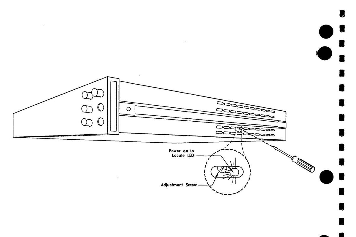

4
Index
Α
AC operational verification, 2-6 flatness, 2-8 frequency accuracy, 2-9 FREO REF output accuracy, 2-9 offset accuracy, 2-7 output resistance, 2-10 voltage amplitude accuracy, 2-6, 2-11 AC performance tests 3-10 amplitude accuracy, 3-10, 3-18 flatness, 3-13, 3-19 FREO REF output accuracy. 3-16 frequency accuracy 3-15 harmonic/spurious levels, 3-14, 3-18 offset accuracy, 3-13 output resistance, 3-17 square wave rise time. 3-15. 3-20 square wave symmetry, 3-15 test records. 3-1 Adjustments, 4-1 automated procedure, 4-7 commands, 4-1 defined, 1-1, 4-1 equipment required. 4-1 hardware lock-out, 4-4 manual procedure, 4-5, 4-7 securing, 4-2 software. 4-1. 4-7 Adjustments, securing disabling security, 4-3 hardware lock-out. 4-4 security code, 4-2 changing, 4-3 disabling, 4-3 factory setting, 4-2 setting, 4-2
С
Calibration cycle, 3-1 guidelines, 1-1 procedures, 4-1 Current limitations, 1-2 Current tests operational verification, 2-4 performance, 3-6
D
DC operational verification, 2-2 current amplitude accuracy, 2-4 test records, 2-1 voltage amplitude accuracy, 2-2, 2-10 voltage zero ohm resistance, 2-4 DCI performance tests, 3-6 amplitude accuracy, 3-6 output resistance, 3-8 test records, 3-1 voltage compliance, 3-9 DCV performance tests, 3-2 amplitude accuracy, 3-2, 3-17 high-resolution settling time, 3-4 test records, 3-1 zero ohm output resistance, 3-5
Ε
Equipment required adjustments, 4-1 operational verification, 2-1 performance tests, 3-1
Η
Hardware lock-out, 4-4 High-resolution settling time, 3-4
L
Lock-out, hardware, 4-4
М
Manual adjustment, 4-5
0
Operational verification defined 1-1. 2-1 equipment required, 2-1 procedures, 2-1 test records. 2-1 Operational verification tests, DC current amplitude accuracy. 2-4 test records. 2-1 voltage amplitude accuracy, 2-2, 2-10 voltage zero ohm resistance. 2-4 Operational verification tests, AC amplitude accuracy 2-6 2-11 flatness, 2-8 frequency accuracy, 2-9 FREO REF output accuracy, 2-9 offset accuracy, 2-7 test records, 2-1 Output resistance test, 2-4, 2-10, 3-5, 3-8
Ρ
Performance tests defined, 1-1, 3-1 equipment required, 3-1 procedure, 3-1 test records, 3-1 Performance tests, ACV amplitude accuracy, 3-10, 3-18 flatness, 3-13, 3-19 frequency accuracy, 3-15 harmonic/spurious levels, 3-14, 3-18 offset accuracy, 3-13 FREQ REF output accuracy, 3-16 square wave rise time, 3-15, 3-20 square wave symmetry, 3-15 test records, 3-1
Performance tests, DCI amplitude accuracy, 3-6 output resistance, 3-8 test record, 3-1 voltage compliance, 3-9 Performance tests, DCV amplitude accuracy, 3-2, 3-17 high-resolution settling, 3-4 test records, 3-1 zero ohm resistance, 3-5
S
Safety information, v Safety symbols, vi Security code changing, 4-3 disabling, 4-3 factory setting, 4-2 setting, 4-2 Settling time, high-resolution, 3-4 Software, adjustment procedure, 4-1
Т
Tests operational verification, 2-1 performance tests, 3-1 Test records operational verification, 2-1 performance tests, 3-1
۷
Verification operational, 2-1 performance, 3-1 Voltage limitations, 1-2
W
Warnings and cautions, 1-2 Warranty information, v

Copyright © 1993 Hewlett-Packard Company Printed in U.S.A. E0591


 Loading...