

Universal Source HP 3245A
Repair Manual
The information in this manual applies directly to HP 3245A Universal Sources (Standard, Option 001, and Option 002) with serial number prefixes 2831A.

Copyright © Hewlett-Packard Company, 1992
Manual Part Number: 03245-90015 Microfiche Part Number: 03245-99015
Printed: October 1992 Edition 1 Printed in U.S.A. E1092
Notice
Hewlett-Packard to Agilent Technologies Transition
This manual may contain references to HP or Hewlett-Packard. Please note that Hewlett-Packard's former test and measurement, semiconductor products and chemical analysis businesses are now part of Agilent Technologies. To reduce potential confusion, the only change to product numbers and names has been in the company name prefix: where a product name/number was HP XXXX the current name/number is now Agilent XXXX. For example, model number HP8648 is now model number Agilent 8648.
Contacting Agilent Sales and Service Offices
The sales and service contact information in this manual may be out of date. The latest service and contact information for your location can be found on the Web at:
http://www.agilent.com/find/assist
If you do not have access to the Internet, contact your field engineer or the nearest sales and service office listed below. In any correspondence or telephone conversation, refer to your instrument by its model number and full serial number.
United States (tel) 1 800 452 4844 (fax) 1 800 829 4433
Canada (tel) +1 877 894 4414 (fax) +1 888 900 8921
Europe (tel) (31 20) 547 2323 (fax) (31 20) 547 2390
Latin America (tel) (305) 269 7500 (fax) (305) 269 7599
Japan (tel) (81) 426 56 7832 (fax) (81) 426 56 7840
Australia (tel) 1 800 629 485 (fax) (61 3) 9210 5947
New Zealand (tel) 0 800 738 378 (fax) 64 4 495 8950
Asia Pacific (tel) (852) 3197 7777 (fax) (852) 2506 9284

CERTIFICATION
Hewlett-Packard Company certifies that this product met its published specifications at the time of shipment from the factory. Hewlett-Packard further certifies that its calibration measurements are traceable to the United States National Institute of Standards and Technology (formerly National Bureau of Standards), to the extent allowed by that organization's calibration facility, and to the calibration facilities of other International Standards Organization members.
WARRANTY
This Hewlett-Packard product is warranted against defects in materials and workmanship for a period of three years from date of shipment. Duration and conditions of warranty for this product may be superseded when the product is integrated into (becomes a part of) other HP products. During the warranty period, Hewlett-Packard Company will, at its option, either repair or replace products which prove to be defective.
For warranty service or repair, this product must be returned to a service facility designated by Hewlett-Packard (HP). Buyer shall prepay shipping charges to HP and HP shall pay shipping charges to return the product to Buyer. However, Buyer shall pay all shipping charges, duties, and taxes for products returned to HP from another country.
HP warrants that its software and firmware designated by HP for use with a product will execute its programming instructions when properly installed on that product. HP does not warrant that the operation of the product, or software, or firmware will be uninterrupted or error free.
LIMITATION OF WARRANTY
The foregoing warranty shall not apply to defects resulting from improper or inadequate maintenance by Buyer, Buyer-supplied products or interfacing, unauthorized modification or misuse, operation outside of the environmental specifications for the product, or improper site preparation or maintenance.
The design and implementation of any circuit on this product is the sole responsibility of the Buyer. HP does not warrant the Buyer's circuitry or malfunctions of HP products that result from the Buyer's circuitry. In addition, HP does not warrant any damage that occurs as a result of the Buyer's circuit or any defects that result from Buyer-supplied products.
NO OTHER WARRANTY IS EXPRESSED OR IMPLIED. HP SPECIFICALLY DISCLAIMS THE IMPLIED WARRANTIES OF MER-CHANTABILITY AND FITNESS FOR A PARTICULAR PURPOSE.
EXCLUSIVE REMEDIES
THE REMEDIES PROVIDED HEREIN ARE BUYER'S SOLE AND EXCLUSIVE REMEDIES. HP SHALL NOT BE LIABLE FOR ANY DI-RECT, INDIRECT, SPECIAL, INCIDENTAL, OR CONSEQUENTIAL DAMAGES, WHETHER BASED ON CONTRACT, TORT, OR ANY OTHER LEGAL THEORY.
NOTICE
The information contained in this document is subject to change without notice. HEWLETT-PACKARD (HP) MAKES NO WARRANTY OF ANY KIND WITH REGARD TO THIS MATERIAL, INCLUDING, BUT NOT LIMITED TO, THE IMPLIED WARRANTIES OF MER-CHANTABILITY AND FITNESS FOR A PARTICULAR PURPOSE. HP shall not be liable for errors contained herein or for incidental or consequential damages in connection with the furnishing, performance or use of this material. This document contains proprietary information which is protected by copyright. All rights are reserved. No part of this document may be photocopied, reproduced, or translated to another language without the prior written consent of Hewlett-Packard Company. HP assumes no responsibility for the use or reliability of its software on equipment that is not furnished by HP.
Restricted Rights Legend
Use, duplication, or disclosure by the Government is subject to restrictions as set forth in subdivision (b)(3)(ii) of the Rights in Technical Data and Computer Software clause at 52.227-7013. Hewlett-Packard Company; 3000 Hanover Street; Palo Alto, California 94304
Declaration of Conformity According to ISO/IEC Guide 22 and EN 45014
Accoraing to ISO/IEC Guiae 22 and EN 45014
The Hewlett-Packard Company declares that the HP 3245A conforms to the following Product Specifications.
Safety: IEC 1010-1 (1990) CSA 234
CSA 234 UL 1244 EMC: CISPR 1
CISPR 11:1990/EN 55011 (1991): Group1 Class A IEC 801-2:1991/EN 50082-1 (1992): 4kVCD, 8kVAD IEC 801-3:1984/EN 50082-1 (1992): 3 V/m IEC 801-4:1988/EN 50082-1 (1992): 1kV
Q.A. Manager October 1992
Hewlett-Packard Company P.O. Box 301 815 14th Street S.W. Loveland, Colorado 80539 U.S.A
Printing History
The Printing History shown below lists all Editions and Updates of this manual and the printing date(s). The first printing of the manual is Edition 1. The Edition number increments by 1 whenever the manual is revised. Updates, which are issued between Editions, contain replacement pages to correct the current Edition of the manual. Updates are numbered sequentially starting with Update 1. When a new Edition is created, it contains all the Update information for the previous Edition. Each new Edition or Update also includes a revised copy of this printing history page. Many product updates or revisions do not require manual changes and, conversely, manual corrections may be done without accompanying product changes. Therefore, do not expect a one-to-one correspondence between product updates and manual updates.
Edition 1 (Part Number 03245-90015)..... October 1992
Instruction manual symbol affixed to product. Indicates that the user must refer to the manual for specific Warning or Caution information to avoid personal injury or damage to the product.
Indicates the field wiring terminal that must be connected to earth ground before operating the equipment—protects against electrical shock in case of fault.
→ OR → Frame or chassis ground terminal—typically connects to the equipment's metal frame.
| Alternating current (AC). | |
|---|---|
| Direct current (DC). | |
| 4 | Indicates hazardous voltages. |
| WARNING | Calls attention to a procedure, practice, or condition that could cause bodily injury or death. |
| CAUTION |
Calls attention to a procedure, practice, or
condition that could possibly cause damage to equipment or permanent loss of data. |
WARNINGS
Safety Symbols
The following general safety precautions must be observed during all phases of operation, service, and repair of this product. Failure to comply with these precautions or with specific warnings elsewhere in this manual violates safety standards of design, manufacture, and intended use of the product. Hewlett-Packard Company assumes no liability for the customer's failure to comply with these requirements.
Ground the equipment: For Safety Class 1 equipment (equipment having a protective earth terminal), an uninterruptible safety earth ground must be provided from the mains power source to the product input wiring terminals or supplied power cable.
DO NOT operate the product in an explosive atmosphere or in the presence of flammable gases or fumes.
For continued protection against fire, replace the line fuse(s) only with fuse(s) of the same voltage and current rating and type. DO NOT use repaired fuses or short-circuited fuse holders.
Keep away from live circuits: Operating personnel must not remove equipment covers or shields. Procedures involving the removal of covers or shields are for use by service-trained personnel only. Under certain conditions, dangerous voltages may exist even with the equipment switched off. To avoid dangerous electrical shock, DO NOT perform procedures involving cover or shield removal unless you are qualified to do so.
DO NOT operate damaged equipment: Whenever it is possible that the safety protection features built into this product have been impaired, either through physical damage, excessive moisture, or any other reason, REMOVE POWER and do not use the product until safe operation can be verified by service-trained personnel. If necessary, return the product to a Hewlett-Packard Sales and Service Office for service and repair to ensure that safety features are maintained.
DO NOT service or adjust alone: Do not attempt internal service or adjustment unless another person, capable of rendering first aid and resuscitation, is present.
DO NOT substitute parts or modify equipment: Because of the danger of introducing additional hazards, do not install substitute parts or perform any unauthorized modification to the product. Return the product to a Hewlett-Packard Sales and Service Office for service and repair to ensure that safety features are maintained.
Manual Overview
This manual shows how to service and repair the HP 3245A Universal Source. See the HP 3245A Universal Source Operating and Programming Manual (part number 03245-90003) for additional information on operating and programming the HP 3245A. See the HP 3245A Universal Source Calibration Manual (03245-90013) for Operation Verification and Performance Tests for the HP 3245A. See the HP 3245A Universal Source Component Level Information Packet (CLIP) (03245-90033) for detailed parts lists, component locators, and schematics for the HP 3245A.
Manual Content
| Chap | Title | Content |
|---|---|---|
| 1 |
General
Information |
Lists basic HP 3245A description, tools and test equipment required for service, and procedures to inspect and ship the HP 3245A. |
| 2 |
Replaceable
Parts |
Lists part numbers for user-replaceable parts in the HP 3245A. Provides information on ordering spare parts and shows component part locators. |
| 3 | Service | Procedures to aid in fault isolation and repair of the HP 3245A. |
Contents
| Chapter 1 - General Information | |
|---|---|
| Introduction | .1-1 |
| Safety Considerations | .1-1 |
| Description | .1-3 |
| Specifications | .1-3 |
| Environment | .1-4 |
| Serial Numbers | .1-4 |
| Configurations and Options | .1-4 |
| Recommended Test Equipment | .1-5 |
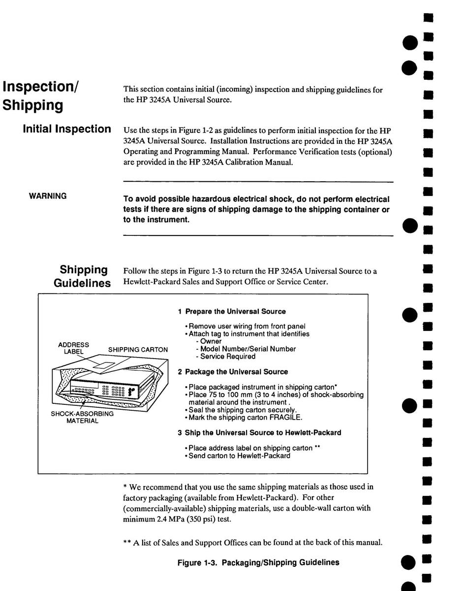
| Inspection/Shipping | .1-6 |
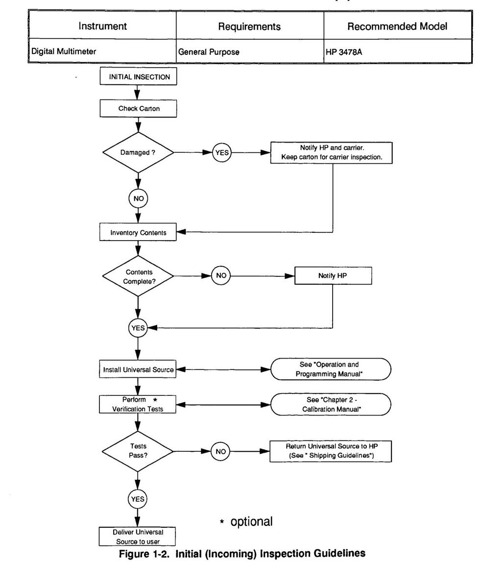
| Initial Inspection | .1-6 |
| Shipping Guidelines | .1-6 |
| Chapter 2 - Replaceable Parts | |
| Introduction | 2-1 |
| Replaceable Parts List | .2-1 |
| Parts Locators | 2-7 |
| , | |
| Chapter 3 - Service | |
| Introduction | .3-1 |
| Equipment Required | .3-1 |
| Service Aids | .3-1 |
| Troubleshooting Techniques | .3-1 |
| Identifying the Problem | .3-2 |
| Making Visual Checks | .3-2 |
| Turn-on Failures | .3-3 |
| Self-test Failures | .3-6 |
| TEST | .3-6 |
| FTEST | .3-7 |
| Performance Failures | .3-8 |
| Miscellaneous Failures | .3-8 |
| Assembly/Disassembly Procedures | .3-9 |
| Covers | .3-10 |
| A1/A11 Inguard Source PCA | .3-11 |
| A2 Backplane PCA | .3-13 |
| A3 High Voltage Amplifier PCA (Option 002 only) | .3-14 |
| A5 Outguard Logic PCA | .3-15 |
| A6 Outguard Power Supply PCA | .3-16 |
| A7 Display Logic PCA | .3-17 |
| Repair and Maintenance Guidelines | .3-18 |
| ESD Precautions | .3-18 |
| Soldering Printed Circuit Boards | .3-18 |
1 General Information
Introduction
This service manual contains information required to troubleshoot and repair the HP 3245A Universal Source to the assembly level (e.g. circuit card, module, etc).
See the HP 3245A Calibration Manual for information on performance verification, and the HP 3245A Operating and Programming Manual for additional information on operation.
Figure 1-1 shows a standard single channel HP 3245A Universal Source. Option 001 adds channel B output capability, and Option 002 adds high voltage output capability.
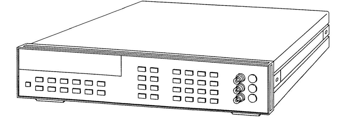
Figure 1-1. HP 3245A Universal Source and Accessories
NOTE
The A1 and A2 assemblies have been changed to accommodate the high voltage option for the HP 3245A Universal Source. Units with serial numbers 2831A01139 and after have REV C A1 and A2 assemblies installed.
Safety Considerations
This product is a Safety Class I instrument that is provided with a protective earth terminal when properly connected to the main power source. Check all related documentation for safety markings and instructions before operation or service.
Refer to the WARNINGS page in this manual for a summary of safety information. Safety information for testing and service follows and is also found throughout this manual.
Warnings This section contains WARNINGS which must be followed for your protection when performing equipment maintenance or repair.
WARNING
SERVICE-TRAINED PERSONNEL ONLY. The information in this manual is for service-trained personnel who are familiar with electronic circuitry and are aware of the hazards involved. To avoid personal injury or damage to the instrument, do not perform procedures in this manual or do any servicing unless your are gualified to do so.
CHECK POWER SETTINGS. Before applying power, verify that the rear panel line switch setting matches the line voltage and that the correct fuse is installed. An uninterruptible safety earth ground must be provided from the main power source to the supplied power cord set.
GROUNDING REQUIREMENTS. Interruption of the protective (grounding) conductor (inside or outside the instrument) or disconnecting the protective earth terminal will cause a potential shock hazard that could result in personal injury. (Grounding one conductor of a two-conductor outlet is not sufficient protection.)
IMPAIRED PROTECTION. Whenever it is likely that instrument protection has been impaired, the instrument must be made inoperative and be secured against any unintended operation.
REMOVE POWER IF POSSIBLE. Some procedures in this manual may be performed with power supplied to the instrument while protective covers are removed. Energy available at many points may, if contacted, result in personal injury. (If maintenance can be performed without power applied, the power should be removed.)
USING AUTOTRANSFORMERS. If the instrument is to be energized via an autotransformer (for voltage reduction) make sure the common terminal is connected to neutral (that is, the grounded side of the main's supply).
CAPACITOR VOLTAGES. Capacitors inside the instrument may remain charged even when the instrument has been disconnected from its source of supply USE PROPER FUSES. For continued protection against fire hazard. replace the line fuses only with fuses of the same current rating and type (such as normal blow, time delay, etc.). Do not use repaired fuses or short-circuited fuseholders Cautions This section contains CAUTIONS which must be followed to avoid damage to the equipment when performing instrument maintenance or repair. CAUTION Static electricity is a major cause of component failure. To prevent damage to the electrical components in the instrument, observe anti-static techniques whenever working on the HP 3245A. Description The HP 3245A Universal Source generates precise DC voltage and current outputs, and AC waveforms. DC voltage outputs from -10.25 Vdc to + 10.25 Vdc with 6 digits of resolution (24 bits) in high resolution mode, or 3.5 digits (12 bits) in low resolution mode, are available. DC current outputs are available from -0.1A to +0.1A. AC outputs include sine, square, and arbitrary waveforms up to 1 MHz. Ramp waveforms with variable duty cycles from 5% to 95% are available up to 100 kHz Option 001 adds a second channel (B) output, sync out, and trigger I/O capability. Option 002 adds a 10x High Voltage Amplifier to provide 200 V peak-to-peak (AC voltage) and 100 V (DC voltage) output capability. The HP 3245A also has seven voltage ranges, four current ranges, selectable output impedance, and selectable trigger and timing functions. See the HP 3245A Operating and Programming Manual for additional information. Specifications See Appendix A of the HP 3245A Operating and Programming Manual for specifications.
Environment
The recommended operating environment for the HP 3245A Universal Source is:
| Environment | Temperature | Humidity |
|---|---|---|
| Operating | 0°C to +55°C | <95% relative 0°C to +40°C |
| Storage and shipment | -40°C to +75°C | <95% relative 0°C to +40°C |
Serial Numbers
Instruments covered by this manual are identified by a serial number prefix listed on the title page. Hewlett-Packard uses a two-part serial number in the form XXXXAYYYYY, where XXXX is the serial prefix, A is the country of origin (A = USA), and YYYYY is the serial suffix. The serial number prefix identifies a series of identical instruments. The serial number suffix is assigned sequentially to each instrument.
The serial number plate is located on the rear panel. If the serial number prefix of your instrument is greater than the one listed on the title page, a Manual Update (as required) will explain how to adapt this manual to your instrument.
Configurations and Options
The standard HP 3245A is a single channel universal source with channel A output only. This unit can be field upgraded to a two channel source (Option 001) by adding a second Inguard Source PCA for channel B output capability. There is also a High Voltage Option (Option 002) available. However, this option can only be added to instruments with Inguard Source PCA (A1) and Backplane PCA (A2) of Rev C or higher installed.
NOTE
All instruments with serial numbers prior to 2831A01139 have the Inguard Source PCA (A1) and Backplane PCA (A2) revision B assemblies installed. Instruments with serial numbers greater than 2831A01139 have revision C assemblies installed.
The High Voltage Option (Option 002) can only be installed in units with revision C assemblies.
See Chapter 2 - Replaceable Parts for assembly part numbers and locations.
Recommended Test Equipment
Table 1-1 lists the test equipment recommended for troubleshooting the HP 3245A Universal Source. Essential requirements for each piece of test equipment are described in the Requirements column.
Table 1-1. Recommended Test Equipment
2 Replaceable Parts
Introduction
.
This chapter contains information to order replaceable parts for the HP 3245A Universal Source. Table 2-1 lists the assembly part numbers and quantities for all currently available HP 3245A Universal Source configurations. Table 2-2 lists the assembly, electrical part, and mechanical part numbers for the Universal Source. Table 2-3 shows reference designators for parts in Table 2-2, and Table 2-4 shows the manufacturer code list for these parts.
To order a part listed in Table 2-2, specify the Hewlett-Packard part number and the quantity required. Send the order to your nearest Hewlett-Packard Sales and Support Office. A list of Sales and Support Offices is at the back of this manual.
Replaceable Parts List
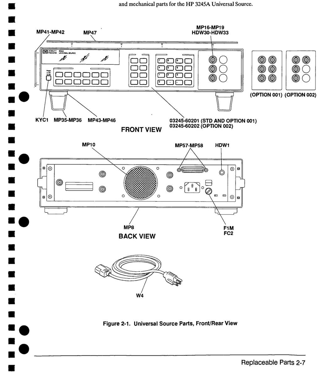
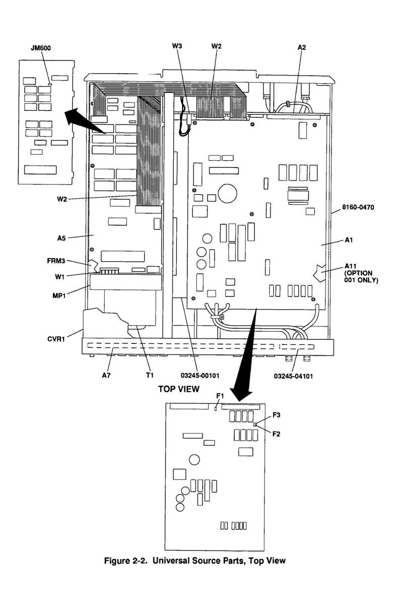
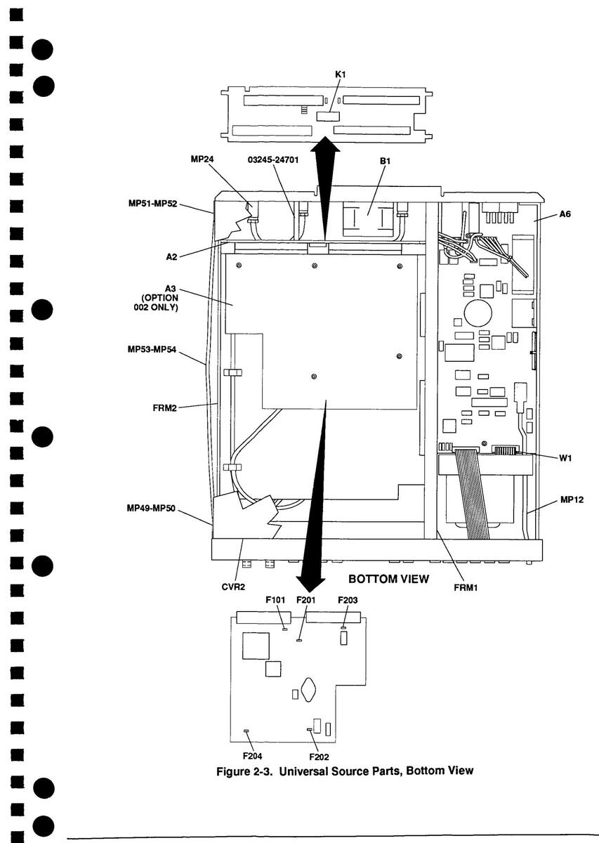
Table 2-2, HP 3245A Universal Source Replaceable Parts, lists replaceable parts for the Universal Source. See Figure 2-1, Figure 2-2, or Figure 2-3 for locations of selected parts.
|
HP 3245A
Option |
Reference Designator a
Number (prior to serial r 2831A01139) |
nd Part
number |
Reference Designator a
Number (serial number 28 to 2831A01562) |
nd Part
331A01140 |
Reference Designator a
Number (serial number 28 and later) |
und Part
331A01563 |
|---|---|---|---|---|---|---|
| Standard | A1 03245-66501 REV B | [1 ea] | A1 03245-66511 REV C | [1 ea] | A1 03245-66511 REV C | [1 ea] |
| A2 03245-66502 REV B | [1 ea] | A2 03245-66502 REV C | [1 ea] | A2 03245-66502 REV C | [1 ea] | |
| A5 03245-66505 | [1 ea] | A5 03245-66505 | [1 ea] | A5 03245-66505 | [1 ea] | |
| A6 03245-66506 | [1 ea] | A6 03245-66506 | [1 ea] | A6 03245-66506 | [1 ea] | |
| A7 03458-66507 | [1 ea] | A7 03458-66507 | [1 ea] | A7 03458-66507 | [1 ea] | |
| Option 001 | A1 03245-66501 REV B | [1 ea] | A1 03245-66511 REV C | [1 ea] | A1 03245-66511 REV C | [1 ea] |
| A2 03245-66502 REV B | [1 ea] | A2 03245-66502 REV C | [1 ea] | A2 03245-66502 REV C | [1 ea] | |
| A5 03245-66505 | [1 ea] | A5 03245-66505 | [1 ea] | A5 03245-66505 | [1 ea] | |
| A6 03245-66506 | [1 ea] | A6 03245-66506 | [1 ea] | A6 03245-66506 | [1 ea] | |
| A7 03458-66507 | [1 ea] | A7 03458-66507 | [1 ea] | A7 03458-66507 | [1 ea] | |
| A11 03245-66501 REV B | [1 ea] | A11 03245-66511 REV C | [1 ea] | A11 03245-66511 REV C | [1 ea] | |
| Option 002 | N/A |
A1 03245-66511 REV C
A2 03245-66502 REV C A3 03245-66503 A5 03245-66505 A6 03245-66506 A7 03458-66507 |
[1 ea]
[1 ea] [1 ea] [1 ea] [1 ea] [1 ea] |
A1 03245-66517
A2 03245-66516 A3 03245-66503 A5 03245-66505 A6 03245-66506 A7 03458-66507 |
[1 ea]
[1 ea] [1 ea] [1 ea] [1 ea] [1 ea] |
Table 2-1. HP 3245A Configurations/Options
Table 2-2. HP 3245A Universal Source Replaceable Parts
| Table 2-2. HP 3245A Universal Source Re | placeab | le Parts | |||
|---|---|---|---|---|---|
|
Reference
Designator |
HP Part Number | Qty | Part Description |
Mfr.
Code |
Mfr. Part Number |
|
A1
A1 A2 A2 A3 A5 A6 A7 A11 |
03245-66511
03245-66517 03245-66502 03245-66503 03245-66503 03245-66505 03245-66506 03458-66507 03245-66511 03245-60201 |
1
1 1 1 1 |
ASSEMBLIES/CABLES/MANUALS
ASSEMBLIES (SEE FIGURE 2-1 FOR LOCATION - REFER TO TABLE 2-1 FOR USAGE INFORMATION) INGUARD SOURCE PCA (STD AND OPTION 001) INGUARD SOURCE PCA (OPTION 002) BACKPLANE PCA (STD AND OPTION 001) BACKPLANE PCA (OPTION 002) HIGH VOLTAGE AMP PCA (OPTION 002) OUTGUARD LOGIC PRINTED CIRCUIT ASSEMBLY OUTGUARD PWR SUPPLY PRINTED CIRCUIT ASSY DISPLAY LOGIC PRINTED CIRCUIT ASSEMBLY INGUARD SOURCE PCA (OPTION 001) FRONT PANEL ASSEMBLY (STD AND OPTION 001) |
28480
28480 28480 28480 28480 28480 28480 28480 28480 28480 28480 |
03245-66511
03245-66517 03245-66502 03245-66503 03245-66503 03245-66505 03245-66506 03458-66507 03245-66511 03245-60201 |
|
W1
W2 W3 W4 |
03245-60202
03458-61601 03245-61604 03458-61602 8120-1378 |
1
1 1 |
FRONT PANEL ASSEMBLY (OPTION 002)
CABLES (SEE FIGURE 2-1) 20-PIN RIBBON CABLE ASSEMBLY 3M RIBBON 40P/20P CABLE ASSEMBLY EXT I/O 4-WIRE CABLE ASSEMBLY CABLE ASSEMBLY 18AWG |
28480
28480 28480 28480 16428 |
03245-60202
03458-61601 03458-61602 03245-61604 CH7081 |
|
03245-90001
03245-90013 |
MANUALS
OPERATING AND PROGRAMMING CALIBRATION |
28480
28480 |
03245-90001
03245-90013 |
||
|
B1
F1M FC2 J1 J2 T1 |
03458-68501
2110-0202 2110-0565 1250-0083 1250-0083 9100-4749 |
1
1 1 1 1 |
ELECTRICAL PARTS (SEE FIGURE 2-1)
FAN ASSEMBLY FUSE .5A 250V 1.25X.25 UL FUSEHOLDER CAP 12A MAX FOR UL CONNECTOR-RF BNC FEM SGL-HOLE FR 50-OHM CONNECTOR-RF BNC FEM SGL-HOLE FR 50-OHM TRANSFORMER-POWER 100/120/220/240V |
28480
16428 28480 24931 24931 05216 |
03458-68501
MDL-1/2 2110-0565 28JR130-1 28JR130-1 PX4881 |
|
MECHANICAL PARTS (SEE FIGURE 2-1) - COMMON
HARDWARE NOT ILLUSTRATED |
|||||
|
CVR1
CVR2 FRM1 FRM2 FRM3 |
03458-04101
03458-04102 03458-00104 03458-00106 03458-00105 |
1
1 1 1 |
COVER, TOP
COVER, BOTTOM GUSSET, CENTER CHASSIS, MAINFRAME CHASSIS, OUTGUARD |
28480
28480 28480 28480 28480 28480 |
03458-04101
03458-04102 03458-00104 03458-00106 03458-00105 |
|
HDW1
HDW2 HDW3 HDW4 HDW5 |
1510-0038
2950-0006 2190-0027 2190-0119 2190-0577 |
1
1 2 2 |
BINDING POST ASSY SGL THD-STUD
NUT-HEX-DBL-CHAM 1/4-32-THD .094-IN-THK WASHER-LK INTL T 1/4 IN .256-IN-ID WASHER-FL 15/32 IN .48-IN-ID .75-IN-OD WASHER-LK NO. 10 .194-IN-ID .294-IN-OD |
74970
73734 78189 73734 28480 |
111-2223-001
9000 1914-00 1499 2190-0577 |
|
HDW6
HDW7 HDW8 HDW9 HDW10 |
2190-0577
2190-0432 2190-0432 2190-0432 2190-0432 2190-0432 |
4 |
WASHER-LK NO. 10 .194-IN-ID .294-IN-OD
WASHER-LK 5/16 IN .319-IN-ID .575-IN-OD WASHER-LK 5/16 IN .319-IN-ID .575-IN-OD WASHER-LK 5/16 IN .319-IN-ID .575-IN-OD WASHER-LK 5/16 IN .319-IN-ID .575-IN-OD |
28480
28480 28480 23460 28480 |
2190-0577
2190-0432 2190-0432 2190-0432 2190-0432 2190-0432 |
Table 2-2 HB 3245A Universal Source Replaceable Parts
|
Reference
Designator |
HP Part Number | Qty | Part Description |
Mfr.
Code |
Mfr. Part Nu | |
|---|---|---|---|---|---|---|
|
MECHANICAL PARTS (SEE FIGURE 2-1) - COMMON
HARDWARE NOT ILLUSTRATED |
||||||
| 0100 0110 | 70704 | 1400 | ||||
| 2190-0119 | 4 | WASHER-FL 15/32 IN 48-IN-ID .75-IN-OD | 70100 | 1499 | ||
| 2190-0037 |
ן
ב |
54204 | 1224-00 | |||
| 2190-0099 | 5 | 54294 | 10-000 | |||
| HDW14 | 2190-0099 |
WASHER-LK 7/16 IN .472-IN-ID .607-IN-OD
WASHER-LK 7/16 IN .472-IN-ID .607-IN-OD |
54294 | 16-886 | ||
| HDW16 | 2190-0099 | _ | WASHER-LK 7/16 IN .472-IN-ID .607-IN-OD | 54294 | 16-886 | |
| HDW17 | 2950-0035 | 5 | NUT-HEX-DBL-CHAM 15/32-32-THD | 28480 | 2950-0035 | |
| HDW18 | 2950-0035 | NUT-HEX-DBL-CHAM 15/32-32-THD | 28480 | 2950-0035 | ||
| HDW19 | 2950-0035 | NUT-HEX-DBL-CHAM 15/32-32-THD | 28480 | 2950-0035 | ||
| HDW20 | 2950-0054 | 1 | NUT-HEX-DBL-CHAM 1/2-28-THD .125-IN-THK | 28480 | 2950-0054 | |
| HDW21 | 2950-0001 | 2 |
|
| NUT-HEX-DBL-CHAM 3/8-32-THD .094-IN-THK |
73734 | 9002 | |
| 2950-0001 | - | NUT-HEX-DBL-CHAM 3/8-32-THD 094-IN-THK | 73734 | 9002 | ||
| 0360-1632 | 2 | TERMINAL-SOLDER LUG LK-MTG FOR-#3/8-SCB | 79963 | 761-3/8 | ||
| 0260 1622 | 4 | 70062 | 761-3/8 | |||
| HDW25 | 2190-0099 | WASHER-LK 7/16 IN .472-IN-ID .607-IN-OD | 54294 | 16-886 | ||
| HDW26 | 2950-0035 | NUT-HEX-DBL-CHAM 15/32-32-THD | 28480 | 2950-0035 | ||
| HDW27 | 2950-0035 | NUT-HEX-DBL-CHAM 15/32-32-THD | 28480 | 2950-0035 | ||
| HDW28 | 3050-0604 | 2 | WASHER-FL 7/16 IN .5-IN-ID .75-IN-OD | 86928 | 5710-94-16 | |
| HDW29 | 3050-0604 | WASHER-FL 7/16 IN .5-IN-ID .75-IN-OD | 86928 | 5710-94-16 | ||
| HDW30 | 00310-48801 | 4 | INSULATOR | 28480 | 00310-48801 | |
| HDW31 | 00310-48801 | INSULATOR | 28480 | 00310-48801 | ||
| HDW32 | 00310-48801 | INSULATOR | 28480 | 00310-48801 | ||
| HDW33 | 00310-48801 | INSULATOR | 28480 | 00310-48801 | ||
| HDW34 | 3050-0891 | 1 | WASHER-FL 3.0 MM 3.3-MM-ID 6.85-MM-OD | 28480 | 3050-0891 | |
| KYC1 | 5041-0564 | 1 | PB 1/4-COWHT | 28480 | 5041-0564 | |
| 02459 01201 | 1 | 28480 | 03458-01201 | |||
| 03450-01201 |
1
A |
28400 | 03459-24701 | |||
| 03458-24/01 | 4 | 20400 | 02459 24701 | |||
| 03458-24/01 | 20400 | 03450 04704 | ||||
| MP6 | 03458-24701 | STANDUFF-HEX, (MALE/FEMALE) | 28480 | 03458-24/01 | ||
| MP7 | 03458-24701 | STANDUFF-HEX, (MALE/FEMALE) | 28480 | 03458-24701 | ||
| MP8 | 03458-47901 | 1 | BEZEL OVERLAY, REAR | 28480 | 03458-47901 | |
| MP9 | 03458-84303 | 1 | LABEL, KEYBOARD OVERLAY | 28480 | 03458-84303 | |
| MP10 | 3150-0300 | 1 | FILTER-AIR NYLON 2.3-IN-OD .75-IN-LG | 28480 | 3150-0300 | |
| MP11 | 2190-0586 | 4 | WASHER-LK HLCL 4.0 MM 4.1-MM-ID 7.6-MM-OD | 28480 | 2190-0586 | |
| MP12 | 03458-43701 | 1 | PUSHROD, 186.2 L | 28480 | 03458-43701 | |
| MP13 | 2190-0586 | WASHER-I K HI CL 4.0 MM 4 1-MM-ID 7.6-MM-OD | 28480 | 2190-0586 | ||
| MD14 | 2100-0506 | WASHER I K HI CL 4 0 MM 4 1-MM ID 7 6-MM-OD | 28480 | 2190-0586 | ||
| 2190-0500 | 28490 | 2100-0586 | ||||
| MP15 | 2190-0586 | • | 20400 | 102204 | ||
| MP16 | 0390-0006 | 4 | 70704 | 103304 | ||
| MP17 | 0390-0006 | INSULATOR-FLANGE-BUSHING NYLON | /3/34 | 103304 | ||
| Table 2-2. | HP 3245A Universal Source | Replaceable Parts |
|
Reference
Designator |
HP Part Number | Qty | Part Description |
Mfr.
Code |
Mfr. Part Number |
|---|---|---|---|---|---|
|
MECHANICAL PARTS (SEE FIGURE 2-1) - COMMON
HARDWARE NOT ILLUSTRATED |
|||||
| MP18 | 0390-0006 | INSULATOR-FLANGE-BUSHING NYLON | 73734 | 103304 | |
| MP19 | 0390-0006 | INSULATOR-FLANGE-BUSHING NYLON | 73734 | 103304 | |
| MP20 | 3050-0893 | 4 | WASHER-FL 4.0 MM 4.4-MM-ID 8.85-MM-OD | 28480 | 3050-0893 |
| MP21 | 3050-0893 | WASHER-FL 4.0 MM 4.4-MM-ID 8.85-MM-OD | 28480 | 3050-0893 | |
| MP22 | 3050-0893 | WASHER-FL 4.0 MM 4.4-MM-ID 8.85-MM-OD | 28480 | 3050-0893 | |
| MP23 | 3050-0893 | WASHER-FL 4.0 MM 4.4-MM-ID 8.85-MM-OD | 28480 | 3050-0893 | |
| MP24 | 1250-0161 | 1 | ADAPTER-COAX STRAIGHT F-BNC F-BNC | 24931 | 28AS101-2 |
| MP25 | 1400-0249 | 4 | CABLE TIE .062625-DIA .091-WD NYLON | 59730 | TY-23M-8 |
| MP26 | 1400-0249 | CABLE TIE .062625-DIA .091-WD NYLON | 59730 | TY-23M-8 | |
| MP27 | 1400-0249 | CABLE TIE .062625-DIA .091-WD NYLON | 59730 | TY-23M-8 | |
| MP28 | 1400-0249 | CABLE TIE .062625-DIA .091-WD NYLON | 59730 | TY-23M-8 | |
| MP34 | 1460-1311 | 1 | SPRING, GROUND | 28480 | 1460-1311 |
| MP35 | 1460-1345 | 2 | TILT STAND STAINLESS STEEL | 28480 | 1460-1345 |
| MP36 | 1460-1345 | TILT STAND STAINLESS STEEL | 28480 | 1460-1345 | |
| MP41 | 5001-0538 | 2 | TRIM STRIP SIDE 3 1/2 | 28480 | 5001-0538 |
| MP42 | 5001-0538 | TRIM STRIP SIDE 3 1/2 | 28480 | 5001-0538 | |
| MP43 | 5041-8801 | 4 | FOOT FULL MOD | 28480 | 5041-8801 |
| MP44 | 5041-8801 | FOOT FULL MOD | 28480 | 5041-8801 | |
| MP45 | 5041-8801 | FOOT FULL MOD | 28480 | 5041-8801 | |
| MP46 | 5041-8801 | FOOT FULL MOD | 28480 | 5041-8801 | |
| MP47 | 5041-8802 | 1 | 28480 | 5041-8802 | |
| MP49 | 5041-8819 | 2 | HANDLE CAP | 28480 | 5041-8819 |
| MP50 | 5041-8819 | HANDLE CAP | 28480 | 5041-8819 | |
| MP51 | 5041-8820 | 2 | HANDLE CAP | 28480 | 5041-8820 |
| MP52 | 5041-8820 | HANDLE CAP | 28480 | 5041-8820 | |
| MP53 | 5062-3704 | 2 | STRAP HANDLE-18 INCH | 28480 | 5062-3704 |
| MP54 | 5062-3704 | STRAP HANDLE-18 INCH | 28480 | 5062-3704 | |
| MP57 | 5180-6650 | 2 | STANDOFF, HEX | 28480 | 5180-6650 |
| MP58 | 5180-6650 | STANDOFF, HEX | 28480 | 5180-6650 | |
| SCW1 | 0515-1404 | 4 | SCREW-MACHINE M4 X 0.7 55MM-LG PAN-HD | 28480 | 0515-1414 |
| SCW2 | 0515-1404 | SCREW-MACHINE M4 X 0.7 55MM-LG PAN-HD | 28480 | 0515-1414 | |
| SCW3 | 0515-1404 | SCREW-MACHINE M4 X 0.7 55MM-LG PAN-HD | 28480 | 0515-1414 | |
| SCW4 | 0515-1404 | SCREW-MACHINE M4 X 0.7 55MM-LG PAN-HD | 28480 | 0515-1414 | |
| SCW5 | 0515-0433 | 4 | SCREW-MACHINE ASSY M4 X 0.7 8MM-LG PAN-HD | 28480 | 0515-0433 |
| SCW6 | 0515-0433 | SCREW-MACHINE ASSY M4 X 0.7 8MM-LG PAN-HD | 28480 | 0515-0433 | |
| SCW7 | 0515-0433 | SCREW-MACHINE ASSY M4 X 0.7 8MM-LG PAN-HD | 28480 | 0515-0433 | |
| SCW8 | 0515-0433 | SCREW-MACHINE ASSY M4 X 0.7 8MM-I G PAN-HD | 28480 | 0515-0433 | |
| SCW11 | 0515-0372 | 27 | SCREW-MACHINE ASSY M3 X 0.5 8MM-I G PAN-HD | 28480 | 0515-0372 |
| SCW12 | 0515-0372 | SCREW-MACHINE ASSY M3 X 0.5 8MM-LG PAN-HD | 28480 | 0515-0372 | |
| SCW13 | 0515-0372 | SCREW-MACHINE ASSY M3 X 0.5 8MM-LG PAN-HD | 28480 | 0515-0372 | |
۲ Ì
| Tahla 2-2 | HD 32454 | Universal Source | Renlaceable | Parts |
|---|---|---|---|---|
| I a Die 2-2. | NF 3243A | Universal Source | neplaceable | r ai iə |
|
Reference
Designator |
HP Part Number | Qty | Part Description |
Mfr.
Code |
Mfr. Part Numt |
|---|---|---|---|---|---|
|
MECHANICAL PARTS (SEE FIGURE 2-1) - COMMON
HARDWARE NOT ILLUSTRATED |
|||||
|
SCW14
SCW15 SCW16 SCW17 SCW21 |
0515-0372
0515-0372 0515-0372 0515-0367 0515-0367 0515-1132 |
1 |
SCREW-MACHINE ASSY M3 X 0.5 8MM-LG PAN-HD
SCREW-MACHINE ASSY M3 X 0.5 8MM-LG PAN-HD SCREW-MACHINE ASSY M3 X 0.5 8MM-LG PAN-HD SCREW-MACHINE ASSY M2.5 X 0.45 8MM-LG PAN-HE SCREW-MACHINE M3 X 0.8 10MM-LG FLAT-HD |
28480
28480 28480 28480 28480 28480 |
0515-0372
0515-0372 0515-0372 0515-0367 0515-0367 0515-1132 |
|
SCW22
SCW23 SCW24 SCW41 SCW42 |
0515-1132
0515-1132 0515-1132 0624-0530 0624-0530 |
2 |
SCREW-MACHINE M3 X 0.8 10MM-LG FLAT-HD
SCREW-MACHINE M3 X 0.8 10MM-LG FLAT-HD SCREW-MACHINE M3 X 0.8 10MM-LG FLAT-HD SCREW-TPG 8-16 .375-IN-LG PAN-HD TORX SCREW-TPG 8-16 .375-IN-LG PAN-HD TORX |
28480
28480 28480 28480 28480 28480 |
0515-1132
0515-1132 0515-1132 0624-0530 0624-0530 |
|
03245-00101
03245-04101 03245-04701 03245-24701 03245-69301 03245-81901 03245-84302 0624-0681 1250-0781 1400-0617 5180-0409 8160-0470 |
1
3 1 1 1 1 3 1 2 |
DECK-SOURCE BRD
PLATE-BNC TERMINAL SPACER-BNC MOUNTING (QTY 6 FOR OPTION 001) SPACER-HEX F/F M3.0X50MM WINDOW-DISPLAY SS P/O FRONT PANEL ASSY SW-PADS, RUBBER P/O FRONT PANEL ASSY LABEL-PANEL, REAR SCREW-TPG 4-20 .25-IN-LG PAN-HD-TORX ADAPTER-COAX TEE F-BNC M-BNC F-BNC CLIP-SPRING .375-DIA .375-WD PLASTIC SPRING CLIP RFI STRIP-FINGERS BE-CU SN-PL .38-IN-WD |
28480
28480 28480 28480 28480 28480 28480 28480 28480 24931 06915 28480 30817 |
03245-00101
03245-04101 03245-04701 03245-24701 03245-69301 03245-81901 03245-84302 0624-0681 28AT101-2 TC-30-1 5180-0409 97-541-02-X |
|
|
A1
A1 A11 |
03245-66511
03245-66517 03245-66511 |
INGUARD SOURCE PCA (STD AND OPTION 001)
INGUARD SOURCE PCA (OPTION 002) INGUARD SOURCE PCA (OPTION 001) |
28480
28480 28480 |
03245-66511
03245-66517 03245-66511 |
|
|
A1/A11F1
A1/A11F2 A1/A11F3 |
2110-0698
2110-0698 2110-0698 |
3 |
FUSE-SUBMINIATURE 2.5A 125V NTD AX
FUSE-SUBMINIATURE 2.5A 125V NTD AX FUSE-SUBMINIATURE 2.5A 125V NTD AX |
75915
75915 75915 |
R25102.5T1
R25102.5T1 R25102.5T1 |
|
A2
A2 |
03245-66502
03245-66516 |
BACKPLANE PCA (STD AND OPTION 001)
BACKPLANE PCA (OPTION 002) |
28480
28480 |
03245-66502
03245-66516 |
|
| A2K1 | 0490-1423 | 1 | RELAY-REED 1C 250MA 28VDC 5VDC COIL 3VA | 71707 | 7001-5077 |
| A3 | 03245-66503 | 1 | HIGH VOLTAGE AMP PCA (OPTION 002) | 28480 | 03245-66503 |
|
A3F101
A3F201 A3F202 A3F203 A3F204 |
2110-0698
2110-0757 2110-0679 2110-0679 2110-0679 2110-0679 |
1
1 3 |
FUSE-SUBMINIATURE 2.5A 125V NTD AX
FUSE-SUBMINIATURE 0.63A 125V AX UL CSA FUSE-SUBMINIATURE 1.5A 125V NTD AX UL FUSE-SUBMINIATURE 1.5A 125V NTD AX UL FUSE-SUBMINIATURE 1.5A 125V NTD AX UL |
75915
75915 75915 75915 75915 75915 |
R25102.5T1
251.062 R25101.5T1 R25101.5T1 R25101.5T1 R25101.5T1 |
| A5 | 03245-66505 | 1 | OUTGUARD LOGIC PRINTED CIRCUIT ASSY | 28480 | 03245-66505 |
| A5JM600A | 1258-0141 | 1 | JUMPER-REMOVABLE FOR .025 IN SQ PINS | 18873 | 65474-004 |
Table 2-3. HP 3245A Universal Source Reference Designators
| •••••• | assembly | JM | jumpe |
|---|---|---|---|
| A print | ed circuit assembly | К | rela |
| fan | КҮС | keyca | |
| ( | bracket | MP | mechanical par |
| case | PNL | pane | |
| ۶ | Cover | SCW | screv |
| fuse | SHD | shield | |
| fuse cap | Т | transforme | |
| Л | frame | w | cable assembly |
| electri | cal connector (jack) | ••• | cable assemb |
Table 2-4. HP 3245A Universal Source Code List of Manufacturers
|
Mfr.
Code |
Manufacturer's Name |
Manufact
Addre |
urer
ss |
s |
Zip
Code |
|
|---|---|---|---|---|---|---|
| 00779 | HARRISBURG | PA | US | 17111 | ||
| 05216 | PHOENIX TRANSFORMER CO | PHOENIX | AZ | US | 85040 | |
| 06915 | RICHCO PLASTIC CO | CHICAGO | IL | US | 60646 | |
| 12014 | CHICAGO RIVET & MACHINE CO | NAPERVILLE | IL | US | 60540 | |
| 16428 | COOPER INDUSTRIES INC | HOUSTON | ΤХ | US | 77210 | |
| 18873 | DUPONT E I DE NEMOURS & CO | WILMINGTON | DE | US | 19801 | |
| 24931 | SPECIALTY CONNECTOR CO | FRANKLIN | IN | US | 46131 | |
| 27264 | MOLEX INC | LISLE | ١L | US | 60532 | ļ |
| 28480 | HEWLETT-PACKARD COMPANY - CORP | PALO ALTO | СА | US | 94304 | |
| 30817 | INSTRUMENT SPECIALTIES CO INC | DEL WATER GP | PA | US | 07424 | |
| 46384 | PENN ENGINEERING & MFG CORP | DOYLESTOWN | PA | US | 18901 | |
| 54294 | SHALLCROSS INC | NORTHBROOK | IL | US | 60062 | |
| 57771 | STIMPSON EDWIN B CO INC | BROOKLYN | NY | US | 11705 | |
| 59730 | THOMAS & BETTS CORP | RARITAN | NJ | US | 08869 | |
| 71707 | COTO WABASH | PROVIDENCE | RI | US | 02907 | |
| 71983 | DOW CHEMICAL CO | MIDLAND | MI | US | 48674 | |
| 73734 | FEDERAL SCREW PRODUCTS CO | CHICAGO | ۱L | US | 60618 | | ] |
| 74970 | EF JOHNSON CO | WASECA | MN | US | 56093 | |
| 75915 | LITTELFUSE INC | DES PLAINES | IL | US | 60016 | |
| 76381 | ЗМ СО | ST PAUL | MN | US | 55144 | |
| 78189 | ILLINOIS TOOL WORKS INC SHAKEPROOF | ELGIN | ۱L | US | 60126 | |
| 79963 | ZIERICK MFG CO | MT KISCO | NY | US | 10549 | |
| 80509 | AVERY LABEL CO | MONROVIA | CA | US | 91016 | |
| 86928 | SEASTROM MFG CO | GLENDALE | CA | US | 91201 | |
| 90201 | EMHART CORP | FARMINGTON | СТ | US | 06032 |
NOTE
Part numbers and reference designators without option designation are used on all configurations.

Figure 2-1 through 2-3 shows locations of selected assemblies, electrical parts, and mechanical parts for the HP 3245A Universal Source.

3 Service
| Introduction |
This chapter contains service information for the HP 3245A Universal Source.
Also included are troubleshooting, repair, and maintenance guidelines. |
|---|---|
| WARNING | Do not perform any of the service procedures shown unless you are a qualified, service-trained technician and have read the WARNINGS and CAUTIONS in Chapter 1. |
|
Equipment
Required |
Equipment required for universal source troubleshooting and repair is listed in
Table 1-1, Recommended Test Equipment. Any equipment that satisfies the requirements given in the table may be substituted. |
| Service Aids |
See Chapter 2 - Replaceable Parts for descriptions and locations of the
HP 3245A Universal Source parts. Service notes, manual updates, and service literature for the instrument may be available through Hewlett-Packard. For information, contact your nearest Hewlett-Packard Sales and Service Office. |
|
Troubleshooting
Techniques |
To troubleshoot an HP 3245A Universal Source problem you must first identify
the problem and then isolate the cause of the problem to a replaceable assembly/part. See Chapter 2 - Replaceable Parts for descriptions and location of HP 3245A Universal Source replaceable parts. |
| NOTE |
If the problem cannot be isolated to a user-replaceable part shown in Table 2-1
and/or Table 2-2 we suggest you return the HP 3245A Universal Source to Hewlett-Packard for repair. See Chapter 2 - Replaceable Parts for procedures to return the HP 3245A Universal Source to Hewlett-Packard. |
Identifying the Problem
Table 3-1 lists a variety of problems that can occur in the HP 3245A Universal Source, along with symptoms and recommended troubleshooting procedures. If any of these failure modes match your instrument's problem type, turn to that portion in this chapter and follow the diagnostic steps provided. If the problem cannot be identified using these steps, perform "General Troubleshooting" using the fault location diagram in Figure 3-1.
| Problem Type | Symptom |
|---|---|
| Turn-on failures |
Inoperative with blank display
Inoperative with unintelligible message in the display Operative with an ERROR$ message in the display |
| Self-test failures | ERROR$ generated with the execution of FTEST |
| Performance failures | Instrument that wakes up and passes self-test but fails to meet performance specifications. |
| Miscellaneous failures |
HP-IB problems
Fan inoperative |
Table 3-1. HP 3245A Universal Source Typical Problems
Making Visual Checks
Visual checks for the HP 3245A Universal Source include the following. See Table 3-2 for typical symptoms/actions.
- Check switches/jumpers
- Check for heat damage
- Checking cable connections
Table 3-2. HP 3245A Universal Source Visual Test/Checks
| Test/Check | Reference Designator | Check | Action/Notes |
|---|---|---|---|
| Heat Damage | N\A |
Discolored PC boards
Damaged insulation Evidence of arcing |
If there is damage, do not
operate the universal source until you have corrected the problem. |
| Jumper Settings | A5JM132 and A5JM600 |
A5JM132 no jumper installed
A5JM600 jumper |
Install/remove jumpers as required. |
| Component Assembly |
Main Fuse (F1M)
Fuses A1F1-3 Fuses A3F101, A3F201-A3F204 (option 002) W1-W4 Cable Assemblies |
Fuse continuity
Fuse continuity Fuse continuity Disconnected, dirty, or bent pins |
Check fuses with ohmmeter
Straighten/clean pins |
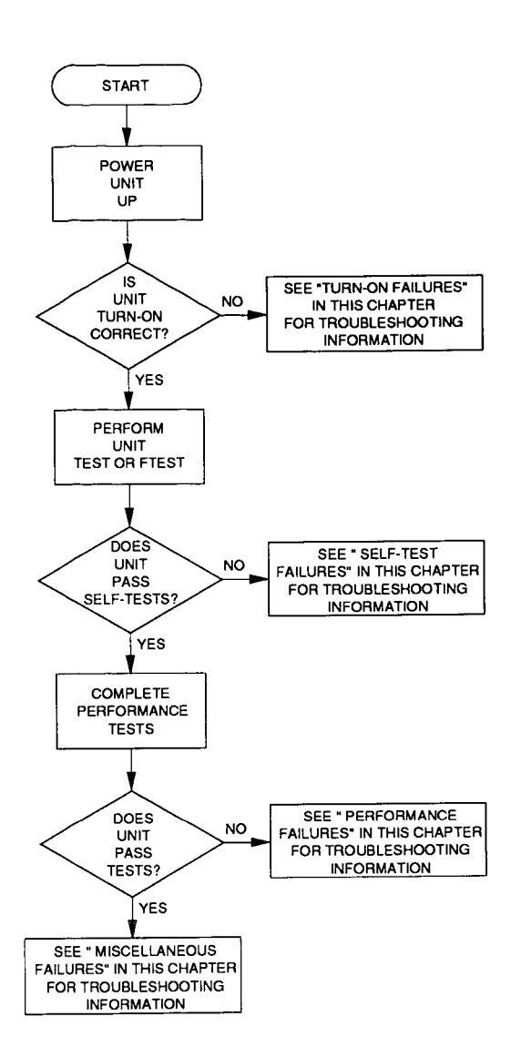
Figure 3-1. General Troubleshooting Diagram
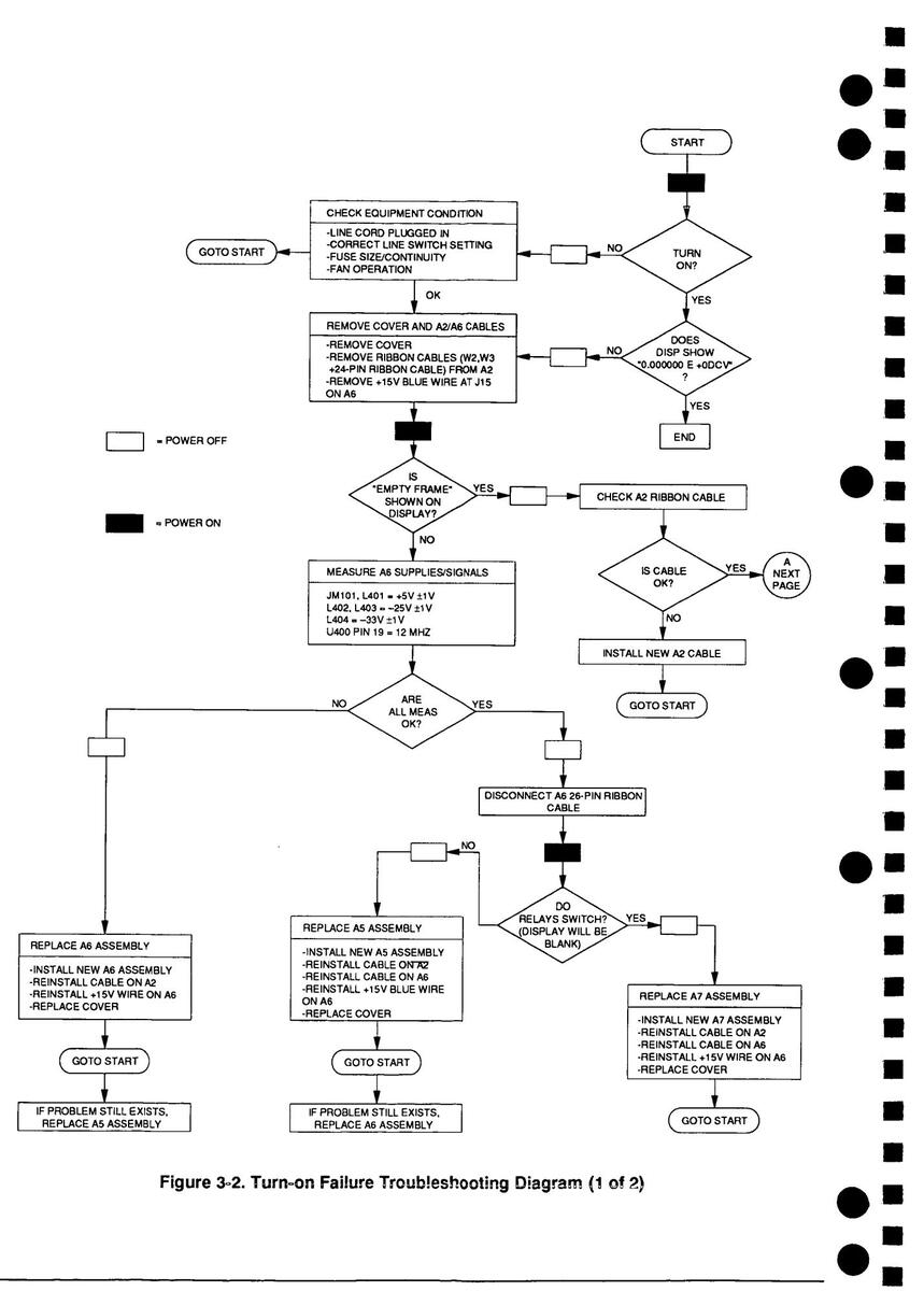
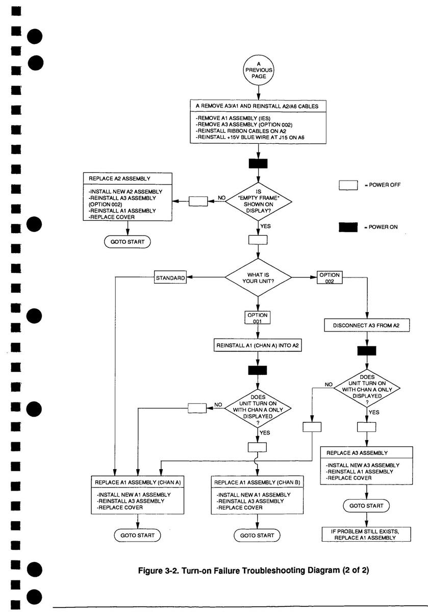
Turn-on Failures
A turn-on self-test is automatically executed upon instrument power up. This test is controlled by firmware residing in ROM on the A5 Outguard Logic PCA. Typical turn-on errors include: inoperative instrument with a blank display, inoperative instrument with unintelligible messages on the display, and operative unit with an error string in the display.
Turn the Universal Source power switch to on and verify that it beeps once, displays "TESTING ROM", displays "TESTING RAM", then relays switch and the display shows "0.000000E + 0DCV".
- If this sequence executes as described, proceed with "Self-test Failures" to continue troubleshooting.
- If this sequence is incorrect, follow the turn-on failure diagnostics tree in Figure 3-2 to isolate these errors to the assembly level.
Self-test Failures
Two individual self-tests can be executed if the Universal Source performs a successful turn-on: TEST and FTEST.
TEST TEST is used to provide a basic confidence check of the Universal Source, and does not change the instrument's current state or set-up. Executing TEST from the front panel checks the display panel, then each source module register that can be addressed without affecting the module's I/O state. During the display panel test, all of the normally used display elements are lit (except the shift annunciator). During the source module portion, if any register fails to respond the test fails. The source module busy times are checked and compared to an internal table of limit values, and the contents of the ID registers of the source modules that are stored in the CPU memory at power-on are read and compared. If there are any changes in these read values, the test will fail.
NOTES
TEST performs only a minimum set of routines. If instrument problems are suspected, FTEST should be performed to verify source module functionality. If TEST or FTEST is executed without designating a channel number (using HP-IB only), the first test will be the display panel test. The display panel test is not executed if channel numbers are included with the TEST command. Refer to Chapters 6 and 8 in the HP 3245A Universal Source Operating and Programming Guide for more information on TEST.
TEST is executed (from the front panel) by pressing the shift (blue key), then the TEST key on the front panel. PASS or FAIL is returned to the front panel display at the completion of the tests.
- If PASS is displayed, and there is still uncertainty about instrument functionality, FTEST should be performed.
- If FAIL is displayed, verify that Cable Assembly W2 is not the problem.
- If cable W2 is OK, replace the A5 Outguard Logic PCA (A5).
- If that fails to correct the malfunction, replace the Inguard Source PCA (A1).
- If that fails to correct the malfunction, replace the Backplane PCA (A2).
FTEST FTEST (fixtured test) is used to perform a full pass/fail functional test on the Inguard Source PCA specified.
NOTE
FTEST can be performed over the HP-IB interface or the Front Panel. Refer to Chapter 9 in the HP 3245A Universal Source Operating and Programming Guide for more information on the FTEST command.
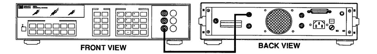
Connect a BNC cable from the channel under test to the trigger I/O port of the same channel. Execute the FTEST ch command, where ch is the channel under test (where 0 = front panel A; 1 = rear panel A; 100 = front panel B; 101 = rear panel B). PASS or FAIL is returned to the front panel display at the completion of the test. If fail is returned, the ERR$ is viewed by pressing the error key (! key) on the front panel.
Example: To test rear panel channel A connect channel A (rear) to the channel A trigger I/O on the front panel (as shown) and execute FTEST 1.
NOTE
Only the first four error messages are returned to the error buffer. Always troubleshoot the errors in the order given, as usually the first problem repaired will eliminate the rest.
- If PASS is displayed, repeat test for all channels.
- If FAIL is displayed after running FTEST 1 or FTEST 101, verify that relay A2K1 is not the problem. If the relay checks good, replace the Inguard Source PCA (A1) under test. If that fails to correct the malfunction, replace the Backplane PCA (A2).*
- If FAIL is displayed after running FTEST 0 or FTEST 100, replace the Inguard Source PCA (A1) under test.
|
Performance
Failures |
Performance test failures are problems that may not be detected during the turn-on and self-test procedures, but are detected during the performance tests.
Refer to Chapters 2 and 3 in the HP 3245A Calibration Manual for Operation verification and performance tests. |
|---|---|
| NOTE |
Before assuming that a performance test has failed, verify that the test equipment
and performance test methods have sufficient accuracy to check the instrument. The Universal Source is very accurate and needs appropriately accurate standards to verify specifications. Be sure to check the accuracy requirements before troubleshooting performance test failures. |
| If a performance test has failed: | |
| • Attempt a recalibration to correct the failed performance specification. | |
| • If recalibration does not correct the problem, replace the Inguard Source PCA (A1) under test. | |
| • Perform the turn-on, self-test, and failed performance test to verify that the performance problem has been corrected. | |
|
Miscellaneous
Failures |
If problems cannot be categorized as Turn-on, Self-test, or Performance
Failures, use the following information to troubleshoot the malfunction: |
| HP-IB PROBLEMS | |
| For HP-IB failures, check/clean all connector and interconnecting cable contacts. If malfunction remains, replace the A5 Outguard Logic PCA (A5). | |
| FAN PROBLEMS | |
| If the fan is not running, check the voltage at A6P3 for +15 Vdc. If +15V is present, replace the Fan (B1), otherwise, replace the Outguard Power Supply PCA (A6). |
DISPLAY PROBLEMS
For front panel display problems (e.g., lights, etc.) replace the Display Logic PCA (A7).
Assembly/Disassembly Procedures
•
Procedures are provided for disassembly and reassembly of the following items:
- Covers
- A1/A11 Inguard Source Printed Circuit Assembly
- A2 Backplane Printed Circuit Assembly
- A3 High Voltage Amplifier Printed Circuit Assembly (Option 002 only)
- A5 Outguard Logic Printed Circuit Assembly
- A6 Outguard Power Supply Printed Circuit Assembly
- A7 Display Logic Printed Circuit Assembly
| Reference Designator | Applies to Standard | Applies to Option 001 | Applies to Option 002 |
|---|---|---|---|
| A1 | YES | YES | YES |
| A2 | YES | YES | YES |
| A3 | NO | NO | YES |
| A5 | YES | YES | YES |
| A6 | YES | YES | YES |
| A7 | YES | YES | YES |
| A11 | NO | YES | NO |
WARNING
Capacitors inside the instrument may still be charged even if the instrument has been disconnected from its source of supply.
Tools Required
- #2 Pozi Drive
- #T-8 Torx driver
- #T-10 Torx driver
- #T-15 Torx driver
- 3/8 inch spin-tite
- 1/2 inch spin-tite
- 9/16 inch spin-tite
- 7 mm spin-tite
- 5/8 inch open-end wrench
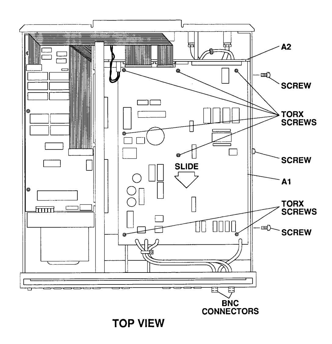
A1/A11 Inguard Source PCA
NOTE
.
There may be 1 (STD) or 2 (Option 001) Inguard Source PCA's installed in the Universal Source. The procedure for each is the same, however, the illustration only shows one installed.
2. Locate the three screws on the side of the instrument that retain the metal deck in place. Remove the outer two screws and loosen the center screw (see Figure 3-4).
3. Slide the metal deck/Inguard Source PCA(s)/optional A3 High Voltage Amplifier PCA (if installed) combination toward the front of the instrument to disengage the PCA(s) from the A2 Backplane PCA connectors.
NOTE
The connectors may require some force to disengage. Do not pry on the connectors or the Backplane PCA. If necessary, pry in one of the cutouts between the right side frame and the sheet metal deck.
4. Remove the BNC connectors from the front panel.
- 5. Remove the seven T10 screws and the A1 Inguard Source PCA(s).
- 6. Reverse order to reinstall the A1 Inguard Source PCA(s).
ł
Ľ
Figure 3-4. Remove and Replace A1/A11 Inguard Source PCA
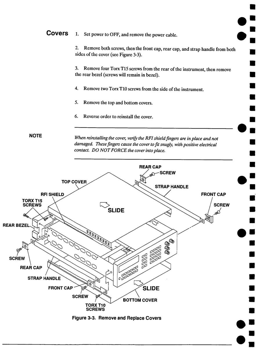
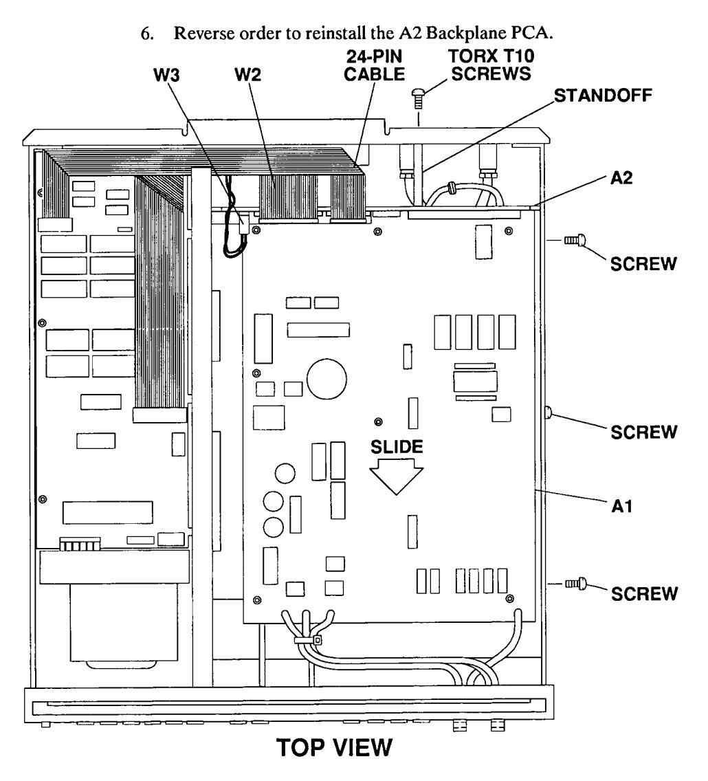
A2 Backplane PCA 1. Remove covers (refer to Figure 3-3).
a (
2. Disengage the connectors on the A1 Inguard Source PCA, and if installed the optional A3 High Voltage Amplifier PCA (refer to Figure 3-4 stens 2 and 3).
3. Disconnect W2, W3. and 24-pin cable assembly from the A2 Backplane PCA (refer to Figure 3-5).
Remove one Torx T10 screw, the two standoffs, and the A2 Backplane PCA. 4
Remove A2 Backplane PCA (standard) or A2 Backplane PCA/A3 High 5 Voltage Amplifier PCA combination (Option 002).

1. Remove covers (refer to Figure 3-3).
A3 High Voltage Amplifier PCA (Option 002 only)
2. Disengage the connectors on the A1 Inguard Source PCA/A3 High Voltage Amplifier PCA (refer to Figure 3-4 steps 2 and 3).
- 3. Disconnect coax cable assembly from A3 (refer to Figure 3-6).
- 4. Remove five Torx T10 screws and A3 High Voltage Amplifier PCA.
- 5. Reverse order to reinstall the A3 High Voltage Amplifier PCA.
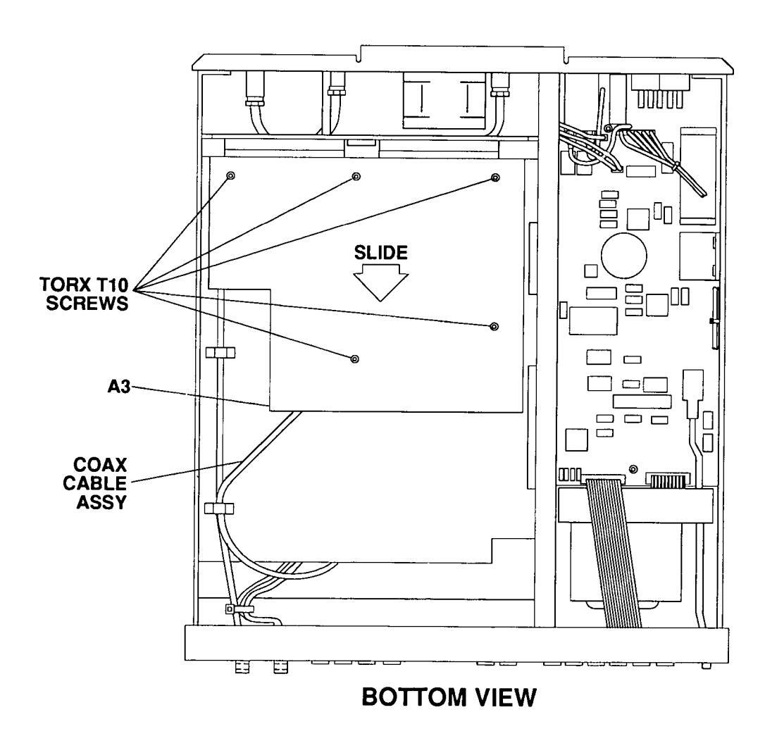
Figure 3-6. Remove and Replace A3 High Voltage Amp PCA
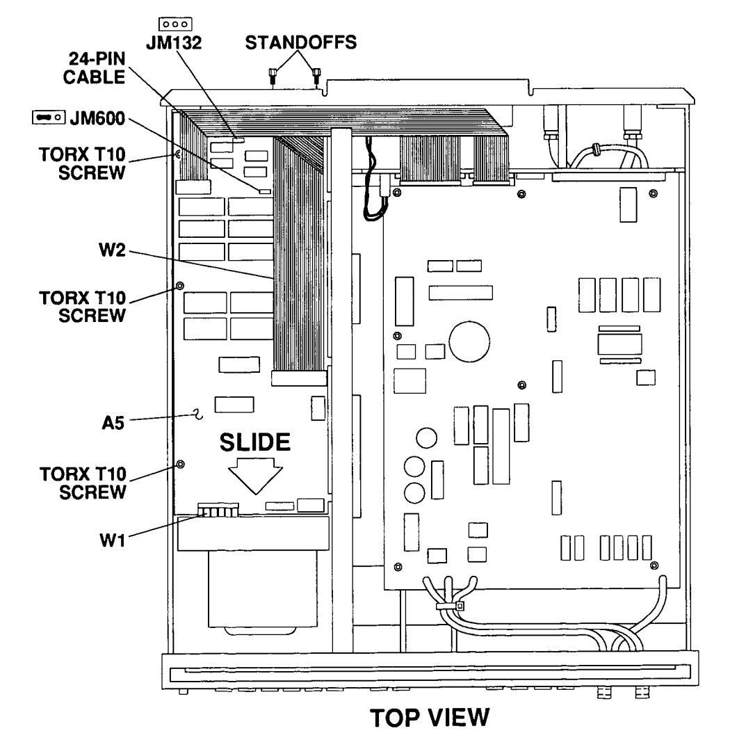
A5 Outguard Logic
1. Remove covers (refer to Figure 3-3).
2. Disconnect W1, W2, and 24-pin cable assembly from A5 Outguard Logic PCA (refer to Figure 3-7).
3. Remove three Torx T10 screws and two rear panel connector standoffs.
4. Slide A5 Outguard Logic PCA forward and lift out.
5. Reverse order to reinstall the A5 Outguard Logic PCA. If installing a new PCA, verify that jumper is not installed at A5JM132, and that jumper is installed at A5JM600 pins 1 - 2.

A6 Outguard Power Supply PCA
- 1. Remove covers (refer to Figure 3-3).
- 2. Remove the power switch actuator (refer to Figure 3-8).
3. Disconnect W1, 26-pin cable assembly, 8-pin cable assembly, 2-pin cable assembly, blue wire, and line filter wires (W3 and W4) from A6 Outguard Power Supply PCA.
4. Cut cable ties next to heatsink.
5. Remove two screws holding heatsink to side panel, and two Torx T15 screws retaining the A6 Outguard Power Supply PCA.
- 6. Slide and lift A6 Outguard Power Supply PCA out of the frame.
- 7. Reverse order to reinstall the A6 Outguard Power Supply PCA.
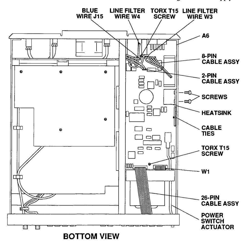
Figure 3-8. Remove and Replace A6 Outguard Power Supply PCA

| 47 | Display | Logic |
|---|---|---|
| DCA |
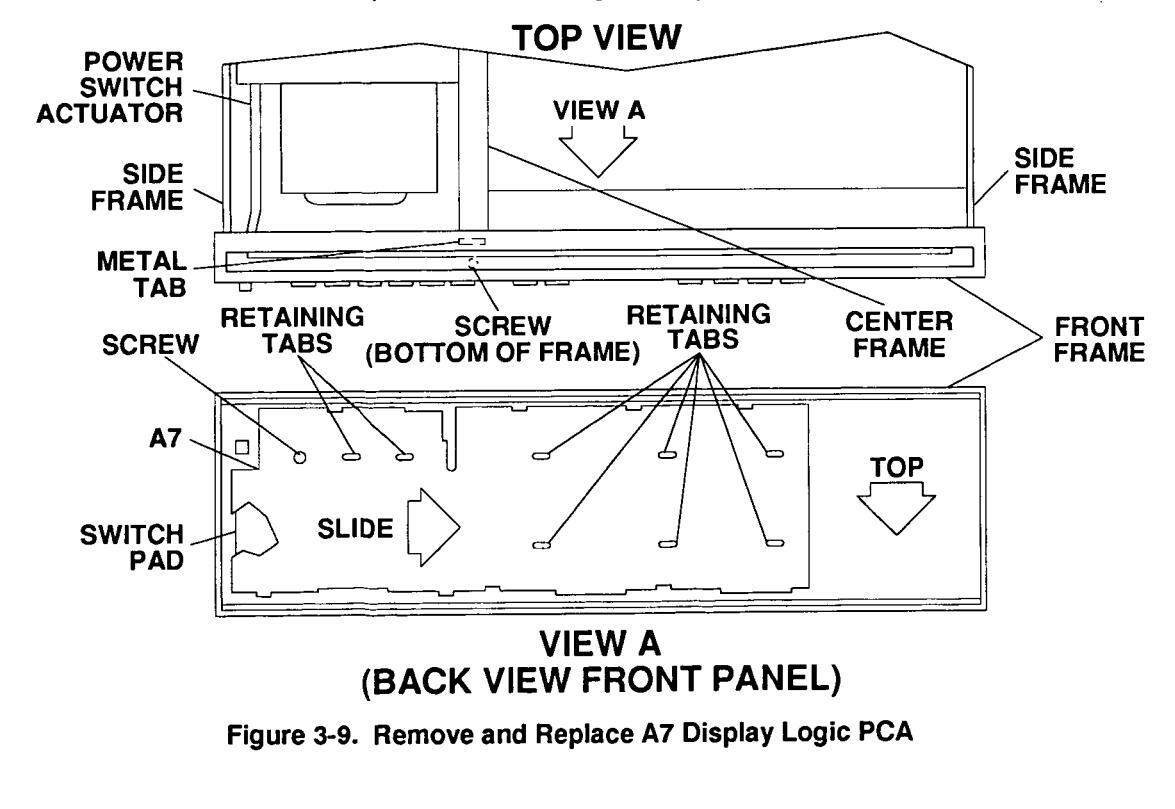
1. Remove covers (refer to Figure 3-3).
2. Remove A1/A11 Inguard Source PCA(s) (refer to Figure 3-4).
3. Remove the screw (located behind the front panel BLUE key) that holds the front panel to the center frame (refer to Figure 3-9).
4. Remove the power switch actuator.
5. Push the side frame in toward the center of the instrument until frame disengages from the front panel.
6. The center frame has a small metal tab that holds the front panel to the center frame. Lift the front panel away from the center frame small metal tab and move the front panel away from the center frame.
7. Remove the front panel from the other side frame.
8. Remove one screw and slide the A7 Display Logic PCA out of the retaining tabs.
9. Reverse order to reinstall the A7 Display Logic PCA. When reinstalling, verify that rubber switch pad is in place prior to replacing the PCA.
|
Repair and
Maintenance Guidelines |
This section provides guidelines for repairing and maintaining the HP 3245A
Universal Source including: |
|---|---|
|
|
| ESD Precautions |
Electrostatic discharge (ESD) may damage static sensitive devices in the
Universal Source . This damage can range from slight parameter degradation to catastrophic failure. When handling Universal Source assemblies, observe the following guidelines to avoid damaging the assemblies: |
| • Always use a static-free work station with a pad of conductive rubber or similar material when handling assemblies. | |
| • If a device requires soldering, be sure the assembly is placed on a pad of conductive material. Also, be sure that you, the pad, and the soldering iron tip are grounded to the assembly. | |
|
Soldering Printed
Circuit Boards |
The etched circuit boards of the Universal Source assemblies have plated-
through holes that provide a solder path to both sides of the insulating material. Soldering can be done from either side of the board with equally good results. When soldering to any circuit board: |
| • Avoid unnecessary component unsoldering and soldering. Excessive replacement can result in damage to the circuit board, adjacent components, or both. | |
| • Do not use a high-power soldering iron on etched circuit boards, as excessive heat may lift a conductor or damage the board. | |
| • Use a suction device or wooden toothpick to remove solder from component mounting holes. When using a suction device, be sure that the equipment is properly grounded. | |
|
Post-Repair Safety
Checks |
After making repairs to the Universal Source, inspect the instrument for any signs of abnormal internally generated heat, such as discolored printed circuit boards or components, damaged insulation, or evidence of arcing. Determine and correct the cause of the condition. Then perform the functional tests as described in Chapter 2 and 3 of the Calibration Manual to verify that the instrument is functional. |
HEADQUARTERS OFFICES If there is no sales office listed for your area, contact one of these headquarters offices
NORTH/CENTRAL AFRICA EASTERN USA
Hewlett-Packard Co
4 Choke Cherry Bood
ROCKVILLE, MD 20850
Hewlett-Packard Co
SOUTHERN USA
Hewlett-Packard Co.
ATLANTA, GA 30339
WESTERN USA
2000 South Park Place
Hewlett-raukard C.
MIDWESTERN USA
ROLLING MEADOWS IL 60008
NOPTH HOLLYWOOD CA 91601
AND MIDDLE FAST
32 Kifissias Ave
Tel: 682 88 11
AREAS
Hewlett-Packard Co
3495 Deer Creek Road
PALO ALTO, CA 94304
Telex: 034-8300
Cable: HEWPACK
Mediterranean and Middle East
Paradissos-Amarousion. ATHENS
Telex: 21-6588 HPAT GP
Cable: HEWPACKSA Athens
OTHER INTERNATIONAL
Intercontinental Headquarters
Hewlett-Packard S.A. 7, rue du Bois-du-Lan CH-1217 MEYRIN 1, Switzerland Tel: (022) 83 12 12 Telex: 27835 hmea Cable: HEWPACKSA Geneve
ASIA
ASIA Hewlett-Packard Asia Ltd. 47/F, 26 Harbour Rd., Wanchai, HONG KONG G.P.O. Box 863, Hong Kong Tel: 5-8330833 Telex: 76793 HPA HX Cable: HPASIAL TD
EASTERN EUROPE Hewlett-Packard Ges.m.b.h. Lieblgasse 1 P.O.Box 72 A-1222 VIENNA, Austria Tel: (222) 2500-0 Telex: 1 3 4425 HEPA A
NORTHERN EUROPE Hewlett-Packard S.A. V. D. Hooplaan 241 P.O.Box 999 NL-1183 AG AMSTELVEEN The Netherlands Tel: 20 547999 Telex: 18 919 boner
SOUTH EAST EUROPE Hewlett-Packard S.A. World Trade Center 110 Avenue Louis Casai 1215 Cointrin, GENEVA, Switzerland Tel: (022) 98 96 51 Telex: 27225 hpser
ARGENTINA
Argen TINA Hewlett-Packard Argentina S.A. Montaneses 2140/50 1428 BUENOS AIRES Tel: 781-4059/69 Cable: HEWPACKARG
AUSTRALIA
Hewlett-Packard Australia Ltd. 31-41 Joseph Street P.O. Box 221 BLACKBURN, Victoria 3130 Tel: 895-2895 Telex: 31-024 Cable: HEWPARD Melbourne
Hewlett-Packard Australia Ltd. 17-23 Talavera Road P.O. Box 308 NORTH RYDE, N.S.W. 2113 Tel: 888-444 Telex: 21561 Cable: HEWPAPD Sydpay
AUSTRIA Hewiett-Packard Ges.m.b.h. Liebigasse 1 P.O. Box 72 A-1222 VIENNA Tel: (0222) 2500-0 Telor: 104/25 VEDA A
BELGIUM Hewlett-Packard Belgium S.A./N.V. Bivd de la Woluwe, 100 Woluwedai B-1200 BRUSSELS Tel: (02) 762-32-00 Telex: 23-494 paloben bru
BRAZIL Hewlett-Packard do Brasil I.e.C. Ltda. Alameda Rio Negro, 750 ALPHAVILLE 06400 Barueri SP Tel: (011) 421.1311 Telex: (011) 33872 HPBR-BR Cable: HEWPACK Sao Paulo
Hewiett-Packard do Brasil I.e.C. Ltda. Praia de Botafago 228 6° Andar-conj 614 Edificio Argentina - Ala A 22250 RIO DE JANEIRO, RJ Tel: (021) 552-6422 Telex: 21905 HPBR-BR Cable: HEWPACK Rio de Janeiro
CANADA Hewlett-Packard (Canada) Ltd. 11120-178th Street EDMONTON, Alberta T5S 1P2 Tel: (403) 486-6666
Hewlett-Packard (Canada) Ltd. 17500 Trans Canada Highway South Service Road KIRKLAND, Quebec H9J 2X8 Tel: (514) 697-4232 Telex: 058-21521
Hewlett-Packard (Canada) Ltd. 6877 Goreway Drive MISSISSAUGA, Ontario L4V 1M8 Tei: (416) 678-9430 Telex: 069-8644
Hewlett-Packard (Canada) Ltd. 2670 Queensview Dr. OTTAWA, Ontario K2B 8K1 Tel: (613) 820-6483
CHINA, People's
China , People's Republic of China Hewlett-Packard Co., Ltd. P.O. Box 9610, Beijing 4th Floor, 2nd Watch Factory Main Bldg. Shuang Yu Shou, Bei San Huan Boad
SALES & SUPPORT OFFICES
Arranged alphabetically by country
Shuang Yu Shou, Bei San Huan Roa Hai Dian District BEIJING Tel: 28-0567 Telex: 22601 CTSHP CN Cable: 1920 Beijing
DENMARK Hewlett-Packard A/S Kongevejen 25 DK-3460 BIRKEROED
DK-3460 BIRKEROED Tel: (02) 81-66-40 Telex: 37409 hpas dk
FINLAND Hewlett-Packard Oy Pilspankalliontie 17 02200 ESP00 Tel: 00358-0-88721 Tele:: 121563 HEWPA SE
FRANCE Hewlett-Packard France Chemin des Mouilles Boite Postale 162 69131 ECULLY Cedex (Lyon) Tel: (78) 133-81-25 Telex: 310612E
Hewlett-Packard France Parc d'activités du Bois Briard Avenue du Lac 9 1040 EVRY Cedex Tel: (60) 77-83-83 Telex: 6923 15F
Hewlett-Packard France Zone Industrielle de Courtaboeuf Avenue des Tropiques 91947 LES ULIS Codex (Orsay) Tel: (69) 07-78-25 Telax: 600048F
GERMAN FEDERAL REPUBLIC Hewlett-Packard GmbH Vertriebszentrum Mitte Hewlett-Packard-Strasse D-6380 BAD HOMBURG Tel: (06172) 16-0 Fax: (06172) 16-1309
Hewlett-Packard GmbH Vertriebszentrun Südwest Schickardstrasse 2 D-7030 BÖBLINGEN Tel: (07031) 14-0 Fax: (07031) 14-6429
Hewlett-Packard GmbH Vertriebszentrum Süd Eschenstrasse 5 D-8028 TAUFKIRCHEN
D-8028 TAUFKIRCHEN Tei: (089) 61207-0 Fax: (089) 61207-300
GREECE Hewlett-Packard A.E. 178, Kifissias Avenue
Halandri-ATHENS
Greece Tel: 6471543, 6471673, 6472971 Telex: 221 286 HPHLGR
HONG KONG Hewlett-Packard Hong Kong, Ltd. G.P.O. Box 795
Sth Floor, Sun Hung Kai Centre 30 Harbour Road HONG KONG Tel: 5-8323211 Telex: 66678 HEWPA HX Cable: HEWPACK HONG KONG
ICELAND Hewlett-Packard Iceland Hoefdabakka 9 110 REYKJAVIK Tel: (1) 67 1000
INDIA Blue Star Ltd. 13 Community Center New Friends Colony NEW DELHI 110 065 Tel: 633182, 636674 Telex: 031-61120 Cable: BLUEFROST
INDONESIA BERCA Indonesia P.T. P.O.Box 2497/Jkt Antara Bidg., 11th Floor JI. Medan Merdeka Selatan 17 JAKARTA-PUSAT Tel: 343989 Telex: 46748 BERSAL IA
IRELAND Hewlett-Packard Ireland Ltd. 82/83 Lower Leeson Street DUBLIN 2 Tel: 0001 608800 Telex: 30439
ISRAEL Computation and Measurement Systems (CMS) Ltd. 11 Masad Street 67060 TEL-AVIV Tel: 388 388 Telex: 33569 Motil IL
ITALY
Hewlett-Packard Italiana S.p.A. Via G. di Vittorio 9 I-20063 CERNUSCO SUL NAVIGLIO (Milano) Tel: (02) 923691 Telex: 334632
Hewlett-Packard Italiana S.p.A. Vlale C. Pavese 340 I-00144 ROMA EUR Tel: (06) 54831 Telex: 610514
JAPAN Yokogawa-Hewlett-Packard Ltd. Chuo Bldg., 4 20 Nichinakajima 5 Okama
4-20 Nishinakajima, 5 Chome Yodogawa-ku OSAKA, 532 Tel: (06) 304-6021 Telex: YHPOSA 523-3624
Yokogawa-Hewlett-Packard Ltd. 29-21 Takaldo-Higashi, 3 Chome Suginami-ku TOKYO 168 Tel: (03) 331-6111 Telex: 232-2024 YHPTOK
Yokogawa-Hewlett-Packard Ltd. Yasuda Seimei Nishiguchi Bldg. 30-4 Tsuruya-cho, 3 Chome Kanagawa-ku, YOKOHAMA 221 Tel: (045) 312-1252


SALES & SUDDORT OFFICES Arranged alphabetically by country
KOREA
Samsung Hewlett-Packard Co. Ltd. Samsung newiett-rackaru ur Dongbang Yeoeuido Building 12-16th Electro 36-1 Yeoeuido-Dona Youngdeungno-Ku Tel: 784-4666 784 2666 Telex: 25166 SAMSAN K
MALATSIA Hewiett-Packard Sales (Malavsia) Sdn Bhd Chung Khiaw Bank Building 50350 KUALA LUMPUR Tel: 2986555
MEVICO
Hewiett-Packard de Mexico Monte Pelvoux No. 111 Monte reivoux nu. 11 11000 MEXICO. D.F. Tel: 5-40-62-28, 72-86, 50-25 Telex: 17-74-507 HEWPACK MEX
Hewiett-Packard Nederland B V Starthaan 16 Startbaan in NI _1187 YR AMSTELVEEN P.O. Box 667 P.O. BOX 667 NL-1180 AR AMSTELVEEN Tel: (020) 547-6911 Telex: 13 216 HEPA NI NORWAY
Hewlett-Packard Norge A/S Osterndalen 16-18 P.O. BOX 34 N-1345 DESTERAAS Telex: 76621 hpnas n
PUERTO RICO Hewlett-Packard Puerto Bico 101 Munoz Rivera Av HATO REY, Puerto Rico 00918 Tel: (809) 754-7800
SAUDI ARARIA
Modern Electronics Establishment Hewlett-Packard Division P.O. Box 1228 Redec Plaza, 6th Floor JEDDAH Telex: 4027 12 FARNAS SJ Cable: ELECTA JEDDAH
SINGAPORE
Pte. I td #08-00 Inchcape House 450-2 Alexandra Rosc Alexandra P.O. Box 58 SINGAPORE. 9115 Tel: 4731788 Telex: 34209 HPSGSO RS Cable: HEWPACK, Singapore
SOUTH AFRICA
Hewlett-Packard So Africa (Pty.) Ltd. 9 Eastern Service Road Eastgate Ext. 3 SANDTON 2144 Tel: 802-5111 802-5125 Cable: HEWPACK Johannesburg
Howlett-Packard Fanañola, S.A. Crta de la Coruña, Km. 16, 400 Tel: (1) 637 00 11 Telar: 23515 HPF
SWEDEN Hewlett-Packard Sverige AB Skelholtsoatan 9 Kisto Dov 19 S 1000 column
Tel: (08) 750-2000 Telev: (954) 17996 Telefax: (08) 7527781 QWITZEDI AND
Hewlett-Packard (Schweiz) AG 7, rue du Bois-du-Lan Case nostale 365 CH-1217 MEYRIN 1 Tei: (0041) 22-83-11-11 Telev-27333 HDAC CU
Hewlett-Packard Taiwon I td 8th Floor, Hewlett-Packard Building 337 Fu Hsing North Road TAIPEI Tel: (02) 712-0404 Tolov: 24420 UEMOACK Cable HEWPACK Tainel
THEFEY Teknim Company Ltd. Textim Company i Karaklidere ANMADA Tel: 275800 Telex: 42155 TKNM TO
ENGLAND
Hewiett-Packard Ltd Heathside Park Road Cheadle Heath STOCKPORT Cheshire fel: 061-428-0828 Telex: 668068
Hewlett-Packard I to King Street Lane Winnersh WOXINGHAM Tel: 0734 784774 Telex: 847176 SCOTLAND
Hewlett-Packard I td SOUTH QUEENSFERRY West Lothian, EH30 9TG Hewlett-Packard Singapore (Sales) Tel: 031 331 1188 Telex: 72682
UNITED STATES
Alabama Hewlett-Packard Co
HUNTSVILLE AL 35805 Tel: (205) 830-2000
Arizona Hewlett-Packard Co. 8080 Pointe Parkway West PHOENIX. AZ 85044 Tel: (602) 273-8000 California Hewlett-Packard Co. 1421 S. Manhattan Av FULLERTON, CA 92631 Tel: (714) 999-6700
Hewlett-Packard Co 5651 West Manchester Ave LOS ANGELES CA 90045 Telev: 010 337-6000
Hewlett-Packard Co. 9606 Aero Drive SAN DIEGO CA 00100 Tel: (619) 279-3200
Hewlett Backard Co 3003 Scott Boulevard SANTA CLARA. CA 95054 Tel: (408) 988-7000 Telex: 910-338-0586
Colorado Hewiett-Packard Co. 24 Inverness Place. East ENGLEWOOD CO 80112 Tel: (303) 649-5000
Connecticut Hewlett-Packard Co 47 Barnes Industrial Road South WALLINGEORD CT 06402 Tel: (203) 265-7801
Florida Hewlett-Packard Co. 2901 N.W. 62nd Street FORT I AUDERDALE. FL 33309 Tel: (305) 973-2600
Hewlett-Packard Co. 6177 Lake Filenor Drive ORLANDO, FL 32809
Georgia 2000 South Park Place ATLANTA GA 20220 Teley: 810-766-4890
Illinois Hewlett-Packard Co. 5201 Tollview Drive ROLLING MEADOWS, IL 60008 Tal: (312) 255-0800 ⊤ज. (उ.1∠) ∠३३-७800 Telex: 910-687-1066 Hewlett-Packard Co. 11911 N. Meridian St.
CARMEL IN 46032 Tel: (317) 844-4100 Louisiana
Hewlett-Packard Co ST. ROSE. LA 70087 KENNER. LA 70063 Tel: (504) 467-4100
Marvland Hewlett-Packard Co. 3701 Konners Street BALTINORE, MD 21227 Telex: 710-862-1943
Hewlett-Packard Co 2 Choke Cherry Road Tel: (301) 948-6370
Massachusetts Hewiett-Packard Co. 1775 Minuteman Road ANDOVER, MA 01810 Tel: (617) 682-1500
Michigan
Hewlett-Backard Co. 39550 Orchard Hill Place Drive 39550 Orchard | NOVI. MI 48050 NUTI, MI 46030 Tal: (313) 349, 0300
Minnesota Hewlett-Packard Co.
Hewlett-Packard CC. 2025 W. Larbenteur Ave. 2025 W. Larpenteur / ST. PAUL, MN 55113 51. PAUL, MN 55113 Missouri
Hewlett-Packard Co. Hewlett-Packard Co. 1001 E. 101st Terrace Suite 120 KANSAS CITY MO 64121 2269
Hewlett-Packard Co Hewlett-Packaro Co. 13001 Hollenberg Drive BRIDGETON, MO 63044 Tel: (314) 344-5100
New Jersev Hewlett-Packard Co. 120 W Century Road PARAMUS, NJ 07653 Tel: (201) 265-5000
New Mexico Hewiett-Packard Co. 7801 Jefferson N E ALBUQUEROUE NM 87109
New York Hewlett-Packard Co. 9600 Main Street
Hewlett-Packard Co. 7641 Henry Clay Blud LIVERPOOL NY 13088
3 Crossways Park Wes WOODBURY, NY 11797 Tel: (516) 682-7800
North Carolina Hewlett-Packard Co. 5605 Roanne Way GREENSBORD, NC 27420 Tel: (919) 852-1800
Ohio Hewlett-Packard Co. 15885 Sprague Road Tel: (216) 243-7300
Hewlett-Backard Co 9080 Springhoro Pike MIAMISBURG, OH 45342 Tel: (513) 433-2223
Hewlett-Packard Co. 675 Brooksedge Blvd. WESTERVILLE, OH 43081 Tel: (614) 891-3344
Oklahoma 3525 N.W. 56th St OKLAHOMA CITY, OK 73112 Tel: (405) 946-9499
Oregon Hewlett-Packard Co. 9255 S. W. Ploneer Court WILSONVILLE OF 97070
Pannevivenie
Hewlett-Packard Co. 111 Zeta Drive PITTSBURGH PA 15238 Tel: (412) 782-0400
Howlett Beekerd Co. 2750 Monroe Boulevard VALLEY FORCE DA 19482
Teres I EXAS Hewiett-Packard Co. 1826-P Kramer Lane AUSTIN TY 79759 Tel: (512) 835-6771
Hewlett-Packard Co. 10535 Harwin Drive HOUSTON, TX 77036 Tel: (713) 776-6400
--------------------------------------930 E. Campbell Rd. RICHARDSON TY 75081 HICHARDSON, 1X 754 Tel: (214) 231-6101
Hewlett-Packard Co 1000 Central Parkway South SAN ANTONIO TY 78222 Tel: (512) 494-9336
Utah Hewlett-Packard Co 3530 W 2100 South St SALT LAKE CITY. UT 84119
Virginia 4205 Cov Road GIEN ALLEN VA 22060 Tel: (804) 747-7750
Washington Hewlett-Packard Co. 15815 S F 37th Street BELLEVILE MAN ORODE Tel: (206) 643-4000
Wiesessie Hewlett-Packard Co. 275 N. Corporate Dr. KFIELD, WI 53005 Tel: (414) 794-8800
VENEZUELA 3A Transversal Los Ruices Norte Edificio Segre 2 & 3 Apartado 50933 CARACAS 1050 Tel: (582) 239-4133 Telex: 251046 HEWPACK
YUGOSLAVIA VIL-11000 REOGRAD Tel: (011) 342 641 Telex: 11433

Copyright © 1992 Hewlett-Packard Company Printed in U.S.A. October 1992 E1092


 Loading...