

Page 1
Media Path for a Small, Low-Cost,
Color Thermal Inkjet Printer
The DeskJet 1200C media path is heated for media independence,
requiring development of a new grit drive roller and pinch wheel
combination. A new stepper motor was developed to attain the target
speed and accuracy. Media flatteners and precise gearing with an
antibacklash device contribute to accuracy.
by Damon W. Broder, David C. Burney, Shelley I. Moore, and Stephen B. Witte
The media path is the part of a printer that moves media
past the print cartridges, stopping and accurately locating
the media for printing. The media path also constrains the
media in a plane a fixed distance from the print cartridges. A
media path should advance media accurately and quickly, be
quiet, be inexpensive, hold the media flat, and keep the media
the correct distance from the print cartridges.
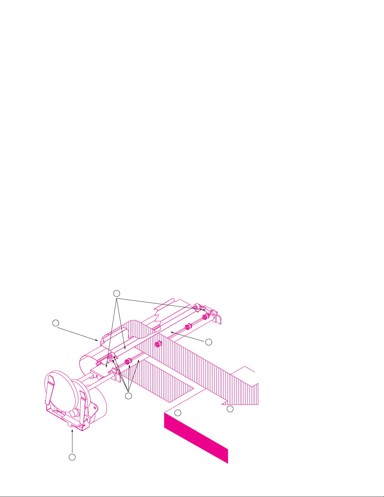
Fig. 1 shows an overview of the media path of the HP DeskJet 1200C printer. Media stacked in the input tray (1) is individually picked by a media pick roller (not shown) and
driven around the curved preheat zone (2) where it is preconditioned (moisture is driven off and the temperature is
raised). When the page reaches the pinch/drive rollers (3),
the main drive system (4) takes over from the pick roller
drive (not shown). Once in the print zone (5) the media is
heated further and ink is sprayed onto the page. The heating,
soaking, and drying causes the media to move out of its
Paper Control Shims
6
Preheat Zone
2
3
Pinch/Drive
Rollers
Main Drive System4
Input Tray
1
plane, but the media control shims (6) help hold it flat for
better print quality. The page is then incrementally advanced
and printed upon until the entire page has been printed.
Finally, the page is fed out into the output tray (7) and the
process is ready to repeat.
Design Approach
For the office printer market, the DeskJet 1200C is designed
to support a wide variety of plain papers, to be HP LaserJet
printer compatible, to print text very quickly, to print highquality graphics, and to be cost competitive. These characteristics forced the design team to face the following challenges:
• Constrain plain papers flat even though plain paper tends to
cockle and curl in various directions when ink is sprayed on
and heated.
• Print to 50-dot row margins for LaserJet compatibility, even
though such small margins allow very little control over
media flatness.
Fig. 1. Overview of the media
path of the HP DeskJet 1200C
printer. Media stacked in the input
tray (1) is individually picked by
a media pick roller (not shown)
and driven around the curved
Print Zone
5
Media Direction
7
Output Tray
preheat zone (2) where it is preconditioned (moisture is driven
off and the temperature is
raised). When the page reaches
the pinch/drive rollers (3), the
main drive system (4) takes over
from the pick roller drive (not
shown). Once in the print zone
(5) the media is heated further
and ink is sprayed onto the page.
The heating, soaking, and drying
causes the media to move out of
its plane, but the media control
shims (6) help hold it flat for better print quality. The page is then
incrementally advanced and
printed upon until the entire page
has been printed. Finally, the
page is fed out into the output
tray (7) and the process is ready
to repeat.
72 February 1994 Hewlett-Packard Journal
Page 2
• Move media very quickly through the print area while main-
taining high placement accuracy for good graphics print
quality.
• Keep the price low.
The parts of the media path (Fig. 1) that drive and meter the
media include the stepper motor, the drive pinions, the drive
gears, the antibacklash device, the shaft bushings, the adjustable plate, the drive rollers, and the pinch rollers. While
driving the media these components work together to ensure fast, accurate movement of the print media, which in
turn provides the best possible throughput.
The stepper motor provides the fastest response available in
an inexpensive motor. Although stepper motors aren’t always the most accurate type of motor, the accuracy of the
system can be optimized by designing the system so that the
motor always moves in multiples of four half steps. Moves
of four half steps cancel out all of the error caused by manufacturing variation except the locations of the stator teeth
which are formed out of the sheet-metal case of the motor.
Used in this way, the stepper motor can provide very fast
and accurate moves and is well-suited for driving the media
in an inkjet printer.
The gearing system in the DeskJet 1200C is designed to optimize the accuracy of the media drive. A single-reduction drive
is used because there are fewer components in the gear train,
so this type of drive is more accurate. However, accuracy is
not the only reason to use a single reduction. The size and
spacing of the drive rollers relative to the print cartridges and
heater also pushed the design towards a single-reduction
gear train. The DeskJet 1200C relies on a heated media path
to dry the ink as it is being printed. To make room for the
heater while maintaining control of the print media, the drive
rollers had to be much smaller than other inkjet printers had
typically used. By using smaller drive rollers, we were able
to use a single-reduction gear train.
The spacing of the drive rollers was a critical issue in the
design of the DeskJet 1200C. The spacing is constrained by
the size of the print cartridges and heater. Thus, we had to
trade off room for the heater and print cartridges against
control over the leading edge (the star wheels hold the media down against the output drive roller) and print quality in
the bottom margins (the main drive roller is more accurate
than the output drive roller). As the space between the rollers increases, there is a longer span of media at the top of
the page to control with the star wheels and a longer space
at the page bottom where the media is driven by the output
roller.
A major problem in reducing the shaft spacing was reducing
the size of the drive roller. Drive rollers in inkjet printers
have typically been rather large elastomer-coated shafts, 40
to 70 mm in diameter. To shrink the roller to a size we could
use (20 mm) we had to find a different process, one that
was new to inkjet printing. We decided to try the grit drive
system used in several HP plotters, which consists of a gritcoated metal drive wheel and an elastomer pinch wheel. By
using a grit system, we could minimize manufacturing errors
associated with the size and shape of elastomer rollers and
reduce the size to one we could use. Of course, we then faced
many problems adapting the grit drive system to a heated
media path system.
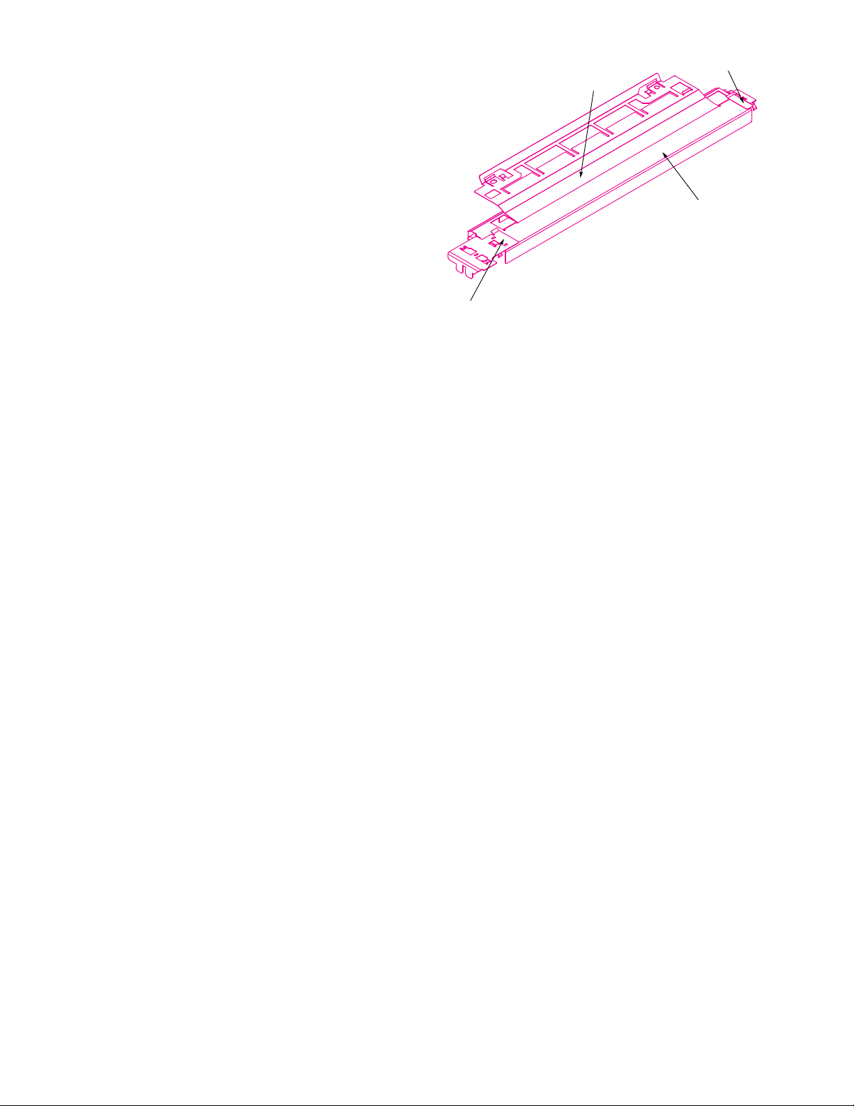
Right Shim
Center Shim
Grill
Left Shim
Fig. 2. A grill and three shims hold the media flat in the print zone.
The media path must also hold the print media flat. The environment in the print region is somewhat hostile to paper.
The ink soaks the paper, and the heater boils the water out
of the paper and dries it out. The DeskJet 1200C is intended
to print on any office paper with nearly equal print quality.
The heater and the ink design help achieve media independence, but at the same time, the heater and ink wreak havoc
with the fibers that make up the paper. The fibers, predominantly cellulose, swell with ink and the paper expands.
Then, as the paper is heated and dried, the fibers shrink and
the media contracts. None of the expansion and contraction
is uniform from one side of the media to the other, so the
media tends to move out-of-plane. To print with high quality,
the distance from the print nozzles to the print media must
be accurately maintained. We hold the media flat against a
grill (which covers the heater) with three shims—center,
left, and right, as shown in Fig. 2. The fixed right shim constrains the right edge of the media and acts as the zero reference point for printing. The adjustable left shim adjusts to A
and A4 sizes while constraining the left edge of the media.
The center shim helps keep the media flat against the grill
and helps keep the media from crashing into the print cartridge. The center shim also allows printing very near the
bottom edge of the media—as close as 5 mm.
As the paper advances out of the print region, we also hold
it down with the star wheels. These systems provide good
control over the media, keeping it constrained in a plane at a
fixed distance from the print nozzles.
Heated Media Path
The DeskJet 1200C was envisioned to support a broad range
of media: not just A and A4 sizes, but also glossy paper,
transparency film, and virtually any paper on the market (at
one point we were even printing on paper bags). With such a
wide range of media as the goal, and the added challenge of
fast throughput, it became evident that the DeskJet 1200C
would need a heated media path to meet these goals with
any kind of reasonable print quality.
The heated media path of the DeskJet 1200C (see Fig. 3) is
composed of two main components: the preheater and the
main heater. The preheater is a flexible polyimide heater
that serves as the inner guide for the media. As the media is
February 1994 Hewlett-Packard Journal 73
Page 3
Preheater
Main Heater
Fig. 3. Heated media path.
Writing Zone
fed up into the main heater and the writing zone, it is
wrapped around the preheater. This contact allows the preheater to precondition the media so that when the media
reaches the writing zone it is much more dimensionally
stable. Much of the paper fiber shrinkage that occurs with
heating happens before the paper reaches the writing zone.
The main heater consists of a Kanthal wire and a quartz
tube. Current drawn through the wire causes it to heat up
and emit infrared radiation. The radiation and convective
heat from the bulb help evaporate the water from the ink in
the writing zone. This increase in the evaporation rate of the
ink allows increased throughput and improved print quality
over a much broader range of media.
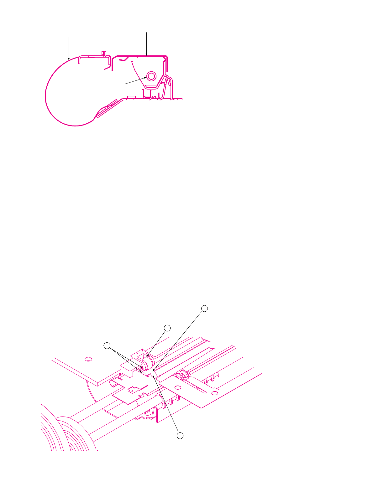
Drive Roller Development
The DeskJet 1200C media advance is controlled by a highpressure nip concept (drive roller and pinch wheel) located
near the left and right media margins (Fig. 4). As mentioned
earlier, this gives a clear advantage in space conservation
and design simplicity over other inkjet products using largediameter drive rollers and low-pressure nip concepts.
A traction surface designed to tolerate thermal shock with a
low thermal expansion needed to be developed. The lowcost, high-quality advance mechanism goals also required a
reliable manufacturing process that would produce 100%
in-specification parts.
The traction surface characteristics were initially defined
from a customer satisfaction viewpoint:
• The combination of nip pressure and drive roller roughness
could not mar transparencies or leave tracks in plain paper.
• The traction surface had to push the media with no slippage.
• Banding had to be controlled much more tightly than before
to meet print quality expectations. This meant that the traction surface had to advance the media consistently a constant distance for a given arc of rotation, that is, the pitch
diameter had to be as tightly controlled as technology would
permit. The printer’s performance could not be adjusted to
compensate for poor control of this specification in manufacturing. Print quality swath banding has a 1:1 correlation
with this assembly.
• The cost had to be low and the process compatible with
high-volume manufacturing.
• The materials selected had to survive with no degradation
of their properties within the thermal operating environment
of the printer.
A fundamental design goal for the Deskjet 1200C drive roller
assembly was to develop a roller surface that would not slip
on any media type. This was approached from a mechanical
friction and traction point of view. Lab tooling adequate to
characterize the traction surface had to be developed quickly.
The reality of our schedule required high-risk decisions with
data lagging by several months.
Concurrent development was started for lab tools, prototypes, and metrics simultaneously. We had to allow the development of the drive roller assembly to slip out of phase
with the rest of the project and get convergence by the time
of the production build.
1
74 February 1994 Hewlett-Packard Journal
3
2
Fig. 4. Drive roller and pinch
wheel. (1) Nip area (drive roller
and pinch wheel), one of two in
the printer. (2) Pinch wheel. The
pinch wheel rolls on the media
above the drive roller to apply
normal loading of the media into
the traction surface of the drive
roller. (3) Drive roller. Rotary
motion of the drive train is converted to linear media motion.
The surface must not slip or leave
tracks in the media. (4) Pitch diameter is twice the radius from
4
the drive axle center of rotation
to the contact zone between the
media and the traction surfaces.
Page 4

Stepper Motor Simulation Model
The model used to simulate a permanent magnet stepper motor for the simulations
described in the accompanying article originated from a classic control systems
point of view. The model includes simple position and velocity feedback control
algorithms. Fig. 1 is a block diagram of the model.
A nonlinear block in the model allows the nonlinear characteristics of the stepper
to be included. This block makes the stepper torque output match the desired
torque for a given error signal.
The resultant nonlinear system was linearized by running it at a very high sample
rate of 40,000 samples per second. At this sample rate, speeds, positions and
currents are changing very slowly. Hence linear control systems analysis is valid.
The model was used to compute velocity profiles with several different motor
resistances, inductances, and so on. The lowest-resistance motor available in a
permanent magnet motor at this time was an 8-ohm motor. Fig. 2* shows that the
Nonlinear Stepper Simulator:
Reference
Generator
Reference
Position
Error
(Torque
+
Desired)
–
Coil Resistance and Inductance
Current Level Maximum
Holding Torque Maximum
Back EMF Feedback
Optimum Switching Time to Match Desired Torque
Half-Stepping and Full-Stepping Modes
simulated velocity clearly does not reach the desired 1400 steps per second. This
motor fails and stalls in the real system. In Fig. 3,* the simulated velocity of a
2-ohm motor is shown. In this successful run, it appears that the motor has no
trouble reaching the desired 1400 steps per second. This motor was built and is
now the motor being used in the DeskJet 1200C printer.
The curre n t s i n a failing stepper motor are shown in Fig. 4* and the currents in a
stable, running stepper motor are shown in Fig. 5.* In the failing stepper motor, the
currents do not even reach their normal operating levels before they are switched
again. The characteristic hook in the graph of these currents reflects reality very
well for the case of insufficient voltage used to drive the motor.
Stephen B. Witte
Development Engineer
San Diego Printer Division
Torque
Delivered
Linear Plant Differential Equations:
Moment of Inertia of Motor and Gears
Acceleration and Velocity of Rotor
Friction
Digital Filter:
Position and
Velocity
Feedback
Sample Time 25 Microseconds
Position
Response
Fig. 1. Block diagram of the theoretical stepper motor model.
The term traction was used to define media slippage with the
drive surface to avoid preconceptions of friction behavior.
(Paper has a composite surface of fibers and fillers that cause
its frictional characteristics to be nonlinear with normal
forces beyond a relatively low surface shear stress.)
The characterization efforts revealed interactions with printer
components not previously considered. Affected components
were redesigned and the traction surface successfully developed in concert with these components. Analytical tools to
measure system and component performance were developed or enhanced by this project. This greatly improved correlation of print quality goals with measured performance
and design specifications.
High-volume processes at multiple suppliers for this assembly
were characterized with proven process margins. Supplier
inspection processes were improved to fit part requirements
and inspection metrics.
Media Motor and Antibacklash Device
The goal for selecting the Deskjet 1200C media axis drive
was to design a motor and gearing system that is simple and
compact and has better speed and accuracy than we had
* See top of next page for Figs. 2, 3, 4, and 5.
ever achieved before. Not only did this new gear drive system
have to have improved performance, but it also had to be
less expensive.
One key element of the media drive system is the motor
selection. The HP PaintJet, PaintJet XL, and PaintJet XL 300
printers use a hybrid stepper motor to drive gear trains that
control two roller media drive systems. These systems have
relatively high inertia and are limited in speed. They also
have multiple idler gears for the purpose of transferring
position control to a different location in the machine. For
the HP DeskJet 1200C printer, a decision was made to use a
double-pinion approach to eliminate the idler gears.
For low cost, we believed that a permanent magnet stepper
combined with an antibacklash device would be as accurate
as the hybrid stepper system. The key issues were: How do
we design a low-cost anti-backlash device? and, How do we
get the speed and torque that we need out of this low-cost
stepper motor?
To determine whether the permanent magnet stepper would
work, a theoretical model was developed that allows the
simulation of the motion of a stepper motor from a standing
February 1994 Hewlett-Packard Journal 75
Page 5

1600
1400
1200
1000
800
600
Velocity (steps/s)
400
200
0
–200
0 0.005 0.01 0.015 0.02 0.025
Time (seconds)
0.8
0.6
0.4
0.2
0
–0.2
Current (amperes)
–0.4
–0.6
–0.8
0 5 10 15 20 25
Time (ms)
30
Fig. 2. Simulated velocity profile of a failing motor (8-ohm).
1600
1400
1200
1000
800
600
Velocity (steps/s)
400
200
0
–200
0 0.005 0.01 0.015 0.02 0.025
Time (seconds)
Fig. 3. Simulated velocity profile of a good (2-ohm) motor.
start through high speed and back down to a stop (see
“Stepper Motor Simulation Model” on page 75). This model
includes the motor, system inertia, inductance, motor resistance, and friction. It also dynamically calculates backEMFs and motor currents.
This simulation predicted that a motor with a resistance of
one or two ohms could run significantly faster than previous
DeskJet motors. Speeds of 2000 full steps per second (2500
r/min) were predicted as possible high-end speeds where
older permanent magnet motors had not been run much
faster then 600 to 1000 steps per second.
A motor vendor was located that would be willing to wind
the motor coils with a heavy-gauge wire and prototype
motors were assembled. These motors performed at the
predicted speeds and astounded the motor R&D engineers
themselves! They previously had not built permanent magnet steppers with this kind of speed capability. This vendor
developed manufacturing processes to produce these lowresistance coils in production and ultimately won the contract to provide HP with these motors for the Deskjet 1200C
printer.
Fig. 5 shows the complete motor, gears, and backlash system.
Fig. 4. Simulated currents in a failing motor.
1.5
1
0.5
0
Current (amperes)
–0.5
–1
–1.5
0 5 10 15 20 25
Time (ms)
Fig. 5. Simulated currents in a stable, running stepper motor.
Fig. 5. The complete motor, gears, and backlash system.
30
76 February 1994 Hewlett-Packard Journal
Page 6

Reducing Stepper Noise. Once we had the speed that we
needed, we had several more hurdles to pass. It was necessary to control the motor and make it start and stop precisely without the noises that normally come from stepper
motors. When the first DeskJet 1200C lab prototypes were
built, people were very concerned about the stepper noise.
Hardware was developed that allows the dynamic response
of both the motor and the gear-driven shaft to be measured.
This hardware was combined with personal-computer-based
software that makes the process of smoothing out the step
profile of the motor relatively easy. Because the designers
had been clever enough to make it easy to download step
times to the printer, it was possible to try out different combinations of step times quickly and observe the response of
the motor and drive shaft visually (in addition to hearing it).
The dynamic response was successfully smoothed out and
the system became much quieter. At the same time, we were
also anticipating problems with overshoot.
Controlling Backlash. Fig. 6 shows the function of the antibacklash device. The purpose of this sheet-metal spring is to
keep the teeth of the gears meshed tightly even if the motor
backs up slightly. If the gears were to become unmeshed,
the resultant accuracy error would be twice as much as all
other error sources combined.
The DeskJet 1200C media axis completes a 1/3-inch swath
advance in under 58 milliseconds. (For comparison, the
PaintJet XL300 completes a 1/6-inch swath advance in about
200 milliseconds.) Hence, it was expected that it would be
difficult or impossible to prevent gear backlash. However,
we came up with a way to reduce this backlash. The idea is
to use a piece of sheet-metal steel that pinches the gears,
adding friction so that when the motor stops and backs up,
the gears follow it backwards. This steel antibacklash device
has three springs built into one component. The first spring
applies a controlled pinch force on the gear. The second
spring is stretched forward every time the motor moves forward and provides the restoring force or antibacklash function. The third spring provides a thrust load that keeps the
plastic gears pushed against the motor mounting plate.
Motor Pinions. One of the most difficult challenges on the HP
DeskJet 1200C printer was to achieve an overall accuracy
goal that was as good as the PaintJet XL300 over twice the
distance of that printer. It turns out that one of the key components in the DeskJet 1200C mechanism is the quality of
the motor pinions. We chose to hob the pinions instead of
molding them because their relatively small size makes hobbing relatively low in cost. Also, hobbing is substantially
more accurate. Gear accuracy is commonly measured in the
industry, and the key measurement is called total composite
error or TCE. This measurement is very similar to runout
and essentially behaves the same way as runout. However,
while it is easy to measure runout on a motor-driven smooth
shaft, it is difficult to measure the TCE of a pinion after it
has been mounted on the motor shaft, especially with a stepper motor. To measure the TCE of a pinion after it has been
mounted on the motor shaft, it is necessary to turn the motor
very smoothly and slowly at only a few r/min. So, first we
designed the stepper motor (which is by nature very oscillatory) to go extremely fast, and then we tried to drive it at
very slow speeds. We were only able to make the motor
move at slow speeds by using two function generators constrained in a phase-locked loop to be 90 degrees out of phase,
then connecting their amplified outputs to the phases of the
motor. Effectively, this became a sine-wave drive for the
stepper, and it did successfully drive the permanent magnet
Anti-Backlash Spring
The Function of the Anti-Backlash Spring
Motor Moves Forward
Motor Slows Down, but
Still Moving Forward
Anti-Backlash
Spring Working
Motor backs up slightly and stops.
Teeth stay tightly meshed because the
backlash device pulls the big gear
backwards against the small gear.
Fig. 6. Controlling the backlash. The large drawing at the top shows
the function of the antibacklash device. The purpose of the backlash
sheet-metal spring is to keep the teeth of the gears meshed tightly
even if the motor backs up slightly. If the gears were to become unmeshed, the resultant accuracy error would be twice as much as all
other error sources combined. The middle drawings show the motor
moving forward and the motor slowing down but still moving forward. The two drawings on the bottom show the backlash spring
working (left) and the backlash spring not working (right).
Motor backs up slightly and stops. Teeth
have become unmeshed because the big
gear continued to move forward while the
motor was backing up. This is a failure.
Anti-Backlash Spring
Not Working
February 1994 Hewlett-Packard Journal 77
Page 7

stepper at slow speeds. For the first time we could measure
pinion quality after the gears had been mounted on the motor
shaft. With this measurement ability, we were able to work
with the vendor and resolve tricky problems such as damaging the pinions and bending the motor shafts while mounting
the gears on the shafts. The resultant print quality of the HP
DeskJet 1200C printer is good enough that few swath advance accuracy problems have occurred in production.
Media Drive Accuracy
The media advance accuracy is an important metric of the
performance of the media drive system. As media moves
through the printing region it is stopped, printed on, and
then advanced to the next printing location. The distance it
moves each time depends upon the print mode and what is
being printed. Print quality for both text and graphics depends on advance accuracy. However, graphics print quality
is more dependent on advance accuracy because there is no
blank space in which to hide the advance error. Every advance made during graphics printing has the potential to
show a print quality error, whereas during text printing it is
possible to avoid splitting text between advances and
thereby avoid showing advance error.
In the early stages of development the design team needed
an estimate of the drive accuracy of the printer. A mathematical model was constructed that simulates an advance
made by the worst-case components in the worst possible
orientation. This model provided a good guide to what sort
of tolerances we needed in our manufacturing processes, but
was too conservative to simulate what we expected most
advances to look like. The next model built was a Monte
Carlo model that chooses components from simulated distributions and orients the parts randomly, much like a manufacturing process. When this model is run for a large number
of cases, a good approximation of the expected mean and
standard deviation of an advance is produced. Once the
mean and standard deviation are known, process control of
advances is possible. The goal of the modeling effort was to
simulate advances and establish tolerance limits on advance
accuracy. This goal was achieved and the process limits
were confirmed by measuring drive components, building
machines, and measuring their swath advances.
The DeskJet 1200C project was able to use tools previously
developed for media advance measurement for other printers. The best tool we found is an optical vision system which,
when given a specific plot, measures a series of advances
and reports the data. For our purposes, predominantly
graphics print quality, measuring 32 nozzle advances provides all the information we need about the drive system.
The 32-nozzle advance data can easily be extrapolated to the
other advance distances we are interested in.
Fig. 7 shows media advance measurements down the length
of a page. This data was processed to find the mean and
Mean + 3s
0.1080
0.1075
0.1070
0.1065
0.1060
0.1055
0.1050
Paper Advance Distance (inches)
Fig. 7. The measured media advance down the length of one page
of a single machine is shown along with the predicted accuracy calculated with measurements of the drive components as inputs to the
model, which is shown as a distribution. The actual output of the
model is the mean and standard deviation for a given machine.
Mean – 3s
Predicted
Distribution
Measured
standard deviation, which were compared with the model.
First, components were measured and used to build a set of
machines. Then the swath advance of the machines built
with these components was measured. Finally, the statistics
of the measured swath advance were compared with the
results from the model with the measured components as
inputs. Fig. 7 also shows the results of the simulation: the
distribution of swath advances predicted by the model. As
can be seen, the measured advance fits within the predicted
distribution and the mean and standard deviation of the predicted distribution agree well with the measured mean and
standard deviation. Thus, we confirmed the accuracy of our
fabrication processes, the simulation model, and the printers
we manufacture.
Acknowledgments
As with any large development effort, there are innumerable
people without whose contributions this product would not
exist or function as smoothly as it does. We would like to
thank Gerold Firl, Mike Green, Joe Milkovits, Tim Zantow,
and Tom Halpenny for their contributions to the media path.
We would like to thank Ron Kaplan for his valuable assistance in the early characterization and tooling development,
Frank Nasworthy for his expertise in designing the pinch
wheel, Steve Witte for his assistance with the hardware connectivity and programming skills, Damon Broder for his
overall support of the paper advance system, Jeff Wilson
and Dennis Culver for their design and fabricating assistance in tooling design, and our staff of lab technicians—Tau
Ngo, Nhuong Nguyen, Robert Schmidt, Damon Johnson, and
Danny Zepeda—for their many long hours of testing. Thanks
also to Steve Gaddi for his support of paper advance testing.
HP-UX is based on and is compatible with UNIX System Laboratories’ UNIX* operating system.
It also complies with X/Open’s* XPG3, POSIX 1003.1 and SVID2 interface specifications.
UNIX is a registered trademark of UNIX System Laboratories Inc. in the U.S.A. and other countries.
X/Open is a trademark of X/Open Company Limited in the UK and other countries.
78 February 1994 Hewlett-Packard Journal
 Loading...