

Page 1

Please check out our eBay auctions for more great
deals on Factory Service Manuals:
Page 2
Presario 1200 Series
Model XL2, XL201, XL202, XL203, XL204, XL205, XL212, XL220, XL222, XL223,
XL3, XL301, XL302, XL303, XL304, XL305, XL307, XL310, XL311,
XL312, XL314, XL320, XL323, XL325, XL326, XL327, XL330
Removal Sequence
This chapter describes the removal and replacement process for the Presario 1200XL Series
Notebook.
Electrostatic Discharge
When removing or replacing parts, be careful to discharge static electricity before touching the
internal Notebook components. A sudden discharge of static electricity from a finger or other
conductor can destroy static-sensitive devices or microcircuitry. Often the spark is neither felt nor
heard, but damage occurs. An electronic device that has been exposed to electrostatic discharge
(ESD) may not seem to be affected and work perfectly throughout a normal cycle. Although it may
function normally for a period of time, it may have been degraded in the internal layers, reducing its
life expectancy.
Networks built into many integrated circuits provide some protection, but in many cases, the
discharge contains enough power to alter device parameters or melt silicon junctions.
Generating Static
The table below shows the amount of static electricity generated during common activities
associated with servicing computers.
Electrostatic Voltage
Event
Walking across carpet 35,000V 15,000V 7,500V
Walking across vinyl floor 12,000V 5,000V 3,000V
Motion of bench worker 6,000V 800V 400V
Removing DIPS from plastic tubes 2,000V 700V 400V
Removing DIPS from vinyl trays 11,500V 4,000V 2,000V
Removing DIPS from styrofoam 14,500V 5,000V 3,500V
Removing bubble pack from PCBs 26,000V 20,000V 7,000V
Packing PCBs in foam-lined box 21,000V 11,000V 5,000V
CAUTION:
Ä
Ä
ÄÄ
ground yourself before touching the Notebook or its subassemblies.
As little as 700 Volts can degrade Notebook components. Be sure to
Relative Humidity
10% 40% 50%
P
RESARIO NOTEBOOK MAINTENANCE AND SERVICE GUIDE
1200 S
ERIES
R
EMOVAL SEQUENCE
1
Page 3

Presario 1200 Series
Model XL2, XL201, XL202, XL203, XL204, XL205, XL212, XL220, XL222, XL223,
XL3, XL301, XL302, XL303, XL304, XL305, XL307, XL310, XL311,
XL312, XL314, XL320, XL323, XL325, XL326, XL327, XL330
Tool and Software Requirements
The following items are required to service the Notebook:
•
Torx T-9 screwdriver
•
5mm nut drivers (for screwlocks and standoffs)
•
Small standard screwdriver
•
Small Phillips screwdriver
•
Diagnostics software
Screws
The screws used in the Notebook are not interchangeable. If an incorrect screw is used during the
reassembly process, it can damage the unit. Compaq strongly recommends that all screws removed
during disassembly be kept with the part that was removed, then returned to their proper locations.
Important: As each subassembly is removed from the Notebook, place it away from the
work area to prevent damage.
Note: Compaq Presario 1200XL Series Portable Notebooks have several screws of
various sizes that are not interchangeable. Care must be taken during reassembly to
ensure that the correct screws are used in their correct location. During removal keep
respective screws with their associated subassembly.
Connectors and Plastic Parts
Plastic parts can be damaged by the use of excessive force during disassembly and reassembly.
When handling plastic parts, use care. Apply pressure only at the points designated in the
instructions. Most of the connectors in these Notebooks are ZIF Connector
s.
2 R
EMOVAL SEQUENCE
P
RESARIO NOTEBOOK MAINTENANCE AND SERVICE GUIDE
1200 S
ERIES
Page 4
Presario 1200 Series
Model XL2, XL201, XL202, XL203, XL204, XL205, XL212, XL220, XL222, XL223,
XL3, XL301, XL302, XL303, XL304, XL305, XL307, XL310, XL311,
XL312, XL314, XL320, XL323, XL325, XL326, XL327, XL330
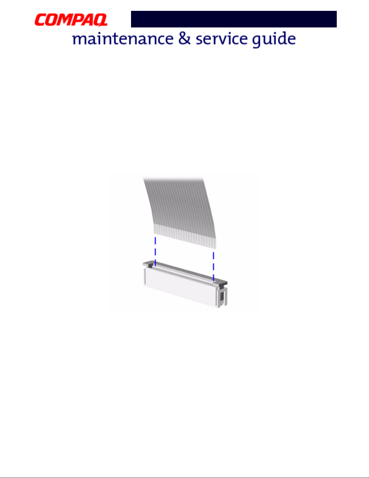
ZIF Connector
The 1200XL Series Notebooks use zero insertion force (ZIF) connectors on the system board.
CAUTION:
Ä
Ä
ÄÄ
only the connector slide when removing or replacing a cable. Never pull or twist on
the cable while it is connected.
To remove a cable from a ZIF connector, lift both corners of the ZIF connector and slide the cable out
simultaneously with constant light force.
A ZIF connector and its attached cable can be easily damaged. Handle
CAUTION:
Ä
Ä
ÄÄ
proper location during the reassembly process. Improper cable placement can
damage the Notebook.
P
RESARIO NOTEBOOK MAINTENANCE AND SERVICE GUIDE
When servicing this Notebook, ensure that cables are placed in their
1200 S
ERIES
R
EMOVAL SEQUENCE
3
Page 5

Presario 1200 Series
Model XL2, XL201, XL202, XL203, XL204, XL205, XL212, XL220, XL222, XL223,
XL3, XL301, XL302, XL303, XL304, XL305, XL307, XL310, XL311,
XL312, XL314, XL320, XL323, XL325, XL326, XL327, XL330
Cables
Most cables used throughout the unit are ribbon cables.
Cables must be handled with extreme care to avoid damage. Use the following precautions when
handling cables to avoid damage to the cable and Notebook:
•
Always handle cables by their connectors.
•
In all cases, avoid bending, twisting, pulling, or tearing cables.
•
Apply only the minimum force required to seat or unseat cables from their connectors.
•
Place the cables in such a manner that they cannot be caught or snagged by parts being
removed or replaced.
•
Handle flex cables with extreme care; they can tear easily.
CAUTION:
Ä
Ä
ÄÄ
proper location during the reassembly process. Improper cable placement can
cause severe damage to the unit.
The following illustrations show the proper placement for each cable:
•
Diskette Drive Ribbon Cable
•
Speaker Assembly Cable
When servicing these Notebooks, ensure that cables are placed in their
•
Keyboard Ribbon Cable
•
Hard Drive Ribbon Cable
4 R
EMOVAL SEQUENCE
P
RESARIO NOTEBOOK MAINTENANCE AND SERVICE GUIDE
1200 S
ERIES
Page 6
Presario 1200 Series
Model XL2, XL201, XL202, XL203, XL204, XL205, XL212, XL220, XL222, XL223,
XL3, XL301, XL302, XL303, XL304, XL305, XL307, XL310, XL311,
XL312, XL314, XL320, XL323, XL325, XL326, XL327, XL330
Diskette Drive Ribbon Cable
The ribbon cable position for the diskette drive is shown below.
CAUTION:
Ä
Ä
ÄÄ
proper location during the reassembly process. Improper cable placement can
damage the Notebook.
P
RESARIO NOTEBOOK MAINTENANCE AND SERVICE GUIDE
When servicing this Notebook, ensure that cables are placed in their
1200 S
ERIES
R
EMOVAL SEQUENCE
5
Page 7
Presario 1200 Series
Model XL2, XL201, XL202, XL203, XL204, XL205, XL212, XL220, XL222, XL223,
XL3, XL301, XL302, XL303, XL304, XL305, XL307, XL310, XL311,
XL312, XL314, XL320, XL323, XL325, XL326, XL327, XL330
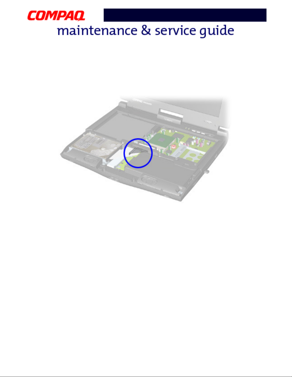
Speaker Assembly Cable
The cable position for the speaker assembly is shown below. The cable is routed under the battery
charger board and under the edge of the system board.
Ä
Ä
ÄÄ
6 R
EMOVAL SEQUENCE
CAUTION:
proper location during the reassembly process. Improper cable placement can
damage the Notebook.
When servicing this Notebook, ensure that cables are placed in their
P
RESARIO NOTEBOOK MAINTENANCE AND SERVICE GUIDE
1200 S
ERIES
Page 8
Presario 1200 Series
Model XL2, XL201, XL202, XL203, XL204, XL205, XL212, XL220, XL222, XL223,
XL3, XL301, XL302, XL303, XL304, XL305, XL307, XL310, XL311,
XL312, XL314, XL320, XL323, XL325, XL326, XL327, XL330
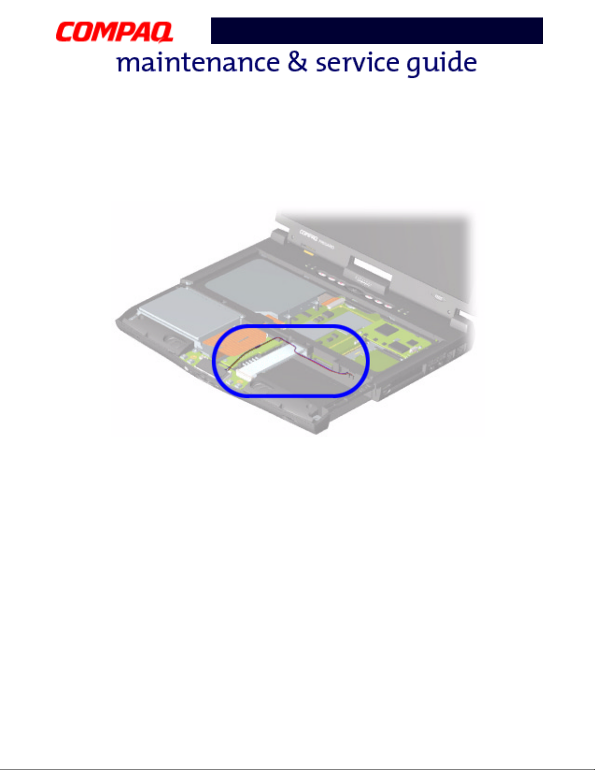
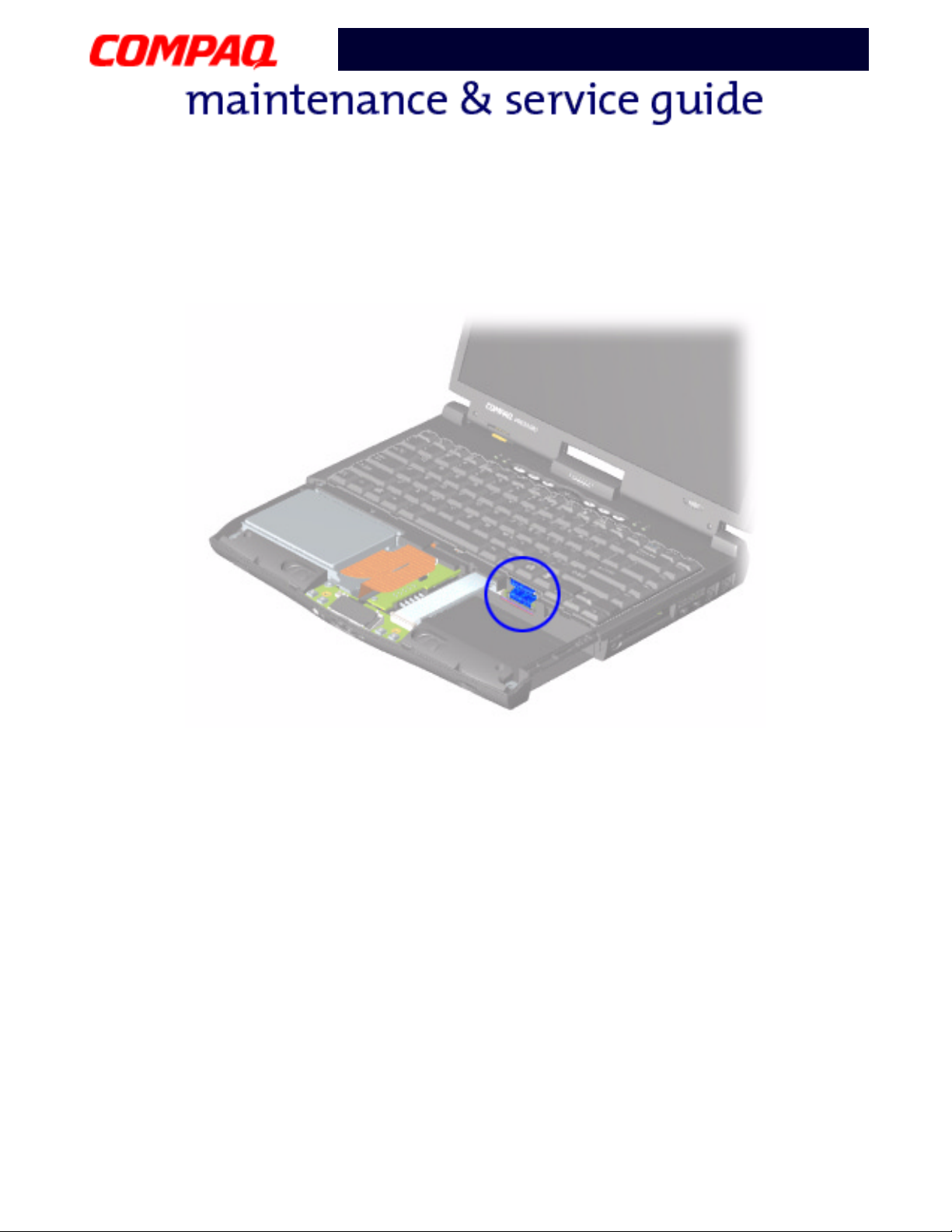
Keyboard Ribbon Cable
The ribbon cable position for the keyboard is shown below.
CAUTION:
Ä
Ä
ÄÄ
proper location during the reassembly process. Improper cable placement can
damage the Notebook.
P
RESARIO NOTEBOOK MAINTENANCE AND SERVICE GUIDE
When servicing this Notebook, ensure that cables are placed in their
1200 S
ERIES
R
EMOVAL SEQUENCE
7
Page 9
Presario 1200 Series
Model XL2, XL201, XL202, XL203, XL204, XL205, XL212, XL220, XL222, XL223,
XL3, XL301, XL302, XL303, XL304, XL305, XL307, XL310, XL311,
XL312, XL314, XL320, XL323, XL325, XL326, XL327, XL330
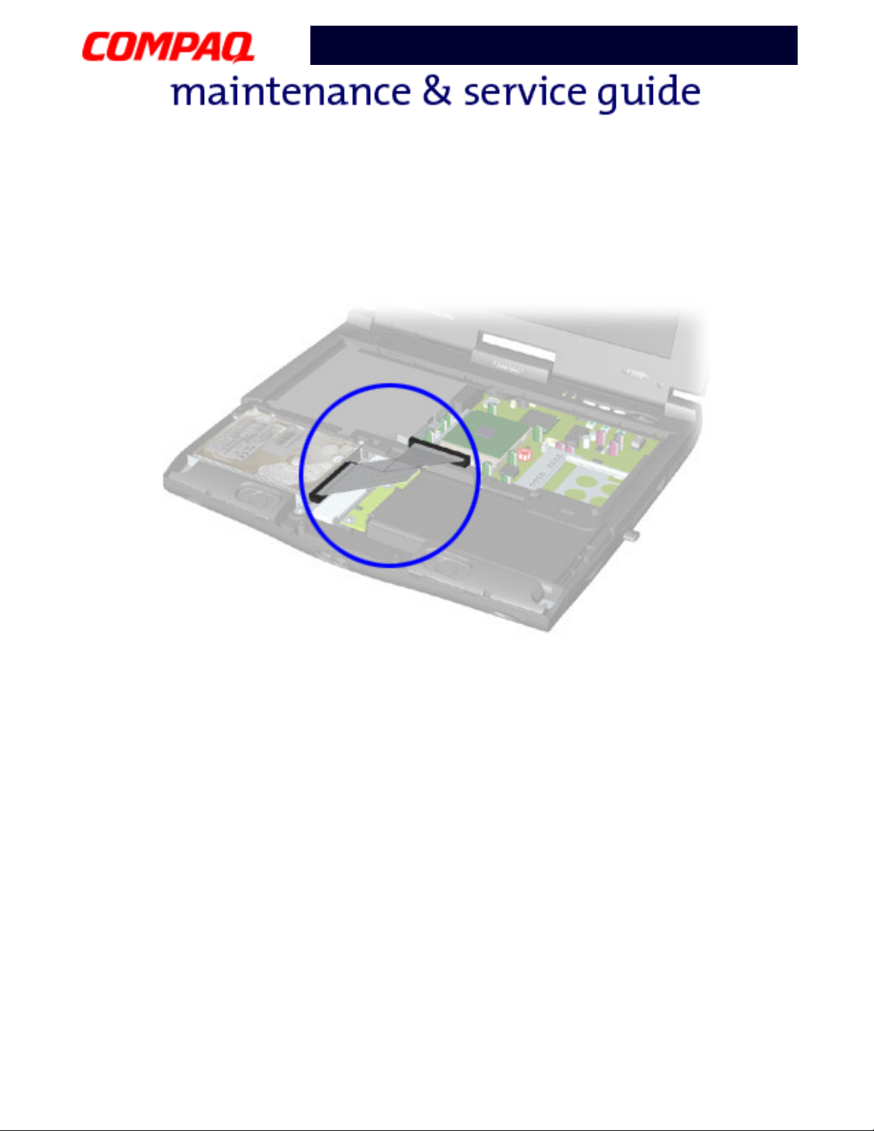
Hard Drive Ribbon Cable
The ribbon cable position for the hard drive is shown below.
Ä
Ä
ÄÄ
8 R
EMOVAL SEQUENCE
CAUTION:
proper location during the reassembly process. Improper cable placement can
damage the Notebook.
When servicing the Notebook, ensure that cables are placed in their
P
RESARIO NOTEBOOK MAINTENANCE AND SERVICE GUIDE
1200 S
ERIES
Page 10

Presario 1200 Series
Model XL2, XL201, XL202, XL203, XL204, XL205, XL212, XL220, XL222, XL223,
XL3, XL301, XL302, XL303, XL304, XL305, XL307, XL310, XL311,
XL312, XL314, XL320, XL323, XL325, XL326, XL327, XL330
Preparing for Disassembly
Before beginning the removal or replacement of any Notebook components, complete the
following steps:
1. Disconnect AC power and any external devices.
2. Remove the battery pack (pg 10
3. Remove any PC Cards.
Important: The battery pack should be removed before performing any internal
maintenance on the Notebook.
WARNING: The Battery Pack contains harmful components when exposed. Do not
Å
open, crush, puncture, or incinerate the battery pack. It contains no
field-serviceable parts. Dispose of battery packs properly. Failure to dispose of
battery packs correctly may cause harm to humans, animals, and
the environment.
CAUTION:
Ä
Ä
ÄÄ
contacts in the battery compartment. To prevent damage, do not allow metal
objects to touch the battery contacts. Place only the battery pack for the Compaq
Presario 1200XL Series Portable Notebooks into the battery compartment. Do not
force the battery pack into the bay if insertion does not occur easily. Do not open
a battery pack; opening causes damage to the pack, making it unuseable.
Note: Compaq Presario 1200XL Series Portable Notebooks have several screws of
various sizes that are not interchangeable. Care must be taken during reassembly
to ensure that the correct screws are used in their correct location. During removal
keep respective screws with their associated subassembly.
Metal objects can damage the battery pack as well as the battery
).
Important: As each component is removed from the Notebook, place the screws
and its associates away from the work area to prevent damage.
P
RESARIO NOTEBOOK MAINTENANCE AND SERVICE GUIDE
1200 S
ERIES
R
EMOVAL SEQUENCE
9
Page 11
Presario 1200 Series
Model XL2, XL201, XL202, XL203, XL204, XL205, XL212, XL220, XL222, XL223,
XL3, XL301, XL302, XL303, XL304, XL305, XL307, XL310, XL311,
XL312, XL314, XL320, XL323, XL325, XL326, XL327, XL330
Removal Procedures
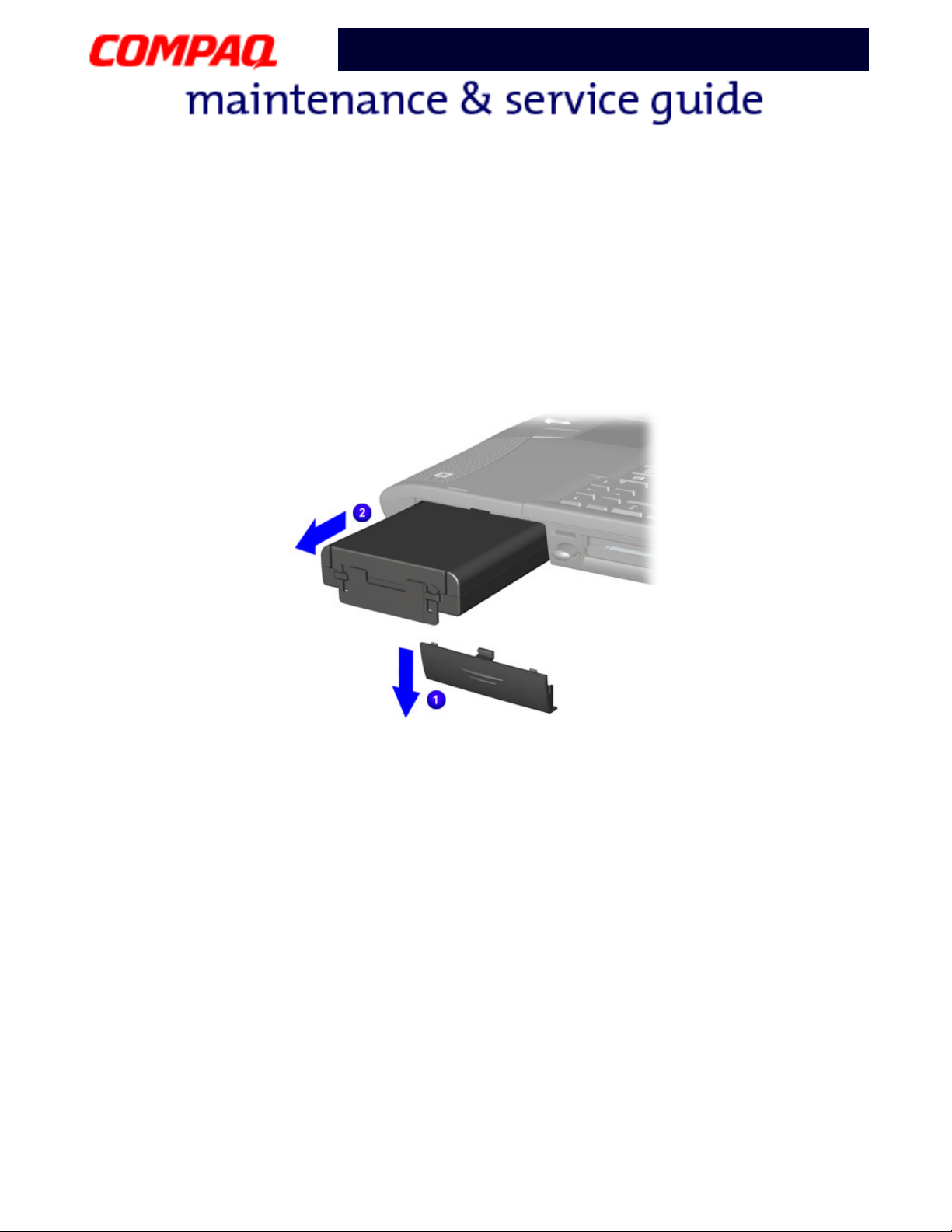
Battery Pack
To remove the battery pack, complete the following steps:
1. Slide
2. Pull
To replace the battery, reverse these procedures.
1 the battery compartment door down and remove it from the chassis.
2 the battery from the chassis by the tab located on the end of the battery pack.
Important: The battery pack should be removed before performing any internal
maintenance on the Notebook.
Å
Ä
Ä
ÄÄ
10 R
EMOVAL SEQUENCE
WARNING: Metal objects can damage the battery pack as well as the battery
contacts in the battery compartment. To prevent damage, do not allow metal
objects to touch the battery contacts. Place only the battery pack for Compaq
Presario 1200XL Series Portable Notebooks into the battery compartment. Do not
force the battery pack into the bay if insertion does not occur easily.
CAUTION: Do not crush, puncture, or incinerate the battery pack. Do not open a
battery pack; this action damages the pack, makes it unusable, and exposes
potentially harmful battery components. No field-serviceable parts are located
inside the battery pack.
P
RESARIO NOTEBOOK MAINTENANCE AND SERVICE GUIDE
1200 S
ERIES
Page 12
Presario 1200 Series
Model XL2, XL201, XL202, XL203, XL204, XL205, XL212, XL220, XL222, XL223,
XL3, XL301, XL302, XL303, XL304, XL305, XL307, XL310, XL311,
XL312, XL314, XL320, XL323, XL325, XL326, XL327, XL330
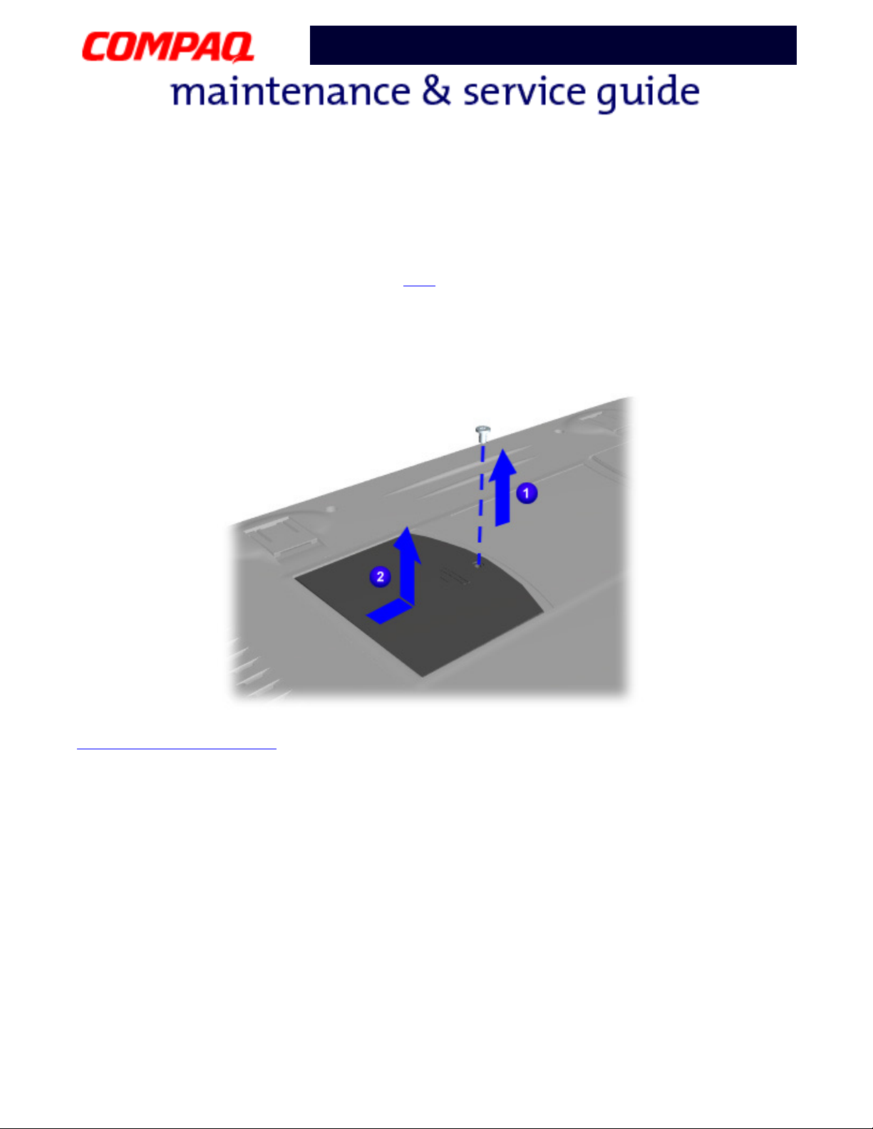
Modem
To remove the modem, complete the following steps:
1. Prepare the Notebook for disassembly (pg 9
).
2. Close the display, turn Notebook upside down and locate the modem compartment (left side
when the front of the Notebook is toward you).
3. Remove one screw
1 from the modem door, 2 slide the door forward and then lift to remove
it.
Continued on the next page
P
RESARIO NOTEBOOK MAINTENANCE AND SERVICE GUIDE
1200 S
ERIES
R
EMOVAL SEQUENCE
11
Page 13
Presario 1200 Series
Model XL2, XL201, XL202, XL203, XL204, XL205, XL212, XL220, XL222, XL223,
XL3, XL301, XL302, XL303, XL304, XL305, XL307, XL310, XL311,
XL312, XL314, XL320, XL323, XL325, XL326, XL327, XL330
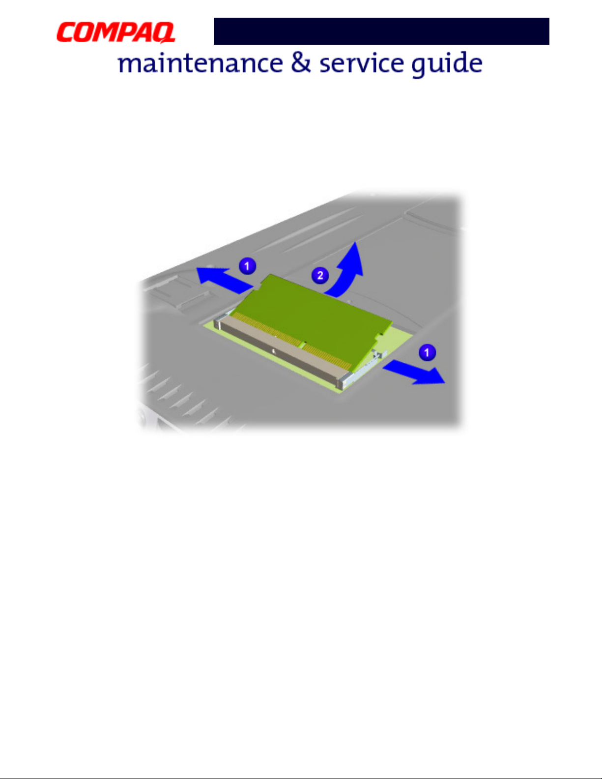
4. Pull 1 the two side latches to release the modem and 2 lift the modem from the system
board connector.
To replace the modem board, reverse these procedures.
12 R
EMOVAL SEQUENCE
P
RESARIO NOTEBOOK MAINTENANCE AND SERVICE GUIDE
1200 S
ERIES
Page 14
Presario 1200 Series
Model XL2, XL201, XL202, XL203, XL204, XL205, XL212, XL220, XL222, XL223,
XL3, XL301, XL302, XL303, XL304, XL305, XL307, XL310, XL311,
XL312, XL314, XL320, XL323, XL325, XL326, XL327, XL330
Memory Module
To remove the memory module, complete the following steps:
1. Prepare the Notebook for disassembly (pg 9
).
2. Close the display and turn the Notebook upside down.
3. Remove the screw from the memory compartment.
4. With the front of the Notebook facing you, slide the door to the left and lift.
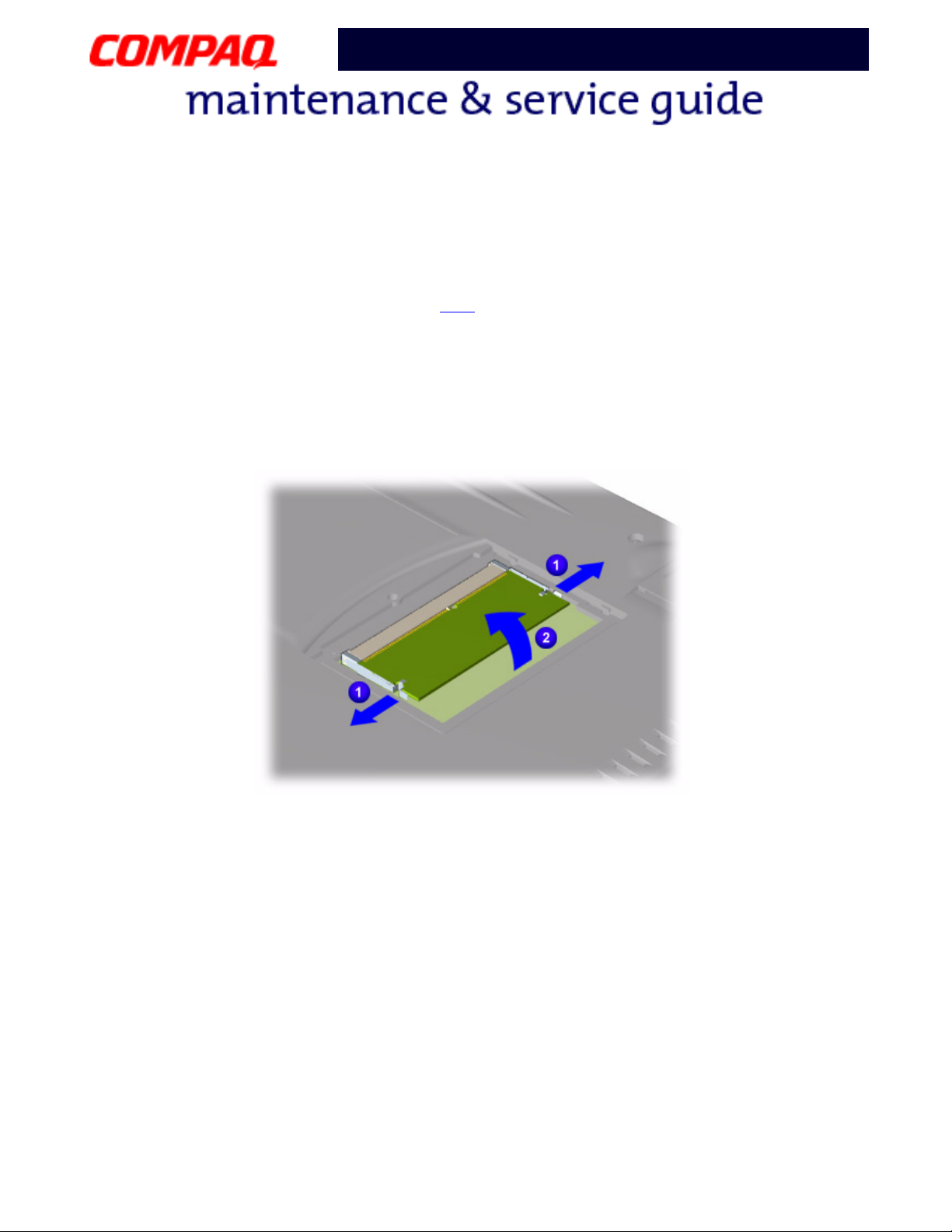
5. Pull
1 the side levers to release the memory module and lift 2 it off the connector on the
system board.
To replace the memory module, reverse these procedures.
P
RESARIO NOTEBOOK MAINTENANCE AND SERVICE GUIDE
1200 S
ERIES
R
EMOVAL SEQUENCE
13
Page 15

Presario 1200 Series
Model XL2, XL201, XL202, XL203, XL204, XL205, XL212, XL220, XL222, XL223,
XL3, XL301, XL302, XL303, XL304, XL305, XL307, XL310, XL311,
XL312, XL314, XL320, XL323, XL325, XL326, XL327, XL330
Palmrest Cover with TouchPad
Note: Compaq Presario 1200XL Series Portable Notebooks have several screws of
various sizes that are not interchangeable. Care must be taken during reassembly
to ensure that the correct screws are used in their correct location. During removal
keep respective screws with their associated subassembly.
Note: components of the Notebook.
To remove the Palmrest cover with TouchPad, complete the following steps:
1. Prepare the Notebook for disassembly (pg 9
).
2. Close the display and turn the Notebook upside down.
3. Remove five screws from underneath the Notebook.
Continued on next page
14 R
EMOVAL SEQUENCE
P
RESARIO NOTEBOOK MAINTENANCE AND SERVICE GUIDE
1200 S
ERIES
Page 16

Presario 1200 Series
Model XL2, XL201, XL202, XL203, XL204, XL205, XL212, XL220, XL222, XL223,
XL3, XL301, XL302, XL303, XL304, XL305, XL307, XL310, XL311,
XL312, XL314, XL320, XL323, XL325, XL326, XL327, XL330
4. Turn the Notebook right side up.
5. Pull the display release latches and open the display assembly.
6. Lift up
1 the front end of the Palmrest cover, 2 disconnect the flex cable from the underside
of the Palmrest LED and Volume Control board.
7. Lift the cover off the unit.
To replace the Palmrest cover with TouchPad, reverse these procedures.
P
RESARIO NOTEBOOK MAINTENANCE AND SERVICE GUIDE
1200 S
ERIES
R
EMOVAL SEQUENCE
15
Page 17

Presario 1200 Series
Model XL2, XL201, XL202, XL203, XL204, XL205, XL212, XL220, XL222, XL223,
XL3, XL301, XL302, XL303, XL304, XL305, XL307, XL310, XL311,
XL312, XL314, XL320, XL323, XL325, XL326, XL327, XL330
Keyboard
To remove the keyboard, complete the following steps:
1. Prepare the Notebook for disassembly (pg 9
2. Remove the Palmrest cover with TouchPad (pg 14
).
).
3. Gently lift up the front of the keyboard, slide it forward, and then turn the keyboard over
allowing it to rest where the Palmrest cover normally sits.
4. Disconnect the flex cable from the ZIF Connector
on the system board and remove the
keyboard.
To replace the keyboard, reverse these procedures.
When replacing the keyboard, the Keyboard Ribbon Cable
rather than underneath the keyboard.
16 R
EMOVAL SEQUENCE
P
RESARIO NOTEBOOK MAINTENANCE AND SERVICE GUIDE
should fold behind the ZIF Connector
1200 S
ERIES
Page 18

Presario 1200 Series
Model XL2, XL201, XL202, XL203, XL204, XL205, XL212, XL220, XL222, XL223,
XL3, XL301, XL302, XL303, XL304, XL305, XL307, XL310, XL311,
XL312, XL314, XL320, XL323, XL325, XL326, XL327, XL330
Heatspreader
To remove the Heatspreader, complete the following steps:
1. Prepare the Notebook for disassembly (pg 9
2. Remove the Palmrest cover with TouchPad (pg 14
3. Remove the keyboard (pg 16
).
).
).
4. Remove four screws from the Heatspreader and lift out of the chassis.
To replace the Heatspreader, reverse these procedures.
Note: If the thermal pads on the Heatspreader are missing or damaged, a new
Heatspreader should be installed.
Important: Before installing the new Heatspreader, remove the plastic covering
from the thermal pads.
To prevent damage, do not use excessive force when replacing the screws.
Å
P
RESARIO NOTEBOOK MAINTENANCE AND SERVICE GUIDE
1200 S
ERIES
R
EMOVAL SEQUENCE
17
Page 19

Presario 1200 Series
Model XL2, XL201, XL202, XL203, XL204, XL205, XL212, XL220, XL222, XL223,
XL3, XL301, XL302, XL303, XL304, XL305, XL307, XL310, XL311,
XL312, XL314, XL320, XL323, XL325, XL326, XL327, XL330
Internet Zone Cover
(Status Panel Assembly)
Note: Illustrations may show parts removed that are not part of this procedure. It is
necessary to remove only the parts listed in the written procedure.
To remove the Internet Zone cover, complete the following steps:
1. Prepare the Notebook for disassembly (pg 9
2. Remove the Palmrest Cover with TouchPad (pg 14
3. Remove the Keyboard (pg 16
).
).
).
4. Open the display, squeeze the sides of the display hinge covers and slide them off the hinges.
Continued on next page
18 R
EMOVAL SEQUENCE
P
RESARIO NOTEBOOK MAINTENANCE AND SERVICE GUIDE
1200 S
ERIES
Page 20

Presario 1200 Series
Model XL2, XL201, XL202, XL203, XL204, XL205, XL212, XL220, XL222, XL223,
XL3, XL301, XL302, XL303, XL304, XL305, XL307, XL310, XL311,
XL312, XL314, XL320, XL323, XL325, XL326, XL327, XL330
5. Close the Display, turn the unit upside down, and then remove two screws that secure the
Internet Zone cover to the chassis located in the back of the Notebook.
Continued on next page
P
RESARIO NOTEBOOK MAINTENANCE AND SERVICE GUIDE
1200 S
ERIES
R
EMOVAL SEQUENCE
19
Page 21

Presario 1200 Series
Model XL2, XL201, XL202, XL203, XL204, XL205, XL212, XL220, XL222, XL223,
XL3, XL301, XL302, XL303, XL304, XL305, XL307, XL310, XL311,
XL312, XL314, XL320, XL323, XL325, XL326, XL327, XL330
6. Remove the two innermost screws from the display hinges that secure the status panel to the
chassis.
Continued on next page
20 R
EMOVAL SEQUENCE
P
RESARIO NOTEBOOK MAINTENANCE AND SERVICE GUIDE
1200 S
ERIES
Page 22

Presario 1200 Series
Model XL2, XL201, XL202, XL203, XL204, XL205, XL212, XL220, XL222, XL223,
XL3, XL301, XL302, XL303, XL304, XL305, XL307, XL310, XL311,
XL312, XL314, XL320, XL323, XL325, XL326, XL327, XL330
7. Turn the unit right side up and open the display.
8. Lift
1 up one corner of the Internet Zone cover and push forward from the back (center piece)
to release the snaps on the Internet Zone cover.
9. Remove
2 Internet Zone cover from the chassis.
To replace the status panel assembly, reverse these procedures.
P
RESARIO NOTEBOOK MAINTENANCE AND SERVICE GUIDE
1200 S
ERIES
R
EMOVAL SEQUENCE
21
Page 23

Presario 1200 Series
Model XL2, XL201, XL202, XL203, XL204, XL205, XL212, XL220, XL222, XL223,
XL3, XL301, XL302, XL303, XL304, XL305, XL307, XL310, XL311,
XL312, XL314, XL320, XL323, XL325, XL326, XL327, XL330
LVDS Board
(Available only on models with a TFT display panel)
Note: Illustrations may show parts removed that are not part of this procedure. It is
necessary to remove only the parts listed in the written procedure.
To remove the internet button board, complete the following steps:
1. Prepare the Notebook for disassembly (pg 9
2. Remove the Internet Zone cover (pg 18
).
3. Carefully disconnect the display flex cable
).
1.
Continued on the next page
22 R
EMOVAL SEQUENCE
P
RESARIO NOTEBOOK MAINTENANCE AND SERVICE GUIDE
1200 S
ERIES
Page 24

Presario 1200 Series
Model XL2, XL201, XL202, XL203, XL204, XL205, XL212, XL220, XL222, XL223,
XL3, XL301, XL302, XL303, XL304, XL305, XL307, XL310, XL311,
XL312, XL314, XL320, XL323, XL325, XL326, XL327, XL330
4. Remove one screw securing the LVDS button board and remove it from the chassis.
To replace the LVDS button board, reverse these procedures.
P
RESARIO NOTEBOOK MAINTENANCE AND SERVICE GUIDE
1200 S
ERIES
R
EMOVAL SEQUENCE
23
Page 25

Presario 1200 Series
Model XL2, XL201, XL202, XL203, XL204, XL205, XL212, XL220, XL222, XL223,
XL3, XL301, XL302, XL303, XL304, XL305, XL307, XL310, XL311,
XL312, XL314, XL320, XL323, XL325, XL326, XL327, XL330
Hard Drive
Note: Illustrations may show parts removed that are not part of this procedure. It is
necessary to remove only the parts listed in the written procedure.
To remove the hard drive, complete the following steps:
1. Prepare the unit for disassembly (pg 9
2. Remove the Palmrest cover with TouchPad (pg 14
).
).
3. Remove the four screws from the hard drive mounting bracket.
4. Disconnect the hard drive ribbon cable.
5. Lift out the hard drive with mounting brackets attached.
Continued on next page
24 R
EMOVAL SEQUENCE
P
RESARIO NOTEBOOK MAINTENANCE AND SERVICE GUIDE
1200 S
ERIES
Page 26

Presario 1200 Series
Model XL2, XL201, XL202, XL203, XL204, XL205, XL212, XL220, XL222, XL223,
XL3, XL301, XL302, XL303, XL304, XL305, XL307, XL310, XL311,
XL312, XL314, XL320, XL323, XL325, XL326, XL327, XL330
Hard Drive Mounting Brackets
To remove the hard drive mounting brackets, remove two screws from each side of the hard drive.
To replace the hard drive and mounting brackets, reverse these procedures.
P
RESARIO NOTEBOOK MAINTENANCE AND SERVICE GUIDE
1200 S
ERIES
R
EMOVAL SEQUENCE
25
Page 27

Presario 1200 Series
Model XL2, XL201, XL202, XL203, XL204, XL205, XL212, XL220, XL222, XL223,
XL3, XL301, XL302, XL303, XL304, XL305, XL307, XL310, XL311,
XL312, XL314, XL320, XL323, XL325, XL326, XL327, XL330
Processor
To remove the processor, complete the following steps:
1. Prepare the Notebook for disassembly (pg 9
2. Remove the Palmrest cover with TouchPad (pg 14
3. Remove the keyboard (pg 16
4. Remove the Heatspreader (pg 17
).
).
).
).
5. Lift the lever to release the processor, and lift the processor off the system board connector.
Continued on next page
26 R
EMOVAL SEQUENCE
P
RESARIO NOTEBOOK MAINTENANCE AND SERVICE GUIDE
1200 S
ERIES
Page 28

Presario 1200 Series
Model XL2, XL201, XL202, XL203, XL204, XL205, XL212, XL220, XL222, XL223,
XL3, XL301, XL302, XL303, XL304, XL305, XL307, XL310, XL311,
XL312, XL314, XL320, XL323, XL325, XL326, XL327, XL330
Processor (Replacing)
To replace the processor, perform the following:
1. Fully align the processor pins with the system board connector.
Note: When replacing the processor, verify that the number one pin (the gold triangle) is
properly aligned with the number one pin on the system board connector.
2. Press down carefully on the processor directly over the connectors to seat the processor on the
system board.
3. Lower the lever to lock the processor in place.
4. Reassemble the remaining components by reversing their removal procedures.
P
RESARIO NOTEBOOK MAINTENANCE AND SERVICE GUIDE
1200 S
ERIES
R
EMOVAL SEQUENCE
27
Page 29

Presario 1200 Series
Model XL2, XL201, XL202, XL203, XL204, XL205, XL212, XL220, XL222, XL223,
XL3, XL301, XL302, XL303, XL304, XL305, XL307, XL310, XL311,
XL312, XL314, XL320, XL323, XL325, XL326, XL327, XL330
CD/DVD Drive
To remove the CD/DVD Drive, complete the following steps:
1. Prepare the Notebook for disassembly (pg 9
2. Remove the Palmrest cover with TouchPad (pg 14
3. Remove the keyboard (pg 16
4. Remove the Heatspreader (pg 17
).
).
).
).
5. Turn the Notebook upside down and remove the two screws securing the CD/DVD drive to the
chassis.
6. Turn the Notebook over (right side up) and push the CD/DVD drive forward from the back of
the drive to slide it out of the chassis.
To replace the CD/DVD drive, reverse these procedures.
28 R
EMOVAL SEQUENCE
P
RESARIO NOTEBOOK MAINTENANCE AND SERVICE GUIDE
1200 S
ERIES
Page 30

Presario 1200 Series
Model XL2, XL201, XL202, XL203, XL204, XL205, XL212, XL220, XL222, XL223,
XL3, XL301, XL302, XL303, XL304, XL305, XL307, XL310, XL311,
XL312, XL314, XL320, XL323, XL325, XL326, XL327, XL330
Display Panel Assembly
Note: Illustrations may show parts removed that are not part of this procedure. It is
necessary to remove only the parts listed in the written procedure.
1. To remove the display panel assembly, complete the following steps:
2. Prepare the Notebook for disassembly (pg 9
3. Remove the Internet zone cover (pg 18
4. Disconnect the display flex cable
1 and backlight cable 2 from the system board.
).
).
Continued on the next page
P
RESARIO NOTEBOOK MAINTENANCE AND SERVICE GUIDE
1200 S
ERIES
R
EMOVAL SEQUENCE
29
Page 31

Presario 1200 Series
Model XL2, XL201, XL202, XL203, XL204, XL205, XL212, XL220, XL222, XL223,
XL3, XL301, XL302, XL303, XL304, XL305, XL307, XL310, XL311,
XL312, XL314, XL320, XL323, XL325, XL326, XL327, XL330
5. While supporting the display, remove 1 the two outermost screws securing the display to the
chassis and lift
2 the display panel out of the hinges.
To replace the display panel, reverse these procedures.
30 R
EMOVAL SEQUENCE
P
RESARIO NOTEBOOK MAINTENANCE AND SERVICE GUIDE
1200 S
ERIES
Page 32

Presario 1200 Series
Model XL2, XL201, XL202, XL203, XL204, XL205, XL212, XL220, XL222, XL223,
XL3, XL301, XL302, XL303, XL304, XL305, XL307, XL310, XL311,
XL312, XL314, XL320, XL323, XL325, XL326, XL327, XL330
Upper CPU Cover
To remove the upper CPU cover, complete the following:
1. Prepare the Notebook for disassembly (pg 9
2. Remove the Palmrest cover with TouchPad (pg 14
3. Remove the keyboard (pg 16
4. Remove the Heatspreader (pg 17
).
).
5. Remove the Internet zone cover (pg 18
6. Remove the LVDS button board (pg 22
7. Remove the hard drive (pg 24
).
8. Remove the display panel assembly (pg 29
).
).
).
).
).
9. Remove four screws located on the top of the upper CPU cover and lift the cover off the
chassis.
P
RESARIO NOTEBOOK MAINTENANCE AND SERVICE GUIDE
1200 S
ERIES
R
EMOVAL SEQUENCE
31
Page 33

Presario 1200 Series
Model XL2, XL201, XL202, XL203, XL204, XL205, XL212, XL220, XL222, XL223,
XL3, XL301, XL302, XL303, XL304, XL305, XL307, XL310, XL311,
XL312, XL314, XL320, XL323, XL325, XL326, XL327, XL330
Fan Assembly
To remove the fan assembly, complete the following:
1. Prepare the Notebook for disassembly (pg 9
).
2. Remove the Palmrest cover with TouchPad (pg 14
3. Remove the keyboard (pg 16
4. Remove the Heatspreader (pg 17
5. Remove the Internet zone cover (pg 18
6. Remove the LVDS button board (pg 22
7. Remove the hard drive (pg 24
8. Remove the display panel assembly (pg 29
9. Remove the upper CPU cover (pg 31
10. Disconnect
1 the fan cable from the connector on the system board and lift 2 the fan
).
).
).
).
).
).
).
assembly from the chassis slot.
).
Continued on the next page
32 R
EMOVAL SEQUENCE
P
RESARIO NOTEBOOK MAINTENANCE AND SERVICE GUIDE
1200 S
ERIES
Page 34

Presario 1200 Series
Model XL2, XL201, XL202, XL203, XL204, XL205, XL212, XL220, XL222, XL223,
XL3, XL301, XL302, XL303, XL304, XL305, XL307, XL310, XL311,
XL312, XL314, XL320, XL323, XL325, XL326, XL327, XL330
Fan Gasket
To remove the fan gasket, pull the gasket from the fan.
To replace the fan assembly and gasket, reverse these procedures.
Important: When replacing the fan assembly ensure the manufacturing label is pointing
inward.
P
RESARIO NOTEBOOK MAINTENANCE AND SERVICE GUIDE
1200 S
ERIES
R
EMOVAL SEQUENCE
33
Page 35

Model XL2, XL201, XL202, XL203, XL204, XL205, XL212, XL220, XL222, XL223,
XL3, XL301, XL302, XL303, XL304, XL305, XL307, XL310, XL311,
XL312, XL314, XL320, XL323, XL325, XL326, XL327, XL330
Real Time Clock Battery
Presario 1200 Series
CAUTION:
Ä
Ä
ÄÄ
all setup attributes that are programmed in the CMOS.
To remove the RTC battery, complete the following steps:
1. Prepare the Notebook for disassembly (pg 9
2. Remove the Palmrest cover with TouchPad (pg 14
3. Remove the keyboard (pg 16
4. Remove the Heatspreader (pg 17
5. Remove the Upper CPU Cover (pg 31
6. Locate the RTC battery next to the CD/DVD connector.
7. Using a non-metallic object, gently pry upward to remove the RTC battery.
To replace the RTC battery, press the battery firmly into the socket and reassemble the remaining
components by reversing their removal procedures.
Removing the RTC battery clears the power-on password and removes
).
).
).
).
).
34 R
EMOVAL SEQUENCE
P
RESARIO NOTEBOOK MAINTENANCE AND SERVICE GUIDE
1200 S
ERIES
Page 36

Presario 1200 Series
Model XL2, XL201, XL202, XL203, XL204, XL205, XL212, XL220, XL222, XL223,
XL3, XL301, XL302, XL303, XL304, XL305, XL307, XL310, XL311,
XL312, XL314, XL320, XL323, XL325, XL326, XL327, XL330
Battery Charger Board
(Voltage Converter Board)
To remove the battery charger board, complete the following:
1. Prepare the Notebook for disassembly (pg 9
2. Remove the Palmrest cover with TouchPad (pg 14
3. Remove the keyboard (pg 16
4. Remove the Heatspreader (pg 17
).
).
5. Remove the Internet zone cover (pg 18
6. Remove the LVDS button board (pg 22
7. Remove the hard drive (pg 24
).
8. Remove the display panel assembly (pg 29
9. Remove the upper CPU cover (pg 31
).
).
).
).
).
).
10. Remove the hard drive cable located above the battery charger board.
11. Remove the floppy cable located above the battery charger board.
Continued on next page
P
RESARIO NOTEBOOK MAINTENANCE AND SERVICE GUIDE
1200 S
ERIES
R
EMOVAL SEQUENCE
35
Page 37

Presario 1200 Series
Model XL2, XL201, XL202, XL203, XL204, XL205, XL212, XL220, XL222, XL223,
XL3, XL301, XL302, XL303, XL304, XL305, XL307, XL310, XL311,
XL312, XL314, XL320, XL323, XL325, XL326, XL327, XL330
12. Remove 1 two screws from the battery charger board and unplug 2 the board from the
connector on the system board.
13. Lift the battery charger board out of the chassis.
To replace the battery charger board, reverse these procedures.
Important: When replacing the battery charger board, ensure that the pins are aligned
with the connector on the system board.
36 R
EMOVAL SEQUENCE
P
RESARIO NOTEBOOK MAINTENANCE AND SERVICE GUIDE
1200 S
ERIES
Page 38

Presario 1200 Series
Model XL2, XL201, XL202, XL203, XL204, XL205, XL212, XL220, XL222, XL223,
XL3, XL301, XL302, XL303, XL304, XL305, XL307, XL310, XL311,
XL312, XL314, XL320, XL323, XL325, XL326, XL327, XL330
Diskette Drive
To remove the diskette drive, complete the following:
1. Prepare the Notebook for disassembly (pg 9
2. Remove the Palmrest cover with TouchPad (pg 14
3. Remove the keyboard (pg 16
4. Remove the Heatspreader (pg 17
5. Remove the CD or DVD drive (pg 28
6. Remove the Internet Zone cover (pg 18
7. Remove the LVDS button board (pg 22
).
).
).
).
).
8. Remove the display panel assembly (pg 29
9. Remove the hard drive (pg 24
10. Remove the upper CPU cover (pg 31
11. Remove the battery charger board (pg 35
).
).
).
Continued on next page
).
).
).
P
RESARIO NOTEBOOK MAINTENANCE AND SERVICE GUIDE
1200 S
ERIES
R
EMOVAL SEQUENCE
37
Page 39

Presario 1200 Series
Model XL2, XL201, XL202, XL203, XL204, XL205, XL212, XL220, XL222, XL223,
XL3, XL301, XL302, XL303, XL304, XL305, XL307, XL310, XL311,
XL312, XL314, XL320, XL323, XL325, XL326, XL327, XL330
12. Remove 1 screw from the diskette drive retaining bracket and lift 2 the bracket out of the
chassis.
Continued on next page
38 R
EMOVAL SEQUENCE
P
RESARIO NOTEBOOK MAINTENANCE AND SERVICE GUIDE
1200 S
ERIES
Page 40

Presario 1200 Series
Model XL2, XL201, XL202, XL203, XL204, XL205, XL212, XL220, XL222, XL223,
XL3, XL301, XL302, XL303, XL304, XL305, XL307, XL310, XL311,
XL312, XL314, XL320, XL323, XL325, XL326, XL327, XL330
13. Lift the diskette drive from the chassis.
To replace the diskette drive, reverse these procedures.
CAUTION:
Ä
Ä
ÄÄ
reassembly process.
P
RESARIO NOTEBOOK MAINTENANCE AND SERVICE GUIDE
Ensure that cables are placed in their proper locations during the
1200 S
ERIES
R
EMOVAL SEQUENCE
39
Page 41

Presario 1200 Series
Model XL2, XL201, XL202, XL203, XL204, XL205, XL212, XL220, XL222, XL223,
XL3, XL301, XL302, XL303, XL304, XL305, XL307, XL310, XL311,
XL312, XL314, XL320, XL323, XL325, XL326, XL327, XL330
Speaker Assembly
To remove the speaker assembly, complete the following:
1. Prepare the Notebook for disassembly (pg 9
2. Remove the Palmrest cover with TouchPad (pg 14
3. Remove the keyboard (pg 16
).
4. Remove the display panel assembly (pg 29
5. Remove the Internet zone cover (pg 18
6. Remove the LVDS button board (pg 22
7. Remove the Heatspreader (pg 17
).
8. Remove the upper CPU cover (pg 31
9. Remove the hard drive (pg 24
).
10. Remove the battery charger board (pg 35
).
).
).
).
Continued on next page
).
).
).
40 R
EMOVAL SEQUENCE
P
RESARIO NOTEBOOK MAINTENANCE AND SERVICE GUIDE
1200 S
ERIES
Page 42

Presario 1200 Series
Model XL2, XL201, XL202, XL203, XL204, XL205, XL212, XL220, XL222, XL223,
XL3, XL301, XL302, XL303, XL304, XL305, XL307, XL310, XL311,
XL312, XL314, XL320, XL323, XL325, XL326, XL327, XL330
11. Disconnect 1 the speaker cables from the system board and lift 2 the speaker assembly from
the chassis.
Note: Before disconnecting the speaker cables from the system board, verify the color
coded positioning of the left and right speaker cables to ensure that the Speaker
Assembly Cable is placed in its proper location during the reassembly process.
To replace the speaker assembly, reverse these procedures.
P
RESARIO NOTEBOOK MAINTENANCE AND SERVICE GUIDE
1200 S
ERIES
R
EMOVAL SEQUENCE
41
Page 43

Presario 1200 Series
Model XL2, XL201, XL202, XL203, XL204, XL205, XL212, XL220, XL222, XL223,
XL3, XL301, XL302, XL303, XL304, XL305, XL307, XL310, XL311,
XL312, XL314, XL320, XL323, XL325, XL326, XL327, XL330
System Board
To remove the system board, complete the following steps:
1. Prepare the Notebook for disassembly (pg 9
2. Remove the Palmrest cover with TouchPad (pg 14
3. Remove the keyboard (pg 16
).
4. Remove the display panel assembly (pg 29
5. Remove the Internet zone cover (pg 18
6. Remove the LVDS button board (pg 22
7. Remove the Heatspreader (pg 17
8. Remove the processor (pg 26
9. Remove the CD or DVD drive (pg 28
10. Remove the upper CPU cover (pg 31
11. Remove the hard drive (pg 24
12. Remove the fan assembly (pg 32
).
).
).
).
).
).
13. Remove the battery charger board (pg 35
).
).
).
).
).
).
14. Disconnect the diskette drive ribbon cable from the system board (pg 5
15. Disconnect the speaker assembly cables from the system board (pg 40
).
).
Continued on next page
42 R
EMOVAL SEQUENCE
P
RESARIO NOTEBOOK MAINTENANCE AND SERVICE GUIDE
1200 S
ERIES
Page 44

Presario 1200 Series
Model XL2, XL201, XL202, XL203, XL204, XL205, XL212, XL220, XL222, XL223,
XL3, XL301, XL302, XL303, XL304, XL305, XL307, XL310, XL311,
XL312, XL314, XL320, XL323, XL325, XL326, XL327, XL330
16. Remove the two standoffs from the system board.
17. Remove the two screws from the CD/DVD drive mounting rail and lift the mounting rail from
the system board.
Continued on next page
P
RESARIO NOTEBOOK MAINTENANCE AND SERVICE GUIDE
1200 S
ERIES
R
EMOVAL SEQUENCE
43
Page 45

Presario 1200 Series
Model XL2, XL201, XL202, XL203, XL204, XL205, XL212, XL220, XL222, XL223,
XL3, XL301, XL302, XL303, XL304, XL305, XL307, XL310, XL311,
XL312, XL314, XL320, XL323, XL325, XL326, XL327, XL330
18. Remove three screws from the system board.
Note: Ensure that the PCMCIA eject button is not sticking out through the slot in the
chassis.
19. Shift the board to the left and lift to remove it from the chassis.
To replace the system board, reverse these procedures.
Before replacing the system board, remove all remaining cables.
44 R
EMOVAL SEQUENCE
P
RESARIO NOTEBOOK MAINTENANCE AND SERVICE GUIDE
1200 S
ERIES
 Loading...