

Page 1

THIS IS A REPRINT, INCLUDING CHANGES 1 AND 2
*TB 9-6625-082-50
DEPARTMENT OF THE ARMY TECHNICAL BULLETIN
CALIBRATION PROCEDURE FOR
OSCILLOSCOPE, HEWLETT-PACKARD
MODELS 120A, 120AR, 120B. AND 120BR
Headquarters, Department of the Army, Washington, DC
14 January 1974
♦♦REPORTING OF ERRORS♦♦
You can help improve this publication by calling attention to errors and by
recommending improvements and stating your reasons for the recommendations.
Your letter or DA Form 2028, Recommended Changes to Publications, should be
mailed directly to Commander, U.S. Army Aviation and Missile Command,
ATTN: AMSAM-TMD-EP, Redstone Arsenal, AL 35898-5000. FAX to DSN 7882313 (commercial 256-842-2313). A reply will be furnished directly to you.
SECTION I. IDENTIFICATION AND DESCRIPTION
Test instrument identification .............................. 1 2
Calibration data card, DA Form 2416 .................. 2 2
Calibration description......................................... 3 3
II. EQUIPMENT REQUIREMENTS
Equipment required.............................................. 4 4
Accessories required ............................................. 5 5
III. PRELIMINARY OPERATIONS
Preliminary instructions....................................... 6 5
Equipment Setup.................................................. 7 6
IV. CALIBRATION PROCESS FOR MODELS
120A AND 120 AR
Intensity limit.................................................... 8 6
Vertical and horizontal amplifier dc balance..... 9 7
Triggering range and level................................. 10 9
Vertical and horizontal sensitivity and range ... 11 12
Calibrator........................................................... 12 13
Vertical amplifier frequency response and
attenuator compensation ................................... 13 13
Horizontal amplifier frequency response and
attenuator compensation ................................... 14 14
Amplifier phase shift.......................................... 15 16
Paragraph Page
__________
This bulletin supersedes TB 9-6625-082-50, 17 September 1970.
Page 2

TB 9-6625-082-50
V. CALIBRATION PROCESS FOR MODELS
Paragraph Page
Sweep timing...................................................... 16 16
Sweep magnifier................................................. 17 17
Power supply ...................................................... 18 18
Final procedure.................................................. 19 18
120B AND 120BR
Equipment setup................................................ 20 19
Intensity limit.................................................... 21 19
Vertical amplifier dc balance............................. 22 20
Triggering range and level................................. 23 21
Vertical and horizontal sensitivity and range ... 24 23
Calibrator........................................................... 25 24
Vertical amplifier frequency response and
attenuator compensation ................................... 26 24
Horizontal amplifier frequency response and
attenuator compensation ................................... 27 27
Amplifier phase shift.......................................... 28 28
Sweep timing...................................................... 29 28
Sweep magnifier................................................. 30 29
Power supply ...................................................... 31 30
Final procedure.................................................. 32 30
SECTION I
IDENTIFICATION AND DESCRIPTION
1. Test Instrument Identification. This bulletin provides instructions for the
calibration of Oscilloscope, Hewlett-Packard Models 120A, 120AR, 120B, and 120BR. The
manufacturer’s instruction manuals were used as the prime data source in compiling these
instructions. The oscilloscope will be referred to as the "TI" (test instrument) throughout
this bulletin.
a. Model Variations. Variations among models are described in text.
b. Time and Technique. The time required for this calibration is approximately 4
hours using the dc and low frequency technique.
2. Calibration Data Card, DA Form 2416
a. Forms, records, and reports required for calibration personnel at all levels are
prescribed by TM 38-750. DA Form 2416 must be annotated in accordance with TM 38-750
for each calibration performed.
b. Adjustments to be reported on DA Form 2416 are designated (R) at the end of the
sentence in which they appear. When adjustments are in tables, the (R) will follow the
designated adjustment. Report only those adjustments made and designated with (R).
2
Page 3

TB 9-6625-082-50
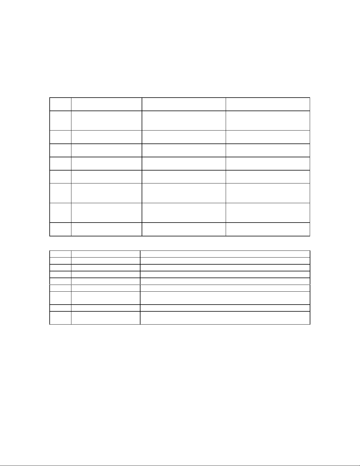
3. Calibration Description. TI parameters and performance specifications which
pertain to this calibration are listed in table 1.
Table 1. Calibration Description
Test instrument parameters Performance specifications
Power input requirements
Vertical and horizontal amplifier bandwidth
(models 120 and 120AR):
Dc coupled
Ac coupled
Vertical amplifier bandwidth (models 120B and
120BR):
Dc coupled
Ac coupled
Horizontal amplifier bandwidth (models 120B and
120BR):
Dc coupled
Ac coupled
Horizontal sensitivity:
Range
Vernier
Accuracy
Vertical sensitivity:
Range
Vernier
Accuracy (models 120A and 120AR)
Accuracy (models 120B and 120BR)
Internal calibrator Calibrator signal automatically connected to
Common-mode rejection
Phase shift Vertical and horizontal amplifiers have same
See footnote at end of table.
1
1
115 or 230 vac ±10%, 50 to 1000 Hz, 130 w
Dc to 200 kHz
2 Hz to 200 kHz
Dc to 450 kHz
2 Hz to 450 kHz
Dc to 300 kHz
2 Hz to 300 kHz
0.1 to 100 v/cm in 3 calibrated steps; .1, 1, and 10
v/cm
Continuously variable between steps and extends
10 v/cm step to at least 100 v/cm
±5%
10 mv/cm to 100 v/cm in 4 calibrated steps; 10 mv,
100 mv, 1 v, and 10 v/cm
Continuously variable between steps and extends
10 v/cm step to at least 100 v/cm
±5%
±3%
vertical amplifier; accuracy ±2%
At least 40 db. Common mode signal must not
exceed ±3 v peak
phase characteristics within ±2° to 100 kHz
when verniers are in CAL
3
Page 4

TB 9-6625-082-50
Table 1. Cable Description - Continued.
Test Instrument Parameters Performance Specifications
Sweep:
Sweep range
Vernier
Accuracy
Sweep expand
Automatic triggering (models 120A and 120AR):
Internal
External
Trigger point
Automatic triggering (models 120B and 120BR):
Internal
External
Trigger point
Selectable trigger level:
Models 120A and 120AR
Models 120B and 120BR
1
This specification is for information only and is not necessarily verified in this bulletin.
1
1 µsec to 0.5 sec/cm in 15 calibrated steps 1, 2, 5,
10, etc., sequence, 5 µsec/cm to 200 ms/cm
Continuously variable between ranges and
extends 200 ms/cm step to at least 0.5 sec/cm
±5%
X5 sweep expansion may be used on all ranges
and extends fastest sweep to 1 µsec/cm,
accuracy ±10%
From signals 50 Hz to 250 kHz causing 0.5 cm or
more vertical deflection; and from line voltage
At least 2.5 v p-p
Zero crossing, negative slope of external sync
signals; zero crossing, positive or negative slope
of vertical deflection signal
From signals 50 Hz to 450 kHz causing 0.5 cm or
more vertical deflection; and from line voltage
At least 1.5 v p-p
Zero crossing, negative slope of external sync
signals; zero crossing, positive or negative slope
of vertical signal
Screwdriver control overrides automatic
triggering and permits trigger point to be set
between -10 to +10 v
Front-panel control overrides automatic triggering
and permits trigger point to be set between -7 to
+7 v
SECTION II
EQUIPMENT REQUIREMENTS
4. Equipment Required. Table 2 identifies the specific equipment used in this
calibration procedure. This equipment is issued with secondary transfer calibration
standards set 4931-621-7877 and is to be used in performing this procedure. Alternate
items may be used by the calibrating activity when the equipment listed in table 2 is not
available. The items selected must be verified to perform satisfactorily prior to use and
must bear evidence of current calibration. The equipment must meet or exceed the
minimum use specifications listed in table 2. The accuracies listed in table 2 provide a fourto-one accuracy ratio between the standard and TI. Where the four-to-one ratio cannot be
met, the actual accuracy of the equipment selected is shown in parenthesis.
4
Page 5
TB 9-6625-082-50
5. Accessories Required. The accessories listed in table 3 are issued with secondary
transfer calibration standards set 4931-621-7877 and are to be used in this calibration
procedure. When necessary, these items may be substituted by equivalent items unless
specifically prohibited.
Table 2. Minimum Specifications of Equipment Required
Minimum use
Item Common name
A1 AC/DC VOLTMETER Range:-146 to -154 V dc;
Accuracy: ±..75%
A2 AUTOTRANSFORMER Range:105 to 125 V ac
Accuracy: ±1%
A3 DC VOLTMETER Range:-1235 to -2363 V
Accuracy: ±1.66%
A4 SIGNAL GENERATOR Frequency: 100 kHz
Voltage: 0.03 to 20 V rms
A5 SQUARE-WAVE
GENERATOR
A6 VOLTAGE
CALIBRATOR
A7 TEST OSCILLATOR Frequency: 10 Hz to 500 kHz
A8 TIME-MARK
GENERATOR
Frequency: 5 to 30 kHz
Voltage: 0.8 to 50 V p-p
Range:34.5825 mv rms to 37.2
Accuracy: ±..75%
Voltage: 0.03 to 2.9 v rms
Accuracy: ±.75%
Range:1 µsec to 50 ms
Accuracy: ±..75%
specifications
+33.58 to +37.12 V ac
v rms
Manufacturer and model
(part number)
Dana, Model 5703-S-2127
(7912606)
General Radio, Model
W10MT3AS3 (7910809)
Electrical Instruments Service,
Model ESV (MIS-10276)
Hewlett-Packard, Model 202CR
(8616395-2)
Tektronix, Type 106 (MIS-
10284)
Hewlett-Packard, Model 745A
(MIS-10342)
Preston, Model 134A (MIS-
10224)
Tektronix, Type 184MOD146B
(7912042-2)
Table 3. Accessories Required
Item Common Name Description and Part Number
B1 ADAPTER
B2 ADAPTER BNC jack to double banana plug (7907592)
B3 ADAPTER BNC T type, 2 jacks, 1 plug (MS35173-274)
B4 CABLE 30-in., RG-58/U; BNC plug terminations (7907467)
B5 CABLE
B6 CABLE
B7 LEAD 24-in., No. 18 AWG; single banana plug terminations (7907498)
B8 TERMINATION 50-ohm feed-through; BNC jack to BNC plug Hewlett-Packard,
1
Two required.
1
1
1
Single banana jack to alligator clip (black) (7907560)
30-in., RG-58/U; double banana plug terminations (7907470)
36-in., RG-58/U; BNC plug and double banana plug terminations
(7907471)
Model 11048B (11048B)
SECTION III
PRELIMINARY OPERATIONS
6. Preliminary Instructions
a. The instructions outlined in this section are preparatory to the calibration process.
Personnel should become familiar with the entire bulletin before beginning the calibration.
5
Page 6

TB 9-6625-082-50
b. Items of equipment used in this procedure are referenced within the text by common
name and item identification number as listed in tables 2 and 3. For the identification of
equipment referenced by item numbers prefixed with A, see table 2, and for prefix B, see
table 3.
WARNING
HIGH VOLTAGE is used during the performance of this
calibration. DEATH ON CONTACT may result if personnel
fail to observe safety precautions.
7. Equipment Setup
a. Remove protective cover from TI.
b. Connect TI to autotransformer (A2).
c. Connect autotransformer to 115-volt ac source and adjust for 115 volts ac.
CAUTION
To prevent damage to crt, turn INTENSITY control fully
counterclockwise during warm-up.
d. Energize equipment and allow sufficient time for equipment to warm up and
stabilize.
SECTION IV
CALIBRATION PROCESS FOR MODELS 120A AND 120AR
NOTE
Unless otherwise specified, verify the results of each test and
take corrective action whenever the test requirement is not met
before continuing with the procedure.
NOTE
When indications specified in paragraphs 8 through 17 are not
within tolerance, perform the power supply check prior to
making adjustments. After adjustments are made, repeat
paragraphs 8 through 17. Do not perform power supply check
if all other parameters are within tolerance.
8. Intensity Limit
a. Performance Check
(1) Position TI controls as listed in (a) through (i) below:
6
Page 7

(a) TRIGGER LEVEL control to AUTO.
(b) INTENSITY control fully counterclockwise.
(c) Vertical AC-DC switch to AC.
(d) VERT. SENSITIVITY VERNIER control to CAL.
(e) VERT. SENSITIVITY switch to 1 VOLTS/CM.
(f) SWEEP EXPAND switch to X1.
(g) SWEEP TIME-HOR. SENS. switch to 1 MILLISECONDS/CM.
(h) SYNC switch to INT + (positive).
(i) HORIZ. POS. and VERT. POS. controls to midrange.
(2) Adjust INTENSITY and FOCUS controls for normal display. If normal display
cannot be obtained, perform b below.
b. Adjustments
(1) Position TI controls as listed in (a) through (c) below:
TB 9-6625-082-50
(a) SWEEP TIME-HOR. SENS. switch to 10 VOLTS/CM.
(b) FOCUS control for best focus.
(c) INTENSITY control index marker to 9 o'clock position.
(2) Adjust R316 (fig. 1) for a small round spot.
(3) Adjust R322 (fig. 1) until spot just disappears.
9. Vertical and Horizontal Amplifier Dc Balance
a. Performance Check
(1) Position TI controls as listed in (a) through (e) below:
(a) VERT SENSITIVITY switch to 10 VOLTS/CM.
(b) VERT SENSITIVITY VERNIER control fully counterclockwise.
(c) VERT POS. control to center spot on graticule.
(d) Vertical AC-DC switch to DC.
(e) SWEEP TIME-HOR SENS. switch to 10 VOLTS/CM.
7
Page 8
TB 9-6625-082-50
(2) Vary VERT. SENSITIVITY VERNIER control. If spot does not remain in center
of graticule, perform b(1) through (3) below.
(3) Turn VERT SENSITIVITY VERNIER control to CAL. VERT SENSITIVITY to
OFF, and SWEEP TIME HOR. SENS. switch to 10 V/CM.
(4) Repeat (1) and (2) above, using horizontal controls. If spot does not remain in
center of graticule, perform b(4) through (8) below.
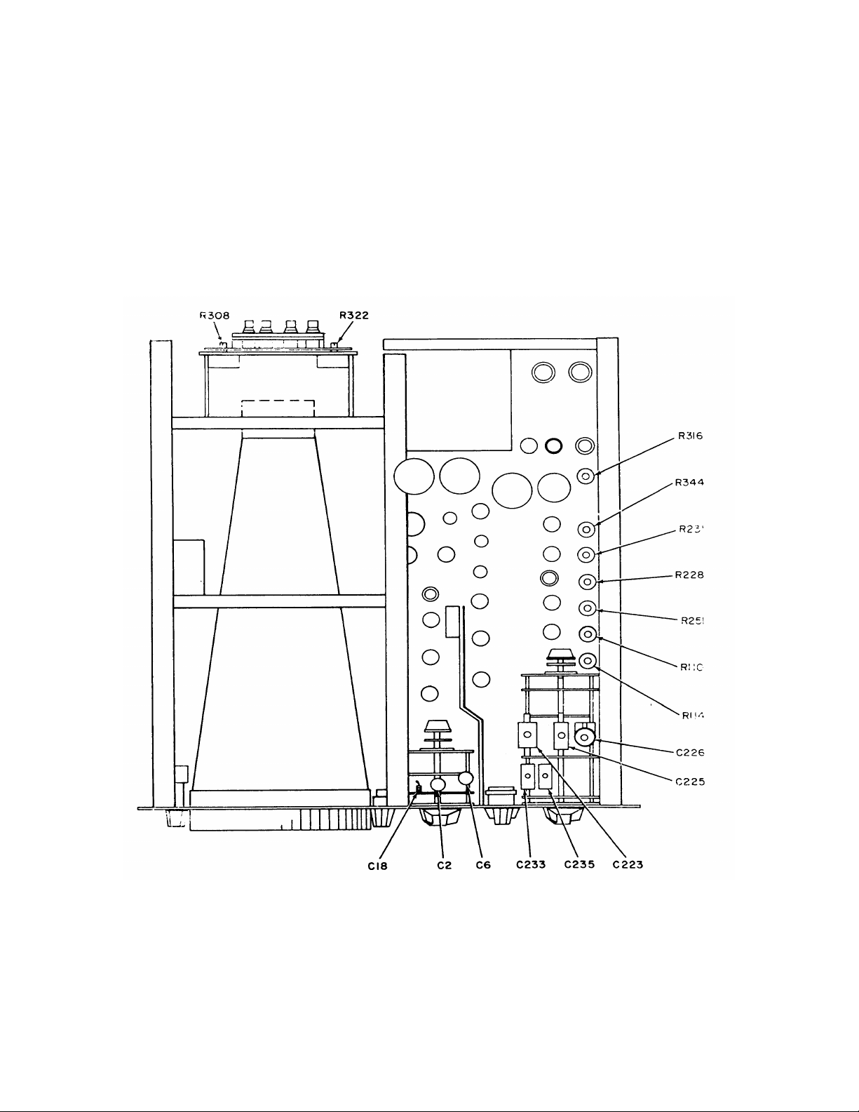
Figure 1. Oscilloscope - top view.
8
Page 9

b. Adjustments
(1) Turn VERT SENSITIVITY VERNIER control to midrange.
(2) Adjust VERT. DC BAL. control (front panel) to center spot on graticule.
(3) Vary VERT. SENSITIVITY VERNIER control and adjust VERT. DC BAL.
control until no spot shift is observed.
(4) Turn SWEEP TIME-HOR. SENS. VERNIER control fully counterclockwise.
(5) Adjust R110 (fig. 1) to center spot on graticule.
(6) Turn SWEEP TIME-HOR. SENS. VERNIER control to CAL.
(7) Turn HORIZ. POS. control to center spot on graticule.
(8) Repeat (4) through (7) above until no shift is observed when varying SWEEP
TIME HOR. SENS. VERNIER control.
10. Triggering Range and Level
TB 9-6625-082-50
a. Performance Check
(1) Position TI controls as listed in (a) through (c) below:
(a) VERT SENSITIVITY switch to 1 VOLTS/CM.
(b) SWEEP TIME-HOR. SENS. switch to 5 MICROSECONDS/CM.
(c) SYNC switch to EXT.
(2) Observe that baseline is displayed on TI crt.
(3) Connect test oscillator (A7) to TI horizontal input connector, using cable and
termination (B6 and B8).
(4) Connect TI horizontal input connector to TI vertical input connector, using cable
(B5).
(5) Adjust test oscillator frequency to 250 kHz and amplitude for stable display on
TI.
(6) Slowly reduce test oscillator amplitude until TI display becomes unstable. If
test oscillator amplitude is not .70 volt rms or less, perform b(1) and (2) below.
(7) Turn SWEEP TIME-HOR. SENS. switch to 10 MILLISECONDS/CM.
9
Page 10

TB 9-6625-082-50
(8) Adjust test oscillator frequency to 50 Hz and amplitude for display on TI.
(9) Repeat (6) above.
NOTE
Some adjustment of TI TRIGGER LEVEL control may be
necessary at high frequencies.
(10) Turn SYNC switch to INT + (positive) and SWEEP TIME-HOR. SENS. switch to
50 MICROSECONDS/CM.
(11) Adjust test oscillator to 10 kHz and .8 centimeters of display on TI crt. If sweep
does not trigger on positive-going portion of display waveform, perform b(3) through (11)
below.
(12) Turn SYNC switch to INT-(negative). Observe that sweep triggers on negative
going part of waveform.
b. Adjustments
(1) Adjust test oscillator amplitude for stable display on TI.
(2) Adjust R247 (fig. 2) while reducing test oscillator amplitude until triggering
becomes stable at minimum test oscillator amplitude (less than .70 volt rms).
(3) Turn TI VERT. SENSITIVITY VERNIER control to CAL.
(4) Connect ac/dc voltmeter (A1) between pin 8 of V203 (fig. 2) and chassis ground.
(5) If no trace is present on TI, perform adjustments (a) and (b) below:
(a) Adjust R228 (fig. 1) counterclockwise until trace appears.
(b) Turn R228 clockwise until trace just disappears.
(6) If trace is present, adjust R228 clockwise until trace just disappears.
(7) Record ac/dc voltmeter indication.
(8) Connect lead (B7) with two adapters (B1), between pin 1 of V201 (fig. 2) and
chassis ground.
(9) Slowly turn R228 counterclockwise until trace appears and then clockwise until
trace just disappears. Record ac/dc voltmeter indication.
above.
10
(10) Adjust R228 for indication of 2 volts more positive than value recorded in (9)
Page 11
(11) Remove lead connected in (8) above.
TB 9-6625-082-50
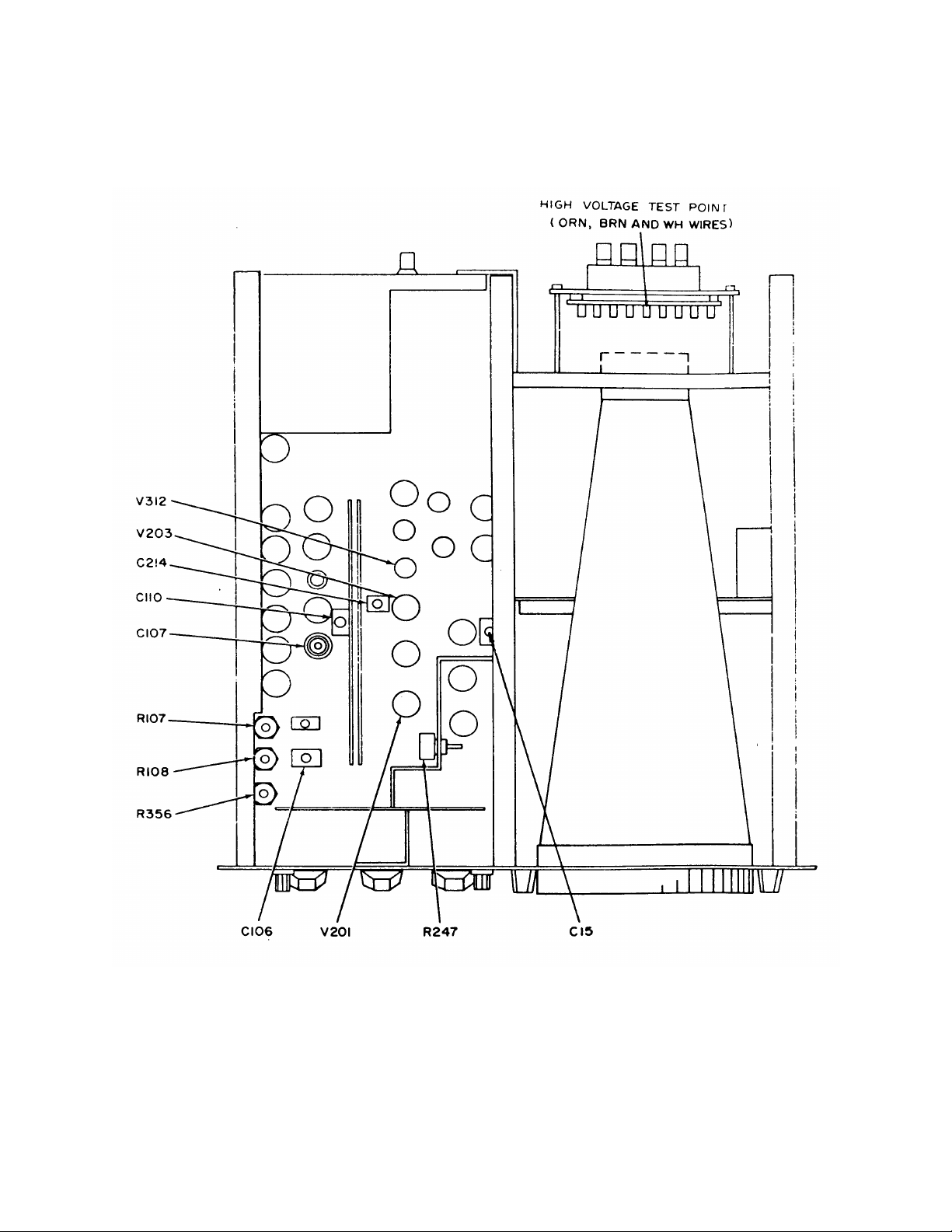
Figure 2. Oscilloscope - bottom view.
11
Page 12

TB 9-6625-082-50
11. Vertical and Horizontal Sensitivity and Range
a. Performance Check
(1) Position TI controls as listed in (a) through (d) below:
(a) SYNC switch to INT + (positive).
(b) SWEEP TIME-HOR. SENS. switch to 1 MILLISECOND/CM.
(c) VERT. SENSITIVITY switch to 100 MILLIVOLTS/CM.
(d) VERT. AC-DC switch to AC.
(2) Connect voltage calibrator (A6) to TI vertical input connector, using cable (B5).
Connect negative and ground vertical input connector together with ground strap.
(3) Adjust voltage calibrator for a 10-centimeter display amplitude on TI crt. If
voltage calibrator does not indicate between 335.825 and 371.175 millivolts rms, perform
b(1) and (2) below.
(4) Repeat (3) above, using settings listed in table 4. If voltage calibrator does not
indicate within limits specified, perform b(1) and (2) below to obtain best in-tolerance
compromise for all VERT. SENSITIVITY switch positions.
Table 4. Vertical and Horizontal Sensitivity and Range
Test instrument Voltage calibrator
VERT. SENSITIVITY indication (rms)
switch settings Min Max
10 mV/cm 33.5825 mV 37.1175 mV
1 V/cm 3.358 V 3.712 V
10 V/cm 33.58 V 37.12 V
(5) Connect voltage calibrator (A6) to horizontal input connectors of TI.
(6) Turn HORIZONTAL AC-DC switch to AC and SWEEP TIME-HOR. SENS.
switch to .1 VOLTS/CM.
(7) Adjust voltage calibrator for a 10-centimeter horizontal deflection on TI crt. If
voltage calibrator does not indicate between 335.825 and 371.175 millivolts rms, perform
b(3) and (4) below.
(8) Repeat technique of (6) above, 1 VOLT/CM and 10 VOLTS/CM settings listed in
table 4, and substituting HOR. SENS. switch for VERT SENSITIVITY switch. If voltage
calibrator does not indicate within specified limits, perform b(3) and (4) below to obtain best
in-tolerance compromise of error.
12
Page 13

TB 9-6625-082-50
b. Adjustments
(1) Adjust voltage calibrator for a .3535-volt rms output.
(2) Adjust VERT. GAIN control for 10 centimeters of display amplitude on TI crt.
(3) Adjust voltage calibrator output to .3535 volt rms.
(4) Adjust R114 (fig. 1) for 10 centimeters of horizontal display amplitude on TI crt.
(R)
12. Calibrator
a. Performance Check. Turn VERT. SENSITIVITY switch to CAL 6 CM and
SWEEP TIME-HOR. SENS. switch to 2 MILLISECONDS/CM. If display amplitude does
not indicate 6 centimeters, perform b below.
b. Adjustments. Adjust R356 (fig. 2) for display amplitude of 6 centimeters on crt.(R)
13. Vertical Amplifier Frequency Response and Attenuator Compensation
a. Performance Check
(1) Turn VERT. SENSITIVITY switch to 10 MILLIVOLTS/CM and SWEEP TIMEHOR. SENS. switch to 100 MILLISECONDS/CM.
(2) Connect test oscillator (A7) to TI vertical input connectors; using cable and
termination (B6 and B8).
(3) Adjust test oscillator for 10 Hz and for a display amplitude of 10 centimeters.
Note indication of test oscillator output meter.
(4) Maintain constant test oscillator output amplitude noted in (3) above, and
Increase test oscillator frequency until display amplitude is 8 centimeters. Test oscillator
frequency will be at least 200 kHz.
(5) Disconnect test oscillator and connect output of square-wave generator (A5) to
TI vertical input terminals, using cable and termination supplied with square-wave
generator, and adapter (B2).
(6) Turn SWEEP TIME-HOR. SENS. switch to 5 MICROSECONDS/CM.
(7) Adjust square-wave generator to 50 kHz and 8 centimeters of display amplitude
on TI crt. If square wave with maximum of 2 percent overshoot is not displayed; perform
b(1) below.
(8) Turn SWEEP TIME-HOR. SENS. switch to 200 MICROSECONDS/CM and
VERT. SENSITIVITY switch to 100 MILLIVOLTS.
13
Page 14

TB 9-6625-082-50
(9) Adjust square-wave generator to 5 kHz and 8 centimeters of amplitude display.
If flat-top square wave is not displayed, perform b(2) below.
(10) Turn VERT. SENSITIVITY switch to 1 VOLTS/CM and adjust square-wave
generator for 8 centimeters of display. If flat-top is not displayed, perform b(3) below.
b. Adjustments
(1) Adjust C15 (fig. 2) for best square-wave response.
(2) Adjust C6 (fig. 1) for flat-top square wave.
(3) Adjust C2 (fig. 1) for flat-top square wave.
14. Horizontal Amplifier Frequency Response and Attenuator Compensation
a. Performance Check
(1) Position TI controls as listed in (a) through (c) below:
(a) SWEEP TIME-HOR. SENS. switch to .1 VOLTS/CM.
(b) Horizontal AC-DC switch to DC.
(c) VERT. POS. control to center display.
(2) Connect test oscillator (A7) to TI horizontal input connectors, using cable and
termination (B6 and B8).
(3) Adjust test oscillator to 10 Hz and a 10-centimeter trace length. Note indication
of test oscillator level meter.
(4) Maintain constant test oscillator output amplitude of (3) above, and increase test
oscillator frequency until trace length is 8 centimeters. Test oscillator frequency will be at
least 200 kHz.
(5) Connect equipment as shown in figure 3.
(6) Adjust square-wave generator (A5) to 50 kHz and 8 centimeters of display
amplitude.
(7) Adjust test oscillator for approximately 5 kHz and stable display of 10
centimeters. Readjust test oscillator frequency for best display of square wave. If square
wave with flat top and maximum of 2 percent overshoot is not displayed; perform b(1)
below.
14
Page 15

TB 9-6625-082-50
Figure 3. Horizontal amplifier compensation - equipment setup.
(8) Turn SWEEP TIME-HOR. SENS. switch to 1 VOLTS/CM.
(9) Adjust square-wave generator to 5 kHz and 8 centimeters of display. Adjust test
oscillator to approximately 500 Hz and stable display of 8 centimeters. If flat-top square
wave is not displayed, perform b(2) below.
(10) Turn SWEEP TIME-HOR. SENS. switch to 10 VOLTS/CM. If flat-top square
wave is not displayed, perform b(3) below.
b. Adjustments
(1) Adjust C110 (fig. 2) for best square wave response. (R)
(2) Adjust C235 (fig. 1) for flat-top square wave. (R)
(3) Adjust C233 (fig. 1) for flat-top square wave. (R)
15
Page 16

TB 9-6625-082-50
15. Amplifier Phase Shift
a. Performance Check
(1) Position TI controls as listed in (a) through (c) below:
(a) SWEEP TIME-HOR. SENS. switch to .1 VOLTS/CM.
(b) VERT SENSITIVITY switch to 100 MILLIVOLTS/CM.
(c) Horizontal AC-DC switch to AC.
(2) Connect signal generator (A4) to TI vertical input connectors, using cable (B5).
(3) Connect TI vertical input connectors to horizontal input connectors, using cable
(B5).
(4) Adjust signal generator to 100 kHz and approximately 6 centimeters deflection
on TI crt. If pattern opening on crt is more than 0.2 centimeter, perform b(1) below.
(5) Turn SWEEP TIME-HOR. SENS. and VERT. SENSITIVITY switches to 10
VOLTS/CM.
(6) Increase signal generator output to obtain approximately same pattern as
before. If pattern opening on crt is more than 0.2 centimeter, perform b(2) below.
b. Adjustments
(1) Adjust C107 (fig. 2) for closed pattern on crt. (R)
(2) Adjust C18 (fig. 1) for closed pattern on crt. (R)
16. Sweep Timing
a. Performance Check
(1) Connect MARKER OUTPUT jack of time-mark generator (A8) to TI vertical
input connectors, using cable (B6).
(2) Turn SWEEP TIME-HOR. SENS. switch to 10 MILLISECONDS/CM and VERT.
SENSITIVITY switch to 1 VOLT.
(3) Set time-mark generator to 5 mS.
(4) Adjust HORIZ. POS. control to align third time marker with second vertical
graticule line. If nineteenth marker is not displayed within ± 0.5 centimeter of tenth
graticule line, and sweep length is not 10.5 centimeters; perform b below.
16
Page 17

TB 9-6625-082-50
(5) Turn SWEEP TIME-HOR. SENS. switch to 5 MICROSECONDS/CM. Adjust
time-mark generator for 5 µS output.
(6) Adjust HORIZ. POS. control to align second marker with second vertical
graticule line. Tenth time marker will be within 0.5 centimeter of tenth vertical graticule
line.
(7) Repeat technique of (5) and (6) above, using values listed in table 5. Perform
adjustments listed in the table as necessary for out-of-tolerance sweep timing.
Table 5. Sweep Timing
Test instrument Time-mark
SWEEP TIME-HOR. generator Time mark/
SENS. switch output cm Adjustments
10 MICROSECONDS/CM
20 MICROSECONDS/CM 10 µs 2 - - -
50 MICROSECONDS/CM 50 µs 1 C225 (fig. 1) (R)
100 MICROSECONDS/CM 0.1 ms 1 - - 200 MICROSECONDS/CM 0.1 ms 2 - - -
.5 MILLISECONDS/CM 0.5 ms 1 C223 (fig. 1) (R)
1 MILLISECONDS/CM 1 ms 1 - - 2 MILLISECONDS/CM 1 ms 2 - - 5 MILLISECONDS/CM 5 ms 1 - - -
20 MILLISECONDS/CM 10 ms 2 - - 50 MILLISECONDS/CM 50 ms 1 R251 (fig. 1) (R)
1
Adjust C226 until last five markers coincide with last five major graticule divisions (one marker per cm). (R)
2
Adjust C214 until first five markers coincide with first five major graticule divisions (one marker per cm). (R)
10 µs
1 C2261 (fig. 1) (R)
C2142 (fig. 2) (R)
b. Adjustments. Adjust R107 (R) (fig. 2) for one marker per centimeter and R231 (R)
(fig. 1) for sweep length of 10.5 centimeters.
17. Sweep Magnifier
a. Performance Check
(1) Turn SWEEP TIME-HOR. SENS. switch to 10 MILLISECONDS/CM and
SWEEP EXPAND switch to X5.
(2) Set time-mark generator (A8) to 10 mS.
NOTE
Adjust TI TRIGGER LEVEL control for stable display, if
necessary.
(3) Adjust HORIZ. POS. control to align first time marker with left-hand graticule
edge. If one marker per 5 centimeters is not displayed, perform b(1) below.
17
Page 18

TB 9-6625-082-50
(4) Turn SWEEP TIME-HOR. SENS. switch to 20 MICROSECONDS/CM.
(5) Set time-mark generator to 1 µS.
(6) Adjust HORIZ. POS. control to align fifth time marker with second vertical
graticule line. If thirty-seventh time marker is not within I centimeter of 10th vertical
graticule line, perform b(2) below.
b. Adjustments
(1) Adjust R108 (fig. 2) for one marker per five centimeters. (R)
(2) Adjust C106 (fig. 2) for equal spacing of markers on first portion of sweep (four
markers per centimeter).(R)
18. Power Supply
NOTE
Do not perform power supply check if all other parameters are
within tolerance.
a. Performance Check
(1) Connect ac/dc voltmeter (A1) between pin 2 of V312 (fig. 2) and chassis ground.
If ac/dc voltmeter does not indicate between -146 and -154 volts dc, perform b(1) below.
Record ac/dc voltmeter indication.
(2) Adjust autotransformer (A2) from 105 to 125 volts and back to 115 volts. Ac/dc
voltmeter will indicate within ±1 percent of indication recorded in (1) above.
(3) Connect positive lead of dc voltmeter (A3) to chassis ground and negative lead to
HIGH VOLTAGE TEST POINT (fig. 2). If dc voltmeter does not indicate between -2137
and -2363 volts, perform b(2) below.
b. Adjustments
(1) Adjust R344 (fig. 1) for indication of -150 volts dc on ac/dc voltmeter. (R)
(2) Adjust R308 (fig. 1) for indication of -2250 volts dc on dc voltmeter. (R)
19. Final Procedure
a. Deenergize and disconnect all equipment and reinstall protective covers on TI.
b. In accordance with TM 38-750, annotate and affix DA Label 80 (U.S. Army
Calibration System). When the TI cannot be adjusted within tolerance, annotate, and affix
DA Form 2417 (Unserviceable or Limited Use tag).
18
Page 19

TB 9-6625-082-50
SECTION V
CALIBRATION PROCESS FOR MODELS 120B AND 120BR
NOTE
Unless otherwise specified, verify the results of each test and
take corrective action whenever the test requirement is not met
before continuing with the procedure.
NOTE
When indications specified in paragraphs 21 through 30 are
not within tolerance, perform the power supply check prior to
making adjustments. After adjustments are made, repeat
paragraphs 21 through 30. Do not perform power supply check
if all other parameters are within tolerance.
20. Equipment Setup
a. Remove protective cover from TI.
b. Connect TI to autotransformer (A2) and connect autotransformer to 115-volt ac
source, and adjust for 115 volts ac.
c. Energize TI by turning INTENSITY and POWER control to ON and allow 20
minutes for equipment to warm up and stabilize.
21. Intensity Limit
a. Performance Check
(1) Position TI controls as listed in (a) through (i) below:
(a) TRIGGER SOURCE switch to INT + (Positive).
(b) TRIGGER SOURCE/LEVEL control to AUTO
(c) INTENSITY control fully counter. clockwise, but not to OFF.
(d) Vertical AC/DC switch to AC.
(e) VERTICAL SENSITIVITY/VERNIER control to CAL.
(f) VERTICAL SENSITIVITY switch to 1 VOLTS/CM.
(g) SWEEP MAGNIFIER switch to X1.
(h) HORIZONTAL DISPLAY switch to 1 MILLISECONDS/CM.
19
Page 20

TB 9-6625-082-50
(i) Horizontal POSITION and vertical POSITION controls to midrange.
To prevent damage to the crt, turn INTENSITY control of TI
back to position of normal viewing brightness immediately
after performing (2) below.
(2) Adjust INTENSITY and FOCUS controls for normal display. If normal display
cannot be obtained, perform b below.
b. Adjustments
(1) Position TI controls as listed in (a) through (c) below:
(a) HORIZONTAL DISPLAY switch to 10 VOLTS/CM.
(b) FOCUS control for best focus.
(c) INTENSITY control index marker to 9 o'clock position.
(2) Adjust R316 (fig. 4) for a small round spot.
CAUTION
(3) Adjust R320 (fig. 4) until spot disappears.
22. Vertical Amplifier Dc Balance
a. Performance Check
(1) Position TI controls as listed in (a) through (e) below:
(a) HORIZONTAL DISPLAY switch to 10 VOLTS/CM.
(b) VERTICAL SENSITIVITY switch to 10 VOLTS/CM.
(c) VERTICAL SENSITIVITY/VERNIER control fully counterclockwise.
(d) VERTICAL POSITION control to center spot on graticule.
(e) Vertical AC-DC switch to DC.
(2) Vary VERTICAL SENSITIVITY/VERNIER control and observe that spot
remains in center of graticule. If spot moves, perform b below.
b. Adjustments
20
(1) Turn VERTICAL SENSITIVITY/VERNIER control fully counterclockwise.
Page 21

TB 9-6625-082-50
Figure 4. Oscilloscope - top view.
(2) Adjust BAL control (front panel) to center spot on TI crt graticule.
(3) Vary VERT. SENSITIVITY VERNIER control and adjust BAL control until no
spot shift is observed.
23. Triggering Range and Level
a. Performance Check
(1) Position TI controls as listed in (a) through (d) below:
(a) VERTICAL SENSITIVITY VERNIER control to CAL.
(b) VERTICAL SENSITIVITY switch to 1 VOLTS/CM.
21
Page 22

TB 9-6625-082-50
(c) HORIZONTAL DISPLAY switch to 5 µSEC/CM.
(d) TRIGGER SOURCE switch to EXT.
(2) Observe that baseline is displayed on TI crt.
(3) Connect test oscillator (A7) to TI horizontal input connector, using cable and
termination (B6 and B8).
(4) Connect TI horizontal input connector to TI vertical input connector, using cable
(B6).
(5) Adjust test oscillator frequency to 450 kHz and output amplitude for a stable
display on TI crt.
(6) Slowly reduce test oscillator amplitude until TI display becomes unstable. If
test oscillator amplitude does not indicate 0.5 volt rms or less, perform b(1) and (2) below.
(7) Turn HORIZONTAL DISPLAY switch to 10 MILLISECONDS/CM.
(8) Adjust test oscillator frequency to 50 Hz and amplitude output for a stable
display on TI crt.
(9) Repeat (6) above.
NOTE
Some adjustment of TI TRIGGER SOURCE/ LEVEL control
may be necessary at high frequency.
(10) Turn TRIGGER SOURCE switch to INT + (positive) and HORIZONTAL
DISPLAY switch to 50 µSEC/CM.
(11) Adjust test oscillator to 10 kHz and an 8-centimeter display on TI crt.
(12) Adjust HORIZONTAL DISPLAY switch for several cycles of display. If sweep
does not trigger on positive-going portion of displayed waveform, perform b(3) through (6)
below.
(13) Turn TI TRIGGER SOURCE switch to INT - (negative). Observe that sweep
triggers on negative-going part of display.
b. Adjustments
(1) Adjust test oscillator amplitude output to 0.53 volt rms.
(2) Adjust R203 (fig. 4) until triggering becomes stable.
22
Page 23

(3) Position TI controls as listed in (a) through (d) below:
(a) VERTICAL SENSITIVITY switch to CAL.
(b) HORIZONTAL DISPLAY switch to .5 MILLISECONDS/CM.
(c) TRIGGER SOURCE switch to INT + (positive).
(d) TRIGGER SOURCE/LEVEL control just out of AUTO.
(4) Connect ac/dc voltmeter (A1) between pin 2 of V202 (fig. 4) and chassis ground.
(5) Adjust R258 (fig. 4) clockwise until sweep free-runs and then counterclockwise
until sweep trace just disappears. Record ac/dc voltmeter indication.
(6) Adjust R258 (fig. 4) for indication of 3 volts more positive than the value
recorded in (5) above.
24. Vertical and Horizontal Sensitivity and Range
a. Performance Check
(1) Position TI controls as listed in (a) through (c) below:
TB 9-6625-082-50
(a) HORIZONTAL DISPLAY switch to 1 MILLISECONDS/CM
(b) VERTICAL AC-DC switch to AC.
(c) VERTICAL SENSITIVITY switch to 100 MILLIVOLTS/CM.
(2) Connect voltage calibrator (A6) to TI vertical input connector, using cable (B5).
Connect negative and ground vertical input connector together using ground strap.
(3) Adjust voltage calibrator for a 10-centimeter amplitude display on TI crt. If
voltage calibrator does not indicate between 335.825 and 371.175 millivolts rms, perform
b(1) and (2) below.
(4) Repeat (3) above, using settings listed in table 6. Voltage calibrator will indicate
within limits specified.
Table 6. Vertical and Horizontal Sensitivity
Test instrument Voltage calibrator or Ac/dc
VERTICAL voltmeter indication (rms)
SENSITIVITY Min Max
switch settings Vert Horiz Vert Horiz
10 MV/CM 33.5825 mv - - - 37.1175 mv - - -
1 VOLTS/CM 3.429 v 3.358 v 3.641 v 3.712 v
10 VOLTS/CM 34.29 v 33.58 v 36.41 v 37.12 v
23
Page 24

TB 9-6625-082-50
(5) Connect voltage calibrator (A6) to horizontal input of TI, using cable (B6).
(6) Turn HORIZONTAL DISPLAY switch to .1 VOLTS/CM.
(7) Adjust voltage calibrator for a 10 centimeter horizontal deflection on crt. If
voltage calibrator does not indicate between 335.825 and 371.175 millivolts rms, perform
b(3) and (4) below.
(8) Repeat technique of (7) above at 1 VOLT/CM and 10 VOLTS/CM settings listed
in table 6 for HORIZONTAL DISPLAY. Indications will be within limits specified.
b. Adjustments
(1) Adjust voltage calibrator for a 353.5 millivolt rms output.
(2) Adjust CAL control for a 10-centimeter display amplitude on TI crt.
(3) Adjust voltage calibrator output for a 353.5-millivolt rms output.
(4) Adjust R104 (fig. 4) for a 10-centimeter horizontal display amplitude on TI crt.
(R)
25. Calibrator
a. Performance Check. Turn VERT. SENSITIVITY switch to CAL (6 CM) and
HORIZONTAL DISPLAY switch to 1 MILLISECONDS/CM. If display amplitude is not 6
centimeters, perform b below.
b. Adjustments. Adjust R51 (fig. 4) for display amplitude of 6 centimeters on TI crt.
(R)
26. Vertical Amplifier Frequency Response and Attenuator Compensation
a. Performance Check
(1) Turn VERTICAL SENSITIVITY switch to 10 MILLIVOLTS/CM and
HORIZONTAL DISPLAY switch to 100 MILLISECONDS/CM.
(2) Connect test oscillator (A7) to TI vertical input, using cable and termination (B6
and B8).
(3) Adjust test oscillator for a 10-Hz output and for display height of 10 centimeters.
Note indication of test oscillator level meter.
(4) Maintain constant test oscillator output amplitude of (3) above, and increase test
oscillator frequency until display amplitude is 7 centimeters. Test oscillator frequency will
be at least 450 kHz.
24
Page 25

TB 9-6625-082-50
(5) Disconnect test oscillator and connect output of square-wave generator (A5) to
TI vertical input terminals, using cable and termination supplied with square-wave
generator, and adapter (B2).
(6) Position TI controls as listed in (a) through (c) below:
(a) VERTICAL SENSITIVITY switch to 100 MILLIVOLTS/CM.
(b) VERTICAL SENSITIVITY/VERNIER control fully counterclockwise.
(c) HORIZONTAL DISPLAY switch to 0.5 MILLISECONDS/CM.
(7) Adjust square-wave generator to 1 kHz and an 8-centimeter amplitude display
on TI crt. If an optimum square wave is not displayed, perform b(1) below.
(8) Turn VERTICAL SENSITIVITY/VERNIER control to CAL and adjust squarewave generator for an 8-centimeter amplitude display. If an optimum square wave is not
displayed, perform b(2) and (3) below.
(9) Turn VERTICAL SENSITIVITY switch to 1 VOLTS/CM. Adjust square-wave
generator for an 8-centimeter amplitude display. If an optimum square wave is not
displayed, perform b(4) below.
(10) Turn VERTICAL SENSITIVITY switch to 10 VOLTS/CM and adjust squarewave generator for maximum output. If an optimum square wave is not displayed, perform
b(5) below.
(11) Position TI controls as listed in (a) through (c) below:
(a) VERTICAL SENSITIVITY switch to 10 MILLIVOLTS/CM.
(b) VERTICAL SENSITIVITY/VERNIER control fully counterclockwise.
(c) HORIZONTAL DISPLAY switch to 5 µSEC/CM.
(12) Adjust square-wave generator to 100 kHz and 8 centimeters of display
amplitude. If an optimum square wave is not displayed on TI crt, perform b(6) below.
(13) Disconnect cable from square-wave generator OUTPUT, and connect to squarewave generator +OUTPUT.
(14) Turn VERTICAL SENSITIVITY/VERNIER control to CAL and adjust squarewave generator for an 8-centimeter amplitude display. If an optimum square wave is not
displayed on TI crt, perform b(7) below.
25
Page 26

TB 9-6625-082-50
b. Adjustments
(1) Adjust C6 (fig. 5) for best square-wave pattern on TI crt.(R)
Figure 5. Vertical sensitivity switch - location of adjustments.
(2) Adjust C9 (fig. 6) for best square-wave pattern on TI crt. (R)
Figure 6. Oscillator - right-side view (panel removed).
26
Page 27

TB 9-6625-082-50
(3) Repeat (1) and (2) above for best results.
(4) Adjust C4 (fig. 5) for best square-wave pattern on TI crt. (R)
(5) Adjust C2 (fig. 5) for best square-wave pattern on TI crt. (R)
(6) Adjust C12 (R) and C13 (R) (fig. 4) for best square-wave pattern on TI crt.
(7) Adjust C10 (R) and C11 (R) (fig. 4) for best square wave on TI crt.
27. Horizontal Amplifier Frequency Response and Attenuator Compensation
a. Performance Check
(1) Position TI controls as listed in (a) and (b) below:
(a) VERTICAL SENSITIVITY switch to 1 VOLTS/CM.
(b) HORIZONTAL DISPLAY switch to .1 VOLTS/CM.
(2) Connect test oscillator (A7) to TI horizontal input connectors, using cable and
termination (B6 and B8).
(3) Adjust test oscillator frequency to 10 Hz and a 10-centimeter trace length. Note
test oscillator output level.
(4) Maintain constant test oscillator output amplitude of (3) above, and increase test
oscillator frequency until display amplitude is 7 centimeters. Test oscillator frequency will
be at least 300 kHz.
(5) Connect equipment as shown in figure 3.
(6) Adjust square-wave generator (A5) to 100 kHz and 8 centimeters of amplitude
display.
(7) Adjust test oscillator to approximately 8 kHz and stable display of 10
centimeters. If an optimum square wave is not displayed, perform b(1) below.
(8) Turn HORIZONTAL DISPLAY switch to 1 VOLTS/CM.
(9) Adjust square-wave generator to 1 kHz and an 8-centimeter display. Adjust
HORIZONTAL POSITION control as required.
(10) Adjust test oscillator to approximately 800 Hz and stable display of 8
centimeters. If flat-top square wave is not displayed, perform b(2) below.
(11) Turn HORIZONTAL DISPLAY switch to 10 VOLTS/CM. If flat-top square wave
is not displayed, perform b(3) below.
27
Page 28

TB 9-6625-082-50
b. Adjustments
(1) Adjust C103 and C104 (fig. 4) for flat-top square wave.(R)
(2) Adjust C235 (fig. 4) for a flat-top square wave. (R)
(3) Adjust C233 (fig. 4) for a flat-top square wave.(R)
28. Amplifier Phase Shift
a. Performance Check
(1) Position TI controls as listed in (a) through (c) below:
(a) HORIZONTAL DISPLAY switch to .1 VOLTS/CM.
(b) VERTICAL SENSITIVITY switch to 100 MILLIVOLTS/CM.
(c) Horizontal AC-DC switch to AC.
(2) Connect signal generator (A4) to TI vertical input connector, using cable. (B5).
(3) Connect TI vertical input to horizontal input, using cable (B5).
(4) Adjust signal generator to 100 kHz and approximately 6 centimeters of
deflection on TI crt. Pattern opening on crt will be less than 0.2 centimeter.
(5) Turn HORIZONTAL DISPLAY switch to 1 VOLTS/CM and VERTICAL
SENSITIVITY switches to 1 VOLTS/CM.
(6) Increase signal generator output to obtain approximately same pattern as
before. Pattern opening will be less than 0.2 centimeter.
b. Adjustments. Adjustments in paragraph 27b above interact with pattern openings
checked above. If necessary, repeat paragraph 27a(1) through (7) and b(1) above.
29. Sweep Timing
a. Performance Check
(1) Connect time-mark generator (A8) MARKER OUTPUT to TI vertical input,
using cable (B6).
(2) Turn HORIZONTAL DISPLAY switch to 20 MILLISECONDS/CM.
28
(3) Set time-mark generator to 10 mS.
Page 29

TB 9-6625-082-50
(4) Adjust horizontal POSITION control to align third marker behind second
vertical graticule line. If nineteenth marker is not displayed within ±0.5 centimeter of 10th
vertical graticule line and sweep length is not 10.75 centimeters, perform b(1) below.
(5) Turn HORIZONTAL DISPLAY switch to 5 µSEC/CM and set time-mark
generator to 5 µS.
(6) Adjust HORIZ. POS. control to align second time marker with second vertical
graticule line. If 10th time marker is not within ±0.5 centimeter of 10th vertical graticule
line, perform b(2) below.
(7) Repeat technique of (5) and (6) above, using values listed in table 7. Perform
adjustments (b(3) below) as necessary for out-of-tolerance sweep timing.
Table 7. Sweep Timing
Test instrument Time-mark
HORIZONTAL DISPLAY generator Adjustments
switch output Time mark/cm (fig. 4)
10 µSEC/CM 10 µS
20 µSEC/CM 10 µS
50 µSEC/CM 50 µS
100 µSEC/CM
200 µSEC/CM
.5 MILLISECONDS/CM .5 ms 1 C223 (R)
1 MILLISECONDS/CM 1 ms 1 - - 2 MILLISECONDS/CM 1 ms 2 C233 (R)
10 MILLISECONDS/CM 10 ms 1 - - 20 MILLISECONDS/CM 10 ms 2 - - -
50 MILLISECONDS/CM 50 ms 1 R247 (R)
100 MILLISECONDS/CM 50 ms 2 - - 200 MILLISECONDS/CM .1 s 2 - - -
.1 ms 1 - - .1 ms 2 - - -
1 - - 2 - - 1 C225 (R)
b. Adjustments
(1) Adjust R267 (R) (fig. 4) for 2 markers per centimeter and adjust R254 (R) (fig. 4)
for sweep length of 10.75 centimeters.
(2) Adjust C227 (fig. 4) for 1 marker per centimeter.(R)
(3) Perform appropriate adjustments in table 7.
30. Sweep Magnifier
a. Performance Check
(1) Turn HORIZONTAL DISPLAY switch to 5 MILLISECONDS/CM and SWEEP
MAGNIFIER switch to X5.
29
Page 30

TB 9-6625-082-50
(2) Set time-mark generator (A8) to 5 mS.
(3) Adjust HORIZONTAL POSITION control to align first time marker with first
vertical graticule line. One marker per 5 centimeters will be displayed ±0.5 centimeter.
b. Adjustments. No adjustments can be made.
31. Power Supply
NOTE
Do not perform power supply check if all other parameters are
within tolerance.
a. Performance Check
(1) Connect ac/dc voltmeter (A1) between pin 2 of V311 (fig. 4) and chassis ground.
If ac/dc voltmeter does not indicate between -145.5 and -154.5 volts dc, perform b(1) below.
(2) Connect positive lead of dc voltmeter (A3) to chassis ground and negative lead to
terminal 17 of T302 (fig. 4). If dc voltmeter does not indicate between -2375 and -2625
volts, perform b(2) below.
b. Adjustments
(1) Adjust R352 (fig. 4) for indication of -150 volts dc on ac/dc voltmeter. (R)
(2) Adjust R308 (fig. 4) for indication of -2500 volts on dc voltmeter.(R)
32. Final Procedure
a. Deenergize and disconnect all equipment and replace TI within protective cover.
b. In accordance with TM 38-750, annotate and affix DA Label 80 (U.S. Army
Calibration System). When the TI cannot be adjusted within tolerance, annotate and affix
DA Form 2417 (Unserviceable or Limited Use tag).
30
Page 31

TB 9-6625-082-50
By Order of the Secretary of the Army:
CREIGHTON W. ABRAMS
General, United States Army
Chief of Staff
Official:
VERNE L. BOWERS
Major General, United States Army
The Adjutant General
Distribution:
To be distributed in accordance with DA Form 12-34, Section II (qty rqr block No. 75),
requirements for calibration procedures publications.
US GOVERNMENT PRINTING OFFICE: 1981 - 740-031/2007
PIN: 010316-000
 Loading...