

Page 1

Installation and
Reference Guide
HP J3188A
HP 10Base-T Hub-16M
Page 2

Page 3

HP 10Base-T Hub-16M (J3188A)
Installation and Reference Guide
Page 4

© Copyright 1997 Hewlet t-Packard Company
All Rights Reserved.
This document contains information which is protected by
copyright. Reproduction, adaptation, or translation without
prior permission is prohibited, except as allowed under the
copyright laws.
Publication Number
J3188-90001
Edition 1
July 1997
Applicable Product
HP 10Base-T Hub-16M (J3188A)
Trademark Credits
MS-DOS® and Microsoft® are U.S. registered trademarks of
Microsoft Corporation. Ethernet is a registered trademark of
Xerox Corporation. CiscoView is a trademark of Cisco
Systems, Inc.
Disclaimer
The information contained in this document is subject to
change without notice.
HEWLETT-PACKARD COMPANY MAKES NO WARRANTY
OF ANY KIND WITH REGARD TO TH IS MAT ERIAL,
INCLUDING, BUT NOT LIMITED TO, THE IMPLIED
WARRANTIES OF MERCHANTABILITY AND FITNESS
FOR A PARTICULAR PURPOSE. Hewlett-Packard shall not
be liable for errors contained herein or for incidental or
consequential damages in connect ion w ith the fu rn is hing,
performance, or use of this material.
Hewlett-Packard assumes no responsibility for the use or
reliability of its software on equipment that is not furnished
by Hewlett-Packard.
Warranty
See the warranty booklet and the registration form included
with the product.
A copy of the specific warranty terms applicable to this
product and replacement parts can be obatined from your
Cisco Sales and Service Office or authorized dealer.
Page 5
HP 10Base-T Hub-16M (J3188A)
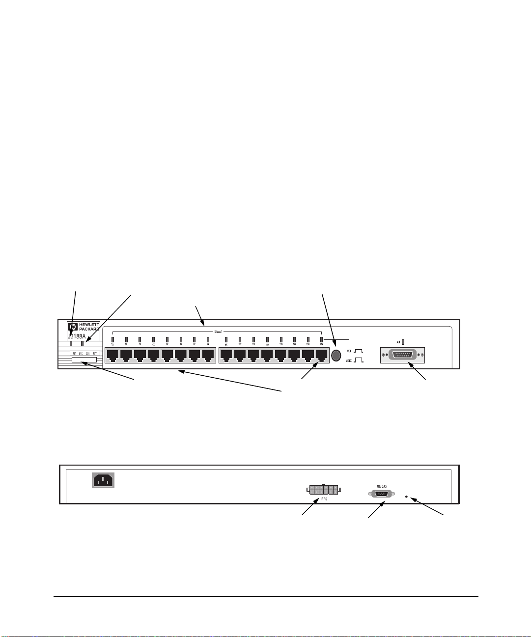
F
b
Back of the Hub
HP 10Base-T Hub-16M (J3188A)
The HP 10Base-T Hub-16M (J3188A) is a multiport repeater with 16 twistedpair ports, and one AUI port. With thi s hub, you can connect computers,
printers, and server s togethe r for file sharing. Thi s hub is com pliant with the
IEEE 802.3 Type 10Base -T sta ndard and supports both 802.3 and Ethernet
networks. The HP Hub-16M follows these two st andards by providing these
features:
■ lighting the hub’s port LED when it detects the connected device is
powered on and cable is good.
■ retransmitting data that did not suc cessfully arrive at the destination
device (collision detect ion).
■ temporarily disabling a port if a device connected to the port persistently
causes problems for the ne twork (auto-partioning).
ront of the Hu
System
Hub status LEDs (Fault, Security,
Collision, Activity)
RPS Status
Twisted Pair port
status LEDs
MDI/MDI-X
switch for
port 16.
Twisted-pair
ports
RPS connector Serial Port Password
AUI Connector for
External
Transceiver
Reset
Button
iii
Page 6

HP 10Base-T Hub-16M (J3188A)
Features
Network Connections • Sixteen RJ-45 ( twisted-pair ) ports to connect to end nodes or other devices.
• A Media Depend en t Interface (MDI) switch for Port 16 which allows you to connect
either an end node (MDI-X position) or to cascade a hub (MDI position) to the port ,
using a “straight-through” twisted-pair cable in both cases. Ports 1 through 15 always
are MDI-X. P ort 16 ha s a fact ory defa ult of MDI- X, but ca n be togg led to an MDI state
with the adjacent push-button.
• An AUI port in the fr ont of the hub for several t ypes of extern al transceiv ers, includ ing
ThinLAN, twisted-pair, and fiber-optic. The twisted-pair transceiver adds another RJ45 port for a total of 17 twisted-pair por ts on the hub. The fiber- optic transceiver
allows you to connect your hub to a fiber - optic backbone.
Easy-to-Use Design • Hub Status LEDs showing power, activity, collisions, RPS status, fault, securit y an d
Standards-Based
Compatibility
Other Features • Extended hub manag eme nt capabilities, providing a full set of management
port status prov ide quick, easy-to-read hub status in formation and tro ubleshooting
help.
• Metal brackets (included with the hub) that can be easily attached to the hub for
mounting the hub in a standard 19-inch telco rack.
• IEEE 802.3 Type 10Base-T standard compatibility to support both 802.3 and Ethernet
networks.
• Advanced embedded SNMP agent code enabling the hub to be managed remotely
from a network manag ement station that supports Simple Network Management
Protocol (SNMP) over IP (using the configured IP address) or Novell NetWare (IPX).
The agent code also provides HP EASE (Embedded Advanced Sampling Environment),
which samples network data for enhanced diagnostics from a network management
station.
commands tha t can be executed from an ASCII cons ole session. Thes e are describe d
later in this document in chapter 3, “Managing the Hub.”
• An RS-232 serial port that provi des out-of-band m an agement access including:
– An ASCII consol e to configure, monit or, and troubleshoot the hub.
– Variable baud rates on the hub’s out-of-band management RS-232 port, and
automatic sensing of the selected baud rate when connecting to a terminal device.
– Full V.22bis modem line control for remote out-of-band management access to the
hub.
– Updatable firmware that enables enhancements to be downloaded either from a
computer attach ed to the out-of-band management port or over the network.
• A Redundant Power Supply (RPS) connector that enables an RPS to be connected to
the hub, providing an alternative redundant power source.
• Advanced inte grated design including an Intel i960 RISC processor, 1 megabyte RAM,
and 512 kilobyte s of fl ash EEPRO M for conf igur atio n and futur e up gr ade c apab iliti es.
iv
Page 7

Contents
1 Installing the Hub
Installing and Configuring Your Hub . . . . . . . . . . . . . . . . . . . . . . . . . . . 1-2
1. Verify included parts . . . . . . . . . . . . . . . . . . . . . . . . . . . . . . . . . . . . . . . 1-2
2. Connect the external transceiver . . . . . . . . . . . . . . . . . . . . . . . . . . . . 1-2
3. Verify the hub operates correctly . . . . . . . . . . . . . . . . . . . . . . . . . . . . 1-2
4. Mount the hub . . . . . . . . . . . . . . . . . . . . . . . . . . . . . . . . . . . . . . . . . . . . 1-5
5. Connect the hub to your network . . . . . . . . . . . . . . . . . . . . . . . . . . . 1-7
Connecting Devices to the Hub . . . . . . . . . . . . . . . . . . . . . . . . . . . . . . . . 1-8
Connecting Hubs Together . . . . . . . . . . . . . . . . . . . . . . . . . . . . . . . . . . . 1-8
Interpreting LED Status . . . . . . . . . . . . . . . . . . . . . . . . . . . . . . . . . . . . . . 1-11
Interpreting Hub Status LEDs . . . . . . . . . . . . . . . . . . . . . . . . . . . . . . . . 1-12
Interpreting Port Status LEDs . . . . . . . . . . . . . . . . . . . . . . . . . . . . . . . . 1-13
2 Troubleshooting
Troubleshooting Approaches . . . . . . . . . . . . . . . . . . . . . . . . . . . . . . . . . . . 2-1
Using a Checklist to Diagnose the Hub . . . . . . . . . . . . . . . . . . . . . . . . . 2-2
LED Operation . . . . . . . . . . . . . . . . . . . . . . . . . . . . . . . . . . . . . . . . . . . . . . . . 2-3
Hub Maintenance Tasks . . . . . . . . . . . . . . . . . . . . . . . . . . . . . . . . . . . . . . . 2-5
Testing the Hub Only . . . . . . . . . . . . . . . . . . . . . . . . . . . . . . . . . . . . . . . . 2-5
Clearing a Password for the ASCII Console . . . . . . . . . . . . . . . . . . . . . 2-5
Running Connectivity Tests . . . . . . . . . . . . . . . . . . . . . . . . . . . . . . . . . . . 2-6
Obtaining Firmware Enhancements . . . . . . . . . . . . . . . . . . . . . . . . . . . . 2-6
3 Managing the Hub
Setting up the ASCII Console . . . . . . . . . . . . . . . . . . . . . . . . . . . . . . . . . . 3-1
Starting the Console . . . . . . . . . . . . . . . . . . . . . . . . . . . . . . . . . . . . . . . . . 3-3
Console Command Reference . . . . . . . . . . . . . . . . . . . . . . . . . . . . . . . . . . 3-4
v
Page 8

A Cables and Connectors
Recommended Cables . . . . . . . . . . . . . . . . . . . . . . . . . . . . . . . . . . . . . . . . A-1
Twisted-Pair Cable/Connector Pin-Outs . . . . . . . . . . . . . . . . . . . . . . . A-3
Twisted-Pair Cable for Hub-to-Compu ter Network Connection . . . . A-3
RS-232 Connector and Cable Pin-Outs . . . . . . . . . . . . . . . . . . . . . . . . . A-4
Minimum Cable Pinout for ASCII Console Connection . . . . . . . . . . . A-5
RS-232 Modem Cable . . . . . . . . . . . . . . . . . . . . . . . . . . . . . . . . . . . . . . . A-5
Twisted-Pair Cable Pin Assignments . . . . . . . . . . . . . . . . . . . . . . . . . . A-6
B Specifications
Physical . . . . . . . . . . . . . . . . . . . . . . . . . . . . . . . . . . . . . . . . . . . . . . . . . . . B-1
Electrical . . . . . . . . . . . . . . . . . . . . . . . . . . . . . . . . . . . . . . . . . . . . . . . . . B-1
Environmental . . . . . . . . . . . . . . . . . . . . . . . . . . . . . . . . . . . . . . . . . . . . . B-1
Connectors . . . . . . . . . . . . . . . . . . . . . . . . . . . . . . . . . . . . . . . . . . . . . . . . B-2
Electromagnetic . . . . . . . . . . . . . . . . . . . . . . . . . . . . . . . . . . . . . . . . . . . B-2
C Modem Configuration
D Network Addressing
Communication Between the Hub and Network Management Station
D-1
IPX Addressing for Novell NetWare . . . . . . . . . . . . . . . . . . . . . . . . . . . D-2
IPX Addressing Notes: . . . . . . . . . . . . . . . . . . . . . . . . . . . . . . . . . . . . . . D-2
IP Addresses for IP and Non-IP Networks . . . . . . . . . . . . . . . . . . . . . D-2
Globally Assigned IP Network Addresses . . . . . . . . . . . . . . . . . . . . . . D-2
Device IP Configuration . . . . . . . . . . . . . . . . . . . . . . . . . . . . . . . . . . . . . D-3
Using BOOTP . . . . . . . . . . . . . . . . . . . . . . . . . . . . . . . . . . . . . . . . . . . . . . . . D-4
The BOOTP Process . . . . . . . . . . . . . . . . . . . . . . . . . . . . . . . . . . . . . . . . D-4
BOOTP Table File Entries . . . . . . . . . . . . . . . . . . . . . . . . . . . . . . . . . . . D-5
E Backup Links
How Backup Links Work . . . . . . . . . . . . . . . . . . . . . . . . . . . . . . . . . . . . . . E-1
Limitations . . . . . . . . . . . . . . . . . . . . . . . . . . . . . . . . . . . . . . . . . . . . . . . . E-2
vi
Page 9

Additional Notes . . . . . . . . . . . . . . . . . . . . . . . . . . . . . . . . . . . . . . . . . . . E-2
Examples of Backup Links . . . . . . . . . . . . . . . . . . . . . . . . . . . . . . . . . . . . E-3
How the Backup Function Works . . . . . . . . . . . . . . . . . . . . . . . . . . . . . E-3
Configuring a Backup Link . . . . . . . . . . . . . . . . . . . . . . . . . . . . . . . . . . . . E-5
Configuration/Installation Sequence . . . . . . . . . . . . . . . . . . . . . . . . . . E-5
Identifying the Backup Link . . . . . . . . . . . . . . . . . . . . . . . . . . . . . . . . . . E-6
Indications of Backup Link Activation . . . . . . . . . . . . . . . . . . . . . . . . . E-6
Reactivating the Primary Link . . . . . . . . . . . . . . . . . . . . . . . . . . . . . . . . E-7
F Security Information
Understanding Network Security . . . . . . . . . . . . . . . . . . . . . . . . . . . . . . . F-1
How Intruder Prevention Works . . . . . . . . . . . . . . . . . . . . . . . . . . . . . . . F-2
How Eavesdrop Prevention Works . . . . . . . . . . . . . . . . . . . . . . . . . . . . . F-2
Authorized MAC address . . . . . . . . . . . . . . . . . . . . . . . . . . . . . . . . . . . . . F-2
Setting Inbound Security with Intruder Prevention . . . . . . . . . . . . . F-4
Auto Port Disable . . . . . . . . . . . . . . . . . . . . . . . . . . . . . . . . . . . . . . . . . . . F-5
Send Alarm . . . . . . . . . . . . . . . . . . . . . . . . . . . . . . . . . . . . . . . . . . . . . . . . . F-5
Setting Outbound Security with Eavesdrop Prevention . . . . . . . . . . F-6
G Safety and Regula tory Statements
Mounting Precautions . . . . . . . . . . . . . . . . . . . . . . . . . . . . . . . . . . . . . . . . G-1
Power Precautions . . . . . . . . . . . . . . . . . . . . . . . . . . . . . . . . . . . . . . . . . . . G-2
Safety Information . . . . . . . . . . . . . . . . . . . . . . . . . . . . . . . . . . . . . . . . . . . G-3
Informations concernant la sécurité . . . . . . . . . . . . . . . . . . . . . . . . . . . G-4
Hinweise zur Sicherheit . . . . . . . . . . . . . . . . . . . . . . . . . . . . . . . . . . . . . . G-5
Considerazioni sulla sicurezza . . . . . . . . . . . . . . . . . . . . . . . . . . . . . . . . G-6
Consideraciones sobre seguridad . . . . . . . . . . . . . . . . . . . . . . . . . . . . . G-7
Safety Information (Japanese) . . . . . . . . . . . . . . . . . . . . . . . . . . . . . . . G-8
Regulatory Statements . . . . . . . . . . . . . . . . . . . . . . . . . . . . . . . . . . . . . . . G-9
vii
Page 10

Page 11

Installing the Hub
This chapter describes how to install the hub. Topics in this chapter include
■ installing and configuring the hub
■ connecting devices to the hub
■ connecting hubs together
■ interpreting hub LEDs
1
Page 12

Installing the Hub
Installing and Configuring Your Hub
Installing and Configuring Your Hub
To install and configure your hub, you must complete five basic tasks. They
are:
Installing the Hub
■ locating and verifying the necessary parts
■ connecting an external transceiver (if necessary)
■ connecting the hub to a power source
■ mounting the hub
■ connecting the hub to your network
1. Verify included parts
Each Hub-16M has the following components shipped with it:
■ HP 10Base-T Hub-16M (J3188A) Installation and Reference Guide—
this manual (J3188-90001)
■ A U.S./Canada/Mexico (8120-1378) power cord.
■ Accessory kit (5064-2 05 3) :
• bumper feet (4)
• hub-to-rack screws 10-32 (4)
• bracket-to-hub screws 10-32 (4)
• nylon fini shing washer (4)
• bracket-to-hub screws (2)
• AUI retainer assembly
1-2
2. Connect the external transceiver
Because of the way the external transceiver protrudes out from hub once it is
connected, you may wan t to i ns tal l th e ex te rn al tr ansceiver before insta l li n g
the hub. Inspect your installation site and identify whether enough room will
be available for the external transceiver to be connected. Then see your
external trans ceiver guide for i n stallation instruct ions.
3. Verify the hub operates correctly
Before mounting the hub, connect it to a power source and verify the hub will
operate correctly.
Page 13
Installing and Configuring Your Hu b
Installing the Hub
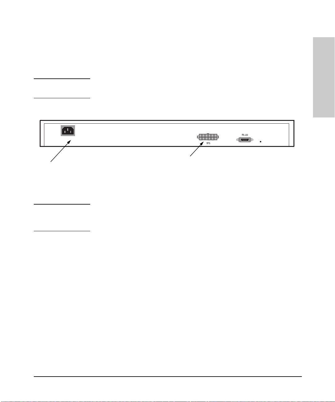
1. Plug the power cord into the hub’s powe r cord recepta cle and into an AC
(alternating current) power source. If you are using an RPS as your
primary power source, refer to the Cisco RPS User Guide for specific
instructions.
Note If your RPS is the p rimary power source for the hub, disc onnect the AC powe r
cord connected directly to the hub for proper opera tion.
(Optional) Connect Redundant Power Supply connector
If not connecting a Redundant Power Supply,
connect included power cord here and to an
alternating current power source.
cord clip here.
Installing the Hub
Note The hub does not have a power switch; it is powered on when the power cord
is plugged in. HP recommends that you only use one power source at a given
time.
1-3
Page 14

Installing the Hub
Installing and Configuring Your Hub
2. Check the LEDs on the hub’s front panel. When the hub is powered on, it
performs a power-on self te st. See the table below for the L ED pattern
that occurs during the self test.
Installing the Hub
On for 20 seconds,
then enters
normal operating
state.
On for five
seconds, then
enters normal
operating
state.
On for 20 seconds,
then enters
normal operating
state.
LED Pattern
Port LEDs,
Fault, Security,
AUI
Activity,
Collision, RPS
System Stays ON.
ON for approxim ately 20 seconds, then enters normal oper ating
state.
ON for approximately five seconds, then enters normal operating
state.
Note that once you have connected cables to the hub, a Port LED stays
on if link beat has been detected at the port. A Port LED turns off if link
beat is not detected. The AUI port stays on if it is enabled.
When the self test com pletes s uccessful ly, th e LEDs go into their normal
operational states. If a hub hardware fault exists, the hub will not
complete self test. This will be indic ated by an abnormal LED pattern.
1-4
If the self test time elapses and the Fault LED continues to stay on instead
of turning off, the h ub may have an error condi ti on . If re pe ati n g th e sel f
test does not correct the problem and the Fault LED still stays continuously on, contact your reseller for replacement information. After the hub
has passed its self test, you are ready to mount the hub.
Page 15

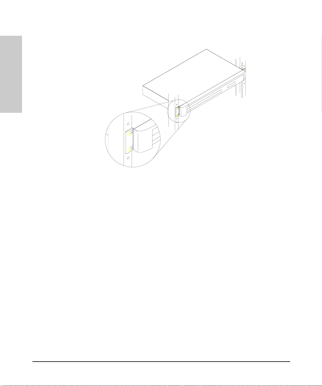
4. Mount the hub
Installing and Configuring Your Hu b
Installing the Hub
The HP Hub-16M can be mounted in two ways:
1. in a rack or cabine t
2. on a table
The hardware for mounting the hub is included in the accessory kit
(5064-2053) packed with the hub. Before mounting the hub, unplug it.
See Appendix G, “Safety and Regulatory Standards,” for general mounting
precautions.
Rack or Cabinet Mounting
Warning The rack or cabinet should be adequately secured to prevent it from
becoming unstable and/or falling over. Please see Appendix G, “Safety
and Regulatory Standards,” for precautions and warnings associated with rack
mounting.
1. Using a Phillips T-1 0 screwdriver, attach the mounting brackets to the hub
with #10-32 x 7/16" silver scre ws (included in th e accessory kit).
2. Position the hub in the rack or cabinet and slide it up or down unt il the
rack holes line up with the bracket holes.
3. Then attach the hub to the rack with the #10-32 x 5/8" black screws and
black nylon washers included in th e accessory kit with a Phillips crosshead screwdriver. (Some cabinets require number 12-24 screws instead.
Make sure you have screws that fit your cabinet or rack before mounting
the hub.)
Installing the Hub
1-5
Page 16
Installing the Hub
Installing and Configuring Your Hub
Installing the Hub
1-6
Table Mounting
To place the hub on a table or other horizontal surface, no special tools are
necessary. Apply the fo ur feet included in the accessory kit onto the bottom
of the hub. Be certain to pick a sturdy table in an uncluttered area. You may
want to secure the hub’s cabl es to t he leg of the ta ble to prev ent p eople from
tripping over them.
Page 17

Installing and Configuring Your Hu b
5. Connect the hub to your network
Installing the Hub
Reconnect the hub to either an AC power source or the RPS, depending on
which source you are using . With the hub mounted, you are now ready to
connect the hub to your network. Typical hub connections are:
■ hub-to-device connections. Connecting to network devices such as
computers, and printers.
■ hub-to-hub connections. Connecting to another HP 10Base-T hub, or
other Ethernet hub.
■ hub-to-network backbones. Connecting to a network backbone.
This section describes the different ways you can connect your hub to your
network.
Installing the Hub
1-7
Page 18
Installing the Hub
Installing and Configuring Your Hub
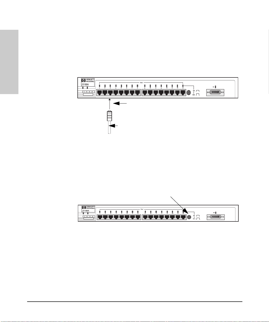
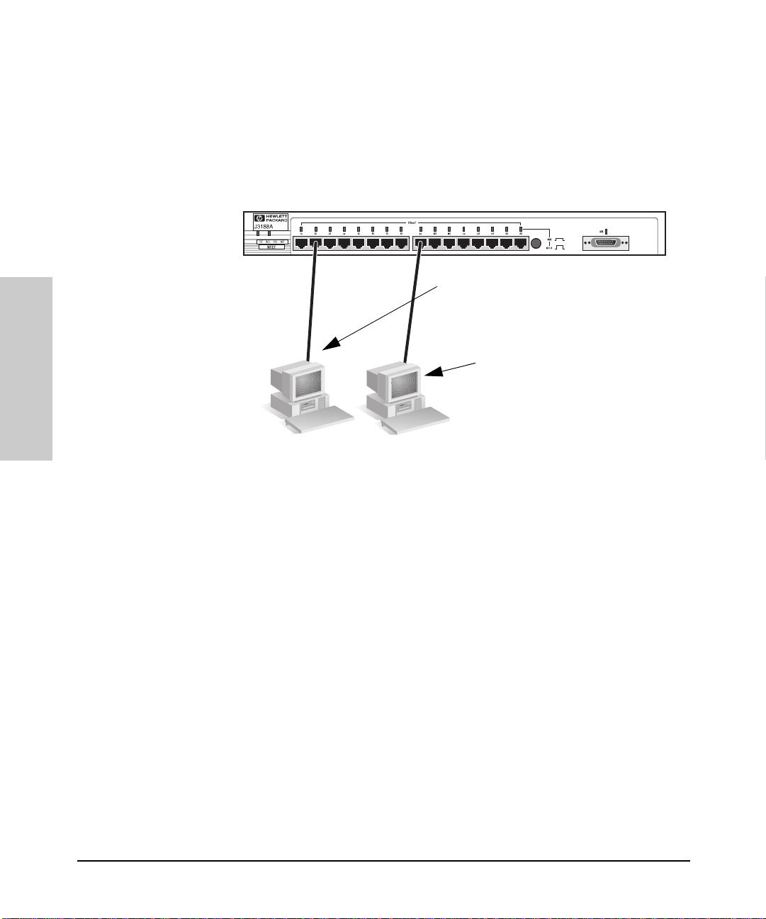
Connecting Devices to the Hub
To connect a device to the hub, push the RJ-45 plug into the RJ-45 jack until
the tab on the plug clicks into place.
Installing the Hub
RJ-45
Connector
unshielded twisted-pair cable
Category 3, 4, or 5
Cat 3, 4 maximum distance: 100 meters
Connecting Hubs Together
Twisted-Pair Cascade Connections
To expand your network, the hub can be connected to other hubs with
straight-through cable by using the Media Dependent Interface (MDI) switch.
MDI/MDI-X switch
The MDI/MDI-X switch controls h ow the si gnals are s ent through the twiste dpair cable connected to Port 16. The hub is shipped with the switch in the MDIX position. The switch has two positio ns:
■ In the MDI posit ion, use Port 16 to connect your hub to another hub. In
this position, the hub reverses the Tx and Rx port pairs for you. This allows
you to use “strai ght-through” ca ble rather than “cross-over” cable t o
connect two hubs together. The cable can be up to 100 meters in length.
■ In the MDI-X position, use Port 16 to connect your hub to a PC or similar
device using “straight-through” cable.
1-8
Page 19
Installing and Configuring Your Hu b
Installing the Hub
In the following illustration, the first hub is connected to two end nodes and
to a second hub. Note the second hub shows Port 16 connecting to a PC, using
a straight through cable with the port in the MDI-X position.
StraightThrough
Cable from
Hub to PCs
Hub attached to
Port 16: switch in
MDI position and
straight-through
cable is used.
Up to 100 meters
Installing the Hub
PC attached to
Port 16: switch in
MDI-X position
and straightthrough cable is
used.
ThinLAN Connections
With an HP ThinLAN External Transceiver for 10Base2 netw orks, you can
connect your hub or a stack of hubs to a thin LAN network. The following
illustration shows a hub with an HP ThinLAN E xternal Transceiver.
1-9
Page 20
Installing the Hub
Installing and Configuring Your Hub
Installing the Hub
You can connect u p to 30 hubs t ogether on a c ommon ThinLA N segment. The
ThinLAN segment can include a com puter attach ed to a hub at one end of the
segment that can communicate with a computer attached to another hub at
the other end of the segment. By using the BNC port on the module, the
maximum repeater hop-count increment through the entire segment is only
two. The following illustration shows you how to connect three hubs together
from one ThinLAN port to another.
50-ohm
terminator
ThinLAN coax
connecting the
hubs together
50-ohm
terminator
Hub-16M
Hub-16U
HP AdvanceStack
10Base-T Hub-24
Note Each ThinLAN cab le se gment m ust b e ter minat ed u sing a 50- oh m termin at or
at each end. In the illustration above, a 50-ohm terminator is placed at each
end of the cable segment.
1-10
Page 21
Interpreting LED Status
Connecting the Hub-16M to a Fiber-Optic Backbone
Installing the Hub
With an HP Fiber-Optic external transceiver for 10Base-F L networks, you can
connect your hub to a fiber-optic backbone. The following illustration shows
a hub with an HP Fiber -Opti c ex ter n al tr an sce iv er co n ne cte d to a f i be r- o pt ic
backbone:
Fiber-optic
cable to a
fiber-optic
backbone
HP J2606A Fiber-Optic
For more information about cabling configuration, see the documentation
accompanying the opt ional transceiver modules.
Interpreting LED Status
Installing the Hub
Two types of LEDs exist on the hub. They are:
■ Hub Status LEDs. These LEDs reflect certain conditions that exist on the
hub at large and are not explicitly referring to a give n port.
■ Port Status LEDs. These LEDs reflect basic conditi ons (for example, Link
Beat being enabled) that exist on a specific port.
Status information for both are described in the following tables.
1-11
Page 22

Installing the Hub
Interpreting LED Status
Interpreting Hub Status LEDs
The hub status LEDs indicate whether the hub is functioning properly. For
further details on error conditions indicated by the Status LEDs, see chapter
2, “Troubleshooting”.
LED State Meaning of LED
Installing the Hub
SYSTEM
(Power)
(green)
ACT
(Activity)
(green)
FLT
(Fault)
(Orange)
SEC
(Security)
(Orange)
RPS
(RPS)
(green)
COL
(Collision)
(orange)
On The hub is receiving power.
Off The hub is not receiving power.
Flickering ON while a pack et is being transm itted. Normall y, the LED appear s
to flicker. In heavy traffic, it may app e ar on all the time.
On
Off
Flash
On
Off
Flash
On
Off
Flickering This LED is on while a collision is detected. If it appears on
An error has been detected on the hub.
No error has been detected on the hub.
Flashes simultaneously with port LEDs, indicating the port is
partitioned.
A security violation has occurred.
Hub security has no t be en violated.
Flashes simultaneously with port LEDs, indicating the port had a
security violation.
The RPS is providing power.
The RPS is not providing power.
continuously (with no flicker), it is a possible indicator of a network
fault or an imp roperly termin ated cable.
1-12
Page 23

Interpreting Port Status LEDs
Installing the Hub
Interpreting LED Status
The following table provides LED port information.
LED State Meaning of LED
Twisted-pair
Port (green)
AUI
Port (green)
* The slow flash is approximately once every 1.5 seconds.
On Link beat is detected from the attached node.
Off The port is not receiving the link beat signal from the attached
Slow
Flash*
On The AUI port is enabled.
Off The AUI port is di sa b led .
Slow
Flash
node.
The port has been auto-partition ed. This port has been auto-
partitioned (disabled) due to excessive collisions. This port will
reenable when the connected device no longer causes
collisions.
The port has been auto-partition ed.
Installing the Hub
1-13
Page 24

Page 25

Troubleshooting
This chapter describes ways to troubleshoot the hub. Topics covered are:
■ troubleshooting approaches
■ using a checklist to diagnose the hub
■ interpreting the LED pattern during self test
■ hub maintenance tasks
Troubleshooting Approaches
There are three primary ways to diagnose hub problems:
■ By checking the LEDs on the front of the hub as described in the section,
“Using a Checklist to Diagnose the Hub” later in this chapter.
■ By using the ASCII console’s diagnostic functions as described in chapter
3, “Managing the Hub.”
■ By using the CiscoView network management application as described in
the CiscoView online help.
2
Page 26

Troubleshooting
Using a Checklist to Diagnose the Hub
Using a Checklist to Diagnose the Hub
Use the following table to diagnose t he problem with your HP Hub-16M.
Problem Solution
How do I reset the hub? Remove the plug on th e power cord from the
None of the LEDs are on. Verif y that the power cord is plugged into an
Troubleshooting
I lost the password. Press the password reset button for 10 seconds.
IP configuration errors have been
reported.
I want to see if each cable is connected
correctly.
A user can’t send data to another user. Use the Connectivity tests in the ASCII console
power source and reconnect it.
active power source and to the hub. Make sure
these connecti on s ar e sn ug . Tr y p owe r cy cl ing
the hub by unplugging and plugging the hu b
back in.
If the Power LED is still not on, verify the AC
source works by plug ging another device int o
the outlet. Or try plugging the hub into a different
outlet or try a different power cord.
If this condition persists, call your
HP-authorized LAN dealer or HP representative
for assistance.
See page 2-4 for more details.
Use the ASCII console’s IP Conf iguration
function as described in the ch apter 3,
“Managing the Hub.”
Run TEstlink. See the command description in
chapter 3, “Managing the Hub.”
or in CiscoView to test the cabling. The tests are
described in this chapter.
2-2
The Fault LED is on . Remove the plug on the power cord from the
The Security LED is flashing. How do I
get it to stop?
power source and rec onnect it. If problem
persists, the device has an internal failure.
Contact your HP aut ho r iz e d dealer or reselle r .
Use the ASCII console or C iscoView to view t he
intruder log an d clear the security violations.
Most problems with the hub can be diagnosed using t he LEDs on its front
panel. The following section describes the normal LED pattern during selftest, and LED patterns that indicate error conditions on the hub.
Page 27

Troubleshooting
LED Operation
LED Operation
The tables on the following pages list the hub’s LEDs, their possible states,
and diagnostic tips to resolve any error conditions.
LED patterns indicating problems Diagnostic Tips
Power Coll Por t L ED Sec Fault RPS
OFF** ***Verify that the power cord is plugged
into an active power source and to the
hub. Make sure these connections are
snug. Try power cycling the hub by
unplugging and plugging the hub back
in.
If the Power LED is sti ll not on, verify the
AC source works by plugg ing another
device into the outlet. Or try plugging
the hub into a different outlet or try a
different power co rd.
If this condition persists, call your
HP-authorized LA N dealer or HP
representative for assistance.
ON*OFF***Check cabl ing on the in dica ted po rt a ll
the way out to the device attached to
that port. Faulty wiring or a bad
connection could exist somewhere in
that connecti on.
The end node or hub attached to the
port is off.
The port may be disabled. Use the
ASCII console or management
application to enable the port.
Troubleshooting
If Port 16, check the position of the
MDI/MDI-X switch. See the figure in
chapter 1 that details the MDI/MDI-X
switch.
ON ON * * * * Very frequent collis ions a re occu rring,
which could in dicate a network fa ult or
improperly ter m inated cable.
*This LED is not important for the diagnosis.
2-3
Page 28

Troubleshooting
LED Operation
LED patterns indicating problems Diagnostic Tips
Power Coll Por t L ED Sec Fault RPS
ON * Fast
Flash
ON * Slow
Flash
ON * * Fast
ON * * * ON * The hub has failed its self-test. Power-
Troubleshooting
ON** **OFFThe internal power supply is operating
ON** **ONThe internal po wer supply has failed or
Fast
**A security violation has occurred on
Flash
*Slow
Flash
**Network management security
Flash
the port that is flashing. See SEcure
command for definition and details in
Chapter 3.
* The port has been aut o- partitioned
because of an excessive collision
condition. Ch eck cable connections
and status of attached network devices
for causes of the excess collisions. The
hub will automatically recover after
certain IEEE 802.3 criteria are
successfully met.
violation occurred. See SEcure
command for details.
cycle the hub. If this condition persists,
call your HP-authorized LAN deal er o r
HP representative for assistance.
properly and the RPS is not being used.
has been unplugged and the RPS has
been activated as the current
operating po w er supply.
2-4
*This LED is not important for the diagnosis.
Page 29
Troubleshooting
Hub Maintenance Tasks
Hub Maintenance Tasks
There are several hub maintenance tasks you can perform. They include:
■ testing the hub only
■ clearing a password from the ASCII console
■ running connec tivity tests
Each of these tasks is described in the following sections.
Testing the Hub Only
If you believe that th e hub is not operat ing co rrectly, remove and re insert the
power cord for that hub. Th is procedure will cause the hub to complete its
power-on self-test. If any erro r conditions exist in the hub, the LEDs should
display the condition.
Clearing a Password for the ASCII Console
You can use the Password Reset button to clear a forgotten console password
that was previously configured on the hub. The password is configured from
the ASCII console.
Password
Reset
To clear the password, follow these steps:
1. Verify the hub has powered-up, passed power-on test, and that the System
LED is lit.
Troubleshooting
2. Press the Password Reset button on the bac k of the hub for 10 seconds.
2-5
Page 30
Troubleshooting
Hub Maintenance Tasks
Running Connectivity Tests
Both the hub and cabling can be tested by running an end-to-end communications test -- a test that sends known data from one network device to another
through the hub -- such that you can verify that the data was correctly
transmitted between the devices.
PC sending test
packets.
PC responding to
the test packets.
Troubleshooting
2-6
See your LAN adapter’ s manual for information on running an end-to-end
communication test.
Obtaining Firmware Enhancements
In the future, Hewlett-Packard may provide improv ements to this product
through fi rmware up grades. T he upg rade code can be downloade d from a P C
attached to the hub’s RS-232 port or over the network. The update procedures
are described in documents that come with the firmware enhancements.
You can determine the current firmware version on the hub from the ASCII
console. Look for the SNMP Agent EEPROM version number to determine the
revision. When you access the console, the version number appears.
Page 31

Managing the Hub
This chapter desc ribes the fe atures avai lable fr om an ASC II console . Topics
include:
■ setting up the ASCII Console
■ console command re fe rence
The HP Hub-16M has SNMP that allows you to manage the hub using one of
the following utilities:
■ an ASCII console
■ CiscoWorks
■ any SNMP-compliant net work management product except HP
AdvanceStack Assistant.
3
Setting up the ASCII Console
You can begin a console session in the hub in the following ways:
■ directly, using a serial cable and a terminal (or a PC using a terminal
emulator)
■ remotely, using Telnet
■ remotely, using a modem and a terminal
The HP Hub-16M supports a single console session only. If a console session
is already running, a second console session can override the current console
session.
Page 32

Managing the Hub
Setting up the ASCII Console
Directly, Using A Serial Cable and a Terminal
To directly connect a terminal to a hub, follow these steps:
1. Connect an ASCII terminal, or a PC emulating an ASCII terminal, to the
RS-232 port using an RS-232-C “null modem” cable. (For pin-outs and
recommended cable s see Appendix A, “Cables and Connectors”.)
2. Switch on the terminal’s power (or switch on the PC’s power and start the
terminal emulation program). Configure the terminal for 8 bits per character, 1 stop bit, no parity, Xon/Xoff handshaking, and a baud rate of 38400,
19200, 9600, 4800, 2400, or 1200.
3. Press [Enter] several times for the => or Password prompt. The baud rate
for communication between the hub and the terminal is set automatica lly
when you press [Enter].
Remotely, Using Telnet
The HP Hub-16M supports a Telnet console session. Your Telnet syntax
depends on your TCP/IP software or your terminal server. By default, Telnet
is enabled. You can disable Telnet by using the IPconfig c onsole command
described on page 3-7.
To establish a Telnet session, follow these steps:
1. Verify that the hub has been configured with an IP address, and that it is
accessible via IP from your PC or workstation.
2. Enter the command telnet followed by the IP address or system name of
the hub, for example:
telnet 192.1.1.10
or
Managing the Hub
To end the Telnet session, type DI (the DIsconnect command) to t erminate
the console session. Or use your Telnet application’s command to close or quit
the Telnet session.
telnet your_hub
(Your Telnet syntax depends on your TCP/IP software or your terminal
server. You can use a system name if you have name resolution such as
DNS.)
3-2
Page 33

Setting up the ASCII Console
Managing the Hub
Remotely, Using a Modem and a Terminal
1. Use a full-duplex, asynchronous (character-mode) modem only.
2. Connect the modem to the hub’s RS-232 port using an RS-232-C modem
cable. (For pin-outs and recommended cables see Appendix A, “Cables
and Connectors”.)
3. Configure the modem a s desc ribed in the Appendix C, “Modem
Configuration.”
4. At the remote site, connect the terminal (or PC emulating a terminal) to
the remote mode m. Ma ke su re the ter minal a nd mod ems are f unct ion in g
properly, then establish the link between the terminal’s modem and the
hub’s modem according to the modem instructions.
5. Press [Enter] several times for the => or Password prompt. The baud rate
for communication between the hub and the modem is set automatically
when you press [Enter].
Starting the Console
The console session starts with a display similar to the following (the actual
version numbers may be different):
HP J3188A Hub-16M
ROM A.01.00
EEPROM A.01.00
HW A.01.00
Use console commands for hub configur ation.
Enter password:
If a password has not been assigned with the PAssword command, then you
are not prompted for your password here.
If a console session is currently active, then you are prompted to break the
current active console session .
A console session is currently active.
Do you want to break in? (Y/[N]) Y
Connecting…
Enter a console command, or HE or? for help.
=>
Managing the Hub
3-3
Page 34

Managing the Hub
Console Command Reference
Console Command Reference
Enter at least the firs t two l ett er s of a co mm and to e xe cute i t, such as HE for
the Help command. The Help command displays a screen like the following,
listing all commands.
Syntax Conventions on Help Screen:
<> – Indicates a required parameter.
[ ] – Indicates an option al parameter.
Managing the Hub
| – Used as a separator between acceptable variable values.
For example, SE <port|SHow|CLear> indicates that either a port ID, or the characters SH
or CL, must be entered after the SE command.
The commands are described in the rest of the chapter.
HElp [cmd] or? [cmd]
To see the help screen shown abo ve or, if you include a specific
command, the syntax and description of that specific console
command. For the [cmd] parameter, use the first tw o letters of th e command
you wish to see.
Example:
3-4
HE ST (This displays help for the Status c ommand.)
Page 35

BAckup
Console Command Reference
Managing the Hub
To configure one of the hub’s ports for dedicated use in a backup
(redundant) link to another hub.
An HP Hub-16M allows you to use any two of its network ports for a redundant
link to another hub in your network. The backup link normally carries no
traffic, but it is automatically activated if the primary link fails. Note that any
of the ports can be the backup port to any other port.
When you enter the Backup command, you are prompte d for these values:
Default Description
Backup Port Disabled The port used for the backup link. Enter the port ID.
Primary Port None The port used for the primary lin k . Enter the port ID.
Remote MAC
address
Seconds Between
Test Packets
Consecutive
Failures
000000-000000 The 12-digit hexadecimal MAC address of the hub at
1 second How often you want the hub to send an IEEE 802.2
2 failures The number of consecutive Test packet response
Or, enter DI (for disable) if you wish to remove an
existing bac kup link configuration.
the remote end of the critical link.
Test packet to the remote hub over the primary lin k.
failures that will trigger activation of the backup link.
For example, enter 5 t o activate the backup lin k on
the fifth failure.
The hub monitors the prim ary link by sending IEEE 802.2 Test pack ets at the
specified frequency to the specif ied remote h ub. If “n” consecutiv e Respons e
packets are no t returned from th e remote hub, the p r imary port is disabled
and the backup port is ena bled.
When the primary link is repaired, you must re-enable the primary port by
using the Port command. It is not automatically re-enabled. When the primary
port is re-enabled, the backup port is disabled automatically and returned to
backup mode. See the appendix on Backup Links. This appendix also covers
more information on ba ckup links, including requirements, limitations, and
sample topologies.
Managing the Hub
3-5
Page 36

Managing the Hub
Console Command Reference
CDpstatus
COunters
To enable or disable the Cisco Discovery Protocol (CDP). The command takes
either an ON or an OFF argument. Th e initial setting is ON. O N enables the
protocol. OFF disables it. If no option is chosen, the current status is shown.
To display network activity counters for each network port, the hub’s
SNMP agent, and the global count for all ports.
The port counters are from the IEEE 802.3 Repeater Management
Specification. They are described below:
Counter Na me Definition Valid Range
Good Packets Number of error-free packets received. Less than 4000
packets per
second.*
Collisions Number of times the p or t was involved
in a collision. A single collision will be
counted by all ports involved, so the
total collision counters may be less than
the sum of the port counts.
Late Collisions Number of collisions which went
undetected by the sending end node.
Less than 2 times
the number of goo d
packets.
Less than.1% of
good packets.
Managing the Hub
CRC/Alignment
Errors
Giant Packets Number of packets larger than 1518
Broadcast Packets Number of packets addressed to
*The port counters in the ASCII console show totals, not number of packets per second. For the Good Packets and
Broadcast packets, display counters twice over a period of one section to see if the value falls in the valid range.
Number of packets transmitted
incorrectly and number of incorrectly
aligned packets.
bytes.
everyone in the network. These packets
consume CPU resources from each
node on the networ k.
Less than.1% of
good packets.
Less than.1% of
good packets.
Less than 200
packets per
second.*
Corrective Action if over Valid
Range
Decrease the traffic level by
using a switch to segment the
network.
Decrease the traffic level by
using a switch to segment the
network
Replace bad cabl es and/or
transceivers if problems persist.
Rarely, you may have a
defective LAN adapter.
Too many repeaters between
end nodes, or cables which are
too long, or bad cable.
This counter indicates faulty
cabling.
Update the LAN ada pter dri vers
on all nodes connected to the
port.
Decrease the number of nodes
in an IP subnet or IPX network
by using more routers. Consult
Novell Netware documentation
on how to reduce broadcasts in
an IPX network.
3-6
Page 37

DIsconnect
IPconfig
Console Command Reference
Managing the Hub
To terminate the console session and reset the console port baud rate
to be automatic ally sensed. The command also disconnects the phone link
if you accessed the console using modems.
To set IP (Internet Protocol) configuration parameters on the hub.
By default, the hub is configured to use BOOTP (Internet Boot Protocol) t o
automatically retrieve the IP parameters from a BOOTP server, and to enable
Telnet access to the hub’s console interface. Use this command if you want
to manually configure the IP address or disable Telnet.
The IP configuration must be carefully controlled. If each device’s IP address
is not unique on the network, severe network performance problems will
occur. A network administrator should maintain responsibility for the IP
settings. See Appendix D, “Netwo rk Addressing,” for information on setting
the IP configuration.
Note At the end of the process of changing the IP config uration, the hub will be
reset. This terminates the console session (and disconnects the phone line if
using a modem) and resets the con s ole port baud rate to be automatically
sensed. To restart a console session, when the reset process completes, press
[Enter] several times for the prompt.
When to Use IPconfig
If any of the following is true, the hub’s IP parameters must be configured,
either on a BOOTP server or on the hub through the console interface:
■ The hub will be managed remotely with a network management product,
such as CiscoWorks over an IP network (a network that uses IP communications, for example TCP/IP).
■ The network cable segme nts atta ched to the hub will be test ed usin g the
IP “Ping” test.
■ Telnet access to the hub is desired.
Managing the Hub
3-7
Page 38

Managing the Hub
Console Command Reference
Configuring for Network Management
If the hub is to be managed from a network management station, it must use
the same networking protocol as the network management station. You have
these choices:
■ Novell NetWare IPX
■ IP
Using Novell NetWare IPX
The HP Hub-16M is designed to automatically use Novell NetWare’s IPX
protocol. If you are using the hub on a Novell NetWare network, no configuration of the hub is required for it to communicate with a network management
station that is also using the IPX protocol.
The hub determines its IPX addr ess automatical ly from inform ation received
from a router or file server that is running IPX on the network, and from its
own MAC address, physical address, or Ethernet address). See your Novell
documentation for more information on IPX communications and addressing.
Using IP
You can use IP by using one of the following methods:
■ using BOOTP by adding an entry for the hub in the BOOTP table on your
BOOTP server, and enabling BOOTP thr ough the hub’s con sole interfac e
(this is the default setting)
■ using the console interface to configure the IP parameters
BOOTP is covered in Appendix D, “Network Addressing.”
Managing the Hub
To use the console interf ace to configure th e IP pa rameter s, ente r IP and th e
following text appears:
=>IP
Active IP parameters:
BOOTP protocol enabled: YES
Telnet access enabled: YES
IP address: 0. 0.0.0
Subnet mask: 0.0.0.0
Default router: 0.0.0.0
Time to live: 64
Change IP configuration? (Y/[N]):
The following table explains the IP parameters.
3-8
Page 39

Console Command Reference
Parameter Default Value Definition
BOOTP protocol
enabled
Telnet access
enabled
IP address 0.0. 0 .0 The IP address of the hub (written in the format X.X .X.X).
Subnet mask Must be supplied and
Default router 0.0.0.0 The IP address of the nearest IP router in your network. If no IP routers
Time to live 64 The number of IP routers a packet is allowed to cross before the packet
YES Keep or set this value to YES if you are using a BOOTP server to provide
YES Determine whether users are allowed to use Telnet to access the hub’s
depends on the class of IP
address that has been
entered.
the IP configuration to the hub. By default, the hub is configured to
automatically seek an IP address from a BOOTP server on the network.
This is done when the hub is powered on. If an IP address is not found,
the HP Hub-16M will seek an IP address every ten minutes until it finds
an IP address. Set this value to NO to disab le this BOOTP process.
If you are not using BOOTP to provide the hub’s IP configuration, you
should set this parameter to NO.
console interface.
Each X is a decimal number between 0 and 255 separated by a decimal
point. This add ress will be used unles s the BOOTP protocol is enabled.
The default value (0.0.0.0) disables IP communications on the hub when
BOOTP is also disabled.
The bit mask defining which portion of the IP address is the subnet
address, written in the format X.X.X.X. All the device s on your network
should use the same subnet mask. See your network administrator for
the correct value.
are in your network, enter the device’s own IP address.
is discarded. Increase this value if the hub will be sending IP packets to
a destination that is more than 64 routers aw ay. The maximum is 255.
Managing the Hub
Managing the Hub
MAnagers [SHow]
To configure the list of network man agement stations th at are authorized to access and manage this hub, and to specify which of those
stations should receive alarms. Use t he SHow option to display the current
list of authorized management stations without being prompted to edit the list.
The list consists of th e IP or IPX addr ess of the ne twork man agement station
and an indication of whether each management station should receive alarms
(indications of specific network events that are con figured for the hub from
3-9
Page 40

Managing the Hub
Console Command Reference
network mana gement— also called SN MP event alarms). The sta rt of the table
is shown below. Up to ten network management stations can be entered into
the table. Entry 0 (zero) is used for the “all managers allowed” entry.
ID Manager Address (IP or IPX) Receive Alarms?
0 All managers allowed NA
1
2
The hub is initially shipped with all network mana gement st ations a llowed t o
manage the hub, but the “all managers” entry does not identify where alarms
are to be sent. Specific addresses must be entered into the table to identify
where the alarms should be sent.
Note If you want to restrict wh ich manage ment stat ions are allowed to manage the
hub, delete entry 0. Then add the all owed management stations with the A
command.
At the interface prompt, enter MA; the current authorized managers list is
displayed and you ar e prompted to add or delete an entry in the list, or to enter
E to end your editing.
To add an entry, enter A at the prompt. Enter the IP or IPX address of the
network management station, or enter A to allow all managers to manage the
hub, then indicate at the next prompt whether this management station should
receive alarms generated by the hub. A new entry is added to the list.
Managing the Hub
3-10
Page 41

Console Command Reference
Managing the Hub
Example: To add the network management station with IP addr ess
190.40.101.10 to the list an d t o send alarms to th at sta tio n, th e pr ocess would
appear as follows:
Add entry (A), Delete entry (D), or End changes (E): A
Enter Manager Address, or (A) to allow all managers access: 190.40.101.10
Should this manager receive alarms: (Y/[N]):Y
Add entry (A), Delete entry (D), or End changes (E): E
Current authorized manager list:
ID Manager Address (IP or IPX) Receive Alarms?
0 All managers allowed NA
1 190.40.101.10 YES
2
To delete an entry, specify the ID number in the list corresponding to the
network management station to be deleted.
Example: To delete th e entry made in th e example above , the steps would b e:
Add entry (A), Delete entry(D), or End changes (E): D
Enter ID of entry to delete: 1
MEssageinterval
NEighbor
Add entry (A), Delete entry (D), or End changes (E): E
The table entry with I D 1 would now be a blank line.
To enter a new value that will indicate how much time, in seconds, should
lapse between transmissi ons of CDP messa ges. Displays the cu rrent inte rval
if no time is specif ied. Accep tabl e val ues ar e dec ima l nu mbers from 5 to 9 00
(seconds). The default value is 60 seconds.
Displays the other devices that are using CDP protocol.
3-11
Managing the Hub
Page 42

Managing the Hub
Console Command Reference
PAssword
To set or change the password on the hub. The Password is used to
prevent unauthorized access to the hub from network management stations,
and through the console interface. The hub is initially shipped without a
password. Follow the prompts t o enter a new password or to ch ange the
existing password. If you assign a passw ord, it is also used as the SNMP
community name.
If you decide to delete the password, enter the Password command, then press
[Enter] without entering any characters a t the password prompt.
Press and hold the Password Reset button for approximately 10 seconds to
clear a password.
Note After the password has been cleared, access to the hub from the ASCII console
and from SNMP management stations will no longer be password protected.
A new password can be assigned from the ASCII console or CiscoWorks.
PIng
To test the path between the hub and another device that responds to
IP packets. The hub sends Internet Control Message Protocol (ICMP) Echo
Request (Ping) packets to another node with the specif ied IP address and
waits for Echo Response packets in return.
When you run the Ping command, you will be prompted for:
Managing the Hub
■ the IP address of the dest ination device (in the format X. X.X.X)
■ the number of packets to send
■ the timeout value (the number of seconds to wait for a r esponse)
If any errors are re ported during this test, there may be a fa ult in the path used
during the test or in the destination device. For more information about testing
network links, see chapter 2, “Troubleshooting”.
3-12
Page 43

POrt <port> <ON/OFF>
To enable (set to ON) or disable (set to OFF) a hub port. The initial
setting for all ports is enabled (ON). You can use the Status command to check
the current status of all the ports. The < port> parameter can be:
■ twisted-pair port number
■ XCVR or XC for the AUI port
■ ALL or AL for all ports
Example 1: P0 7 OFF (Disables port 7)
Example 2: P0 AL ON (Enables all ports)
REset
To reset the hub and run a hub self-test. This command also resets all
the network statistic counters, and the time since the last reset. The current
configuration is unchanged. The hub is not accessible from network management software while it is being tested, but it continues to repeat data. If the
hub is faulty, at the end of the reset process, the Fault LED will stay on.
Console Command Reference
Managing the Hub
RObustness
This command also terminates t he console session (and disconnects the
phone line if you are using a modem to access the console) and resets the
console port baud rate to be automatically sensed . To r est art the console
session, first re-establish the phone link (if used), then press [Enter] several
times for the prompt.
Allows you to invoke options to improve the hub’s ability to tolerate network
problems resulting from excessive collisions. The configurable options are:
■ Intelligent Partition Recovery
■ Late Collision Monitoring
By default, the robustness fe atures are off. Th e Intelligent Partition Rec overy
option makes it difficult for a pro blem port to automatically re-enable itself
to send traffic on the network.
3-13
Managing the Hub
Page 44

Managing the Hub
Console Command Reference
The Late Collision Monitoring option monitors ports for excessive late
collisions. If monitored ports experience excessive late collisions, these ports
are disabled.
See the section on Auto-Partitioning in the chapter that provides the Product
Description.
SEcure <port|SHow|CLear>
To control or display the hub’s security configuration, and to clear
security violation indicators. The <port> parameter can be:
■ a twisted-pair port number only.
■ XCVR or XC for the AUI port.
■ ALL or AL for all ports
Security Configuration Parameter Definitions
The following security parameters are configurable on each of the hub’s
network ports. These parameter s are defined on the next two pages:
■ Address selection method, or authorized MAC address
■ Send alarm when intrude r detected
■ Eavesdrop preven tio n
An additional parameter, “Disable port when intruder detected”, is se t
automatically by your selection of the address selection method. See “Auto
Port Disable” in Appen dix F, “Security Information,” on this parameter.
Managing the Hub
Address selection method, o r authorized MAC address. This is the
method by which the hub automatically learns the address of the device that
is authorized to use the por t, or you can enter a specific address. The fol lowing
methods are configurable:
■ Learn Continuously—provides minimum port security (default secu-
rity state). The hub le ar ns th e ad dr ess o f the first devi ce at tached to the
port and makes it the authorized MAC address. If a different device is later
attached to the port, the new address is learned and becomes the authorized address. Eac h new device a ttached beco mes the autho rized devic e.
You can be informed of any such changes by setting the Send Alarm
parameter to YES. In that case, when a new address is detected, the
3-14
Page 45

Console Command Reference
Managing the Hub
Security and port LEDs flash, the intruder’s MAC address is displayed on
the console Status command screen, and an alarm is sent to the authorized
network management station(s) .
■ Use the First Address Heard—provides medium port security. The
hub learns the addre ss of the first de vice attached to the por t and mak es
it the authorized MAC addr ess. If you have any security configure d for the
port (Send Alarm and/or Eavesdrop Prevention parameters are set t o
YES), when a different device is la ter attached to the port, the new address
is registered as an “intruder address”; a security violation has occurred.
In that case, the port is automatically disabled, and the Security and
affected port L EDs flash. A n ala rm is al so sent to the au thorized networ k
management station(s) if the Send Alarm parameter is set to YES.
■ Assign an Address—provides the highest security. You enter the
address of the device that is a uthor ized to be at tac he d to th e p ort. If y ou
have any security configured for the port (Send Alarm and/or Eavesdrop
Prevention parameters are set to YES), when a different device is later
attached to the port, the new address is registered as an “intruder
address”; a security violation has occurred. In that case, the port is
automatically disabled, and the Security and affected port LEDs flash. An
alarm is also sent to the authorized network management station(s) if the
Send Alarm parameter is set to YES.
■ Port Security Off—disables port security. This is a convenient way to
remove the port security. It automatically sets the Send Alarm and Eavesdrop Prevention parameters to OFF (and therefore, the Disable Port
parameter will also be OFF).
Managing the Hub
Send Alarm when intruder detected. Configures the hub to send an
alarm (SNMP tr ap) to a network mana gement station whenever an
unauthorized address (an int ruder) is detected on the port. Note that for the
alarm to actually be sent, you must have first used the Managers command
to configure one or more network managers to receive alarms. See the
Managers command desc ription earlier in this chapter.
Eavesdrop prevention. Configures the hub to prevent the port from
hearing data that is intended for another port. Only the data packets that have
a destination address that matches the port’s authorized address are sent to
the port. If Eavesdrop Prevention is not enabled on all ports, the hub functions
like a repeater and every packet seen by the hub is forwarded to the nonEavesdrop Prevention ports. Se e Appendix F, “Security Information,” for a
detailed description of this feature.
3-15
Page 46

Managing the Hub
Console Command Reference
Configuring Security on a Single Port
To set or change the securit y configuration for a single p ort on the hub
(twisted-pair or AUI), enter
current security con fig uration is displayed, followed by a prompt to change
the configuration or n ot.
If you choose to change the configuration, you are then prompted for the
following parameters (de fined on the previous page ):
■ Address selection method, or a ut horized MAC address
■ You are first prompted if you want to change the address selection method
or the authorized address. Press [Enter] or enter N to retain the current
value. Enter Y to change the value and you are pro mpted t o select one of
the following methods:
– learn a ddress Continuously (enter C)
– use First address heard (enter F)
– Assign an address (enter A)
– port security Off (enter O)
■ Send alarm when intruder detected
■ Eavesdrop preven tio n
SE and the port’s ID; for examp le, SE 4. The port’s
Note To enable security on a port, a t least one of the parameters, Send Alarm or
Eavesdrop Prevention, must be set to ON.
Configuring Security on All Twisted-Pair Ports
To set or change the security configuration for all the twisted-pair ports
together, enter
Managing the Hub
same security configuration for all the twisted-pair ports, either at initial setup
or when you want to change the configuration for all the ports. You are
prompted whether to continue this process or not. If you choose to continue,
you are then prompted for:
■ Address selection method:
If you select First heard for al l ports (F), learn continuo usly for all ports (C) , or
security Off for all ports (O), the setting you select will be applied to all the
twisted-pair ports. If you enter F, the authorized address for each of the
twisted-pair ports will be the source address in the first packet received
from the attached devi ce. If you enter C, each of the twisted-pair ports will
continuously update the authorized address when th e attached devices
change. If y ou enter O, the security will be turned off for all the twisted-
3-16
SE ALL. This method is most useful when you are using the
Page 47

Console Command Reference
Managing the Hub
pair ports; that is, the security parameters will all be set to NO (configured
address selection methods, and learned or assigned addresses are not
changed).
If you select
Port
1
2
3
For each port, enter an address selection method (
assign Each port (E), a table like the followin g is displayed:
ADDRESS
SELECTION
METHOD
CONTINUOUS
CONTINUOUS
CONTINUOUS
AUTHORIZED
ADDRESS
NONE
NONE
NONE
F, C, or
a MAC address
F, or C), or a specific
MAC address, or press [Enter] to retain the current value. Continue this
process until all of the ports are displayed. If you do not want to configure
all twisted-pair ports, note that you can terminate the address selection
method by pressing [Enter] once. In either case, you are then prompted for
the settings for the Send Alarm and Eavesdrop Prevention parameters, as
described on the next page.
Managing the Hub
3-17
Page 48

Managing the Hub
Console Command Reference
■ Send Alarm when intruder detected? and Eavesdrop prevention?:
These parameters are defined earlier in the chapter under “Security
Configuration Parameter Definitions”.
The values you select for these parameters will be applied to all the
twisted-pair ports fo r which you have selected (or retained) the address
selection method.
Showing the Security Configuration
Enter the command SE SH to display the security configuration for all of the
hubs ports. A table like the following is presented:
ADDRESS
Port
SELECTION
METHOD
AUTHORIZED
ADDRESS
EAVESDROP
PREVENTION
SEND
ALARM
DISABLE
PORT *
1
2
3
CONTINUOUS
CONTINUOUS
FIRST HEARD
123456-890123
NONE
123456-789012
YES
NO
YES
NO
NO
YES
NO
NO
YES
The vertical bar b etween Send Alarm and Disa ble Port indicates that the va lue
for the Disable Port parameter is not directly configurable. This parameter is
automatically set by th e Address Selection Method. If the method is either
First Heard or Assigned, and if at least one of the other security parameters
is set to YES, the Disable Port parameter will be YES. If the method is
Continuous, the Disable Port parameter is always automatically set to NO .
Clearing Security Violation Indicators
Enter the command SE CL to clear any security violation indicators and to
Managing the Hub
“rearm” the indicators to be ready for the next intrusion. The indications are
slightly different between port security violations and network management
security violations, as describe d next.
For Port Security. The security violations are indicated by the Security
LED and the LED for the affected port blinking simultaneously, and the
intruder’s MAC address being added to the Status command screen for the
affected port. Security violations occur when a non-authorized address is
detected on a port and at least one of the intruder prevention parameters (Send
Alarm or Disable Port) is set to YES.
3-18
Page 49

Console Command Reference
For Network Management Security. The security viol ations are indicated
by the Security LED flashing and the violating network management station’s
address being displayed on t he Status command screen.
A network management security violation occurs when a network management station that is not on the authorized management station list attempts
to issue SNMP “set” commands to the hub, or when a network management
station uses an invalid password (SNMP community name) to access the hub.
See the Managers command description, earlier in th is chapter, for
information on the authorized management station list. By default, all network
management stations are allowed to manage the hub. Under this configuration, network management security violations will not occur.
Notes If the port was disabled because of a security violation
(Disable Port = YES), to re-enable the port you must enter the port ON
command for that port .
The Security Clear command does not remove the cause of the security
violation, for example the wrong device being attached to a port. Until the
cause is removed, the violation can reoccur immediately after issuing
the SE CL command. It may appear as if the violation indication was nev er
cleared.
Managing the Hub
SPeed <new speed>
Change the console port baud rate. Normally, the baud rate is
automatica lly sensed. Use this command if you want to set the baud rate
explicitly to 1200, 2400, 4800, 9600, 19200, or 38400. You will be prompted to
set the terminal’s baud rate to the same speed and to press Enter for the
prompt. Example SP 9600. (Sets the baud rate to 9600.)
STatus
To display status information for the hub. The status information
includes:
■ the time elapsed since the last reset ( see the Reset command),
■ the hub’s MAC address,
■ if a network manageme nt security violation has occu rred, the MAC
Managing the Hub
address of the violating network management station,
3-19
Page 50

Managing the Hub
Console Command Reference
■ Redundant Power Supply status:
• NOT CONNECTED means the RPS is not attached to the device.
• CONNECTED/FAULT means the RPS is attached but is reporting an
error.
• CONNECTED/GOOD means the RPS is attached with no errors, but
has not been enabled.
• CONNECTED/GOOD/ACTIVE means the RPS is attached with no
errors, and is active (the primary power supply is not operating and
the RPS has been initiate d as a backup system).
■ a table with the port inf ormation described as follows:
Status
Information
What It Means
Port The port ID. (Additionally, bkup indicates that the port is configured as the
Port Status The status of each port:
Link Beat Informs the hub of the presence of a device connected to it over twisted-
MAC address The unique 12-digit link-layer address for the hub. (Also called Ethernet
Managing the Hub
INTRUDER
ADDRESS
backup link, pri indicates that the port is the primary link—see the Backup
command).
ON means the port is enabled and is not auto-s egmented.
OFF means that the por t has been disabled by the Port command or
because of a security violation.
PARTITIONED means the port has been auto- partitioned.
(See “Auto-Partitioning” in the
Product Description.
ON/REVERSED means that reversed wiring polarity on the receive pair has
been detected on a twisted-pair cable and the hub has compensated.
pair cable.
address or physica l address.)
The address of a dev ice not authorized t o access the hub.
)
chapter that provides information on the
3-20
Page 51

Console Command Reference
Managing the Hub
TEstlink
To run a test of the link between the hub and another IEEE 802.3
device.
Note The destination device must be able to send an IEEE 802.2 Test Response
packet upon receipt of an IEEE 802.2 Test command packet. The HP Hub16M will respond with the correct packet.
You will be prompted for the 12-digit hexadecimal MAC address of the
destination device. You will then be prompted for the number of test packets
to send.
If any err ors are reporte d during thi s test, ther e may be a fau lt on the li nk being
tested or on the destination dev ice. For more information about testing
network links, see the chapt er 2, “Troubleshooting”.
3-21
Managing the Hub
Page 52

Page 53

Cables and Connectors
This appendix lists cables that have been tested and verified for use with the
HP Hub-16M. The following topics are covered:
■ recommended Ca bles
■ twisted Pair Cable/Connector Pinouts
■ RS-232 Connector and Cable Pinouts
It also includes minimum pin-out information so, if you wish to use an unlisted
cable, you can verify that the cabl es used in your installation are correctly
wired. Note that each pin-out does not necessarily match the pin-out for the
corresponding HP cable, but cables manufactured to follow the minimum pinout will function correctly.
Recommended Cables
A
The following table shows PC connections to the RS-232 port.
Console PC connection to the RS-232 port:
Purpose Cable Description Part No.
Connecting the
PC directly to
the module’s
RS-232 port
Connecting a
modem to the hub’s
RS-232 port
9-pin male RS-232 9-pin female to 9-pin
female null modem or “crossover” cable
25-pin male
25-pin female
25-pin fe male RS-232C 9-pi n female to 25-pin
RS-232C 9-pin female to 25-pin
male null modem or “crossover” cable
RS-232C 9-pin female to 25pin-female null modem or
“crossover” cable
male standard modem or
“straight-through” cable
F1047-80002 or
F1047-60901 or
5182-4794
24542G
(3 meters)
25442H
(3 meter)
HP 24542M
Page 54

Cables and Conn ectors
Recommended Cables
The following table shows net work connections to the hub.
Cable Function Cable Type HP Product Number
Network connections to the hub:
Hub to end node
connection or hub to
hub connection
using the MDI/MDIX switch
Cables and Connectors
* The maximum total length of any twisted-pair segment is 100 meters.
Twisted-pair
“straight-throu gh”
cable
92268A (4 pair, 4 meters)
92268B (4 pair, 8 meters)
92268C (4 pair, 16 meters)
92268D (4 pair, 32 meters)
92268N (4 pair, 300 meters)*
You can contact your HP authorized dealer or call HP at 1-800-538-8787 to
order these parts.
A-2
Page 55

Twisted-Pair Cable/Connector Pin-Outs
Cables and Connectors
Twisted-Pair Cable/Connector Pin-Outs
Twisted-Pair Cable for Hub-to-Computer Network
Connection
To connect PCs or other network devices to the hub, use a “straight-through”
10Base-T cable. The twisted-pa ir wires must be twisted through the entire
length of the cable. The wiring sequence must conform to AT&T 258A (not
USOC). See “Twisted- Pair Cable Pi n Assign ment s” at the en d of this ch apte r
for a listing of the signals used on each pin.
Cables and Connectors
Note Pins 1 and 2 must be a twisted pair.
Pins 3 and 6 must be a twisted pair.
Pins 4, 5, 7, and 8 are no t used in this application , although the y may be wire d
in the cable.
A-3
Page 56

Cables and Conn ectors
RS-232 Connecto r and Cable Pin-Outs
RS-232 Connector and Cable Pin-Outs
The Management Module’s RS-232 port connector is wired as depicted in the
following table.
Cables and Connectors
PIN US CCITT DIN
1 DCD 109 M5
2 Rx 104 D2
3 Tx 103 D1
4 DTR 108 S1
5 GND 102 6 DSR 107 M1
7 RTS 105 S2
8 CTS 106 M2
9 RI 125 M3
Use the RS-232 port to connect a PC to be used as the console. To make this
connection, you must use a null modem cable or you can use the minimum
cable pin-out described below.
This appendix lists cables that have been tested and verified for use with the
HP Hub-16M. It also includes minimum pin-out information so, if you wish to
use an unlisted cable, you can verify that the cables used in your installation
are correctly wired. Note that each pin-out does not necessarily match the
pin-out for the corresponding HP cable, but cables manufactured to follow
the minimum pin-out will fun ction correctly.
Note Incorrectly wired c abling is the most common cause of problems for LAN
communications. HP recommends that you work with a qualified LAN cable
installer for assistance with your cabling requirements.
A-4
Page 57

RS-232 Connector and Cable Pin-Outs
Cables and Connectors
Minimum Cable Pinout for ASCII Console Connection
Cables and Connectors
PC end
9-pin male
22Rx
33Tx
55GND
Hub end
9-pin male
RS-232 Modem Cable
Modem end
25-pin male
23Tx
32Rx
47RTS
58CTS
66DSR
75GND
8 1 CD OR DCD
20 4 DTR
Hub end
9-pin male Signal
22 9 RI
23 DRS–typically on V.24 (European) modems
(not connected)
A-5
Page 58

Cables and Conn ectors
RS-232 Connecto r and Cable Pin-Outs
Twisted-Pair Cable Pin Assignments
Twisted-Pair Straight-Through Cable
Hub End (MDI-X) Computer or Transceiver End
Signal Pins Pins Signal
(MDI)
Cables and Connectors
(receive +)
(receive –)
(transmit +)
(transmit –)
1
2
3
6
1
2
3
6
(transmit +)
(transmit –)
(receive +)
(receive –)
A-6
Page 59

Specifications
Physical
Width: 42.5 cm (16.8 in)
Depth: 23.8 cm(9.4 in)
Height: 4.36 cm (1.7 in)
Weight : 8 lbs and 7 oz. (8.7 lbs)
Electrical
The hub automatically adjusts to any voltage between 100-127 and 200-240
volts and either 50 or 60 Hz.
ac voltage: 100–127 volts 200–240 volts
B
Maximum current: 0.3A max 0. 2A max
Frequency range: 50/60 Hz 50/60 Hz
The maximum current ratings represent the current that could be drawn with
an external transceiver attached to the hub.
Environmental
Operating Non-Operating
Temperature: -5°C to 45°C (23°F to 113°F) -40°C to 70°C (-40°F to 158°F)
Relative humidity:
(non-condensing)
Maximum altitude: 3,000 m (9,843 ft) 3,000 m (9,843 ft)
10% to 95% at 40°C (104 °F) 10% to 90% at 65°C (149° F)
Page 60

Specifications
Connectors
The RJ-45 twisted-pair ports are compatible with the IEEE 802.3 Type
10Base-T standard.
Electromagnetic
Specifications
Emissions: FCC part 15 Class A
EN 55022 Class A / CISPR-22 Class A
VCCI Level I
Complies with Canadian EMC Class A requirements.
Complies with Au stralia/New Ze al and EMC Class A r e qu ir e m en ts .
Immunity: See the Declaration of Conformity for details at the end of Appendix
G, “Safety and Regulatory Statements” in this guide .
Safety: IEC950/EN60950
CSA950
NOM-019-SCFI-1993
UL1950
B-2
Page 61

Modem Configuration
Before installing the modems (one attached to the hub and one attached to
the terminal/PC), configure them by either issuing the appropriate AT
command or by setting the modem’s switches, as described in the tab les in
the rest of this appendix.
Hayes Smartmodem Optima 28.8 (V.34)
Hayes ACCURA 288 V.34 + FAX
Hayes V-Series ULTRA Smartmodem 14400
C
At the hub end: Issue the following AT command:
At the user end: Issue the following AT command:
A0101: AT&FQ2&C2&D3S0=1&W0 (if &C2 gives error, use &C0)
Next Rev: AT&FQ2&C1&D3S0=1&W0
AT&FW1&C1&W
US Robotics Courier V.FC/V.34
At the hub end: Issue the following AT command:
A0101: AT&F&C0S0=1&W0
Next Rev: AT&F&C1S0=1&W0
At the user end: Issue the following AT command:
AT&F&W
Megahertz XJ2288 PCMCIA card modem
At the user end: Issue the following AT command:
AT&F\N0&W
Page 62

Modem Configuration
Practical Peripherals PM288MT II V.34
At the hub end: Issue the following AT command:
At the user end: Issue the following AT command:
A0101: AT&F0&C2S0=1Q2&D3&W0
Next Rev: AT&F0&C1S0=1Q2&D3&W0
AT&F0&W0
Intel 14.4EX
At the hub end: Set the A/B switch to A
Issue the following AT comman d:
AT&F0&R1&W0
At the user end: Set the A/B switch to A
Issue the following AT comman d:
AT&F0&W0
Supra FAX 288
At the hub end: Issue the following AT command:
A0101: AT&F0&C0S0=1Q2&D3&K3&W0
Next Rev: AT&F0&C1S0=1Q2&D3&K3&W0
At the user end: Issue the following AT command:
AT&F0&W0
Modem Configuration
C-2
Page 63

Network Addressing
This appendix describes how net work address information is obtained and
used. Topics covered are:
■ Communications Between Hub and Network Management
Station
■ IPX Addressing for Nove ll NetWare
■ IP Addresses for IP and non-IP Net works
■ Using BOOTP
Communication Between the Hub and
Network Management Station
D
The HP Hub-16M can be managed over the network by CiscoWorks network
management software. These hubs can also be managed by any other network
management product s that comply with the Simple Net work Management
Protocol (SNMP) standard and have standard SNMP MIB-browser functionality.
The communication between the SNMP network management station and the
hub takes place using the network layer prot ocols, IPX for Novell networks,
or IP for TCP/IP networks.
Which protocol you use depends on th e protocol being used by the network
management station. Additionally, if the network management station is on
the other side of a router from your hub, the protocol you run on both the hub
and the network ma nagement station depen ds on which protocol the ro uter
can handle.
The network lay er communic ations requir e that the hub have a netwo rk layer
address. This appendix provides some background information on IPX and IP
addressing.
Page 64

Network Addressing
IPX Addressing f or N ovell NetWare
IPX Addressing for Novell NetWare
The Novell NetWare network operating system uses a proprietary protocol
called Internetwork Packet Exch ange (IPX). The IP X protocol firmware is
always available on an HP Hub-1 6M ; i t beco m es ac ti ve wh e n the h u b gets a n
IPX address. The IPX addre ss consists of a network number and a device
identification. The address is automatic ally assigned to the hub as follows (no
IPX configuration of the hub is necessary):
■ The network number is automat ically assigned by a router or file server
on the network that is running the IPX protocol.
■ The device identification is the hub’s MAC address (also known as the
Ethernet address or physic al a ddress). This address is a unique 12-digit
hexadecimal number assigned to the hub at the factory.
IPX Addressing Notes:
Because the IPX address is assigned automatically, no IPX configuration is
necessary; therefore no IPX configuration is provided on the hub console
interface. By default, the hub is ready to be managed by an SNMP network
management station th at is configured for IPX communications.
Network Addressing
IP Addresses for IP and Non-IP Networks
If you have chosen to manage your hub with an SNMP/IP network manager,
your hub must be configured wit h an IP address. If your network will be
connected with other networks that use IP addresses, you must use assigned
IP addresses. Otherwise, you can build your own IP addressing scheme.
Globally Assigned IP Network Addresses
If you intend to connect your network to other networks that use globally
administered IP addresses, Hewlett-Packard strongly recommends that you
use IP addresses that have a network address assigned to you. There is a
formal process for assigning unique IP addresses to networks worldwide.
Contact one of the following co mp an i es:
D-2
Page 65

IP Addresses for IP and Non-IP Networks
Country Phone Number/E-Mail/URL Company Name/Address
Network Addressing
United
States/Countries not in
Europe or
Asia/Pacific
Europe +31 20 592 5065
Asia/Pacific domreg@apnic.net
1-703-742-4777
questions@int er nic.net
http://rs.internic.net
ncc@ripe.net
http://www.ripe.net
http://www.apnic.net
Network Solutions, Inc.
Attn: InterNIC Registration Service
505 Huntmar Park Drive
Herndon, VA 22070
RIPE NCC Kruislaan
409NL-1098 SJ
Amsterdam, Th e Netherlands
Attention: IN-ADDR.ARPA Registration
Asia Pacific Netw ork Info r m ati on Cen t er
c/o Internet Ini tiative Japan, Inc.
Sanbancho Annex Bldg. 1-4 Sanban- cho
Chiyoda-ku Tokyo 102, Japan
For more information, refer to Internetworking with TCP/IP: Principles,
Protocols and Architecture by Douglas E. Comer (Prentice-Hall, Inc.,
publisher).
Device IP Configuration
List all the manageable de vices on your network and the i r IP configuration.
Make sure that ever y device has a unique IP address. Make sure that all devices
on the network have the same subnet mask.
The IP configuration parameters are as follows:
IP Address: The IP address of the hub is writ ten in the format X.X .X.X, where
each X is a dec imal number be tween 1 and 254. Eve ry IP address on a ne twork
must be unique.
The default value, 0.0.0.0, disables IP communications.
Subnet Mask: The bit mask defines which portion of the IP address is the
subnet address and is written in the format X.X.X.X. The default value is
automatically generated and depends on the class of IP address that you
entered. See your network administrator for the subnet mask address. All
devices on your IP network must use the same subnet mask address.
Default Router: The routing IP address of the nearest router in your network.
The default is 0.0.0.0. If no routers ar e in yo u r network, enter the IP add r ess
of this device.
D-3
Network Addressing
Page 66

Network Addressing
Using BOOTP
Time To Live: The number of IP routers a packet is allowed to cross before
the packet is d iscarded. The defaul t value i s 32. Incre ase this va lue if the hub
is managed from a network management station that is more than 32 routers
away. The maximum allowable value is 255.
Use the IP Configuration command in the ASCII consol e or CiscoView to
specify IP addresses.
Using BOOTP
BOOTP (Bootstrap Protocol) is used to download network configuration data
from a server (the BOOT P server) to the h ub. The conf igurat ion data th e hub
retrieves from the BOOTP server is:
■ the IP address for the hub
■ the subnet mask for the subnet on w hich the hub is installed
■ the default router
If you have configured the hub’s I P parameters on a BOOTP server, you do
not need to use the IPConfig command in the ASCII console. As shipped from
the factory, the hub is configured to use BOOTP to retrieve the IP configuration information.
Network Addressing
The BOOTP Process
When the hub is po we red on, it broadc asts BOOTP requests that co ntain the
hub’s MAC address. The BOOTP ser ver re ceiv es the requ est and sear ches its
BOOTP table file for an entry that matches the hub’s MAC address. If a match
is found, the confi g ur at io n data in the associated fi l e en tr y is r etu rn ed to th e
hub as a BOOTP reply. For most UNIX systems, the BOOTP tab le is contained
in the /etc/bootptab file. The example below applies to t he BOOTP table for
UNIX systems.
D-4
Page 67

Network Addressing
Using BOOTP
BOOTP Table File Entries
An entry in the BOOTP table file /etc/bootptab for an HP Hub-16M would be
similar to the following:
hphub16M:\
ht=ether:\
ha=080009123456:\
ip=190.40.101.22:\
sm=255.255.255.0:\
gw=190.40.101.1:\
vm=rfc1048
Definitions of the table entry fields:
hphub16M is a user-defined symbolic name to help you find the correct section of the
bootptab file. If you have multiple hub s that will be using BOOTP to get their
IP configuration, you should use a unique symbolic name for each hub.
ht is the “hardware type” tag. For the HP 10Base-T hubs, set this to ether (for
Ethernet).
ha is the “hardware address” tag. Use the hub’s 12-digi t MAC address.
ip is the IP address to be assigned to the hub . Enter the address in the dotted-
decimal format as shown in the example on the previous page.
sm is the subnet ma sk of the subnet in which the hub is installed.
gw is the IP address of the default router (or gateway) that allows the hub to
communicate with systems tha t are not on the local ne twork segment. If there
is no default router, do no include this tag.
vm is a required entry tha t specifies the BOOTP re port format.
T hubs, you must set thi s parameter to
This tag must precede the
ha
tag.
rfc1048.
For the HP 10Base-
Notes for the bootptab file:
■ Blank lines and lines beginning with the pound sign (#) are ignored.
■ Make sure you include a colon (:) and a backsla s h (\) as a continuation
indication at the end of each line except the last one. Each record is a
single line. The colon (:) separates fields in the record. The backslash (\)
indicates the current record continues on the next line as if there were no
carriage return and linefeed characters.
■ Spaces are not allowed between the characters on a line.
■ Names, such as hphub16M must begin with a letter and can only cont ain
letters, numbers, periods, or hyphens.
Network Addressing
D-5
Page 68

Page 69

Backup Links
This chapter describes how to use Backup Links on the hub. Topics described
include:
■ how backup links work
■ examples of backup links
■ configuring a backup link
■ identifying a backup link
■ indications of backup link activation
■ reactivating the primary link
How Backup Links Work
E
In some network configur ations a critical link exists, fo r example between
two workgroups that regularly share or exchange data over the network. To
maintain the integrity of such a critical link, the HP Hub-16M offer a backup
link feature. A backup link is a separate cable run between two hubs that is
automatically enabled if the connection designated as the primary link fails.
The hub on which the redundant link is configured (hub A in the illustration—
the “Monitoring Hub”), is responsible for monitoring the link. It sends IEEE
802.2 Test packets to the hub at the other end of the link (hub B in the
illustration—the “Remote Hub”) and looks for response packets from that
hub. If the re sponse pac kets f ail to come back , the p rimary link is consid ered
as having fa iled and the backu p lin k, whic h ha d not b een car rying a ny tr affic,
is enabled automatically. If the pr imary link does fail, it is automatically
disabled until it can be repaired an d re-enabled.
When the primary link is repaired, you must re-enable the primary port. It is
not re-enabled automati cally. When the primary port is enabled, the backup
port is automatically disabled and returned to backup mode. See “Reactivating
the Primary Link” later in this appendix.
Page 70

Backup Links
How Backup Links Work
Limitations
■ Each hub can monitor a single backup link (only one backup link can be
configured on each hub) . But, the hub may be at the remote end of one
backup link and at the monitoring end of a backup link to a different hub.
■ A given hub should be connected to the remote end of no more than two
backup links. If it is functioning as the remote hub in more than two
Backup Links
backup links, it may not be able to respond to the test packets fast enough
when there is a high leve l of data traffic on the network.
This ability to respond may be improved by increasing the time between
test packet transmissions on the monitoring hubs. For all the backup links
in which the remote hub is involved, the time configured on the monitoring hubs for those links should be increased by one second for each
additional backup link beyond two links. Add one to this count if the
remote hub is also functioning as a primary (monitoring) hub in a different
link.
Additional Notes
■ Any port on the hub can be u sed for ei ther the pri mary link o r the back up
link.
■ Any combination of media types can be used as a backup link by using
the AUI port. This accepts fiber, thin coax, and twisted pair external
transceivers.
■ The primary link and the backup link cabling should be run over different
paths (through different conduits, for example) to reduce the possibility
that damage will occur to both cables simultaneously.
E-2
Page 71

Examples of Backup Links
Backup Links
Examples of Backup Links
The Backup Link function allows you to specify a backup link between two
devices in case the prim ary link fails. An example of a backup link is shown
below.
Backup Links
Hub to a Server
Hub
Hub to a Switch
Primary Link (fiber)
Backup Link (twisted pair)
Server
Backup Link Primary Link
Switch
A backup link i s a separate path c onnected between th e hub and a device. Th e
port through which the cable is connected between the two devices is automatically enabled if the connection designated as the primary link fails.
How the Backup Function Works
The hub on which the redu ndant link is configured is responsible for monitoring the link. It sends packets to the station at the other end of the link and
looks for response packets from that station. If the response packets fail to
come back, the primary link is considered as having failed and the backup
link, which had not been car ry i ng an y traffic, is enab l ed au to matically. If th e
primary link does fail, it is automatically disabled until it can be repaired and
re-enabled.
E-3
Page 72

Backup Links
Examples of Backup Lin k s
When the primary link is repaired, you must re-enable the primary port. It is
not re-enabled automati cally. When the primary port is enabled, the backup
port is automatically disabled and returned to backup mode. See “Reactivating
the Primary Link” later in this appendix.
Note ■ Any combination of media types ca n be used as a back up link by attach ing
Backup Links
an external transce iver to the AUI por t. This port accep ts fiber, thin co ax,
twisted-pair external transceivers. For example, a thin coax link from the
ThinLAN port can act as a backup link to a twisted-pair link.
■ The hub can monitor only one link.
■ The remote device should have no more than 2 backup links connected
to it from a monitoring hub. If the remote device has more than 2 backup
links functioning, it may not be able to respond to the test packets fast
enough when there is a high level of data traffic on the network segments.
■ This ability to respond may be improved by increasing the time between
test packet transmissions on the monitoring hubs. For all the backup links
in which the remote device is involved, the time configured on the
monitoring hubs for those links should be increased by one second for
each additional backup link beyond two links. Add one to this count if the
remote device is also functioning as a primary (monitoring) hub for a
different link.
Suggestion The primary link and the backup link cabling should be run over different
paths (through different conduits, for example) to reduce the possibility that
damage will occur to both cables simultaneously.
E-4
Page 73

Configuring a Backup Link
Backup Links
Configuring a Backup Link
Configure the Monitoring Hub Only. All configuration of the backup
links feature is performed from CiscoView or the ASCII console. On the
“remote” device, you only need to make sure the ports used for the primary
and backup links are both enabled.
Use the Backup Function. To configure this link, you use the Backup function in the ASCII co nsole. You provide the following information:
■ the device and port to be used for the backup link
■ the device and port to be used for the primary link
■ the MAC address of the device at the remote end of the link
■ how frequently (in seconds) test packets (used to check the status of the
primary link) should be sent to the remote device
■ how many consecutive response failures will trigger activation o f the
backup link
Backup Links
Configuration/Installation Sequence
If a hub is installed in a network that includes two connections to another hub,
and the backup link has not yet been configured, a loop in the network now
exists that will cause some network performance degradation. For this reason,
it is better to configure the backup link on the hub before the hub is installed
in the network. It is best to follow these steps:
1. Attach a PC running an ASCII terminal emulator to th e hub an d sta rt th e
ASCII terminal emulator.
2. Use the Backup function to configure the backup link.
3. Complete the network cable connections between the monitoring hub and
the remote devi ce. For cab ling instruct ions, see Appen dix A, “Cab les and
Connectors,” in this manual.
4. On the remote device, make sure that the ports connected to both the
primary and backup links are enabled. On the monitoring hub, the status
of the primary and backup ports is controlled by the hub’s firmware; you
do not need to explicitly enable the monitoring hub’ s ports.
E-5
Page 74

Backup Links
Identifying the Backup Link
5. Enable the primary port in software. This step is necessary because until
you have completed st ep 3 (connecting the cable s), the test packets
cannot be successfully se nt through the primary port. The primary port
will therefore be disabled and the backup port will be activated. Once you
enable the primary port, it assumes the active role.
Backup Links
Identifying the Backup Link
The ports designated as the pr imary and backup ports are identified in:
■ the CiscoView Backup function window.
■ ASCII console interface by usin g th e Back up co mm an d
The primary port is identif i ed by (pri), the backup port by (bkup).
Indications of Backup Link Activation
E-6
When the primary link fails (“n” consecutive test packet responses were not
received on the primary port from the other device), the backup link is
automatically enabled. The effect of this change is displayed on the monitoring
hub's LEDs and management interface. Activation of the backup link does not
change the status of any of the ports on the remote device.
On the monitoring hub's LEDs, the primary port LED goes off, and the backup
port LED goes on.
In the ASCII console or CiscoView, the status of the primary port changes from
“active” to “n ot active”, and th e backup port chan ges from not activ e to active.
See the ASCII console help or CiscoView online help for more information.
Page 75

Reactivating the Primar y Link
Backup Links
Reactivating the Primary Link
When the prim ar y l i n k i s repaired, yo u c an u s e a n y o f t he following me th od s
to re-enable the primary port:
■ From the ASCII console, select “Port/Segment Conf iguration”, then
“Disable and enable ports option”, then enable ports.
■ From CiscoView, re-enabl e the primary port. See the network manage-
ment product documentation f or details on how to enable a port.
■ Power-cycle the hub.
When the primary port is re-enabled, the backup port is automatically disabled
and returned to backup mode.
Backup Links
E-7
Page 76

Page 77

Security Information
This section describes how to set security for your product. It covers the
following topics:
■ how intruder prevention works
■ how eavesdrop prevention works
■ setting inbound security with intruder prevent i on
■ setting outbound security w ith eavesdrop prevention
Understanding Network Security
In addition to password pro tection and network access protection, the HP
Hub-16M provides two major types of per-port security:
■ Intruder Prevention for inbound data (from the en d user to the hub).
■ Eavesdrop Prevention for outbound data (from the hub to the end user).
F
Both of these types of security can be configured on each port individually
(all twisted-pair ports and the AUI port through the SEcure command on the
ASCII console interface. These per-port security features are enabled by
comparing the source and destination address of each p ac ket received or
transmitted by the hub to each por t’ s Authorized MAC address—the MAC
address of the device that is authorized to communicate through that hub port.
These features can be seen through the CiscoView network management
application.
Page 78

Security Information
How Intruder Pr evention Works
How Intruder Prevention Works
Intruder Prevention stops an unauthorized computer (or other device) from
actively gaining access to the network. When a port is configured for Intruder
Prevention, the hub examines the source address of each packet coming in
through that port and compares it with the authorized MAC address. If the
addresses are not the same, the hub concludes that an intruder is attempting
to gain access to the network and takes the appropriate action (as configured):
either disabling the port, sendin g an alarm to the net work management
station, or both. See “Setting Inbound Security with Intruder Prevention” later
in this appendix.
How Eavesdrop Prevention Works
Security Information
Eavesdrop Prevention stops a computer (or other device) from seeing
network traffic that is not intended for that port. When Eavesdrop Prevention
is configured on a port, the hub compares the port’s authorized MAC address
with the destination address of any outbound packet. If the addresses match,
the hub concludes that the packet is destined for the computer attached to
the port, and it sends the packet out through the port unaltered. However, if
the addresses do not match, the hub prevents the computer from seeing the
packet’s contents by substituting a meaningless string of 1’s and 0’s. Note that
broadcast and multicast packets are repeated to all the ports, even when
Eavesdrop Prevention is activated. See “Setting Outbound Security with
Eavesdrop Prevention” later in this appendix.
F-2
Authorized MAC address
To provide data security on a hub port, a single, unique MAC address must be
configured as the authorized MAC address for each port. You can configure
the authorized MAC addr ess either by assigning it or by designating the port
to learn it automatically. This configuration is performed with the Secure
command from the hub’s console. See the Secure command description in the
chapter on Managing t he Hub.
Page 79

How Eavesdrop Pre v ention Works
Security Information
Assigning the Authorized MAC address
You can assign an authoriz ed MAC address by enteri ng it manually at the hub
console interface or at the net work managem ent station. Assigning a spe cific
address provides the maximum control of the port’s authorized MAC address.
The Intruder Prevention and Eavesdrop Prevention security that you have
configured for that port is implemented as soon as the address is
assigned.Learning the Authorized MAC address
You can set the hub to learn a port’s authorized MAC address automatically
by using either a “first heard” or a “learn continuous” method. The method
used to learn the authorized MAC address should be chosen based on the level
of data security required on a port. In each case, the security configuration for
that port is implemented when the port receives a packet from the attached
device. It learns the device’s address from the source address field in the
packet.
First-Heard Method. The “first heard” method automatically assigns the
first address detected on the port as the authorized MAC address. This method
is useful to quickl y identify a nd author ize end users whose po rts may re quire
both Eavesdrop Prevention and Intruder Prevention. Under this method, the
port will be disabled automatically if an intruder is detec ted on the port.
Security Information
Learn-Continuous Method. The “learn continuous” method allows the hub
to continuously update the authorized MAC address configured for a port.
Each new device conn ected to the port becomes th e ne w au th or iz ed dev ice.
This security method is useful for dynamic workgroups that experience
frequent changes to end-user configuration and bu t require minimal data
security protection. In the “le arn continuous” mode, the port may be configured to provide the Eavesdrop Prevention data security and the send-alarm
security violation notification. Under this method, the port will not be disabled
if an intruder is detected.
F-3
Page 80

Security Information
Setting Inbound Security with Intruder Prevention
Setting Inbound Security with Intruder
Prevention
The picture below illustrates the use of inbound security using Intruder
Prevention. This type of data security allows only one authorized user per port
to access the networ k. The authorized user is id entified by the authorized MA C
address of the end node attached to the port.
Intruder prevention includes an “auto port disable” data security feature and
a “send alarm” security violatio n notification feature. These features are
described on the next page.
Security Information
F-4
In the above illustration, the authorized end user is represented by PC 101,
and the intruder is represented by PC 202 (Intruder). (For illustration
purposes, the number s 101, and 202 are used to repr esent 12-digit hexadecimal
MAC addresses.) Th e HP h ub co mp a res the authori zed M AC ad dr ess, 101, to
the source address of the packet received from the Intruder, 202. The hub
detects the unauthorized MAC address and automatically disables the port,
and sends an alarm (a security violation trap notification) to the authorized
network management station.
Page 81

Setting In bound Security with Intruder Prev ention
Security Information
Auto Port Disable
Any port may be configured to be disabled automatically when an intruder’s
MAC address is detected. This feature is automatically controlled by your
selection of the Authorized Address Selection Method for the port: If the
address used is the “first heard” or an “assigned” address, the port will be
disabled automati cally when an int ruder is detected . If the address is “l earned
continuously”, the port will not be automatically disabled.
Note Auto port disable may not be used on cascaded ports, ports connected to a
network with multiple end users, or ports configured to learn the authorized
MAC address continuou sl y.
The auto port disable feature compares the authorized MAC address of the
port to the source address of the packet inbound to the hub at that port. If the
authorized address and the source address do not match, the HP hub will
automatically disable the port.
Once a port is disabled because of a sec urit y violation, to resume operation,
the port must be re-enabled either by using the hub co nsole interface’s Port
command, or from the net work management station.
Security Information
A bit error in the source address field of the packet will not cause the port
to be disabled. In this case, the hub detects a CRC error for the packet and
does not consider it as a security violation.
Send Alarm
Any port may be configured to send an alarm (trap notification) to the network
management station when an unauthorized MAC address or a new MAC
address is detected on a secure port.
To use the “send alarm” feature, you must authorize at least one network
management station to receiv e the trap notification s by entering the IP or IPX
address of the network ma na gem en t stat io n in t he autho riz e d ma na ger s li st.
Use the Managers command from the hub’s console to configure these
addresses. See chapter 3, “Managing the Hub” for more information on this
command.
F-5
Page 82

Security Information
Setting Outbound Security with Eavesdrop Prevention
Setting Outbound Security with
Eavesdrop Prevention
Eavesdrop Prevention allows a port to receive a packet transmitted on the
network as valid data only if the port ’s MAC address matches the packet’s
destination address. If the port’s MAC address does not match the packe t
destination address, the port will re ceive a packet containing a meaningless
data field of alternating 1’s and 0’s. Multicast and broadcast packets are
transmitted to all ports unm odified.
Note that sending a packet containing alternating 1’s and 0’s will continue to
allow the port to detect the traffic on the network, so that the CSMA/CD
network requirements are met. However, the port will correctly record the
invalid data packet received as a CRC error. An end-user attached to an HP
hub implementing Eavesdrop Prevention data security will normally record a
high number of CRC errors on the computer card statistics.
Security Information
The illustration on the next page sho ws the use of outbound data security
using Eavesdro p Pre venti on. This typ e of da ta secu rit y shoul d b e ena ble d on
any port that is to receiv e data on a “n eed to kn ow” basis . The port must have
an authorized MAC address configured and must be connected to only one
end-user.
F-6
Eavesdrop Prevention may not be used on cascaded ports, o r ports connected
to a network with multiple end users.
In the illustration below, Server 104 is transmitti ng a packet destined for PC
101. (For illustration purposes, the numbers 101, 102, 103, and 104 are used to
represent 12-digit hexadecim al MAC addresse s.) The port s for PC 101 and PC
102 have Eavesdrop Pr evention en abled or con figured ON. Because PC 101’ s
MAC address matches the packet destination address, it receives the packet
unaltered. However, PC 102’s MAC address does not match the packet destination address and therefore it receives a useless packet (the packet data field
contains a meani ngless patter n of alte rnating 1’s and 0’s.) The port f or PC 103
does not have Eavesdrop Prevention enabled and therefore PC 103 receives
the packet unaltered from Server 104.
Page 83

Setting Outbo und Security with Eavesdrop Prevention
Security Information
Security Information
F-7
Page 84

Page 85

Safety and Regulatory Stat em ents
This chapter covers the following topics:
■ mounting precautions
■ power precautions
■ safety and regulatory statements
■ Declaration of Conformity
Mounting Precautions
When you put a hub into a rack, follow t hese mounting precautions:
■ The rack or cabinet should be adequately secured to prevent it from
becoming unstable and/or falling over. The hub should be mounted in a
position toward the bottom of the rack for stability and to make it easier
to stack the other hubs on top.
G
■ Before mounting a hub, plan its location and orientation relative to other
devices and equip ment. Also co nsider the ca bling that will be attac hed to
the hub and the ports that will be used. Verify that there is room for the
grouped cables to trail out from the side of the hub. Allow at least 2.54 cm
(1 inch) in the front of the hub. In the back of the hub, allow at least 3.8
cm (1 1/2 inches ) of space for the power cord. If yo u are using a Redundant
Power Supply, allow the appropriate amount of space for the RPS
connector.
■ Ensure that the HP Hub- 16M does not overload the p ower circuits, wiring,
and over-current protection. To determine the possibility of overloading
the supply circuits, add together the amperage ratings from the nameplates of all your hubs (and oth er equipment) installed on the same
circuits and compare the total with the r ating limits for the supply circuits.
■ Make sure that the power source circuits are properly grounded, then use
the supplied power cord to connect the HP Hub-16M to the circuit. See
the Safety Statements in this chapter.
■ Do not block airflow ar ound the side and the back of the unit.
Page 86

Safety and Regu latory Statements
Power Precautions
Note If your install ation req uires a di fferent power co rd than th e one suppl ied with
the hub, be sure to use a power co rd displayin g the mark of the safet y agency
that defines the regulations for power cords in your country. The mark is your
assurance that the power cor d can be used safely with the hub.
■ Do not install the hub in an environment where the operating ambient
temperature mi gh t ex cee d 45° C (1 13 ° F) .
■ Make sure the air flow around the sides of the hub is not restricted.
Power Precautions
Follow these precautions when unplugging and plugging in power to the hub
as well as adding or removing modules.
Note The hub does not have a power switch; it is powered on when the power cord
is plugged in. The hub’s po wer suppl y automati cally ad justs to an y AC powe r
source between 100-127 volts and 200-240 volts. There are no voltage range
settings to configure.
Safety and Regulatory
When installing the hub, note that the AC outlet must be installed near the
equipment and should be easily accessible.
Statements
G-2
Page 87

Safety Information
!
Documentation reference symbol. If the product is marked with this
symbol, refer to the product documentation to get more information
about the product .
Safety and Regulator y Statements
Safety Information
WARNING A WARNING in the manual denotes a hazard that can cause injury
or death.
CAUTION A CAUTION in the manual denotes a hazard that ca n damage
equipment.
Do not proceed beyon d a WARNING or CAUTION notice until you
have understoo d the hazardous conditions and have taken appropriate steps.
Grounding
These are safety class I p roducts and have protective earth ing terminals. There
must be an uninterruptible safety earth ground from the main power source
to the product’s input w iring terminals, power cord, or supplied power cord
set. Whenever it is likely that the protection has been impaired, disconnect
the power cord until th e ground has been restored.
For LAN cable grounding :
■ If your LAN covers an area served by more than one power distribu-
tion system, be sure their safety grounds are securely interconnected.
■ LAN cables may occasionally be subject to hazardous transient volt-
ages (such as lightning or disturbances in the electrical utilities power
grid). Handle exposed metal components of the network with caution.
Servicing
There are no user-serviceable parts inside these products. Any servicing,
adjustment, maintenance, or repair must be performed only by service-trained
personnel.
Safety and Regulatory
Statements
These products do not have a power switch; they are p o wered on when the
power cord is plugged in.
G-3
Page 88

Safety and Regu latory Statements
!
Informations concernant la sécur ité
Informations concernant la sécurité
Symbole de réfé rence à la docum entatio n. Si l e produi t est mar qué de
ce symbole, reportez-vous à la documentation du produit afin d'obtenir
des informati ons plus détaillées.
Safety and Regulatory
WARNING Dans la documentation, un WARNING indique un danger susceptible
CAUTION Un texte de mise en garde intitulé CAUTION indique un danger suscep-
Cet appareil est un pr oduit de classe I et possèd e une borne de mise à la ter re. La source
d'alimentation princ ipale do it être munie d'une prise de terre de sé curité ins tallée aux
bornes du câblag e d'entrée, sur le cordon d' alimentation ou le cordon d e raccordement
fourni avec le produit. Lorsque cette protection semble avoir été endommagée,
débrancher le cordon d'alimentation jusqu'à ce que la mise à la terre ait été réparée.
Mise à la terre du câble de réseau local:
■ si votre réseau local s'éte nd sur un e zone de sservie par plus d'un systè me de
distribution de puissance, assurez-vous que les prises de terre de sécurité
soient convenablement interconnectées.
■ Les câbles de r éseaux locaux peuvent occasionnellement être soum is à des
surtensions transitoires dangereuses (telles que la foudre ou des perturba-
Statements
tions dans le réseau d'alimentation public). Manipulez les composants
métalliques du réseau avec précautions.
Aucune pièce conte nue à l'intérieur de ce produit ne peut être réparé e par l'utilisat eur.
Tout dépannage, régl age, entretien ou réparation dev ra être confié exclusivem ent à un
personnel qualifié.
d'entraîner des do mmages corporels ou la mort.
tible de causer des dommages à l'équipement.
Ne continuez pas au- delà d'une rubriq ue WARNING ou CAUTI ON
avant d'avoir bien compris les conditions présentant un danger et pris
les mesure s ap propriées.
Cet appareil ne comporte pas de commutateur principal ; la mise sous tension est
effectuée par branchement du cordon d'alimentation.
G-4
Page 89

Hinweise zur Sicherheit
!
Symbol für Dokumentationsverweis. Wenn das Produkt mit diesem
Symbol markiert ist, schlagen Sie bitte in der Produktdokumentation
nach, um mehr Informat ionen über das Produkt zu er halten.
Safety and Regulator y Statements
Hinweise zur Sicherheit
WARNING Symbol für Dokumentationsverweis. Wenn das Produkt mit diesem
Symbol markiert ist, schlagen Sie bitte in der Produktdokumentation
nach, um mehr Informat ionen über das Produkt zu er halten.
CAUTION Symbol für Dokumentationsverweis. Wenn das Produkt mit diesem
Symbol markiert ist, schlagen Sie bitte in der Produktdokumentation
nach, um mehr Informat ionen über das Produkt zu er halten.
Fahren Sie nach dem Hinweis WARNING oder CAUTION erst fort,
nachdem Sie den Gefahrenzustand verstanden und die entsprechenden Maßnahmen er griffen haben.
Dies ist ein Gerät der Siche rheit sklass e I und v erfügt üb er ei nen schü tzend en Erd ungsterminal. Der Betrieb des Geräts erfordert eine ununterbrochene Sicherheitserdung
von der Hauptstromquelle zu den Geräteingabeterminals, den Netzkabeln oder dem
mit Strom beliefer ten Ne tzk abelsa tz vor aus . Soba ld Gr und zu r Ann ahme be st eht, da ß
der Schutz beeinträchtigt worden ist, das Netzkabel aus der Wandsteckdose herausziehen, bis die Erdung wiederhe rge stellt is t.
Für LAN-Kabelerdung:
■ Wenn Ihr LAN ein Gebiet um faßt, das v on meh r als ein em Strom v er te ilun gs-
system beliefert wird, müssen Sie sich vergewissern, daß die
Sicherheitserdungen fest untereinander verbunden sind.
■ LAN-Kabel können gelegentlich gefährlichen Übergangsspannungen aus-
gesetzt werden (beispielsweise durch Blitz oder Störungen in dem
Starkstromnetz des Elektrizitätswerks). Bei der Handhabung exponierter
Metallbestandteile des Netzwerkes Vorsicht walten lassen.
Safety and Regulatory
Statements
Dieses Gerät enthält innen keine durch den Benutzer zu wartenden Teile. Wartungs-,
Anpassungs-, Instandhaltungs- oder Reparaturarbeiten dürfen nur von geschultem
Bedienungspersonal durc hg efü hrt werd en .
Dieses Gerät hat keinen Netzschalter; es wird beim Anschließen des Netzkabels
eingeschaltet.
G-5
Page 90

Safety and Regu latory Statements
!
Considerazioni sulla sicurezza
Considerazioni sulla sicurezza
Simbolo di riferimento alla documentazione. Se il prodotto è contrassegnato da qu esto simbolo, f are riferimento a lla documentazio ne sul
prodotto per ulter iori informazioni su di esso.
Safety and Regulatory
WARNING La dicitura WARNINGdenota un pericolo che può causare lesioni o
CAUTION La dicitur aCAUTION denota un pericolo che può danneggiare le
Questo prodotto è omologato nella classe di sicurezza I ed ha un terminale protettivo
di collegament o a terra. Dev'ess ere installato un col legamento a terr a di sicurezza, non
interrompibile che vada dalla fonte d'alimentazione principale ai terminali d'entrata,
al cavo d'alimentazione oppure al set cavo d'alimentazione fornito con il prodotto.
Ogniqualvolta vi sia probabilità di d anneggiamento della protezione, disinserite il ca vo
d'alimentazion e fi no a qua nd o il colle gaento a terra non sia stat o ri pris t ina t o.
Per la messa a terra dei cavi LAN:
■ se la vostra LAN copre un'area servita da più di un sistema di distribuzione
elettrica, accertatevi che i collegamenti a terra di sicurezza siano ben collegati
fra loro;
■ i cavi LAN possono occasionalmente andare soggetti a pericolose tensioni
Statements
transitorie (ad esempio, provocate da lampi o disturbi nella griglia d'alimentazione della società elettrica); siate cauti nel toccare parti esposte in metallo
della rete.
Nessun componente di questo prodotto può essere riparato dall'utente. Qualsiasi
lavoro di riparazione, messa a punto, manutenzione o assistenza va effettuato esclusivamente da personale specializzato.
morte.
attrezzature.
Non procedere oltre un avviso di WARNING o di CAUTIONprima di
aver compreso le condizioni di rischio e aver provveduto alle misure
del caso.
Questo apparato non possiede un commutatore principale; si mette scotto tensione
all'inserirsi il cavo d'alimentazione.
G-6
Page 91

Safety and Regulator y Statements
!
Consideraciones sobre seg ur idad
Consideraciones sobre seguridad
Símbolo de referencia a la documentación. Si el producto va marcado con este símbolo, consultar la documentación del producto a
fin de obtener mayor información sob r e el producto.
WARNING Una WARNING en la documentación señala un riesgo que podría
resultar en lesiones o la muerte.
CAUTION Una CAUTION en la documentación señala un riesgo que podría
resultar en averías al equipo.
No proseguir después de un símbolo de WARNING o CAUTION hasta
no haber entendido las condiciones peligrosas y haber tomado las
medidas apropiadas.
Este aparat o se enmar ca dentro de la clase I de segu ridad y se encuentra protegido p or
una borna de pu esta a tie rra. Es prec iso que e xi sta una pues ta a tie rra conti nua desde
la toma de alimentación eléctrica hasta las bornas de los cables de entrada del aparato,
el cable de alime ntación o el juego de cable de alimenta ción sumini strado . Si existe la
probabilidad de que la protección a tierra haya sufrido desperfectos, desenchufar el
cable de alimentación hasta haberse subsanado el problema.
Puesta a tierra del cable de la red local (LAN):
■ Si la LAN abarca un área cuyo suministro eléctrico p roviene de más de una
red de distribución de electricidad, cerciorarse de que las pu estas a tierra
estén conecta da s en t r e sí de mo do seguro.
■ Es posible que los cables de la LAN se vean somet idos de vez en cuando a
voltajes momentáneos que entrañen peligro (rayos o alteraci ones en la red
de energía eléctrica). Manejar con precaución los componentes de metal de
la LAN que estén al descubierto.
Este aparato no contiene pieza alguna susceptible de reparación por parte del usuario.
Todas las reparaciones, ajustes o servicio de mantenimiento debe realizarlos solamente el técnico.
Safety and Regulatory
Statements
Este producto no tiene interruptor de potencia; se activa cuando se enchufa el cable
de alimentación.
G-7
Page 92

Safety and Regu latory Statements
Safety Information (Japanese)
Safety Information (Japanese)
Safety and Regulatory
Statements
G-8
Page 93

Safety and Regulator y Statements
Regulatory St atements
Regulatory Statements
FCC Class A Statement (for U.S.A. Only)
This equipment has been tested and found to comply with the limits for a Class
A digital device, pursuant to Part 15 of the FCC Rules. These limits are
designed to prov ide reasonabl e protection against harmfu l interference wh en
the equipment is operated in a commercial environment. This equipment
generates, uses, and can radiate radio frequency energy and, if not installed
and used in accordance with the instruction manual, may cause harmful
interference to radio communications. Operation of this equipment in a
residential area may cause harmful interference in wh ich case the user wi ll be
required to correct the interference at his own expense.
VCCI Class 1 (For Japan Only)
European Community
This equipment complies with ISO/IEC Guide 22 and EN55022 Class A with
unshielded cables and EN55022 Note
With unshielded cables this is a Class A product. In a domestic environment,
this product may cause radio interference, in whic h case the user may be
required to take adequate measures.
Canada
This product complies wit h Class A Canadian EMC requir ement.
G-9
Safety and Regulatory
Statements
Page 94

Safety and Regu latory Statements
Declaratio n of Conformity
Declaration of Conformity
The followi ng Declaration of C onformity for th e HP J3188A Hub-16M co mplies
with ISO/IEC Gu ide 22 an d EN 45 014. The decl aration identi fies the product ,
the manufacturer’s name and address, and the specifications that are recognized in the European community
Safety and Regulatory
Statements
G-10
Page 95

Index
Numerics
50-ohm terminator
for a ThinLAN cable segment … 1-10
A
Activity LED … 1-4, 1-12, 2-5
address selection method … 3-14
ASCII console … 3-1
AUI/Xcvr LED … 1-13
Authorized MAC address
assigning an address… 3-15
methods for selecting … 3-14
authorized MAC address … F-2
assigning … F-3
learning … F-3
Auto port disable, security feature … 3-14, 3-18
auto port disable, security feature… F-5
B
BAckup command … 3-5
Backup command … 3-5
backup link
configuration process … E-5
description … E-3
identification… E-6
indications of activation … E-6
limitations … E-2, E-4
operational notes… E-2, E-4
reactivating the primary link … E-7
Backup port… 3-5
BOOTP … 3-8, D-4
example BOOTP table entry … D-5
broadcast packets definition … 3-6
C
cabinet mounting
instructions for… 1-5
cables
network connections … A-2
RS-232 console port … A-1
twisted-pair connector pin-outs… A-3
CDpstatus command … 3-6
clearing a password … 2-5
Collision LED… 1-4, 1-12, 2-3
collision monitori ng… 3-13
collision s definition … 3-6
command … 3-9
commands
BAckup … 3-5
COunters … 3-6
DIsconnect… 3-7
HElp … 3-4, 3-6, 3-11
IPconfig … 3-7
PIng … 3-12
POrt … 3-13
REset … 3-13
RObustness … 3-13
SEcure … 3-14
SPeed… 3-19
STatus … 3-19
TEstlink… 3-21
configuring a backup link… E-5
Connecting a console
using a terminal connected directly … 3-2
connections
hub to hub networking … 1-8
network … 1-7
connector specifications… B-2
Console
commands … 3-4
connecting a terminal directly … 3-2
starting a session … 3-1
syntax conventions for commands … 3-4
console
cables for connecting to RS-232 port … A-1
console commands … 3-4
console, using … 3-3
counter definitions… 3-6
COunters command … 3-6
countries
power cords for … 1-2
CRC Errors definition … 3-6
Index – 1
Page 96

D
diagnosing with the LEDs … 2-2
diagnostic tests
testing the hub only … 2-5
DIsconnect command … 3-7
E
Eavesdrop prevention
configuration … 3-15
eavesdrop prevention … 3-14, F-2
electrical specifications … B-1
electromagne tic specifications … B-2
environmental specifications … B-1
Ethernet address
MAC address … 3-8
Ethernet networks … iii
examples
backup links… E-3
BOOTP table entry … D-5
external power supply … 1-2
F
Fault LED… 1-4, 1-12, 2-3
features
hub … iv
fiber-optic backbone… 1-11
firmware enhancements … 2-6
first heard method… F-3
front of the hub
status LEDs… 1-12
G
giant packets def inition … 3-6
H
HElp command … 3-4, 3-6, 3-11
Help command… 3-4
HP AdvanceStack SNMP Module
LED pattern during self-test … 2-3
HP Management Module
cables for … A-1
hub
at a glance … iii
connecting to fiber-optic backbone … 1-11
description … iii
features… iv
mounting … 1-5
reference … 1-12
ThinLAN connections … 1-9
troubleshooting… 2-1
hub operation
verifying … 1-2
hub to hub network connections
with the MDI switch … 1-8
I
IEEE 802.3 Type 10Base-T standard… iii
included parts… 1-2
installing the hub
mounting pro cedures … 1-5
network connections … 1-7
verifying hub operation … 1-2
intruder … F-4–F-5
intruder prevention… F-2
iontelligent partition recovery … 3-13
IP address… D-2
IP parameters … 3-8
IPconfig command … 3-7
IPX address … D-2
L
late collision monitoring… 3-13
LED pattern … 1-4
LEDs
Activity … 1-12
AUI/Xcvr … 1-13
Collision … 1-12
diagnosing the hub status … 2-2
during self test … 1-4
patterns showing error conditions … 2-3
Power … 1-12
twisted-pair ports … 1-13
verifying hub operation … 1-4
list
included parts… 1-2
2 – Index
Page 97

M
MAC address
use in IPX address … 3-8, D-2
MAnagers command … 3-9
MDI switch
using … 1-8
MDI-X switch
using … 1-8
MEssageinterv al co mm and … 3-11
modem … 3-3
configuration … C-1
modem cable pin-out … A-5
monitoring
late collision… 3-13
mounting the hub … 1-5
in a rack or cabinet … 1-5
N
NEighbor command … 3-11
network addr essing
IP address … D-2
IPX address … D-2
network connections … 1-7
hub to hub connections … 1-8
port connections … 1-8
Network management
security violations… 3-19
network management
communication with the hub… D-1
network management, configuration … 3-8
Novell NetWare … D-2
O
outbound … F-6
out-of-band managem ent
RS-232 port pin-out… A-4
P
partition recovery … 3-13
parts list … 1-2
Password, clearing … 2-5
Physical address
MAC address … 3-8
physical specifications of hubs … B-1
PIng command … 3-12
pin-outs
minimum cable… A-5
POrt command… 3-13
Port LED … 1-13
Port LEDs … 1-4, 2-3
port LEDs
twisted-pair … 1-13
ports
connection procedures … 1-8
power cord
plugging into the hub … 1-2
plugging into the wall … 1-3
Power LED … 1-4, 1-12, 2- 3
power-on … 1-4
procedures
configuring a backup link… E-5
network connections to the hub… 1-7
network port connections… 1-8
R
rack mounting… 1-5
instructions for… 1-5
recommended cables
description … A-1
recovery
intelligent partition… 3-13
Redundant Power Supply… 1-3
remote connect ions … 3-2
REset command … 3-13
resetting the hub
troubleshooting procedure … 2-5
RJ-45 jack … 1-8
RObustness command … 3-13
RPS LED… 1-12, 2-3
S
SEcure command … 3- 14
Security
auto port disable… 3-14
clearing the violation indicators… 3-18
configuring a sing le port… 3-16
configuring all twisted-pair ports… 3-16
eavesdrop prevention … 3-15
network management se cur ity viola tio ns… 3-19
send alarm… 3-15
showing the current configuration … 3-18
Index – 3
Page 98

security
authorized … F-2
auto … F-5
detailed description… F-1
eavesdrop … F-2
intruder … F-2
send alarm … F-5
Security LED… 1-4, 1-12, 2-3
security parameters … 3-14
Security violati on indicators
clearing … 3-18
network management se c ur ity v iol ations … 3-19
port security violations … 3-18
Security, configuring on single port… 3-16
security, configuring on twisted-pair ports… 3-16
Self Test … 2-3
Self test
LED pattern during … 1-4
send alarm … F-5
Send alarm, security parameter
configuration … 3-15
commands
MAnagers … 3-9
MAnagers … 3-9
specifications … B-1
connectors … B-2
electrical … B-1
electromagnetic … B-2
environmental … B-1
physical … B-1
SPeed command… 3-19
Starting a console session … 3-1
STatus command … 3-19
status LEDs
description … 1-12
Syntax conventions for console commands… 3-4
ThinLAN port
and 50-ohm terminator… 1-10
troubleshooting
approaches … 2-1
diagnosing wi th the LEDs… 2-2
LED patterns showing errors … 2-3
testing the hub … 2-5
twisted-pair cable
hub-to-computer connection … A-3
pin assignments … A-6
pin-outs … A-3
twisted-pair ports
LED description … 1-13
V
verifying hub operation … 1-2
T
table mounting … 1-6
Telnet session
establishing… 3-2
terminator
for a thin LAN segment… 1-10
TEstlink comm and … 3-21
ThinLAN Co nnection … 1-9
ThinLAN connections … 1-9
4 – Index
Page 99

Page 100

Technical information in this
document is subj ect to change
without notice.
© Copyright 1997
Hewlett-Packard Comp an y
Printed in Singapore 6/97
Manual Part Number
J3188-90001
*J3188-90001*
 Loading...