

Page 1

HP 10500 Switch Series
Installation Guide
Part number: 5998-2181
Document version: 6W109-20140820
Page 2

Legal and notice information
© Copyright 2014 Hewlett-Packard Development Company, L.P.
No part of this documentation may be reproduced or transmitted in any form or by any means without
prior written consent of Hewlett-Packard Development Company, L.P.
The information contained herein is subject to change without notice.
HEWLETT-PACKARD COMPANY MAKES NO WARRANTY OF ANY KIND WITH REGARD TO THIS
MATERIAL, INCLUDING, BUT NOT LIMITED TO, THE IMPLIED WARRANTIES OF MERCHANTABILITY
AND FITNESS FOR A PARTICULAR PURPOSE. Hewlett-Packard shall not be liable for errors contained
herein or for incidental or consequential damages in connection with the furnishing, performance, or
use of this material.
The only warranties for HP products and services are set forth in the express warranty statements
accompanying such products and services. Nothing herein should be construed as constituting an
additional warranty. HP shall not be liable for technical or editorial errors or omissions contained
herein.
Page 3

i
Contents
Preparing for installation ············································································································································· 1
Safety recommendations ·················································································································································· 1
General safety recommendations ··························································································································· 1
Electricity safety ························································································································································ 1
Handling safety ························································································································································ 2
ESD prevention ························································································································································· 2
Laser safety ································································································································································ 2
Examining the installation site ········································································································································· 2
Weight support ························································································································································· 2
Temperature ······························································································································································ 3
Humidity ···································································································································································· 3
Cleanness ·································································································································································· 3
EMI ············································································································································································· 4
Grounding ································································································································································· 4
Power ········································································································································································· 4
Cooling ······································································································································································ 5
Space ········································································································································································· 6
Tools and equipment ························································································································································ 6
Installing the switch ······················································································································································ 8
Confirming installation preparations ······························································································································· 8
Installing the switch in a 19-inch rack ····························································································································· 8
Attaching slide rails and cage nuts to the rack ····································································································· 8
Installing mounting brackets and cable management brackets ········································································ 13
Mounting the switch in the rack ··························································································································· 16
Mounting the switch on a workbench or floor ············································································································ 17
Installation preparation ········································································································································· 17
Installation procedures ·········································································································································· 17
Grounding the switch ···················································································································································· 18
Grounding the switch with a grounding strip ····································································································· 18
Grounding the switch through the PE wire of an AC power supply ································································ 19
Grounding the switch through the RTN wire of a DC power supply ······························································· 20
Installing FRUs ···························································································································································· 21
Attaching an ESD wrist strap ········································································································································ 21
Installing MPUs/LPUs/switching fabric modules ········································································································ 22
Installing a power supply ·············································································································································· 23
Connecting the power cord ·········································································································································· 26
Connecting an AC power cord ··························································································································· 26
Connecting a DC power cord ······························································································································ 27
Installing a transceiver module (optional) ···················································································································· 28
Installing an XFP/SFP+/SFP/QSFP+ module ····································································································· 28
Installing a CFP module ········································································································································ 29
Connecting an SFP+/QSFP+/QSFP+ to SFP+ cable ································································································· 29
Setting up an IRF fabric ············································································································································· 31
IRF fabric setup flowchart ·············································································································································· 31
Planning IRF fabric setup ··············································································································································· 32
Planning IRF fabric size and the installation site ································································································ 32
Identifying the master switch and planning IRF member IDs ············································································ 33
Page 4

ii
Planning IRF topology and connections ·············································································································· 33
Identifying physical IRF ports on the member switches ····················································································· 33
Installing IRF member switches ····································································································································· 33
Configuring basic IRF settings ······································································································································· 34
Connecting the physical IRF ports ································································································································ 34
Verifying the IRF fabric configuration ·························································································································· 35
Connecting your switch to the network ···················································································································· 36
Accessing the switch for the first time ·························································································································· 36
Setting up the configuration environment ··········································································································· 36
Setting terminal parameters ·································································································································· 37
Powering on the switch ········································································································································· 40
Configuring the switch ··················································································································································· 41
Configuring authentication on a user interface ·································································································· 42
Configuring the basic access function ················································································································ 42
Verifying the network configuration ···················································································································· 42
Connecting the switch to the network ·························································································································· 43
Connecting your switch to the network through twisted pair cables ······························································· 43
Connecting your switch to the network through optical fibers ········································································· 43
Testing connectivity ························································································································································ 44
Troubleshooting ·························································································································································· 45
Troubleshooting methods··············································································································································· 45
Configuration terminal problems ·································································································································· 45
No terminal display ·············································································································································· 45
Garbled terminal display ······································································································································ 46
Troubleshooting the switch during the operation ······························································································· 46
Power supply system failure ·········································································································································· 46
Fan failure ······································································································································································· 47
MPU failure ····································································································································································· 47
LPU and switching fabric module failure ····················································································································· 47
Interface failure ······························································································································································· 48
Replacement procedures ··········································································································································· 50
Replacing a power supply ············································································································································ 50
Replacing a card ···························································································································································· 51
Replacing a fan tray ······················································································································································ 52
Removing a fan tray ·············································································································································· 53
Installing a fan tray ··············································································································································· 53
Replacing a transceiver module ··································································································································· 54
Replacing an XFP/SFP+/SFP/QSFP+ module ··································································································· 54
Replacing a CFP module ······································································································································ 54
Replacing an SFP+/QSFP+/QSFP+ to SFP+ cable ··························································································· 54
Support and other resources ····································································································································· 56
Contacting HP ································································································································································ 56
Subscription service ·············································································································································· 56
Related information ························································································································································ 56
Documents ······························································································································································ 56
Websites ································································································································································· 56
Conventions ···································································································································································· 57
Appendix A Chassis views and technical specifications ························································································ 59
Chassis views ································································································································································· 59
Weights and dimensions ··············································································································································· 60
Module power consumption and system power consumption ·················································································· 62
Card power consumption ····································································································································· 62
Page 5

iii
Fan tray power consumption ································································································································ 63
System power consumption ·································································································································· 64
Heat dissipation ····························································································································································· 64
Environmental specifications ········································································································································· 64
Noise ··············································································································································································· 64
Appendix B FRUs and compatibility matrixes ·········································································································· 66
MPUs ··············································································································································································· 66
LPUs ················································································································································································· 66
Switching fabric modules ·············································································································································· 71
Power supplies ································································································································································ 72
Fan trays ·········································································································································································· 72
Mounting accessories ···················································································································································· 73
Transceiver modules ······················································································································································ 73
DC power cord ······························································································································································· 79
Appendix C LEDs ······················································································································································· 80
MPU LEDs ········································································································································································ 80
LPU LEDs ·········································································································································································· 82
Switching fabric module LEDs ······································································································································· 83
Fan tray status LEDs ······················································································································································· 84
Power supply LEDs ························································································································································· 84
Appendix D Cables ··················································································································································· 86
Console cable ································································································································································· 86
Ethernet twisted pair cable ············································································································································ 86
RJ-45 connector ······························································································································································ 87
Cable pinouts ························································································································································· 87
Cable type ······························································································································································ 87
Pin assignments ····················································································································································· 89
Making an Ethernet twisted pair cable ··············································································································· 90
Optical fiber ··································································································································································· 90
Precautions ····························································································································································· 91
SFP+ cable ······································································································································································ 92
QSFP+ cable ··································································································································································· 92
QSFP+ to SFP+ cable ···················································································································································· 93
Appendix E Cabling recommendations ··················································································································· 94
General cabling requirements ······································································································································ 94
Cable management requirements ································································································································ 94
Appendix F Repackaging the switch ························································································································ 98
Removing cables from the switch ································································································································· 98
Removing the power cord ···································································································································· 98
Removing the console cable ································································································································· 98
Removing the grounding cable ···························································································································· 98
Removing the twisted pair and optical fiber ······································································································ 99
Repackaging the switch accessories ···························································································································· 99
Repackaging the power supply ··························································································································· 99
Repackaging the card ········································································································································· 100
Repackaging the switch chassis ································································································································· 100
Removing the chassis from the rack ·················································································································· 100
Removing cable management brackets and mounting brackets ···································································· 101
Repackaging the switch chassis ························································································································· 102
Page 6

iv
Index ········································································································································································ 104
Page 7

1
Preparing for installation
The HP 10500 Switch Series includes the models in Table 1.
Table 1 HP 10500 Switch Series models
Switch model Product code HP descri
p
tion
RMN
10504
JC613A HP 10504 Switch Chassis BJNGA-AC0005
JG820A HP 10504 TAA-compliant Switch Chassis BJNGA-AC0005
10508
JC612A HP 10508 Switch Chassis BJNGA-AC0004
JG821A HP 10508 TAA-compliant Switch Chassis BJNGA-AC0004
10508-V
JC611A HP 10508-V Switch Chassis BJNGA-AC0003
JG822A HP 10508-V TAA-compliant Switch Chassis BJNGA-AC0003
10512
JC748A HP 10512 Switch Chassis BJNGA-AC0006
JG823A HP 10512 TAA-compliant Switch Chassis BJNGA-AC0006
IMPORTANT:
For regulatory identification purposes, the switches are assigned regulatory model numbers (RMNs). The
RMNs should not be confused with the marketin
g
name HP 105XX, or product codes JC611A, JC612A,
J
C613A, JC748A, JG820A, JG821A, JG822A, and JG823A.
Safety recommendations
To avoid possible bodily injury and equipment damage, read all safety recommendations carefully
before installation. Note that the recommendations do not cover every possible hazardous condition.
General safety recommendations
• Keep the chassis clean and dust-free.
• Do not place the switch on a moist area, and avoid liquid flowing into the switch.
• Make sure the ground is dry and flat and anti-slip measures are in place.
• Keep the chassis and installation tools away from walk areas.
• Do not wear loose clothing, jewelry (for example, necklace) or any other things that could get
caught in the chassis when you install and maintain the switch.
Electricity safety
• Clear the work area of possible electricity hazards, such as ungrounded power extension cables,
missing safety grounds, and wet floors.
• Locate the emergency power-off switch in the room before installation so you can quickly shut power
off when an electrical accident occurs.
Page 8

2
• Unplug all external cables, including power cords, before moving the chassis.
• Do not work alone when the switch has power.
• Never assume that power has been disconnected from a circuit. Always check.
Handling safety
CAUTION:
Do not hold the handle of the fan tray, power supply, or back cover of the chassis, or the air vents of
chassis. Any attempt to move the switch with these parts mi
g
ht cause equipment damage and even bodil
y
injury.
When you move the switch, follow these guidelines:
• Remove all external cables, including the power cords, before moving the chassis.
• Moving the chassis requires a minimum of two people, and you can use a mechanical lift as
needed.
• Lift and put down the chassis slowly and never move suddenly.
• Hold the handles on the chassis.
ESD prevention
To prevent the electric component from being damaged by ESD, follow these guidelines:
• Ground the switch correctly. For how to ground your switch, see "Installing the switch."
• A
lways wear an ESD wrist strap and make sure it is reliably grounded when installing FRUs. For
how to use an ESD wrist strap, see "Installing FRUs."
• Hold a PCB by its edges. Do not touch any electronic components or printed circuit.
• Put cards away in ESD bags for future use.
Laser safety
W
ARNING!
Do not stare into any fiber port when the switch has power. The laser li
g
ht emitted from the optical fiber
might hurt your eyes.
Examining the installation site
The HP 10500 switches must be used indoors. To ensure correct operation and long service life of your
switch, the installation site must meet the requirements in this section.
Weight support
Make sure the floor can support the total weight of the rack, chassis, cards, power supplies, and all other
components. Additionally, the floor loading plan must also consider system expansion, such as adding
more cards. For more information, see "Appendix A Chassis views and technical specifications."
Page 9

3
Temperature
CAUTION:
To avoid short circuits, if condensation appears on the chassis when you move it to a high-temperature
environment, dry the chassis before powering it on.
To ensure correct operation of the switch, make sure the room temperature meets the requirements
in Table 2.
Table 2 Temperature r
equirements
Tem
p
erature Range
Operating temperature 0°C to 45°C (32°F to 113°F)
Storage temperature –40°C to +70°C (–40°F to +158°F)
Humidity
Maintain appropriate humidity in your equipment room, as described in Table 3.
• Lasting high relative humidity tends to cause poor insulation, electricity creepage, mechanical
property change of materials, and corrosion of metal parts.
• Lasting low relative humidity is likely to result in loose screws due to washer contraction, and even
ESD, which causes the circuits to fail.
Table 3 Humidity requirements
Humidit
y
Range
Operating humidity 10% to 95%, noncondensing
Storage humidity 5% to 95%, noncondensing
Cleanness
Dust buildup on the chassis might result in electrostatic adsorption, which causes poor contact of metal
components and contact points. In the worst case, electrostatic adsorption can cause communication
failure.
Table 4 Dust concentration limit in the equipment room
Substance Concentration limit (
p
articles/m3)
Dust particles
≤ 3 x 10⁴
(No visible dust on desk in three days)
NOTE:
Dust particle diameter ≥ 5 μm
The equipment room must also meet strict limits on salts, acids, and sulfides to eliminate corrosion and
premature aging of components, as shown in Table 5.
Page 10

4
Table 5 Harmful gas limits in an equipment room
Gas Max. (m
g
/m3)
SO2 0.2
H2S 0.006
NH
3
0.05
Cl
2
0.01
EMI
All electromagnetic interference (EMI) sources, from outside or inside of the switch and application
system, adversely affect the switch in the following ways:
• A conduction pattern of capacitance coupling.
• Inductance coupling.
• Electromagnetic wave radiation.
• Common impedance (including the grounding system) coupling.
To prevent EMI, use the following guidelines:
• If AC power is used, use a single-phase three-wire power receptacle with protection earth (PE) to
filter interference from the power grid.
• Keep the switch far away from radio transmitting stations, radar stations, and high-frequency
devices to make sure the EMI levels do not exceed the compliant range.
• Use electromagnetic shielding when necessary. For example, use shielded interface cables.
• To prevent signal ports from getting damaged by over-voltage or over-current caused by lightning
strikes, only route interface cables indoors.
Grounding
Using a good grounding system to protect your switch against lightning shocks, interferences, and ESD
is essential to the operating reliability of your switch.
Make sure the resistance between the chassis and the ground is less than 1 ohm.
Power
Perform the following tasks to meet the power requirements:
1. Calculate the system power consumption.
The system power consumption varies by card type and density. For more information about
system power consumption calculation, see "Appendix A Chassis views and tec
hnical
specifications."
2. Select power supplies and identity the number of power supplies.
The total maximum output power of all power supplies must be higher than the system power
consumption. For more information about available power supplies, see "Appendix B FRUs and
compatibility matrixes."
Page 11
5
3. Verify that the power system at the installation site meets the requirements of the power supplies,
including the input method and rated input voltage.
Cooling
Plan the installation site for adequate ventilation.
• A minimum of 10 cm (3.94 in) of clearance is reserved at the inlet and outlet air vents.
• The rack for the switch has a good cooling system.
• The installation site has a good cooling system.
• Verify that the airflow design of the chassis meets the airflow design of the installation site.
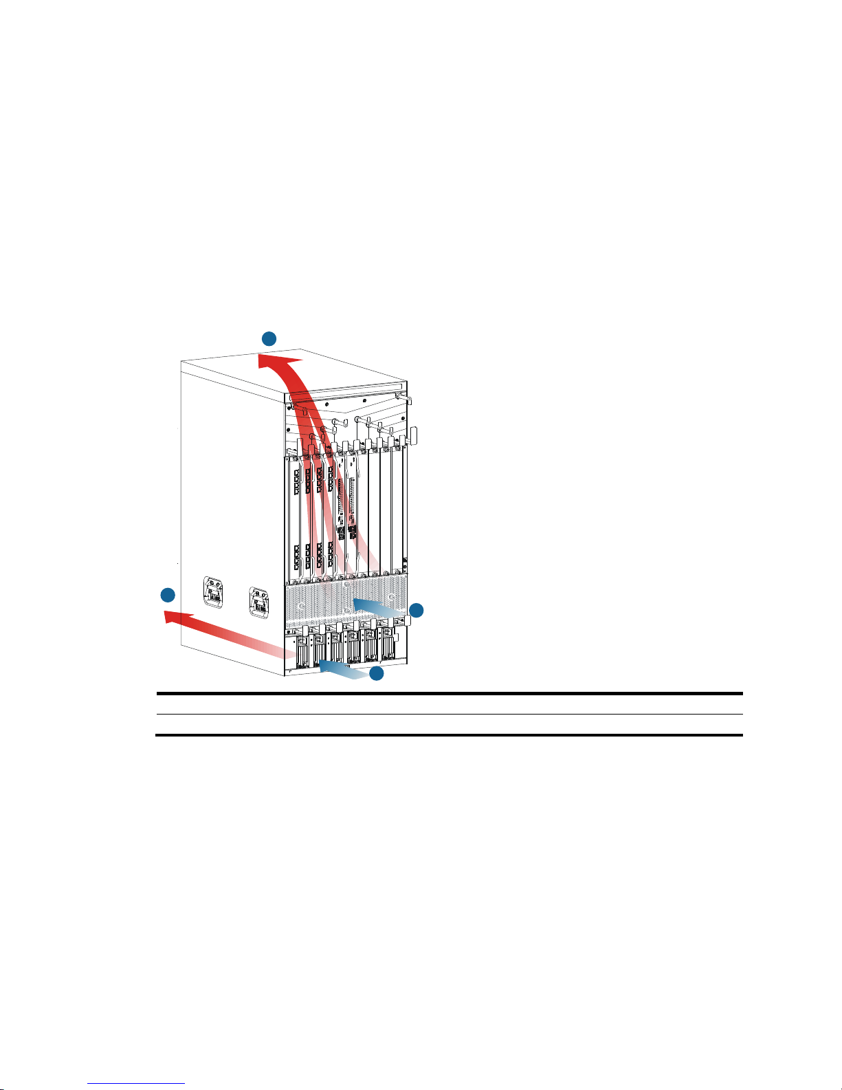
Figure 1 Airflow through the 10508-V chassis
(1) Power supply air intake vents (2) Power supply air exhaust vents
(3) Chassis air intake vents (4) Chassis air exhaust vents
2
4
1
3
Page 12
6
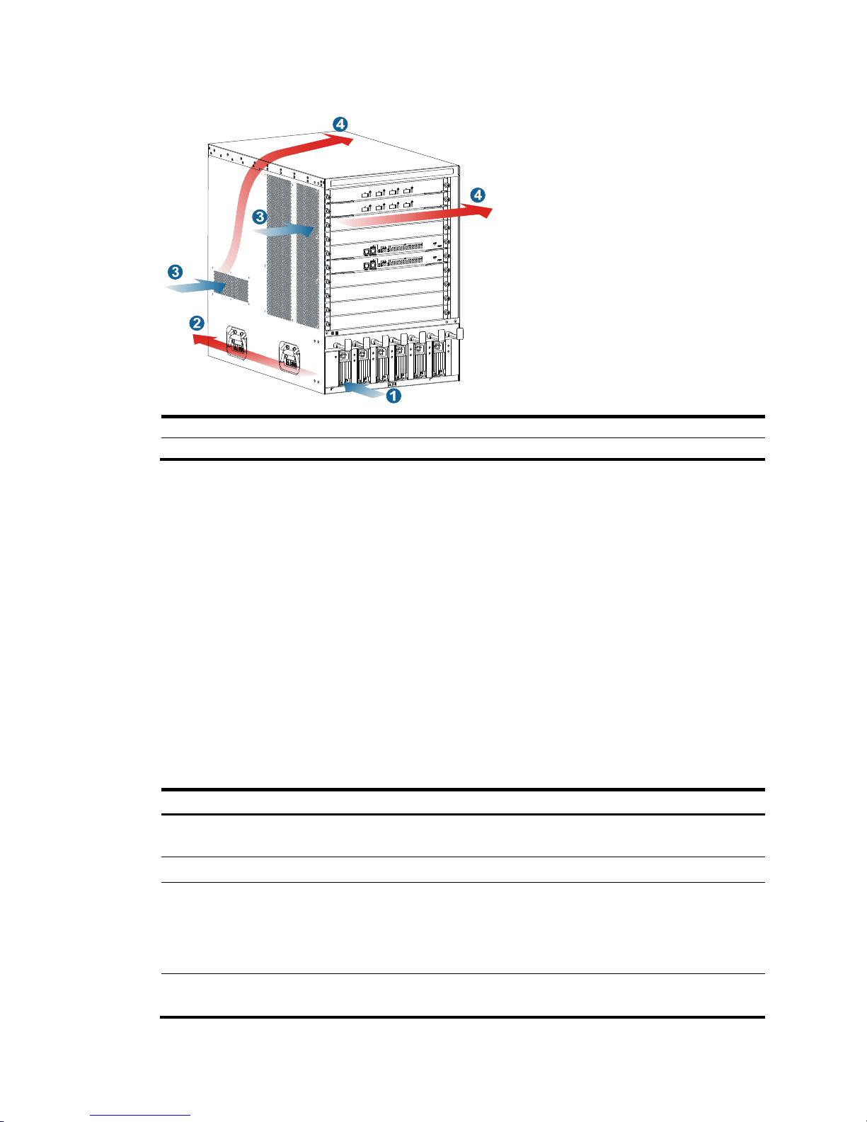
Figure 2 Airflow through other 10500 switch chassis
(1) Power supply air intake vents (2) Power supply air exhaust vents
(3) Chassis air intake vents (4) Chassis air exhaust vents
Space
For easy maintenance, follow these guidelines:
• A minimum of 10 cm (3.94 in) of clearance is reserved between the rack and walls or other devices.
• The equipment room is a minimum of 3 m (9.84 ft) high.
• Rack dimensions are sufficient for the chassis. For more information about chassis specifications,
see "Appendix A Chassis views and technical specifications."
Tools and equipment
Table 6 lists the tools and equipment that you might use during installation, and all of them are user
supplied.
Table 6 Tools and equipment list
Cate
gory
Tool
Measuring and marking tools
Long tape, ruler (of 1 meter, or 3.28 ft), gradienter, marker, chalk line, and
pencil
Drills Percussion drill, electric drill, and several auxiliary drill bits
Fastening tools
Flat-blade screwdriver P4-75 mm
Phillips screwdriver P1-100 mm, P2-150 mm, and P3-250 mm
Socket wrench M5
Socket wrench M6
Small tools
Needle-nose pliers, diagonal pliers, combination pliers, wire-stripping pliers,
crimping pliers, RJ-45 crimping pliers, file, and handsaw
Page 13

7
Category Tool
Auxiliary tools
ESD wrist strap, hair brush, tweezers, paper knife, hand bellows, electric iron,
solder wire, ladder, cable stripper, vacuum cleaner, crowbar, and rubber
hammer
Tools for fiber-optic cleaning Lint-free paper and optical fiber microscope
Equipment
Multimeter, 500 V Megohmmeter for measuring the insulation resistance, error
detector, optical power meter, and earth resistance tester
Page 14

8
Installing the switch
IMPORTANT:
Keep the packages of the switch and the components for future use.
Confirming installation preparations
Before you install the switch, verify that:
• You have read "Preparing for installation" car
efully and the installation site meets all the
requirements.
• If you are rack-mounting the switch, verify that the following conditions are met:
{ A 19-inch rack is ready for use. For how to install a rack, see the rack installation guide.
{ The rack is sturdy and securely grounded.
{ No debris exists inside or around the rack.
{ Choose a correct rack mounting position for the switch. Make sure the heaviest device is placed
at the bottom of the rack.
{ The total height of the switches to be installed is no higher than the available installation height
of the rack, and enough clearance is reserved for cable routing.
• If you are mounting the switch on a workbench, make sure the workbench is sturdy and securely
grounded.
• The switch is ready for installation and has been carried to a place near the installation site and
convenient for moving.
Installing the switch in a 19-inch rack
Attaching slide rails and cage nuts to the rack
Installing slide rails
If the rack has slide rails, skip this section.
Before you attach slide rails to the rack, verify that the following conditions are met:
• The slide rails can support the weight of the switch. For the weights of the 10500 switches, see
"Appendix A Chassis views and technical specifications."
HP recommen
ds that you order the HP X421 A-Series Chassis Universal 4-Post Rack Mounting Kit
(JC665A). For more information about the kit, see "Appendix B FRUs and compatibility matrixes."
• If y
ou install the switch in an enclosed cabinet, make sure the distance between the front rack posts
and the front door is a minimum of 100 mm (3.94 in) for installing cable management brackets,
and the distance between the front rack posts and the rear door is a minimum of 660 mm (25.98
in) for the chassis with cards installed.
Page 15
9
• To ensure rack stability, install the slide rails to the lowest possible position when installing a single
switch on the rack. To install multiple switches on the rack, mount the heaviest switch at the bottom
of the rack.
• Identify the chassis and slide rail positions for the switch. For the height and other specifications, see
"Appendix A Chassis views and technical specifications."
Slide rail installation varies by rack type. This section uses the slide rails in the HP rack mounting kit
(JC665A) as an example.
To install a slide rail:
1. Read the mark on the slide rail (see Table 7) to avoid
making a mistake.
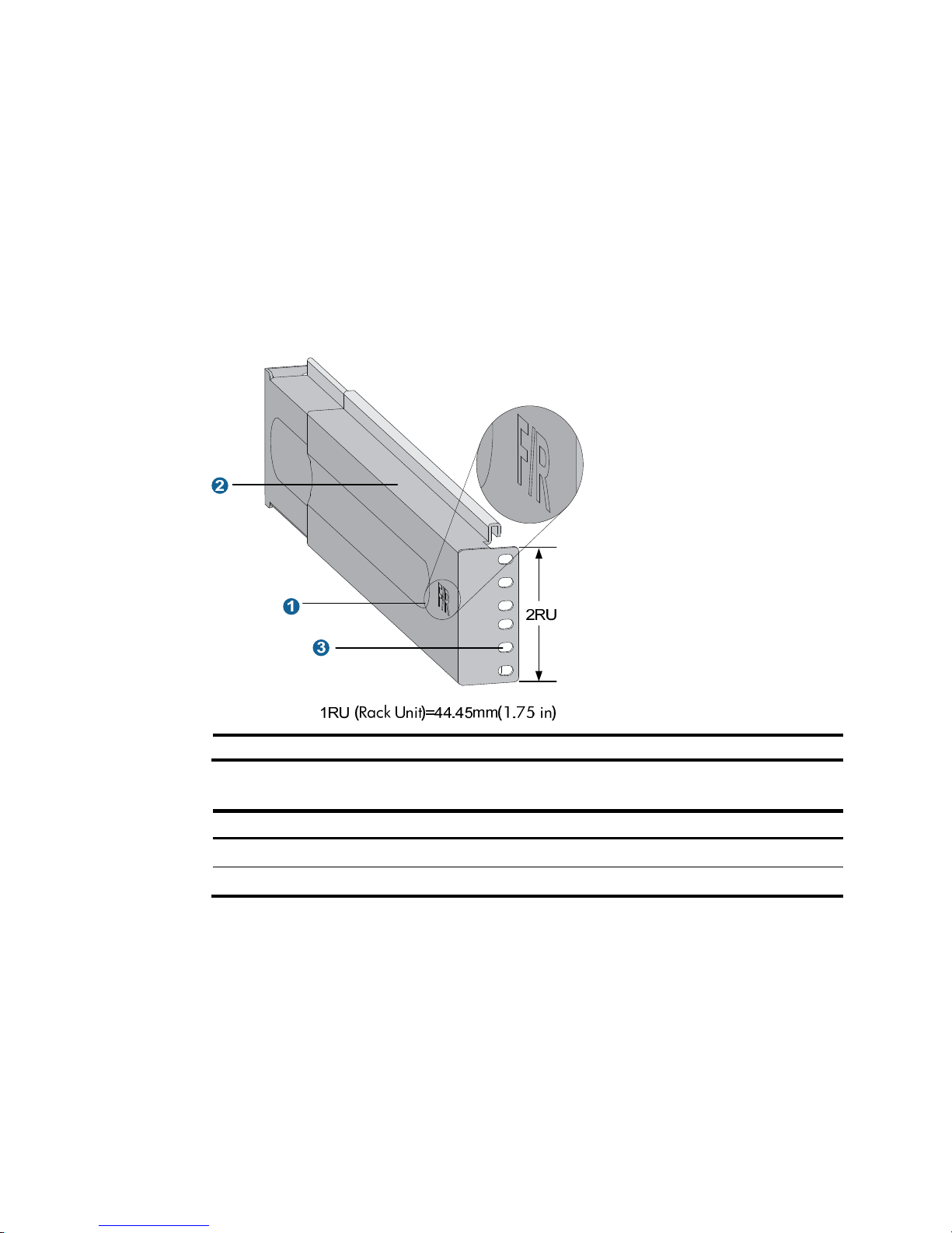
Figure 3 Right slide rail
(1) Mark (2) Guide rail (3) Installation hole
Table 7 Description for marks on the slide rails
Mar
k
Descri
p
tion
Remarks
F/L Front end of the left slide rail Mount this end to the front left rack post.
F/R Front end of the right slide rail Mount this end to the front right rack post.
2. Mark the position on the rack for installing the slide rail:
a. Make sure the bottom edge of the slide rail aligns with the middle of the narrower metal area
between holes, as shown in Figure 4.
b. E
ach rack post requires six screw s to attach the slide rail. Mark the uppermost square hole and
lowermost square hole for installation.
c. Mark the square holes at the same height on the other three rack posts.
Page 16
10
NOTE:
One rack unit has three holes, the middle of which is an auxiliary installation hole, and the other two
are standard installation holes. You can distinguish them by the space between each two holes. The
space between a standard installation hole and an auxiliary installation hole is wider than that
between two adjacent standard installation holes.
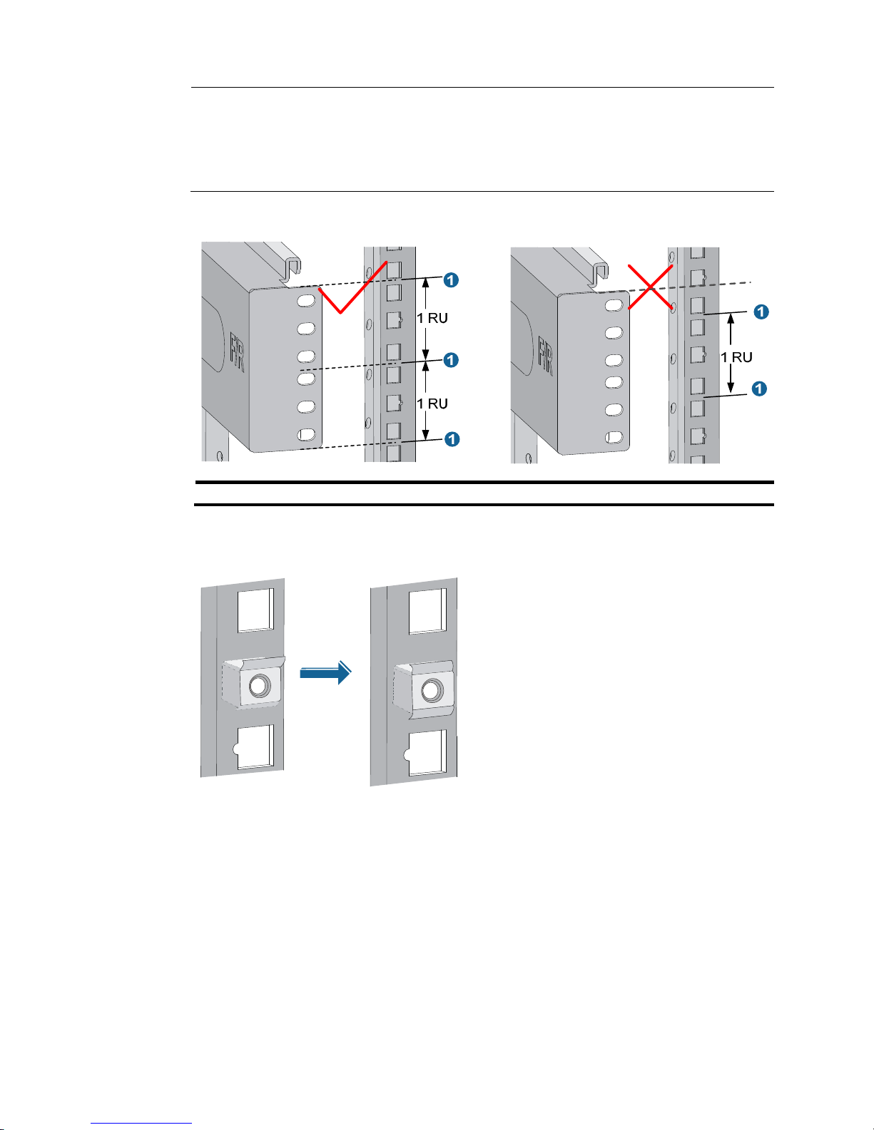
Figure 4 Locating the rack position for installing slide rails
(1) Middle of the narrower metal area between holes
3. Install six cage nuts in the square holes in each rack post, as shown in Figure 5.
Figure 5 Installing a cage nut
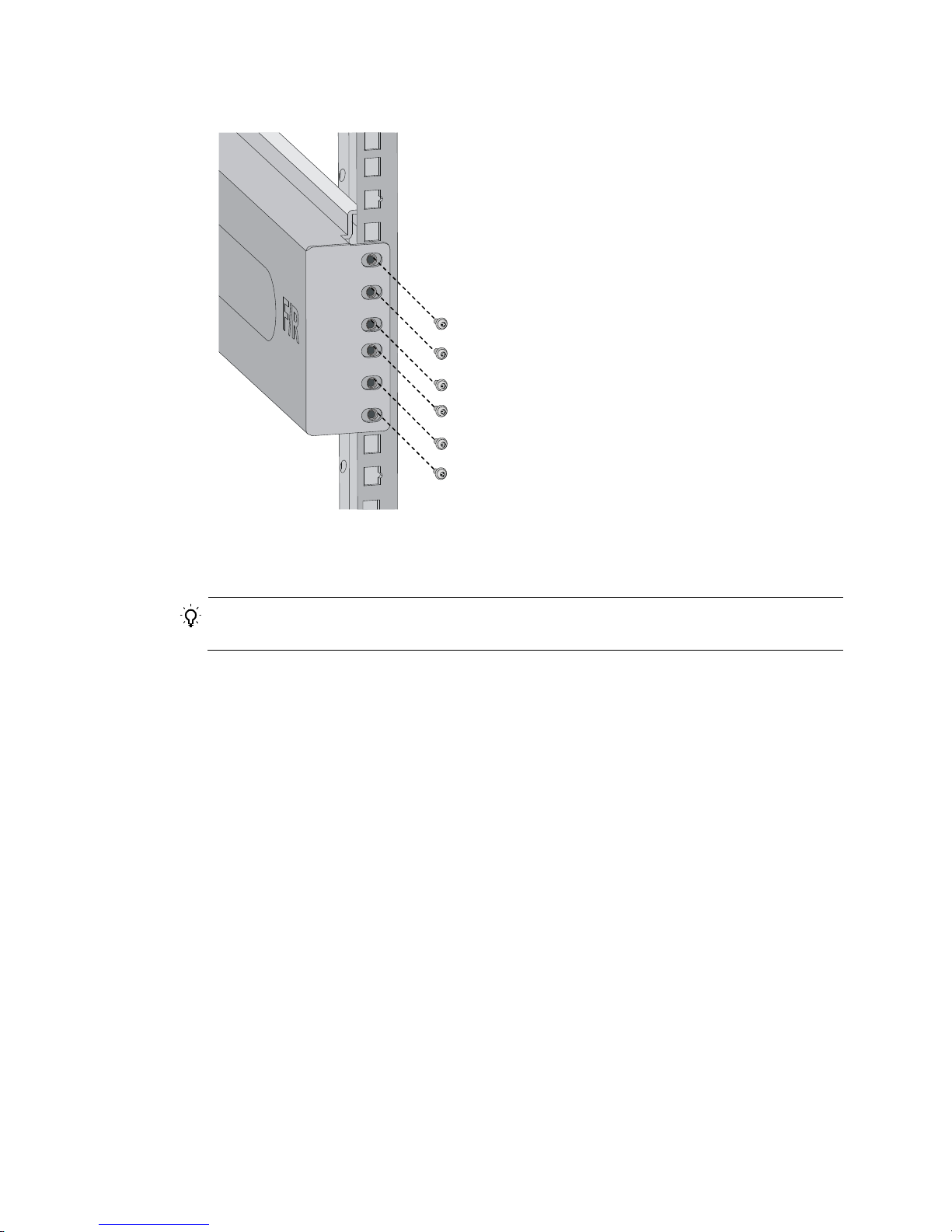
4. Align the installation holes on the front end of the slide rail with the cage nuts on the front rack post,
and attach them with screws, as shown in Figure 6.
Page 17
11
Figure 6 Attaching the slide rail to the cage nuts with screws
5. Keep the slide rail horizontally and adjust its length until the installation holes on the rear end of the
slide rail touch the cage nuts on the rear rack post. Then screw in screws and fasten.
TIP:
Install a screw in each mounting hole of the slide rail to ensure its weight bearing capacity.
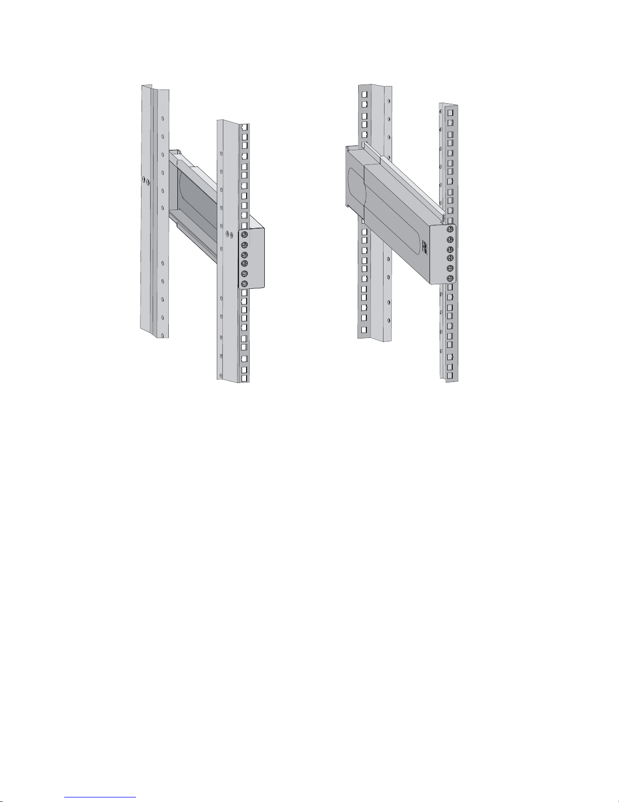
6. Repeat steps 4 and 5 to install the other slide rail. Make sure the two slide rails are at the same
height so the device can be placed on them horizontally.
Page 18
12
Figure 7 Installed slide rails
Installing cage nuts
To install cage nuts to the front square-holed brackets of the rack:
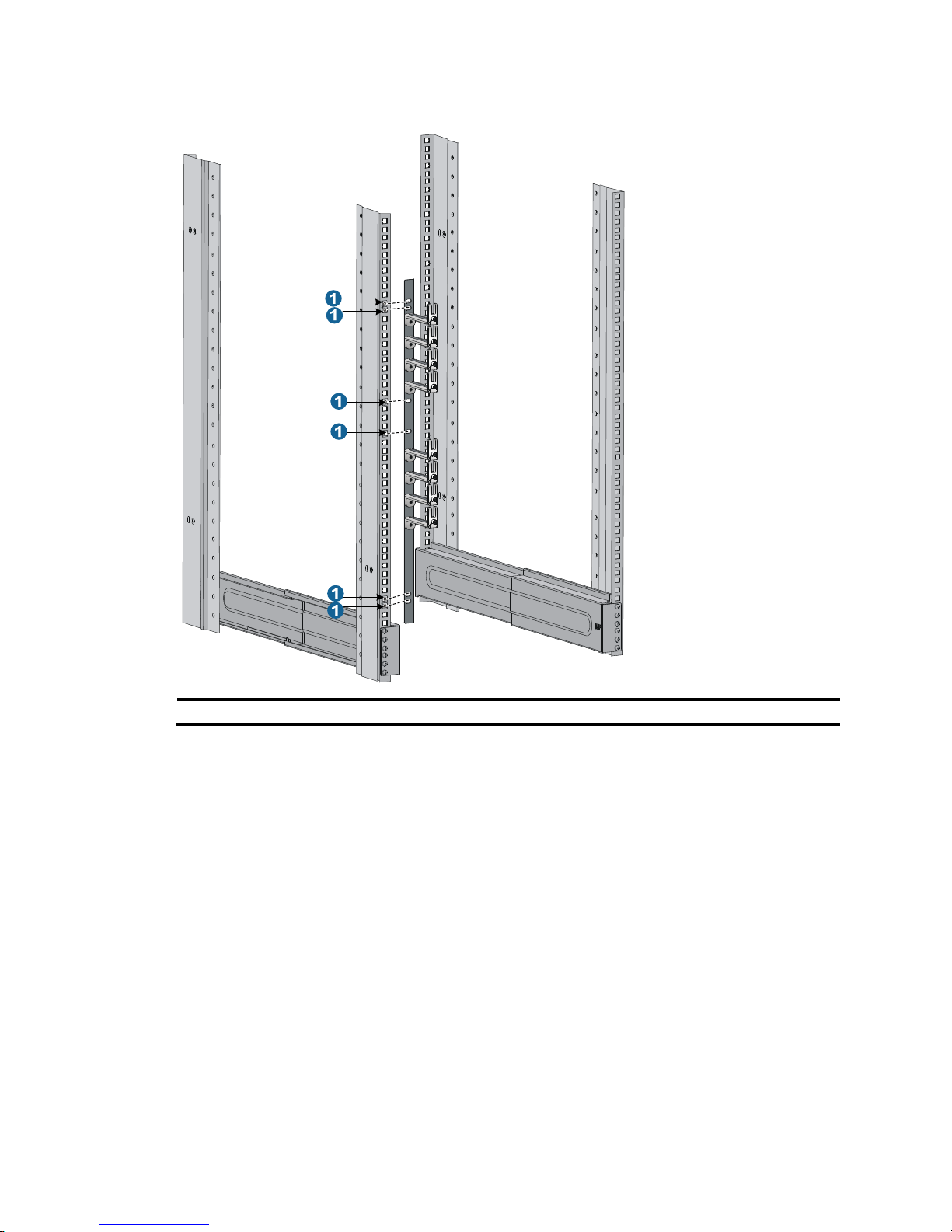
1. Determine the placement of the cage nuts, depending on holes in the mounting brackets and the
mounting position of the slide rails, as shown in Figure 8.
2. Install c
age nuts on the square holes on each rack post, as shown in Figure 5.
Page 19
13
Figure 8 Installing cage nuts (10508 as an example)
(1) Cage nuts
Installing mounting brackets and cable management brackets
Before installing the switch to the rack, install the cable management brackets and mounting brackets
shipped with the switch. Cable management brackets are used for securing and organizing signal
cables and power cords on the switch, and mounting brackets are used for attaching the chassis to the
rack.
Installing cable management brackets
You must install the signal cable management brackets separately for the 10508-V switch. All other
10500 switches come with the signal cable management brackets secured to the mounting brackets. In
this step, you only need to install the power cord management brackets for them.
• The 10508-V has two cable management brackets: the signal cable management brackets are
installed at the upper part of the switch, and the power cord management brackets are installed at
the lower part of the switch. They are installed in the same way. For more information, see Figure 9.
• T
he power cord management bracket installation procedure for the 10508 and 10512 is the same
as 10508-V.
Page 20
14
• The power cord management brackets of the 10504 have a slightly different structure, and installed
in a similar procedure. For more information, see Figure 10.
T
o install a cable management bracket:
1. Unpack the cable management brackets.
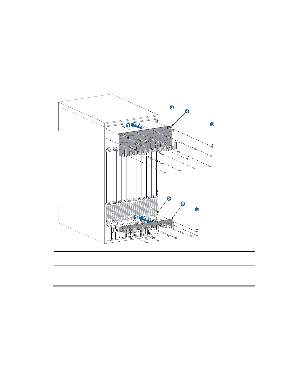
2. Attach the cable management bracket to the chassis, and align the screws with the mounting holes
on the chassis, as shown in Figure 9.
3. Fasten the s
crews.
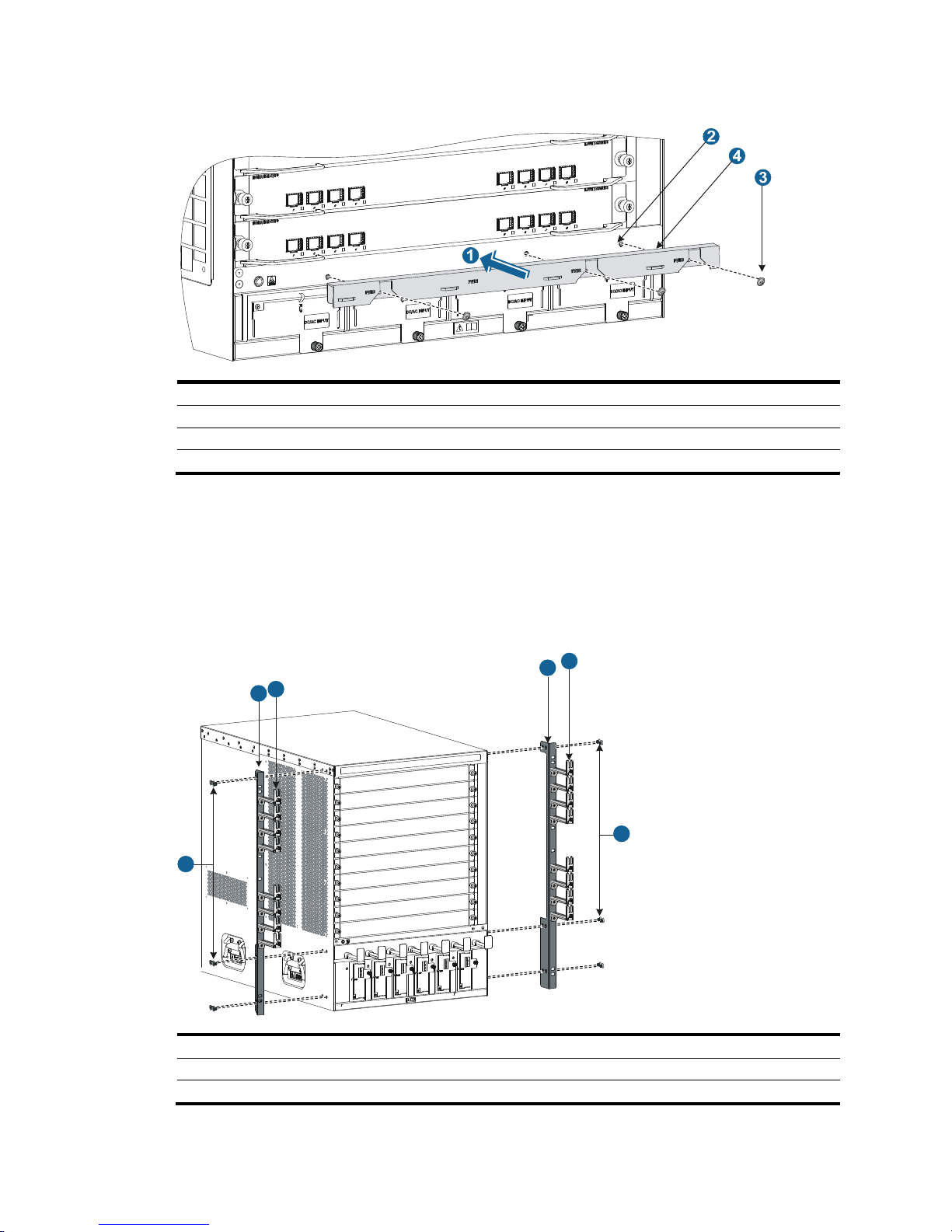
Figure 9 Attaching cable management brackets to a 10508-V
(1) Attach the cable management bracket to the chassis.
(2) Mounting holes for installing the cable management bracket.
(3) Screws for attaching the cable management bracket to the chassis.
(4) Signal cable management bracket (installed at the upper part of the chassis).
(5) Power cord management bracket (installed at the lower part of the chassis).
Page 21
15
Figure 10 Attaching cable management brackets to a 10504
(1) Attach the cable management bracket to the chassis.
(2) Mounting holes for installing the cable management bracket.
(3) Screws for attaching the cable management bracket to the chassis.
(4) Power cord management bracket (installed at the lower part of the chassis).
Attaching mounting brackets to the chassis
1. Identify the left mounting bracket (marked L) and the right mounting bracket (marked R) on the inner
surface of the mounting brackets.
2. Facing the chassis front, mount the left and right mounting brackets to the two sides of the chassis,
as shown in Figure 11.
Figure 11 Installing the
mounting brackets (10508)
(1) Screws for attaching the mounting brackets to the chassis
(2) Mounting brackets
(3) Signal cable management brackets
1
1
2
2
3
3
Page 22
16
Mounting the switch in the rack
CAUTION:
• Do not hold the handle of the fan tray, power supply, or the back cover of the chassis, or the air vents of
chassis. Any attempt to carry the switch with these parts might cause equipment dama
g
e or even bodily
injury.
• After placing the switch on the slide rails, do not let go right away because this might tip the switch,
damage the switch, or cause bodily injury.
To mount the switch in the rack:
1. Move the chassis to face the rear of the chassis towards the front of the rack.
2. Use a minimum of two people to lift the switch by using the handles or supporting the bottom of the
chassis until the bottom of the switch is a little higher than the slide rails on the rack.
HP recommends that you use a mechanical lift for moving your switch.
3. Place the switch on the slide rails and slide the switch along the slide rails until the mounting
brackets on the switch touch the front rack posts, as shown by callout 1 in Figure 12.
4. Attach the ch
assis to the rack with mounting screws.
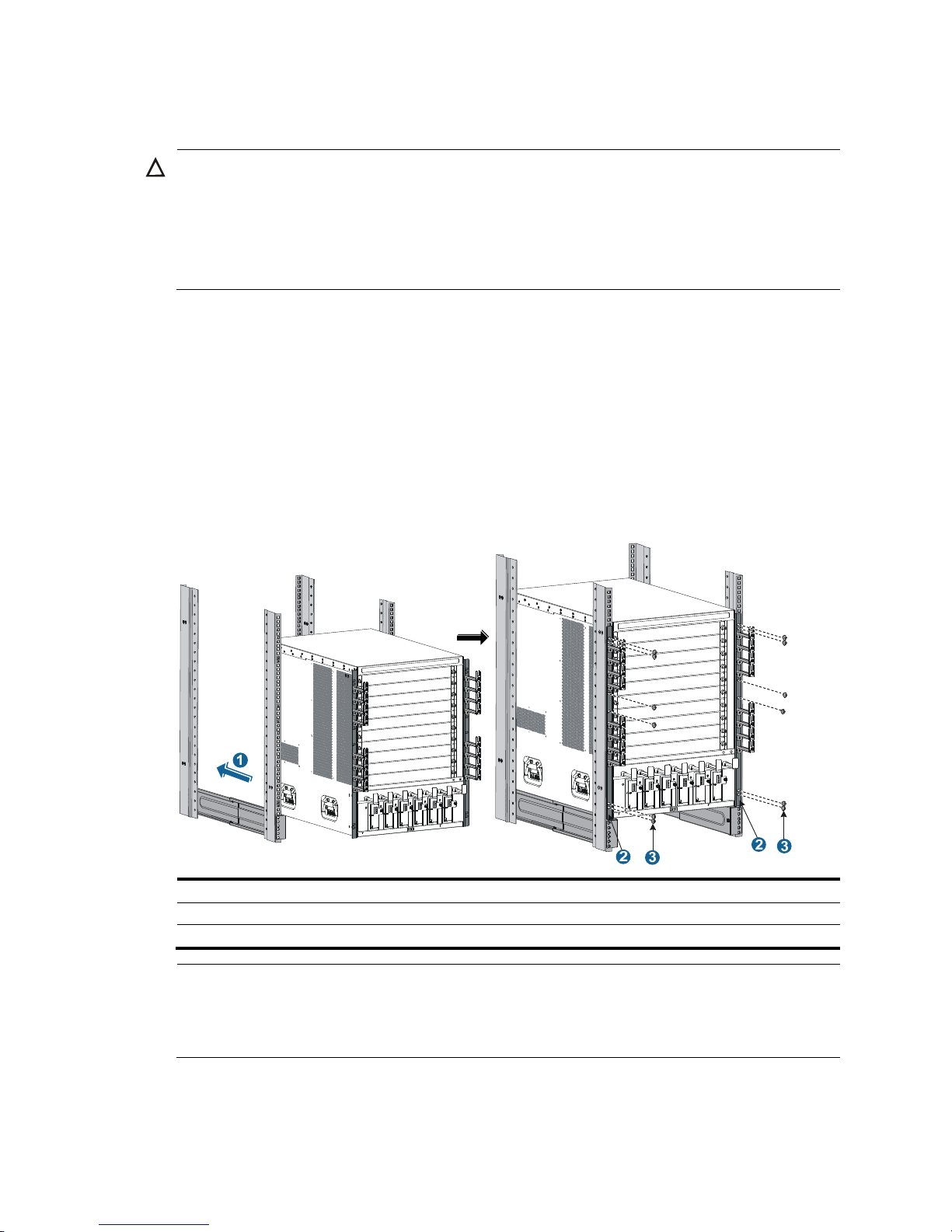
Figure 12 Installing the chassis in the rack (10508)
(1) Slide the chassis into the rack
(2) Mounting brackets
(3) Screws for attaching the mounting brackets to the rack
NOTE:
If the mounting holes in the mounting brackets cannot align with the cage nuts on the rack, verify that the
bottom edge of the slide rail aligns with the middle of the narrower metal area between holes and that the
cage nuts are installed in the correct holes.
Page 23
17
Mounting the switch on a workbench or floor
You can install the switch on a clean, sturdy workbench or on the floor.
Installation preparation
Before you mount the switch on a workbench or on the floor:
• Position the installation holes and drill holes. Make sure the holes are exact in diameter and depth
for the anchors to operate correctly.
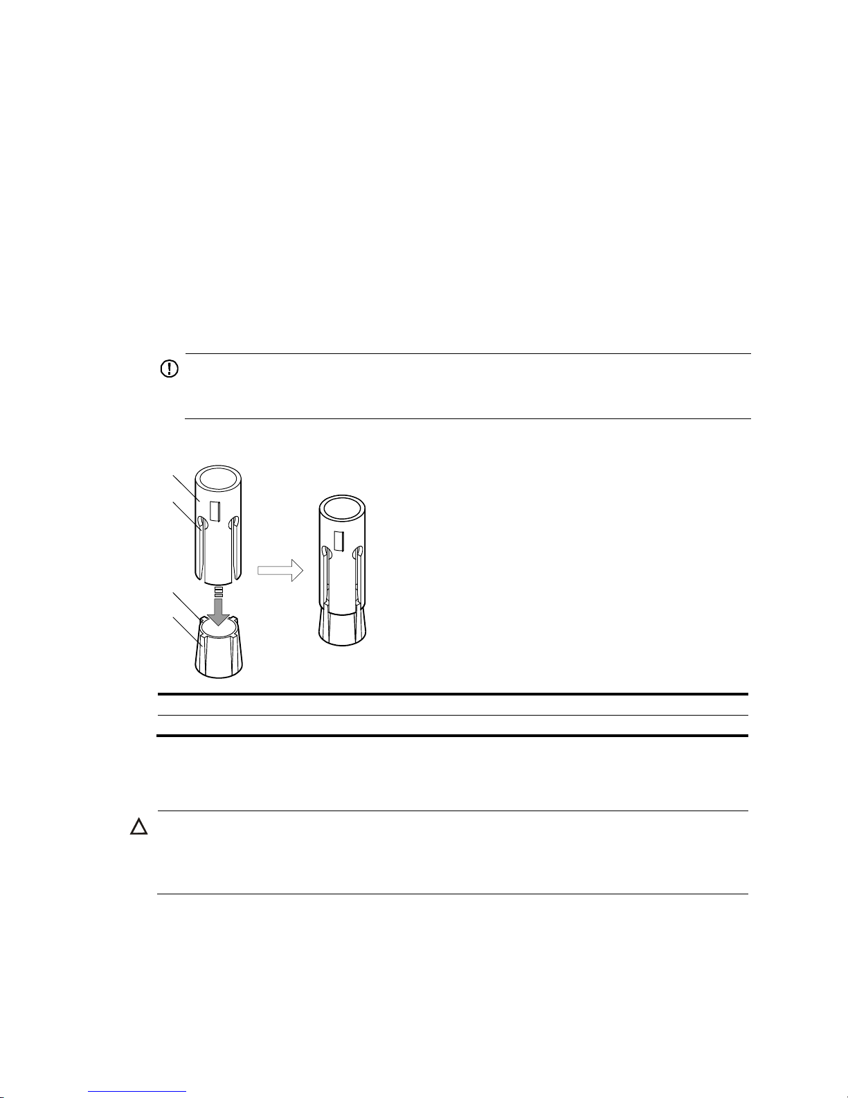
• Remove the shank and plug from a wall anchor, insert the spade-shaped wedges into the grooves
on the shank, put them into an installation hole, and hammer the shank into the ground. See Figure
13 .
IMPORTANT:
Before you hammer the shank to the workbench or floor, insert the spade-shaped wedges into the
grooves on the shank. Otherwise, the wall anchor cannot be installed correctly.
Figure 13 Installing the shank to the plug
(1) Shank (2) Groove
(3) Plug (4) Spade-shaped wedge
Installation procedures
CAUTION:
Do not use the fan tray handles, power supply handles, chassis air vents, or handle of chassis back cover
for moving the chassis. These parts are not designed for weight support. Any attempt to carry the chassis
w
ith these parts might cause equipment damage or even bodily injury.
This task requires a minimum of two people. HP recommends that you use a mechanical lift to move the
chassis.
To mount the switch on a workbench or floor:
1
2
3
4
Page 24
18
1. Hold the handles on the chassis or support the chassis bottom and steadily move the chassis to the
workbench or floor.
2. Gently put the chassis on the workbench or floor.
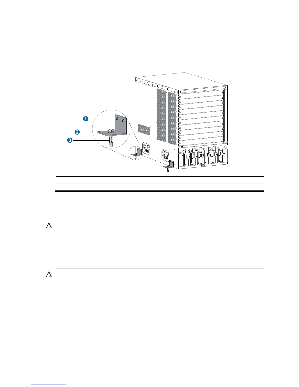
3. Attach the L-shaped brackets to the workbench or floor with wall anchors.
Figure 14 Attaching L-shaped brackets with wall anchors
(1) Fastening screw
(2) L-shaped bracket
(3) Wall anchor
Grounding the switch
CAUTION:
Before using the switch, connect the grounding cable correctly to guarantee lightning protection and
anti-interference of the switch.
Grounding the switch with a grounding strip
CAUTION:
• Use the supplied grounding cable (yellow-green grounding cable).
• Connect the
g
rounding cable to the earthing system in the equipment room. Do not connect it to a fire
main or lightning rod.
If a grounding strip is available at the installation site, connect the grounding cable through the
grounding strip.
To connect the grounding cable:
1. Unpack the grounding cable.
The grounding cable provided with the switch is compliant with the NEBS standards.
Page 25
19
2. Remove the grounding screws from the grounding holes at the rear of the chassis, as shown by
callout 2 in Figure 15.
3. Fasten the gr
ounding screws, which are attached with the dual-hole terminals of the grounding
cable, into the grounding holes of the chassis.
4. Connect the ring terminal of the grounding cable to the grounding post of the grounding strip, and
fasten the grounding cable to the grounding strip with the hex nut.
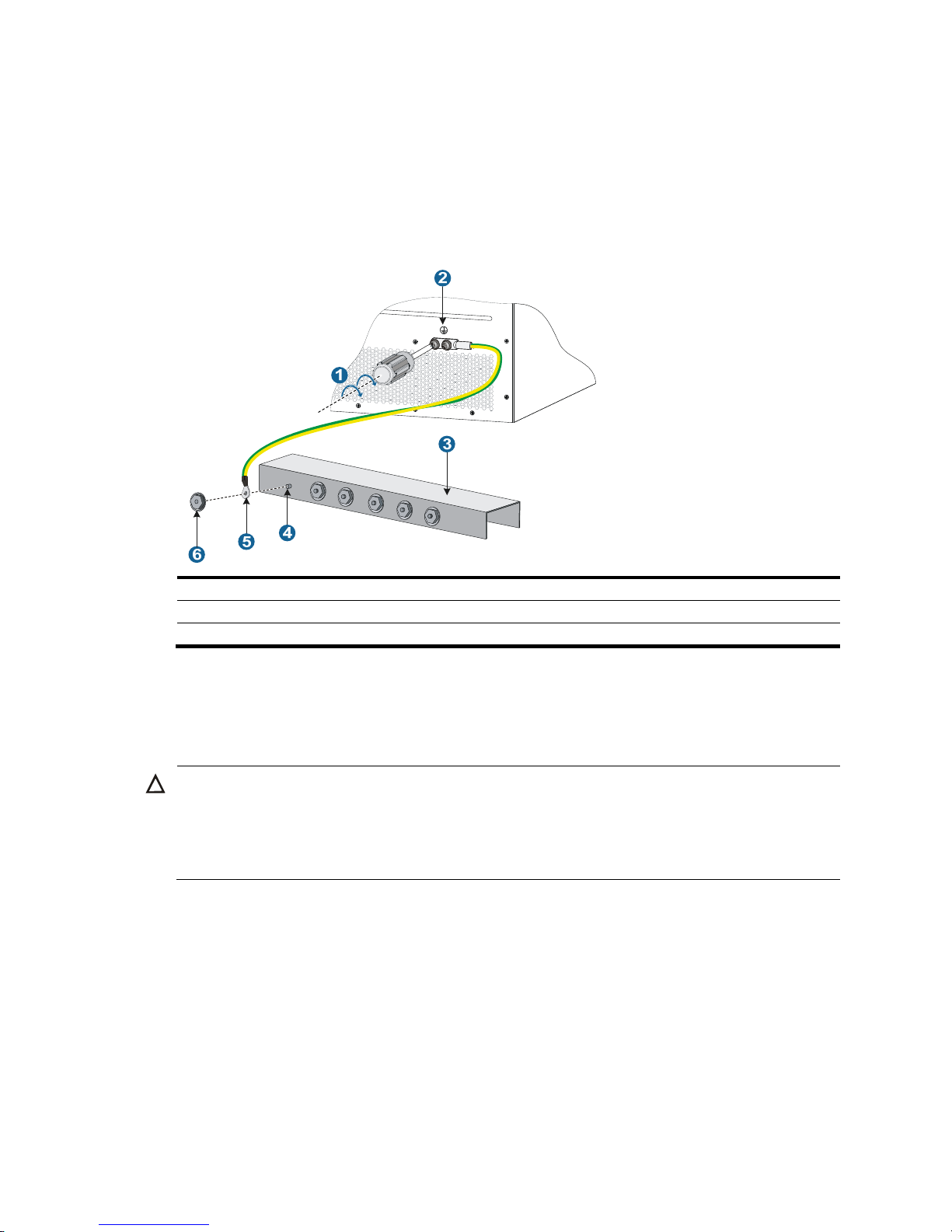
Figure 15 Connecting the grounding cable to a grounding strip
(1) Attach the grounding screws with dual-hole terminals to the grounding holes
(2) Grounding sign
(3) Grounding strip
(4) Grounding post
(5) Ring terminal (6) Hex nut
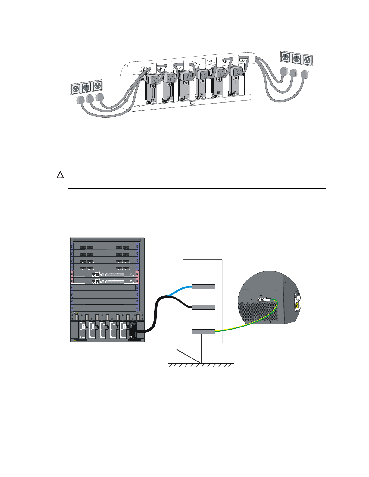
Grounding the switch through the PE wire of an AC power
supply
CAUTION:
Make sure the AC power supply uses a three-wire cable with a protection wire, and the PE wire of the AC
power supply is reliably grounded at the power distribution room or AC power supply transformer side.
In addition, make sure the PE connector on the switch is well connected to the PE wire of the AC power
supply.
If the switch is AC powered and no grounding strip is available at the installation site, you can ground
the switch through the PE wire of the AC power supply, as shown in Figure 16.
Page 26
20
Figure 16 Grounding the switch through the PE wire of the AC power supply
Grounding the switch through the RTN wire of a DC power
supply
CAUTION:
Make sure the RTN wire is reliably grounded from the DC egress of the DC power cabinet.
If the switch is powered by a –48 VDC power supply and no grounding strip is available at the
installation site, you can ground the switch through the return (RTN) wire of the DC power supply, as
shown in Figure 17.
Figure 17 Grounding the switch through the RTN wi
re of the DC power supply
DC power
box
–48V strip
RTN strip
PGND strip
Page 27

21
Installing FRUs
There is no required order for installing FRUs. HP recommends that you connect power cords after
installing all required FRUs.
TIP:
Keep the chassis and component packages for future use.
Attaching an ESD wrist strap
The switch provides an ESD wrist strap. To minimize ESD damage to electronic components, wear the
ESD wrist strap and make sure it is reliably grounded when installing modules.
To use an ESD wrist strap:
1. Make sure the switch is reliably grounded. For how to ground your switch, see "Installing the
swit
ch."
2. Put on the wrist strap.
3. Tighten the wrist strap to keep good skin contact. Make sure the resistance reading between your
body and the ground is between 1 and 10 megohms.
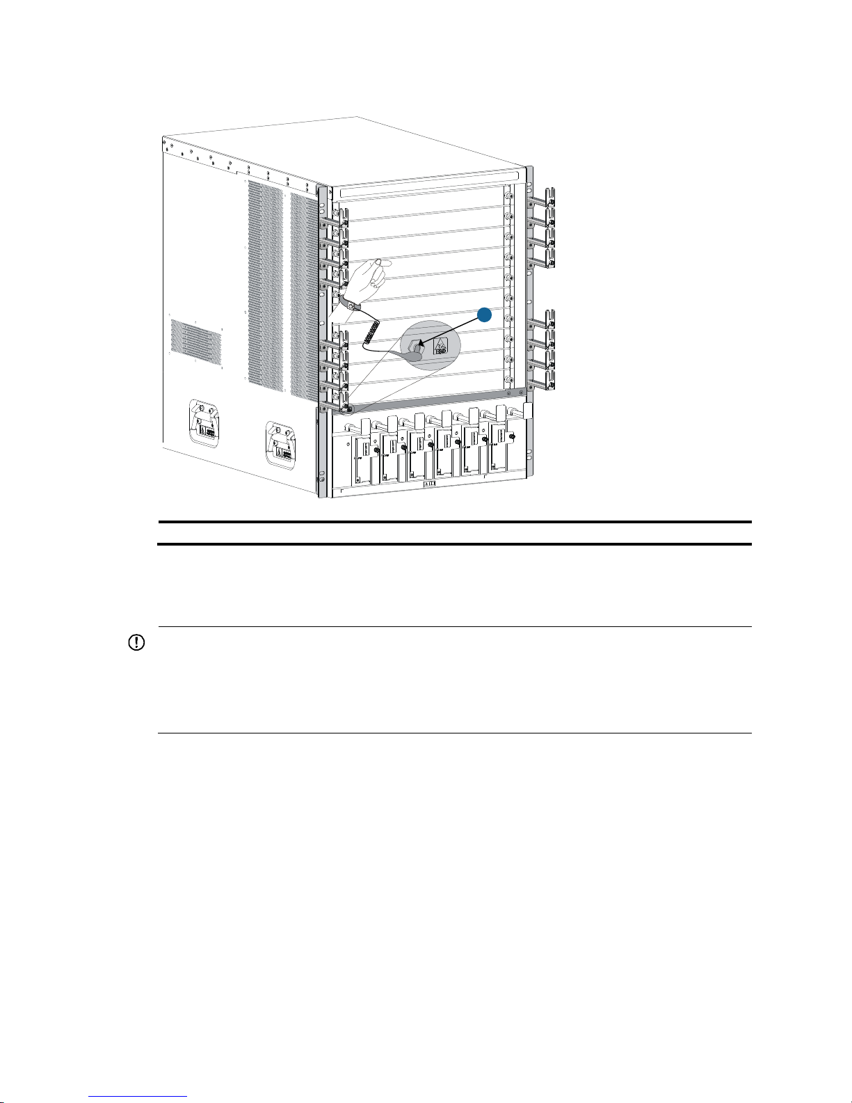
4. As shown in Figure 18, insert the ESD wrist strap into the ESD socket
on the switch chassis, or
attach it to the grounding screw of the chassis with an alligator clip.
Page 28
22
Figure 18 Attaching an ESD wrist strap (on a 10508)
(1) ESD socket (having an ESD mark)
Installing MPUs/LPUs/switching fabric modules
IMPORTANT:
• Before installing a card to the chassis, make sure the connectors on the card are not broken or blocked
to avoid damaging the backplane.
• To ensure good ventilation, install a blank filler panel over an empty MPU, LPU, or switching fabric
module slot. MPU slots use the same type of blank filler panels as LPU slots.
The installation procedures for MPUs, LPUs, and switching fabric modules are the same. Unless otherwise
stated, MPUs, LPUs, and switching fabric modules are collectively referred to as "cards" in this document.
These cards are either horizontally oriented or vertically oriented. When installing a card in a horizontal
slot, make sure its PCB faces up. When installing a card in a vertical slot, make sure its PCB faces left.
This section uses a horizontally oriented card as an example.
To install a horizontally oriented card:
1. Wear an ESD wrist strap, and make sure it makes good skin contact and is reliably grounded. For
more information, see "Attaching an ESD wrist strap."
2. As sh
own by callout 1 in Figure 19, remov
e the blank filler panel from the slot. Keep the blank filler
panel for future use.
Some card slots do not have a blank filler panel. The figures in this section are for illustration only.
1
Page 29
23
3. As shown by callout 2 in Figure 19, hold the card by the front panel with one hand and support
the card bottom with the other. Slide the card steadily into the slot along the guide rails.
4. When most part of the card is inserted in the slot, press the ejector levers on the card outward.
5. Push the card until the positioning pin on card touches the hole on the chassis.
6. As shown by callout 3 in Figure 19, pres
s the ejector levers inward until the ejector levers touch the
panel tightly and the card seats into the backplane
7. As shown by callout 4 in Figure 19, fasten the c
aptive screws on the card.
8. When the switch is powered on, verify the running status of the card.
You can verify the running status of a card by referring to the card status LED (SLOT) on the MPU
of the switch. If the RUN LED blinks, the card in the slot operates correctly. For more information
about card status LED (SLOT), see "Appendix C LEDs."
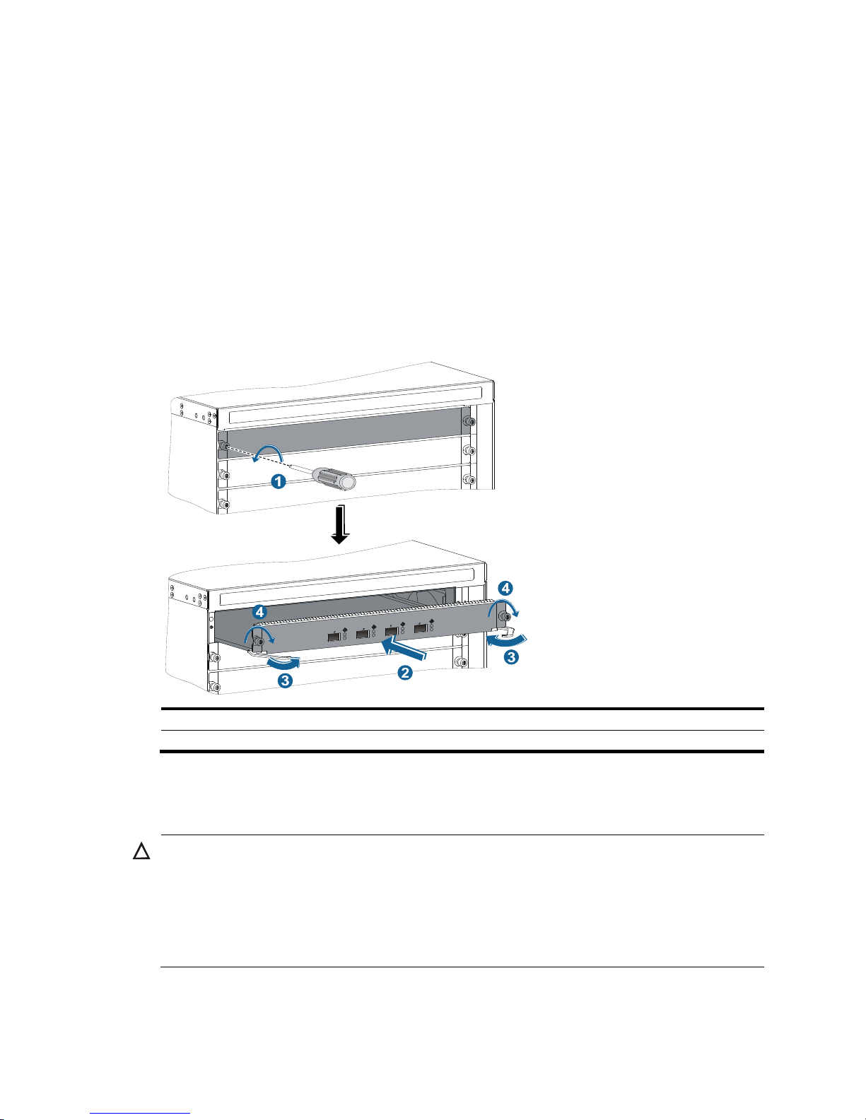
Figure 19 Installing a ca
rd
(1) Loosen the captive screws (2) Insert the card into the slot
(3) Press the ejector levers inward (4) Fasten the captive screws
Installing a power supply
CAUTION:
• Provide a circuit breaker for each power supply and make sure the circuit breaker is off before
installation.
• Do not install power supplies of different models on the same switch.
• To avoid power supply damage or bodily injury, support the bottom of a power supply instead of
holding its handle for power supply movement.
The switch uses N + 1 or N + N power redundancy and supports AC or DC power input.
Page 30

24
The power supply slots are horizontal on a 10504 switch and vertical on a 10508, 10508-V, or 10512
switch.
Strictly follow the order shown in Figure 20 to a
void security hazards.
Figure 20 Power supply installation flow
AC and DC power supplies are installed in the same way. This section uses an AC power supply as an
example. For information about AC and DC power supplies, see HP 10500 2500W AC Power Supply
User Guide and HP 10500 2400W DC Power Supply User Guide.
Some power supply slots do not have blank panels. The figures in this section are for illustration only.
To install the power supply:
1. Wear an ESD wrist strap and make sure it makes good skin contact and is reliably grounded. For
more information, see "Attaching an ESD wrist strap."
2. Use a Phillip
s screwdriver to loosen the captive screws on the blank filler panel (if any) to remove
the blank filler panel.
3. Unpack the power supply.
4. Follow the installation graph printed on the blank filler panel of the power supply to install the
power supply in a correct direction:
a. Grasp the handle of the module with one hand and support the module bottom with the other.
b. Push the power supply along the guide rails into the slot until it has firm contact with the slot.
For vertical slot installation, see callout 1 in Figure 21. For horizontal slot installation, see
callo
ut 1 in Figure 22.
5. Press the han
dle inward until the handle seats into the slot.
6. As shown by callout 2 in Figure 21, us
e a Phillips screwdriver to fasten the captive screw on the
handle to attach the power supply.
Page 31

25
Figure 21 Installing an AC power supply in a vertical slot
(1) Install the power supply to the chassis. (2) Fasten the captive screw.
1
2
Page 32

26
Figure 22 Installing an AC power supply in a horizontal slot
(1) Install the power supply to the chassis.
Connecting the power cord
Connecting an AC power cord
W
ARNING!
Before connecting the power cord, make sure the circuit breaker on the power cord is switched off.
To connect an AC power cord:
1. Connect the power cord to the power receptacle of the power supply.
2. Use a cable tie to secure the power cord to the cable management bracket.
{ Figure 23 shows how to connect the power cord for a vertical slot switch (10508, 10508-V, and
10512) .
{ Figure 24 shows how to connect the power cord for a horizontal slot switch (10504).
3. Connect the other end of the power cord to the AC power receptacle of the power source and
switch on the circuit breaker.
4. Verify the power supply input status LED.
If the LED is on, the power cord is correctly connected. For description of power supply status LEDs,
see "Appendix C LEDs."
Page 33

27
Figure 23 Securing the power cord (vertical slot)
Figure 24 Securing the power cord (horizontal slot)
Connecting a DC power cord
WA
RNING!
• Make sure each power cord has a separate circuit breaker.
• Before you connect the power cord, make sure the circuit breaker on the power cord is switched off.
• Make sure the circuit breaker at the power input end is off when you connect the DC power cord to the
terminals on the power source.
To connect a DC power cord:
1. Connect the power cord to the power receptacle of the power supply.
2. Fasten the screw to secure the power cord.
Page 34

28
Figure 25 Connecting the power cord (vertical slot)
(1) Insert the power cord plug into the power supply.
(2) Fasten the screw.
3. (Optional.) Use a cable tie to secure the power cord to the cable management bracket. For more
information, see Figure 23 and Figure 24.
4. Conne
ct one end of the blue DC power cord marked –48V to the negative terminal (–48V) on the
power source and the RTN end of the black DC power cord to the positive terminal (RTN).
Installing a transceiver module (optional)
CAUTION:
• To avoid component damage, read this section carefully before installing a transceiver module.
• Do not remove the protection cover from a transceiver module before connecting an optical fiber.
• Remove the optical fiber, if any, from a transceiver module before installing it.
The transceiver modules available for the switch include SFP, SFP+, XFP, QSFP+, and CFP.
Installing an XFP/SFP+/SFP/QSFP+ module
1. Wear an ESD wrist strap and make sure it makes good skin contact and is reliably grounded. For
more information, see "Attaching an ESD wrist strap."
2. Unpac
k the module. Do not touch the golden plating of the module.
3. Pivot the clasp of the module up. Holding the module, gently push the module into the slot until it
has firm contact with the slot (when the top and bottom spring tabs catch in the slot), as shown
in Figure 26.
{ For a QSFP+ module that uses a plastic pull latch, skip this step. QSFP+ modules use either a
metal or plastic pull latch. They are installed in the same way except that you must pivot the
clasp up for the module that uses a metal pull latch.
{ For an SFP+ module, press the module down against the upward force of the bottom spring tab
so you can push the module straight into the port.
{ If you cannot hold the module by its two sides because of high module density, press the module
on its head end to push it in.
Page 35

29
4. Connect the fiber to the module. For the installation procedure, see "Connecting your switch to the
network."
Figure 26 Installing an XFP/SFP+/SFP/QSFP+ mo
dule
Installing a CFP module
1. Wear an ESD wrist strap and make sure it makes good skin contact and is reliably grounded. For
more information, see "Attaching an ESD wrist strap."
2. Unpack the CFP module. Do not touch the golden plati
ng of the module.
3. Holding both sides of the module, gently push the module into the slot until it has firm contact with
the slot. See Figure 27.
4. Fasten the
captive screws.
5. Connect the fiber to the module. For the installation procedure, see "Connecting your switch to the
network."
Figure 27 Installing a CF
P module
(1) Gently push the module into the slot.
(2) Fasten the captive screws.
Connecting an SFP+/QSFP+/QSFP+ to SFP+ cable
Use SFP+ cables to connect SFP+ ports, QSFP+ cables to connect QSFP+ ports, and QSFP+ to SFP+
cables to connect QSFP+ and SFP+ ports. All these cables are hot swappable.
To connect an SFP+, QSFP+, or QSFP+ to SFP+ cable:
Page 36

30
1. Wear an ESD wrist strap and make sure it makes good skin contact and is reliably grounded. For
more information, see "Attaching an ESD wrist strap."
2. Unpac
k the cable.
3. Connect the cable connector to the port. Make sure the cable connector is the right side up.
The bend radius of the cable must be a minimum of eight times the cable diameter.
Page 37
31
Setting up an IRF fabric
You can use HP IRF technology to connect and virtualize the switches into a large virtual switch called an
"IRF fabric" for flattened network topology, high availability, scalability, and manageability. For more
information about IRF, see HP 10500 Switch Series IRF Configuration Guide.
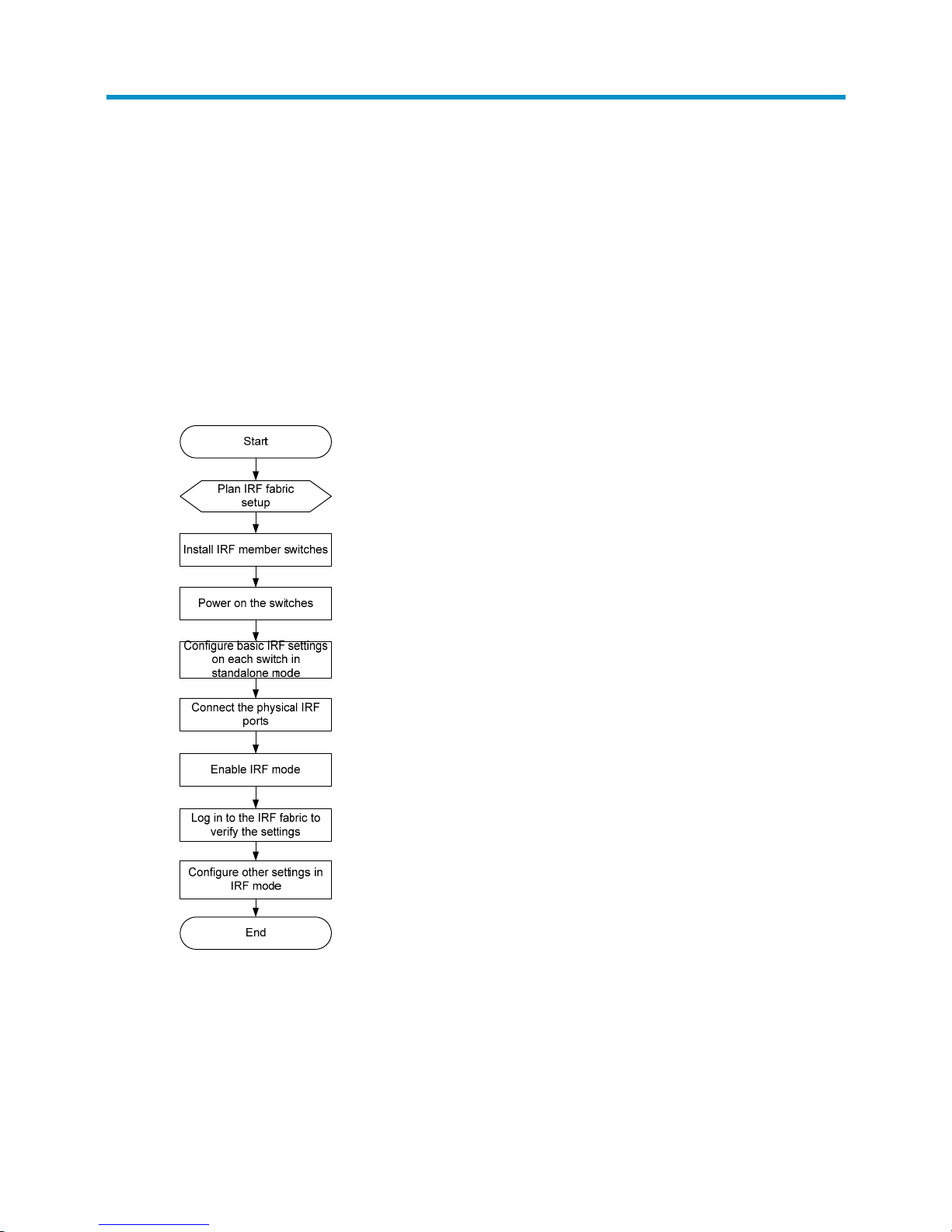
IRF fabric setup flowchart
The setup flow is shown in Figure 28. For the actual procedure, see HP 10500 Switch Series IRF
Configuration Guide for the software release you are using.
Figure 28 IRF fabric setup flowchart
To set up an IRF fabric:
Page 38

32
Step Description
1. Plan IRF fabric setup.
Plan the installation site and IRF fabric setup parameters:
• Planning IRF fabric size and the installation site
• Identifying the master switch and planning IRF member IDs
• Planning IRF topology and connections
• Identifying physical IRF ports on the member switches
2. Install IRF member
switches.
See "Installing the switch."
3. Power on the switches.
N/A
4. Configure basic IRF
settings on each switch
in standalone mode.
See HP 10500 Switch Series IRF Configuration Guide.
5. Connect the physical
IRF ports.
Connect physical IRF ports on switches.
6. Enable IRF mode.
See HP 10500 Switch Series IRF Configuration Guide.
7. Verify the IRF settings.
Log in to the IRF fabric at any member switch and verify that you can configure
all member switches as if they were one node.
8. Configure other
settings in IRF mode.
See HP 10500 Switch Series IRF Configuration Guide.
Planning IRF fabric setup
This section describes issues that an IRF fabric setup plan must cover.
Planning IRF fabric size and the installation site
Plan IRF fabric size and the installation site, using the following procedure:
1. Use HP 10500 Switch Series IRF Configuration Guide as a reference to identify the number of
member switches that your system software version supports for an IRF fabric.
All member switches must use the same system software version.
2. Choose switch models for your network.
The member switches in a 10500 IRF fabric must be the same model.
3. Select LPUs that can provide 10-GE/40-GE/100-GE ports.
The switches require 10-GE/40-GE/100-GE ports for IRF connection. For more information about
LPUs, see "Appendix B FRUs and compatibility matrixes."
4. Selec
t XFP/SFP+/QSFP+/CFP transceiver modules and fibers for long-haul IRF connection, or
select SFP+/QSFP+/QSFP+ to SFP+ cables for short-haul IRF connection. Select 10GBASE-T
twisted-pair cables for short-haul IRF connection.
For more information about transceiver modules and cables, see "Appendix B FRUs and
compatibility matrixes."
5. Plan the installation site.
Page 39

33
Identifying the master switch and planning IRF member IDs
Determine which switch you want to use as the master for managing all member switches in the IRF
fabric.
An IRF fabric has only one master switch. You configure and manage all member switches in the IRF
fabric at the CLI of the master. IRF member switches will automatically elect a master. You can affect the
election result by assigning a high member priority to the intended master switch. For more information
about master election, see HP 10500 Switch Series IRF Configuration Guide.
Prepare an IRF member ID assignment scheme. An IRF fabric uses member IDs to uniquely identify and
manage its members, and you must assign each IRF member switch a unique member ID.
Planning IRF topology and connections
Connect the IRF member switches through IRF ports, the logical interfaces for the connections between
IRF member switches. Each IRF member switch has two IRF ports: IRF-port 1 and IRF-port 2. To use an IRF
port, you must bind a minimum of one physical port to it.
When connecting two neighboring IRF member switches, you must connect the physical ports of IRF-port
1 on one switch to the physical ports of IRF-port 2 on the other switch.
A two-member IRF fabric must use the daisy chain topology.
If the system software version you are using supports more than two IRF members, you can create an IRF
fabric that comprises more than two members in daisy chain topology or more reliable ring topology. In
ring topology, the failure of one IRF link does not cause the IRF fabric to split as in daisy chain topology.
Instead, the IRF fabric changes to a daisy chain topology without interrupting network services.
Identifying physical IRF ports on the member switches
Identify the physical IRF ports on the member switches according to your topology and connection
scheme.
On the switch, only 10-GE/40-GE/100-GE ports can be used for IRF connection.
The switch supports multi-card link aggregation for IRF ports. You can bind up to eight physical ports to
one IRF port.
Installing IRF member switches
Step Reference
1. Prepare the installation site.
Preparing for installation
2. Rack mount the IRF member switches.
Installing the switch
3. Install modules on IRF member switches.
Installing FRUs
Page 40

34
Configuring basic IRF settings
After you install the IRF member switches, power on the switches, and log in to each IRF member switch
(see "Connecting your switch to the network") t
o configure their member IDs, member priorities, and IRF
port bindings.
Follow these guidelines when you configure the switches:
• First configure the member IDs, member priorities, and IRF port bindings for the IRF member
switches, save the configuration, connect the member switches, and change the operating mode of
the switches to IRF mode.
• Assign the master switch higher member priority than any other switch.
• Bind physical ports to IRF-port 1 on one switch and to IRF-port 2 on the other switch.
• Execute the display irf configuration command to verify the basic IRF settings.
For more information about configuring basic IRF settings, see HP 10500 Switch Series IRF Configuration
Guide.
Connecting the physical IRF ports
Follow these guidelines when selecting transceiver modules and cables:
• Use XFP transceiver modules and fibers to connect XFP ports.
• Use SFP+ transceiver modules and fibers for long-distance connection, or use SFP+ cables to
connect SFP+ ports for short-distance connection.
• Use CFP transceiver modules and fibers to connect CFP ports.
• When c on necti ng XFP/SFP+/CFP ports, connect the transmit port of an XFP/SFP + /C FP transceiver
module at one end to the receive port of an XFP/SFP+/CFP transceiver module at the other end.
• Use QSFP+ transceiver modules and fibers for long-distance connection, or use QSFP+ cables to
connect QSFP+ ports for short-distance connection.
• Use twisted-pair cables to connect 10GBASE-T ports.
• The transceiver modules at the two ends of an IRF link must be the same type.
For more information about installing transceiver modules, see "Installing FRUs." F
or more information
about connecting fibers, see "Connecting your switch to the network."
Page 41

35
Figure 29 Connecting two IRF member switches
Verifying the IRF fabric configuration
After you finish configuring basic IRF settings and connecting IRF ports, verify the basic functionality of
the IRF fabric, as follows:
1. Log in to the IRF fabric through the console port of any member switch.
2. Create a Layer 3 interface, assign it an IP address, and make sure the IRF fabric and the remote
network management station can reach each other.
3. Use Telnet or SNMP to access the IRF fabric from the network management station. (See HP 10500
Switch Series Fundamentals Configuration Guide.)
4. Verify that you can manage all member switches as if they were one node.
5. Display the running status of the IRF fabric by using the commands in Table 8.
Table 8 Displaying and maintaining IRF configuration and runni
ng status
Task Command
Display information about the IRF fabric. display irf
Display topology information about the IRF fabric. display irf topology
NOTE:
To avoid IP address collision and network problems, configure a minimum of one MAD mechanism to
detect the presence of multiple identical IRF fabrics and handle collisions. For more information about
MAD, see
HP 10500 Switch Series IRF Configuration Guide.
Page 42

36
Connecting your switch to the network
This chapter describes how to connect your switch to a network.
The first time you access the switch you must log in through the console port. On the switch, you can
configure Telnet or SSH for remote access through Ethernet ports. You manage console login users at
AUX user interfaces, and manage Telnet and SSH users at VTY user interfaces. For more information
about login methods and user interfaces, see HP 10500 Switch Series Fundamentals Configuration
Guide.
NOTE:
• The switch with one MPU supports one AUX user and the switch with two MPUs supports up to two
concurrent AUX users. The total number of AUX users that an IRF fabric supports equals the number of
MPUs in the IRF fabric.
• All switches support up to 16 concurrent VTY users.
Accessing the switch for the first time
The first time you access the switch you must use a console cable to connect a console terminal, for
example, a PC, to the console port on the switch.
Setting up the configuration environment
CAUTION:
The serial ports on PCs do not support hot swapping. To connect a PC to an operating switch, first connec
t
the PC end. To disconnect a PC from an operating switch, first disconnect the switch end.
To connect a terminal (for example, a PC) to the switch:
1. Connect the DB-9 female connector of the console cable to the serial port of the PC.
2. Connect the RJ-45 connector of the console cable to the console port of the switch.
Identify the mark on the console port and make sure you are connecting to the correct port.
Page 43

37
Figure 30 Connecting a console port to a terminal
Setting terminal parameters
To configure and manage the switch, you must run a terminal emulator program on the console terminal.
If your PC runs Windows 2003 Server, add the HyperTerminal component before performing the
following steps to log in to and manage the switch. If your PC runs Windows 2008 server, Windows 7,
Windows Vista, or any other operating system, prepare third-party terminal control software, and follow
the software user guide or help to configure the terminal.
The following terminal settings are required:
• Bits per second—9,600.
• Data bits—8.
• Parity—None.
• Stop bits—1.
• Flow control—None.
• Emulation—VT100.
To set terminal parameters, for example, on a Windows XP HyperTerminal:
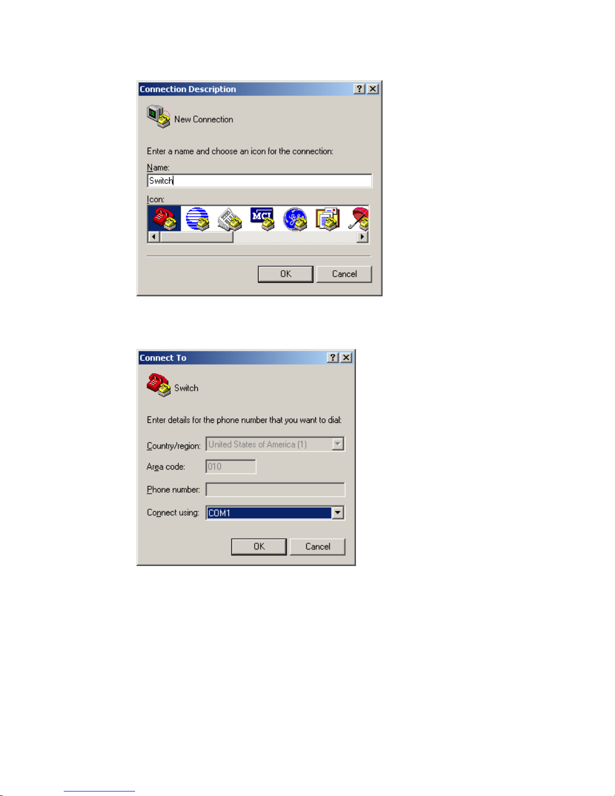
1. Select Start > All Programs > Accessories > Communications > HyperTerminal.
The Connection Description dialog box appears.
2. Enter the name of the new connection in the Name field and click OK.
Page 44
38
Figure 31 Connection description
3. Select the serial port to be used from the Connect using list, and click OK.
Figure 32 Setting the serial port used by the HyperTerminal connection
4. Set Bits per second to 9600, Data bits to 8, Parity to None, Stop bits to 1, and Flow control to None,
and click OK.
Page 45

39
Figure 33 Setting the serial port parameters
5. Select File > Properties in the HyperTerminal window.
Figure 34 HyperTerminal window
6. On the Settings tab, set the emulation to VT100 and click OK.
Page 46

40
Figure 35 Setting terminal emulation in Switch Properties dialog box
Powering on the switch
Before powering on the switch, verify the following items:
• You know where the emergency power-off switch for the equipment room is located.
• The switch has been securely mounted.
• All the cards have been correctly installed.
• The unused slots have been installed with blank filler panels.
• All the network cables, fibers, power cords, and grounding cables have been correctly connected.
• The input power voltage meets the requirement of the switch.
• The console cable is correctly connected.
• The terminal or PC used for configuration has started, and its configuration parameters have been
set.
To power on the switch:
Turn on the power source of the switch to power on the switch.
The following is sample output you can see on the terminal:
System is starting...
Booting Normal Extend BootWare.
The Extend BootWare is self-decompressing...................................
.....Done!
Page 47

41
****************************************************************************
* *
* BootWare, Version 1.00 *
* *
****************************************************************************
Compiled Date : Jul 1 2010
CPU Type : XLS408
CPU L1 Cache : 32KB
CPU Clock Speed : 1000MHz
Memory Type : DDR2 SDRAM
Memory Size : 1024MB
Memory Speed : 533MHz
BootWare Size : 508KB
Flash Size : 128MB
BASIC CPLD Version : 0.0
EXTEND CPLD Version : 0.0
PCB Version : Ver.A
BootWare Validating...
Press Ctrl+B to enter extended boot menu...
Starting to get the main application file--flash:/ 10500.bin!................
.........................................................................
The main application file is self-decompressing.............................
............................................................................
..Done!
System application is starting...
Starting to get the main application file--flash:/ 10500.bin!................
..........................................................................
The main application file is self-decompressing.............................
............................................................................
............................................................................
.....Done!
System application is starting...
User interface aux0 is available.
Press ENTER to get started.
Press Enter at the prompt. When the prompt <Sysname> appears, you can configure the switch.
After powering on the switch, verify the following items:
• The cooling system is operating, and you can hear fan rotating noise and feel air being blown out.
• The system status LEDs on the MPUs show that the system is operating correctly. For more
information about LED behaviors, see "Appendix C LEDs."
Configuring the switch
By default, the switch does not authenticate the console login user at an AUX interface. To increase
system security and enable remote management:
Page 48

42
• Configure remote access services, for example, Telnet or SSH.
• Configure authentication on each user interface, including the AUX interfaces.
Configuring authentication on a user interface
You can configure authentication on a user interface to control access to the switch.
Table 9 de
scribes the Telnet login authentication methods available for a VTY user interface.
Table 9 Telnet login authentication methods
Authentication
method
Feature Application scenarios
None
Easy to configure, allows any user to Telnet
to your switch, and lowest in security
Lab environments and extremely secure
network environments
Password
Easy to configure, secure, and flat user
management
Environments that do not need granular
privilege management
Username and
password
Complex to configure, secure, and
hierarchical user management
Environments where multiple operators
cooperate to manage the switch
For more information about login methods, see HP 10500 Switch Series Fundamentals Configuration
Guide.
Configuring the basic access function
The switch without any configuration can perform basic data forwarding immediately after it is plugged
into a network. To implement more forwarding features, configure the basic network settings in Table 10
on the s
witch.
Table 10 Basic network settings
Settin
g
Description
IP address Enables remote switch management, for example, by using Telnet.
Static routes Implement static routing.
VLANs Divide the LAN into multiple VLANs for data security.
MSTP Avoids loops in a dual-homed network.
For more information about these features, see HP 10500 Switch Series Configuration Guides.
Verifying the network configuration
To verify the software version and network configuration, execute display commands in any view.
Task Command
Display the name, model, and system software version of the switch. display version
Display the current configuration of the switch. display current-configuration
Display the interface status and configuration. display interface brief
Page 49

43
Task Command
Display the IP configuration of Layer 3 interfaces. display ip interface brief
Display information about active routes in the routing table. display ip routing-table
Display VLAN settings. display vlan
Display the spanning tree status and statistics. display stp brief
Connecting the switch to the network
Before you connect the switch to the network, verify that all its basic settings are correct.
Connecting your switch to the network through twisted pair
cables
You can connect the 10/100Base-TX ports, 1000Base-T ports, and 10GBASE-T ports on your switch to
the network. These ports use RJ-45 connectors and support MDI/MDI-X auto-sensing. Use category-6A
or category-7 twisted pair cables to connect 10GBASE-T ports and category-5 or above to connect other
ports. For more information about twisted pair cables, see "Appendix D Cables."
To connect a 10/100Base-TX port, a 1000Base-T port, or a 10GBASE-T port to a peer device:
1. Connect one end of a twisted pair cable to the port.
2. Connect the other end of the twisted pair cable to the RJ-45 Ethernet port of the peer device.
3. Verify the port LEDs for incorrect connection.
For more information about the LED status, see "Appendix C LEDs."
Connecting your switch to the network through optical fibers
W
ARNING!
To avoid injury to your eyes, do not stare at the optical fiber interfaces and optical fiber connectors when
connecting optical fibers.
You can install a transceiver module (see "Installing FRUs") in a fiber port and use optical fibers to
connect the port to the network. For more information about optical fibers, see "Appendix D Cables."
To connect a fiber port to a peer device through optical fibers:
1. Install a transceiver module into the port.
2. Remove the dust cover of the optical fiber connector, and clean the end of the optical fiber.
3. Remove the dust plug of the transceiver module, connect one end of the optical fiber to the
transceiver module, and connect the other end to the transceiver module in the peer device.
{ For how to connect an LC connector, see Figure 36.
{ For how to connect an MPO connector, see Figure 37.
4. Examine the port LEDs for incorrect connection.
For more information about the LED status, see "Appendix C LEDs."
Page 50

44
NOTE:
For a QSFP+ module, you do not need to differentiate between the Tx and Rx ports. For other types of
transceiver modules, the Tx port on one end must connect to the RX port on the other end.
Figure 36 Using LC optical fiber connectors to connect transceiver modules
Figure 37 Using an MPO optical fiber connector to connect a QSFP+ module
Testing connectivity
After you connect the switch to the network, use the ping or tracert command to test network connectivity.
For more information about these commands, see HP 10500 Switch Series Command References.
LC plug
SFP module
MPO plug
QSFP+ module
Page 51

45
Troubleshooting
This chapter describes how to troubleshoot your switch.
TIP:
• Clean your switch periodically because the noncompliant operating environments of switches might
cause switch failures.
• Verify the installation environments against the requirements in "Preparing for installation." M
ake sure
the switch operates in a compliant environment.
• Periodically perform the power-on test for the spare switches.
Troubleshooting methods
If your switch fails, you can use the following methods to troubleshoot the switch:
• At the CLI, you can use the related commands to display the hardware information and locate the
hardware failures.
• The MPU provides the LEDs for the fans and cards. You can locate the failures according to the LED
status on the MPU. For more information about the LED status on the MPU, see "Appendix C LEDs."
• The MPU or LPU of the switch provides the port status LEDs, with which you can detect port failures.
For more information about the LED status on the LPU, see "Appendix C LEDs."
I
f you cannot locate failures by following the guidelines in this chapter, contact HP Support. For more
information, see "Support and other resources."
Configuration terminal problems
If the configuration environment setup is correct, the configuration terminal displays boot information
when the switch is powered on. If the setup is incorrect, the configuration terminal displays garbled text
or does not display anything.
No terminal display
If the configuration terminal displays nothing when the switch is powered on, verify the following items:
• The power supply system is operating correctly.
• The MPU is operating correctly.
• The console cable has been connected to the console port of the MPU.
If no problem is found, examine the console cable for the following problems:
• The console cable is connected to an incorrect serial interface (the serial interface in use is not the
one set on the terminal). To solve this problem, select the correct serial interface.
• The console cable is broken. To solve this problem, replace the console cable.
Page 52

46
Garbled terminal display
If terminal display is garbled, verify that the following settings are configured for the terminal, for
example, HyperTerminal:
• Baud rate—9,600.
• Data bits—8.
• Parity—none.
• Stop bits—1.
• Flow control—none.
When you modify the settings for the console port of the switch, configure the same settings for the
console terminal.
Troubleshooting the switch during the operation
Use display commands to examine the configuration for configuration errors or to examine statistics for
exceptions.
If any configuration errors are found, re-configure the switch or restore the factory-default settings.
Power supply system failure
If the switch is operating correctly, the LEDs on the power supply (AC LED and DC LED) are green. For
more information, see "Appendix C LEDs."
After a power supply is powered off, the power LEDs stay ON for several seconds.
If the power LEDs are off or not green, examine the power supply for an exception, as follows:
1. If the DC LED is orange, the power supply has transitioned to the over-temperature protection state.
Examine the cooling system for inadequate ventilation, and make sure every empty slot has been
covered by a blank filler panel.
2. If the DC LED is red, the power supply has transitioned to a self-protection state because of a power
supply problem. Examine the power supply for output short circuit, output over-current, output
over-voltage, input under-voltage, or remote disconnection.
The DC LED also turns red if the input of the power supply is disconnected while any other power
supply is operating correctly. In this case, connect the input or keep the input disconnected as
needed.
3. Examine the power cord connections. If a power cord is loose, re-connect the power cord. If a
power cord is broken, replace it.
4. Examine the power supply installation. If the power supply is not fully seated, re-install the power
supply to make sure it has a close contact with the backplane of the switch.
5. Examine the power supply system. Make sure the power supply system operates correctly and
provides an acceptable voltage.
6. If the switch has empty power supply slots, remove the power supply, install the power supply in
an empty power supply slot after all LEDs on the power supply are off, and verify that the power
supply can operate correctly.
Page 53

47
7. Install a new power supply of the same model in the same slot, and connect it to the same power
input end. If the new power supply can operate correctly, the old power supply has failed. You
must replace the old power supply.
8. If the problem persists, contact HP Support.
Fan failure
Both the MPU and the fan tray provide the fan tray LEDs, including an OK LED and a FAIL LED. When the
fan tray operates correctly, the OK LED is on, and the FAIL LED is off.
If the OK LED is off or the FAIL LED is on, the fan tray has failed. To troubleshoot the fan tray:
1. If both LEDs are off, verify that the power supplies are operating correctly. For more information,
see "Power supply system failure."
2. Verify that the air intakes a
nd exhaust vents of the chassis are not blocked. If they are blocked,
clean them to keep good ventilation.
3. Verify that the fan tray is fully seated. You can remove the fan tray, install it again, and then fasten
the screws.
4. Verify that the empty LPU slots and power supply slots are installed with blank filler panels. If not,
install blank filler panels for them to guarantee good ventilation.
5. If the problem persists, contact HP Support.
MPU failure
The status LEDs on the MPU show the status of a card in the corresponding slot. According to the slot
number of an MPU, you can verify the corresponding LEDs for the MPU.
When the MPU operates correctly, the RUN LED flashes and the ALM LED is off. When the RUN LED is
off, the MPU fails. To troubleshoot the MPU:
1. Verify that the power supply operates correctly. For more information, see "Power supply system
failur
e."
2. Verify that the MPU is fully seated. You can remove the MPU, install it again, and make sure the
MPU is fully seated.
3. Press the RESET button of the MPU to reset the MPU. After the MPU is reset, verify whether the
corresponding RUN LED is on.
4. If the switch has an empty MPU slot, install the MPU in the slot to test the MPU.
5. If the problem persists, contact HP Support.
LPU and switching fabric module failure
Use the card status LEDs on the MPU to identify the failure of the LPU or switching fabric module in a
particular slot.
If a card is operating correctly, the RUN LED flashes and the ALM LED is off. When the RUN LED is off,
the card fails. To troubleshoot the card:
1. Verify that the MPU is operating correctly. For more information, see "MPU failure."
Page 54

48
2. Verify that the software version is compatible with the card. If not, upgrade the software to a
compatible version.
3. Calculate the total power consumption, and make sure your power supplies can provide enough
power. For more information, see "Appendix B FRUs and compatibility matrixes."
4. Verify that the card is fully seated. You can remove the card, install it again, and press the ejector
levers inward until the ejector levers touch the panel tightly.
5. If the switch has empty card slots, install the card in an empty card slot, and verify that the card can
operate correctly.
6. If the problem persists, contact HP Support.
Interface failure
The interfaces provided by MPUs and LPUs all have corresponding LEDs. When an interface connected
to the network operates correctly, the corresponding LED is on.
NOTE:
A
management Ethernet interface or XFP interface each has two LEDs, LINK and ACT. The LED in this
section for such an interface refers to the LINK LED. Each interface of any other type has only one LED.
If the LED of an interface connected to the network is off, the interface or the connecting cable might fail.
To troubleshoot the interface:
1. Make sure the MPU or LPU where the interface resides operates correctly. For more information,
see "MPU failure" or "LPU and switching fabric module failure."
2. Examine the cable connection of the interface. For how to correctly connect the cable to an
Ethernet interface with an RJ-45 connector or an optical interface, see "Connecting your switch to
the network."
3. Verify that the cable is in good condition. Use the cable to connect two interfaces of the same type
that operate correctly. If the LEDs of the two interfaces are on, the cable is normal. Otherwise, the
cable fails. Use a compliant cable to connect the interface. For more information about the
compliant cables, see "Appendix D Cables."
4. If the interface uses a transceiver module, make sure the interface type is compatible with the
transceiver and that the transceiver is compatible with the cable. For more information, see
"Appendix B FRUs and compatibility matrixes."
5. If the interface uses a transceiver module, make sure the current transceiver module operates
correctly by replacing a normal transceiver module.
6. If the interface is a combo interface (which contains a fiber and a copper port), make sure the port
used for connection is activated for the combo interface. Then, use the combo enable { copper |
fiber } command to activate the port, and verify the LED.
Page 55

49
NOTE:
• A combo interface is a logical interface that comprises one fiber port (Gigabit/100-Mbps SFP port) and
one copper port (10/100/1000Base-T GE port). The two ports share one interface view and cannot
operate simultaneously. When you use the combo enable { copper | fiber } command to enable one
port, the other port is disabled automatically.
• If a port is brought down by the shutdown command, use the undo shutdown command to brin
g
up the
interface.
• After an interface fails, if the switch has an idle interface of the same type, you can connect the cable to
the idle interface.
7. Verify that the speed and duplex settings of the interfaces of a link are the same. Make sure two
interfaces can operate together.
8. If the problem persists, contact HP Support.
Page 56

50
Replacement procedures
CAUTION:
W
hen replacing FRUs while the switch is running, be aware of electrical safety hazards.
The switch uses a modular, hot-swappable architecture, and supports FRUs. You can replace any of FRUs
when the switch is running.
Replacing a power supply
W
ARNING!
• Follow the procedures shown in Figure 38 an
d Figure 39 to replace a power supply to avoid device or
bodily injury.
• Power modules on a 10500 switch must be the same model. When the replacement power modules and
the power modules that are operating correctly are not the same model, power off the switch and
remove all power modules before replacement.
• Add a circuit breaker to the power line for each power supply. Before replacin
g
a power supply, turn off
its circuit breaker.
• The power supply might be of high temperature. Remove it with caution.
• To install the removed power supply to the chassis again, install it after the status LED on it is off.
• After removing the power supply, if you do not install a new power supply, install a blank filler panel.
Figure 38 Power supply removal flow
Figure 39 Power supply installation flow
To replace a power supply:
1. Prepare an antistatic mat to place the removed power supply.
2. Wear an ESD wrist strap and make sure it makes good skin contact and is reliably grounded. For
more information, see "Installing FRUs."
3. Switc
h off the circuit breaker on the power supply.
4. Remove the cable ties from the power cord, and remove the power cord from the power supply.
5. Use a Phillips screwdriver to loosen the captive screw on the power supply, and then grasp the
captive screw between your thumb and index finger to carefully pull out the handle on the power
supply, as shown by callout 1 in Figure 40.
6. Holding the p
ower supply handle with one hand and, supporting the bottom of the power supply
with the other, gently pull the power supply out, as shown by callout 2 in Figure 40.
Page 57

51
7. Put the removed power supply on the antistatic mat.
8. Install a new power supply. For the installation procedures, see "Installing FRUs."
Figure 40 Removing the power suppl
y
(1) Loosen the captive screw (2) Pull the power supply out
Replacing a card
The cards can be installed in horizontal or vertical slots, and the replacement procedures are the same.
The following takes a card installed in a horizontal slot as an example.
To replace a card:
1. Prepare an antistatic mat to place the removed card.
2. Wear an ESD wrist strap and make sure it makes good skin contact and is reliably grounded. For
more information, see "Installing FRUs."
3. If the c
ard is an MPU or LPU, remove all its cables.
4. Use a Phillips screwdriver to remove the captive screw on the card, as shown by callout 1 in Figure
41.
1
2
Page 58

52
5. Move the ejector levers outwards to separate the card from the backplane, as shown by callout 2
in Figure 41.
6. Use on
e hand to slowly move the card outwards. Supporting the bottom of the card with the other
hand, pull the card out of the slot along slide rails, as shown by callout 3 in Figure 41.
7. Put the rem
oved card on the antistatic mat.
8. Install a new card. For the installation procedures, see "Installing FRUs."
9. If no new
card is to be installed, install a blank filler panel to ensure adequate ventilation and dust
prevention.
Figure 41 Replacing a card
(1) Loosen the captive screw. (2) Move the ejector levers outwards.
(3) Take out the card.
Replacing a fan tray
CAUTION:
To avoid bodily injury, do not touch the rotating fans when replacing the fan tray.
When the fan tray fails, replace the fan tray to ensure correct operation of the switch.
The fan tray removal and installation procedures for all 10500 switches are the same, even though the
fan tray sl o t is ver tically oriented for the 10504, 10508, and 10512 switches and horizontally oriented for
the 10508-V switch. This section describes removing and installing a vertically oriented fan tray on a
10508 as an example.
Page 59

53
Removing a fan tray
CAUTION:
To ensure good ventilation, install a new fan tray within 2 minutes after removing the old one.
To remove a fan tray:
1. Prepare an antistatic mat to place the fan tray to be removed.
2. Put on an ESD wrist strap and make sure the wrist strap makes good skin contact and is reliably
grounded. For more information, see "Installing FRUs."
3. Loosen the captive screws on the fan tray, as shown by callout 1 in Figure 42.
4. Hold the handle of the fan tray with one hand to gently
pull the fan tray part way out of the chassis.
After the fans stop rotating, support the bottom of the fan tray with the other hand, and take out the
fan tray from the chassis, as shown by callout 2 in Figure 42.
5. Put the rem
oved fan tray on the antistatic mat.
Figure 42 Removing a fan tray
(1) Loosen the captive screws on the fan tray.
(2) Take the fan tray out of the chassis.
Installing a fan tray
1. Wear an ESD wrist strap and make sure the wrist strap makes good skin contact and is reliably
grounded. For more information, see "Installing FRUs."
2. Take out the fan tray from its package.
Page 60

54
3. Holding the handle of the fan tray with one hand and supporting bottom with the other, gently slide
the fan tray along the guide rails into the slot until it is firmly secured in the slot.
4. Fasten the captive screws on the fan tray.
Replacing a transceiver module
W
ARNING!
W
hen you install or remove a transceiver module:
• Do not stare at the fibers to avoid hurting your eyes.
• Do not touch the golden plating on the module.
Make sure the optical transceiver modules at the two ends of an optical fiber are the same model.
Replacing an XFP/SFP+/SFP/QSFP+ module
1. Wear an ESD wrist strap and make sure it makes good skin contact and is reliably grounded. For
more information, see "Installing FRUs."
2. Remov
e the optical fibers on the module.
3. Pivot the clasp down to the horizontal position (not necessary for a QSFP+ module with a plastic
pull latch).
4. Grasp the clasp on the module and carefully pull the module out of the socket.
5. Put the dust plug on the removed module, and put the remove module into its original shipping
materials.
6. Install a new module. For the installation procedures, see "Installing FRUs."
Replacing a CFP module
1. Wear an ESD wrist strap and make sure it makes good skin contact and is reliably grounded.
For more information, see "Installing FRUs."
2. Remove the optical fibers on the module.
3. Loosen the captive screws on the module.
4. Carefully pull the module out of the slot.
5. Put the dust plug on the removed module, and put the removed module into its original shipping
materials.
6. Install a new module.
For the installation procedures, see "Installing FRUs."
Replacing an SFP+/QSFP+/QSFP+ to SFP+ cable
1. Wear an ESD wrist strap and make sure it makes good skin contact and is reliably grounded. For
more information, see "Installing FRUs."
2. Gently press the c
able plug in, and then pull the handle on the cable outward to pull out the cable
connector.
Page 61

55
3. Install a new cable. For the installation procedures, see "Installing FRUs."
The bend radius of the cable must be a minimum of eight times the cable diameter.
If the cable cannot be removed or installed, verify that the removal or installation process was followed
correctly.
Page 62

56
Support and other resources
Contacting HP
For worldwide technical support information, see the HP support website:
http://www.hp.com/support
Before contacting HP, collect the following information:
• Product model names and numbers
• Technical support registration number (if applicable)
• Product serial numbers
• Error messages
• Operating system type and revision level
• Detailed questions
Subscription service
HP recommends that you register your product at the Subscriber's Choice for Business website:
http://www.hp.com/go/wwalerts
After registering, you will receive email notification of product enhancements, new driver versions,
firmware updates, and other product resources.
Related information
Documents
To find related documents, browse to the Manuals page of the HP Business Support Center website:
http://www.hp.com/support/manuals
• For related documentation, navigate to the Networking section, and select a networking category.
• For a complete list of acronyms and their definitions, see HP A-Series Acronyms.
Websites
• HP.com http://www.hp.com
• HP Networking http://www.hp.com/go/networking
• HP manuals http://www.hp.com/support/manuals
• HP download drivers and software http://www.hp.com/support/downloads
• HP software depot http://www.software.hp.com
• HP Education http://www.hp.com/learn
Page 63

57
Conventions
This section describes the conventions used in this documentation set.
Command conventions
Convention Description
Boldface Bold text represents commands and keywords that you enter literally as shown.
Italic Italic text represents arguments that you replace with actual values.
[ ] Square brackets enclose syntax choices (keywords or arguments) that are optional.
{ x | y | ... }
Braces enclose a set of required syntax choices separated by vertical bars, from which
you select one.
[ x | y | ... ]
Square brackets enclose a set of optional syntax choices separated by vertical bars, from
which you select one or none.
{ x | y | ... } *
Asterisk-marked braces enclose a set of required syntax choices separated by vertical
bars, from which you select at least one.
[ x | y | ... ] *
Asterisk-marked square brackets enclose optional syntax choices separated by vertical
bars, from which you select one choice, multiple choices, or none.
&<1-n>
The argument or keyword and argument combination before the ampersand (&) sign can
be entered 1 to n times.
# A line that starts with a pound (#) sign is comments.
GUI conventions
Convention Description
Boldface
Window names, button names, field names, and menu items are in bold text. For
example, the New User window appears; click OK.
> Multi-level menus are separated by angle brackets. For example, File > Create > Folder.
Symbols
Convention Description
WARNING
An alert that calls attention to important information that if not understood or followed can
result in personal injury.
CAUTION
An alert that calls attention to important information that if not understood or followed can
result in data loss, data corruption, or damage to hardware or software.
IMPORTANT
An alert that calls attention to essential information.
NOTE
An alert that contains additional or supplementary information.
TIP
An alert that provides helpful information.
Page 64

58
Network topology icons
Represents a generic network device, such as a router, switch, or firewall.
Represents a routing-capable device, such as a router or Layer 3 switch.
Represents a generic switch, such as a Layer 2 or Layer 3 switch, or a router that supports
Layer 2 forwarding and other Layer 2 features.
Represents an access controller, a unified wired-WLAN module, or the switching engine
on a unified wired-WLAN switch.
Represents an access point.
Represents a mesh access point.
Represents omnidirectional signals.
Represents directional signals.
Represents a security product, such as a firewall, UTM, multiservice security gateway, or
load-balancing device.
Represents a security card, such as a firewall, load-balancing, NetStream, SSL VPN, IPS,
or ACG card.
Port numbering in examples
The port numbers in this document are for illustration only and might be unavailable on your device.
Page 65

59
Appendix A Chassis views and technical
specifications
Chassis views
Every switch chassis has an MPU section, LPU section, switching fabric module section, power supply
module section, and fan tray section. Figure 43 u
ses the 10508 as an example.
Figure 43 Front and rear views of the 10508
Table 11 Chassis structure
Section Descri
p
tion Remarks
(1) LPU slots
Both LPUs and LPU slots are purple
edged for easy identification.
N/A
(2) MPU slots
Both MPUs and MPU slots are pink
edged for easy identification.
You must install a minimum of one MPU.
(3) Power
supply slots
• The 10504 has four power supply
slots.
• The 10 508, 1050 8-V, a nd 10 512
have six power supply slots.
N/A
Page 66

60
Section Description Remarks
(4) Fan tray slot
Location of the fan tray slot:
• 105 04, 10508, and 10512—Left
rear of the chassis
• 105 08-V—Upper rear of the
chassis
Every 10500 switch comes with one or two fan
trays. You do not need to order fan trays.
(5) Switching
fabric module
slots
Both switching fabric modules and
switching fabric module slots have
silver gray edges.
A 10500 switch requires two to four switching
fabric modules, and one of them must be installed
in one of the two lowest numbered switching fabric
module slots.
For more information about available cards, power supplies, and fan trays, see "Appendix B FRUs and
compatibility matrixes."
Weights and dimensions
Table 12 Switch weights and dimensions
Model Wei
g
ht Height
Width
Dep
th
10504 < 85 kg (187.39 lb)
353 mm (13.90 in)
(8 RU)
440 mm (17.32
in)
660 mm (25.98
in)
10508
< 125 kg (275.57
lb)
620 mm (24.41 in)
(14 RU)
440 mm (17.32
in)
660 mm (25.98
in)
10508-V
< 145 kg (319.66
lb)
886 mm (34.88 in)
(20 RU)
440 mm (17.32
in)
660 mm (25.98
in)
10512
< 165 kg (363.76
lb)
797 mm (31.38 in)
440 mm (17.32
in)
660 mm (25.98
in)
NOTE:
Rack height is measured in RUs. One RU is 44.45 mm (1.75 in).
Table 13 Card weights and dimensions
Card model Wei
g
ht Height
Width
Dep
th
LSU1SUPA0 2.83 kg (6.24 lb) 40 mm (1.57 in) 399 mm (15.71 in) 352 mm (13.86 in)
LSU1SUPB0 2.97 kg (6.55 lb) 40 mm (1.57 in) 399 mm (15.71 in) 352 mm (13.86 in)
LSU1TGS16SC0 3.29 kg (7.25 lb) 40 mm (1.57 in) 399 mm (15.71 in) 352 mm (13.86 in)
LSU1TGS8SE0 3.03 kg (6.68 lb) 40 mm (1.57 in) 399 mm (15.71 in) 352 mm (13.86 in)
LSU1GT48SE0 3.31 kg (7.30 lb) 40 mm (1.57 in) 399 mm (15.71 in) 352 mm (13.86 in)
LSU1GP48SE0 3.25 kg (7.16 lb) 40 mm (1.57 in) 399 mm (15.71 in) 352 mm (13.86 in)
LSU1GP24TXSE0 3.08 kg (6.79 lb) 40 mm (1.57 in) 399 mm (15.71 in) 352 mm (13.86 in)
LSU1GP24TSE0 3.01 kg (6.64 lb) 40 mm (1.57 in) 399 mm (15.71 in) 352 mm (13.86 in)
LSU1TGX4SE0 2.93 kg (6.46 lb) 40 mm (1.57 in) 399 mm (15.71 in) 352 mm (13.86 in)
LSU1TGS32SF0 3.45 kg (7.61 lb) 40 mm (1.57 in) 399 mm (15.71 in) 352 mm (13.86 in)
Page 67

61
Card model Weight Height
Width
Dep
th
LSU1TGS48SF0 4.13 kg (9.10 lb) 40 mm (1.57 in) 399 mm (15.71 in) 352 mm (13.86 in)
LSU1QGS4SF0 3.14 kg (6.92 lb) 40 mm (1.57 in) 399 mm (15.71 in) 352 mm (13.86 in)
LSU1QGS8SF0 3.37 kg (7.43 lb) 40 mm (1.57 in) 399 mm (15.71 in) 352 mm (13.86 in)
LSU1QGC4SF0 3.47 kg (7.65 lb) 40 mm (1.57 in) 399 mm (15.71 in) 352 mm (13.86 in)
LSU1CGC2SE0 3.97 kg (8.75 lb) 40 mm (1.57 in) 399 mm (15.71 in) 352 mm (13.86 in)
LSU1TGT24SF0 3.53 kg (7.78 lb) 40 mm (1.57 in) 399 mm (15.71 in) 352 mm (13.86 in)
LSU1TGS8EA0 3.43 kg (7.56 lb) 40 mm (1.57 in) 399 mm (15.71 in) 352 mm (13.86 in)
LSU1GT48EA0 3.31 kg (7.30 lb) 40 mm (1.57 in) 399 mm (15.71 in) 352 mm (13.86 in)
LSU1GP48EA0 3.25 kg (7.16 lb) 40 mm (1.57 in) 399 mm (15.71 in) 352 mm (13.86 in)
LSU1GP24TXEA0 3.08 kg (6.79 lb) 40 mm (1.57 in) 399 mm (15.71 in) 352 mm (13.86 in)
LSU1TGX4EA0 2.93 kg (6.46 lb) 40 mm (1.57 in) 399 mm (15.71 in) 352 mm (13.86 in)
LSU1TGS8EB0 3.44 kg (7.58 lb) 40 mm (1.57 in) 399 mm (15.71 in) 352 mm (13.86 in)
LSU1GP48EB0 3.25 kg (7.16 lb) 40 mm (1.57 in) 399 mm (15.71 in) 352 mm (13.86 in)
LSU1GP24TXEB0 3.08 kg (6.79 lb) 40 mm (1.57 in) 399 mm (15.71 in) 352 mm (13.86 in)
LSU1TGX4EB0 2.93 kg (6.46 lb) 40 mm (1.57 in) 399 mm (15.71 in) 352 mm (13.86 in)
LSU1FAB04A0 1.61 kg (3.55 lb) 40 mm (1.57 in) 256 mm (10.08 in) 298 mm (11.73 in)
LSU1FAB08A0 2.53 kg (5.58 lb) 40 mm (1.57 in) 426 mm (16.77 in) 298 mm (11.73 in)
LSU1FAB04B0 1.71 kg (3.77 lb) 40 mm (1.57 in) 256 mm (10.08 in) 298 mm (11.73 in)
LSU1FAB04D0 1.71 kg (3.77 lb) 40 mm (1.57 in) 256 mm (10.08 in) 298 mm (11.73 in)
LSU1FAB08B0 2.5 kg (5.51 lb) 40 mm (1.57 in) 426 mm (16.77 in) 298 mm (11.73 in)
LSU1FAB08D0 2.77 kg (6.11 lb) 40 mm (1.57 in) 426 mm (16.77 in) 298 mm (11.73 in)
LSU1FAB12B0 3.98 kg (8.77 lb) 40 mm (1.57 in) 602 mm (23.70 in) 298 mm (11.73 in)
LSU1FAB12D0 4.51 kg (9.94 lb) 40 mm (1.57 in) 602 mm (23.70 in) 298 mm (11.73 in)
LSU3WCMD0 3.62 kg (7.98 lb) 40 mm (1.57 in) 399 mm (15.71 in) 352 mm(13.86 in)
LSU1FWCEA0 3.9 kg (8.60 lb) 40 mm (1.57 in) 399 mm (15.71 in) 352 mm (13.86 in)
Table 14 Power supply weights and dimensions
Model Wei
g
ht Height
Width
Dep
th
2500W AC
Power Supply
2.5 kg (5.51 lb)
41 mm (1.61 in) 102 mm (4.02 in) 410 mm (16.14 in)
2400W DC
Power Supply
2.4 kg (5.29 lb)
41 mm (1.61 in) 102 mm (4.02 in) 410 mm (16.14 in)
Table 15 Fan tray weights and dimensions
Fan tra
y
Weight Height
Width
Dep
th
10504 fan tray 4.7 kg (10.36 lb) 106 mm (4.17 in) 255 mm (10.04 in) 643 mm (25.32 in)
10508 fan tray 6.95 kg (15.32 lb) 112 mm (4.41 in) 425 mm (16.73 in) 645 mm (25.39 in)
Page 68

62
Fan tray Weight Height
Width
Dep
th
10508-V fan tray 8.3 kg (18.30 lb) 80 mm (3.15 in) 440 mm (17.32 in) 654 mm (25.75 in)
10512 upper fan
tray
4.49 kg (9.90 lb) 84 mm (3.31 in) 301 mm (11.85 in) 646 mm (25.43 in)
10512 lower fan
tray
3.61 kg (7.96 lb) 84 mm (3.31 in) 301 mm (11.85 in) 646 mm (25.43 in)
Module power consumption and system power
consumption
Card power consumption
The power consumption of the cards depends on the card model and state. Table 16 shows the power
consumption for different card models.
• The static power consumption of a card refers to the power consumed by the card when the card is
running but all ports on the card are down and when no transceiver module is available on the
optical interface of the card.
• The dynamic power consumption of a card refers to the power consumed by the card when all the
ports on the card are link up and send broadcasts.
Table 16 Card power consumption
Model
Minimum static power
consum
p
tion
Maximum dynamic power
consum
p
tion
LSU1SUPA0 38 W 50 W
LSU1SUPB0 45 W 50 W
LSU1TGS16SC0 84 W 115 W
LSU1TGS8SE0 104 W 135 W
LSU1GT48SE0 67 W 95 W
LSU1GP48SE0 44 W 95 W
LSU1GP24TXSE0 54 W 95 W
LSU1GP24TSE0 47 W 75 W
LSU1TGX4SE0 53 W 80 W
LSU1TGS32SF0 126 W 170 W
LSU1TGS48SF0 164 W 255 W
LSU1QGS4SF0 82 W 100 W
LSU1QGS8SF0 100 W 135 W
LSU1QGC4SF0 53 W 85 W
LSU1CGC2SE0 163 W 220 W
LSU1TGT24SF0 103 W 190 W
Page 69

63
Model
Minimum static power
consum
p
tion
Maximum dynamic power
consum
p
tion
LSU1TGS8EA0 111 W 140 W
LSU1GT48EA0 67 W 95 W
LSU1GP48EA0 44 W 95 W
LSU1GP24TXEA0 54 W 95 W
LSU1TGX4EA0 53 W 80 W
LSU1TGS8EB0 117 W 170 W
LSU1GP48EB0 43 W 110 W
LSU1GP24TXEB0 51 W 100 W
LSU1TGX4EB0 53 W 80 W
LSU1FAB04A0 41 W 50 W
LSU1FAB08A0 68 W 85 W
LSU1FAB04B0 48 W 65 W
LSU1FAB04D0 60 W 80 W
LSU1FAB08B0 44 W 60 W
LSU1FAB08D0 101 W 135 W
LSU1FAB12B0 107 W 140 W
LSU1FAB12D0 195 W 255 W
LSU3WCMD0 118 W 150 W
LSU1FWCEA0 109 W 157 W
Fan tray power consumption
The switch uses fans with the automatic speed adjustment function. The fan speed is automatically
adjusted based on the heat dissipation condition of the switch. The power consumed by a fan tray
depends on the fan speed. Table 17 sho
ws the power consumption of different fan trays.
Table 17 Fan tray power consumption
Model
Minimum fan tray power
consum
p
tion
Maximum fan tray power
consum
p
tion
10504 12 W 240 W
10508 11 W 234 W
10508-V 13 W 329 W
10512 (upper fan tray) 9 W 200 W
10512 (lower fan tray) 7 W 124 W
Page 70

64
System power consumption
The system power consumption of the switch depends on the type and number of cards and the fan tray
power consumption.
• The minimum system power consumption is the total static power consumption of all cards plus the
minimum fan tray power consumption. For example, for a 10508 switch that has two LSU1SUPA0
MPUs, two LSU1TGX4EB0 LPUs, two LSU1FAB08A0 switching fabric modules, and one fan tray,
the minimum system power consumption of the switch is 2 × 38 + 2 × 53 + 2 × 68 + 11 = 329 W.
• The maximum system power consumption is the total dynamic power consumption of all cards plus
the maximum fan tray power consumption. For example, for a 10508 switch that has two
LSU1SUPA0 MPUs, two LSU1TGX4EB0 LPUs, two LSU1FAB08A0 switching fabric modules, and
one fan tray, the maximum system power consumption of the switch is 2 × 50 + 2 × 80 + 2 × 85
+234 = 664 W.
Heat dissipation
Heat dissipation is measured in BTU/h, and 1 W equals 3.4121BTU/h.
The heat dissipation of the switch depends on its power consumption. To calculate heat dissipation of the
switch, assume 90% power consumption is converted to heat, and the efficiency of the power supply is
90%. Heat dissipation/hour of the switch is 0.9 × (total power consumption of the cards plus power
consumption of the fan tray)/0.9 × 3.4121.
For the power consumption of cards and fan trays, see "Module power consumption and system power
co
nsumption."
Environmental specifications
Table 18 Environmental specifications
Descri
p
tion Operating Non-operating
Temperature 0°C to 45°C (32°F to 113°F) –40°C to +70°C (–40°F to +158°F)
Relative humidity 10% to 95% (non-condensing) 5% to 95% (non-condensing)
Noise
The switch uses fans with the automatic speed adjustment function, so the sound pressure levels are
different when the fan speeds are different. For more information, see Table 19.
Table 19 Sound pressu
re levels
Model
Sound pressure level under
acce
p
table temperature
Sound pressure level when the
fan tra
y op
erates at full speed
10504 62.3 dBA 75.5 dBA
10508 63 dBA 75.8 dBA
10508-V 61.6 dBA 72.6 dBA
Page 71

65
Model
Sound pressure level under
acce
p
table temperature
Sound pressure level when the
fan tra
y op
erates at full speed
10512 66 dBA 79 dBA
Page 72

66
Appendix B FRUs and compatibility matrixes
This appendix describes the FRUs available for the switch and their compatibility.
All the FRUs listed in this appendix are hot swappable.
MPUs
CAUTION:
Use the Comware V5 software (with the version number R1XXX) for the LSU1SUPA0. Use the Comware
V
7 software (with the version number R2XXX) for the LSU1SUPB0.
MPU is the supervisor engine and core of the control management plane for the switch. The switch
supports the MPUs LSU1SUPA0 and LSU1SUPB0. They are applicable to all 10500 switch models.
MPUs are ordered separately. The switch requires one MPU to operate correctly. You can also install two
MPUs of the same model for redundancy.
Table 20 de
scribes the MPU specifications, and Table 21 shows the MPU product code and model
matrix.
Table 20 MPU specifications
Item Descri
p
tion
Interfaces
• One console port for local or remote dialup configuration management
• One 10/100/1000BASE-T interface for management and upgrade
Interface transmission
rate
• Console port—No greater than 115200 bps and defaults to 9600 bps
• 10/100/1000BASE-T interface—10/100/1000 Mbps
Cables and max
transmission distance
• Console port—15 m (49.21 ft) over common asynchronous serial interface cable
• 10/100/1000BASE-T interface—100 m (328.08 ft) over Category-5 twisted
pairs
Table 21 MPU product code and model matrix
MPU model Product code
HP description
LSU1SUPA0
JC614A
JG375A
HP 10500 Main Processing Unit
HP 10500 TAA-compliant Main Processing Unit
LSU1SUPB0 JG496A
HP 10500 Type A Main Processing Unit with Comware V7 Operating
System
LPUs
The LPUs in Table 22 are compatible with all 10500 switches. Table 23 lists their product codes and
descriptions. For more information about the transceiver modules that each LPU supports, see
"Transceiver modules."
Page 73

67
Table 22 LPU specifications
LPU model Connector
Number of
interfaces
Interface transmission
rate
Available transceiver
modules
LSU1TGS16SC0 LC 16 10 Gbps, 1 Gbps
• 10 - Gig a bi t SF P +
module
• 10 - Gig a bi t SF P + c ab l e
• Gigabit SFP module
LSU1TGS8SE0 LC 8 10 Gbps, 1 Gbps
• 10 - Gig a bi t SF P +
module
• 10 - Gig a bi t SF P + c ab l e
• Gigabit SFP module
LSU1GT48SE0 RJ-45 48 10/100/1000 Mbps N/A
LSU1GP48SE0 LC 48 1000/100 Mbps
• Gigabit SFP module
• 100 -M b ps SF P mo d ul e
LSU1GP24TXSE0
LC 24 1000/100 Mbps
• Gigabit SFP module
• 100 -M b ps SF P mo d ul e
LC 2 10 Gbps 10-Gigabit XFP module
RJ-45 8 10/100/1000 Mbps N/A
LSU1GP24TSE0
LC 24 1000/100 Mbps
• Gigabit SFP module
• 100 -M b ps SF P mo d ul e
RJ-45 8 10/100/1000 Mbps N/A
LSU1TGX4SE0 LC 4 10 Gbps 10-Gigabit XFP module
LSU1TGS32SF0 LC 32 10 Gbps, 1 Gbps
• 10 - Gig a bi t SF P +
module
• 10 - Gig a bi t SF P + c ab l e
• Gigabit SFP module
LSU1TGS48SF0 LC 48 10 Gbps, 1 Gbps
• 10 - Gig a bi t SF P +
module
• 10 - Gig a bi t SF P + c ab l e
• Gigabit SFP module
LSU1QGS4SF0 MPO 4 40 Gbps
• QSFP+ module
• QSFP+ cable
• QSFP+ to SFP+ cable
LSU1QGS8SF0 MPO 8 40 Gbps
• QSFP+ module
• QSFP+ cable
• QSFP+ to SFP+ cable
LSU1QGC4SF0 LC 4 40 Gbps CFP module
LSU1CGC2SE0 LC 2 100 Gbps CFP module
LSU1TGT24SF0 RJ-45 24 10 Gbps, 1 Gbps N/A
LSU1TGS8EA0 LC 8 10 Gbps, 1 Gbps
• 10 - Gig a bi t SF P +
module
• 10 - Gig a bi t SF P + c ab l e
• Gigabit SFP module
Page 74

68
LPU model Connector
Number of
interfaces
Interface transmission
rate
Available transceiver
modules
LSU1GT48EA0 RJ-45 48 10/100/1000 Mbps N/A
LSU1GP48EA0 LC 48 1000/100 Mbps
• Gigabit SFP module
• 100 -M b ps SF P mo d ul e
LSU1GP24TXEA0
LC
24 1000/100 Mbps
• Gigabit SFP module
• 100 -M b ps SF P mo d ul e
2 10 Gbps 10-Gigabit XFP module
RJ-45 8 10/100/1000 Mbps N/A
LSU1TGX4EA0 LC 4 10 Gbps 10-Gigabit XFP module
LSU1TGS8EB0 LC 8 10 Gbps, 1 Gbps
• 10 - Gig a bi t SF P +
module
• 10 - Gig a bi t SF P + c ab l e
• Gigabit SFP module
LSU1GP48EB0 LC 48 1000/100 Mbps
• Gigabit SFP module
• 100 -M b ps SF P mo d ul e
LSU1GP24TXEB0
LC 24 1000/100 Mbps
• Gigabit SFP module
• 100 -M b ps SF P mo d ul e
LC 2 10 Gbps 10-Gigabit XFP module
RJ-45 8 10/100/1000 Mbps N/A
LSU1TGX4EB0 LC 4 10 Gbps 10-Gigabit XFP module
LSU3WCMD0 RJ-45 2
Console port: ≤
115200 bps (default:
9600 bps)
N/A
10/100/1000BASE-T
interface:
10/100/1000 Mbps
LSU1FWCEA0
RJ-45
One console
port
≤ 115200 bps (default:
9600 bps)
N/A
RJ-45+SFP
2 combo
interfaces,
supporting
optical-electri
cal switching
Copper port:
10/100/1000 Mbps
N/A
Fiber port:
1000 Mbps
Gigabit SFP module
Page 75

69
NOTE:
• LSU1CGC2SE0 is only available for the 10500 switches that run the Comware V7 software.
• A combo interface is a logical port that contains an SFP port and an RJ-45 Ethernet port. Only one of
them can be activated at a time.
• The LSU1TGS48SF0 (JC756A) does not support the HP X130 10G SFP+ LC LRM Transceiver (JD093B)
and the HP X240 10G SFP+ SFP+ 7m Direct Attach Copper Cable (JC784C).
• For more information about LSU3WCMD0, see
HP 10500_7500 20G Unified Wired-WLAN Module
Card Manual
.
• For more information about LSU1FWCEA0, see
HP 10500/11900/7500 20Gbps VPN Firewall Card
Manual
.
Table 23 LPU product code and model matrix
LPU model
Product
code
HP description
LSU1TGS16SC0 JC628A HP 10500 16-port 10-GbE SFP+ SC Module
LSU1TGS8SE0
JC631A
JG389A
HP 10500 8-port 10-GbE SFP+ SE Module
HP 10500 8-port 10GbE SFP+ SE TAA-compliant Module
LSU1GT48SE0
JC618A
JG377A
HP 10500 48-port Gig-T SE Module
HP 10500 48-port Gig-T SE TAA-compliant Module
LSU1GP48SE0
JC619A
JG378A
HP 10500 48-port GbE SFP SE Module
HP 10500 48-port GbE SFP SE TAA-compliant Module
LSU1GP24TXSE0
JC617A
JG376A
HP 10500 16-port GbE SFP /8-port GbE Combo / 2-port 10-GbE XFP SE
Module
HP 10500 16-port GbE SFP / 8-port GbE Combo / 2-port 10GbE XFP SE
TAA-compliant Module
LSU1GP24TSE0
JC763A
JG347A
HP 10500 16-port GbE SFP /8-port GbE Combo SE Module
HP 10500 16-port GbE SFP / 8-port GbE Combo SE TAA-compliant
Module
LSU1TGX4SE0
JC620A
JG379A
HP 10500 4-port 10-GbE XFP SE Module
HP 10500 4-port 10GbE XFP SE TAA-compliant Module
LSU1TGS32SF0
JC755A
JG344A
HP 10500 32-port 10GbE SFP+ SF Module
HP 10500 32-port 10GbE SFP+ SF TAA-compliant Module
LSU1TGS48SF0
JC756A
JG345A
HP 10500 48-port 10GbE SFP+ SF Module
HP 10500 48-port 10GbE SFP+ SF TAA-compliant Module
LSU1QGS4SF0
JC757A
JG346A
HP 10500 4-port 40GbE QSFP+ SF Module
HP 10500 4-port 40GbE QSFP+ SF TAA-compliant Module
LSU1QGS8SF0
JG392A
JG393A
HP 10500 8-port 40GbE QSFP+ SF Module
HP 10500 8-port 40GbE QSFP+ SF TAA-compliant Module
LSU1QGC4SF0
JG396A
JG397A
HP 10500 4-port 40GbE CFP SF Module
HP 10500 4-port 40GbE CFP SF TAA-compliant Module
Page 76

70
LPU model
Product
code
HP description
LSU1CGC2SE0
JG916A
JG917A
HP 10500 2-port 100GbE CFP SE Module
HP 10500 2-port 100GbE CFP SE TAA-compliant Module
LSU1TGT24SF0
JG394A HP 10500 24-port 1/10GBASE-T SF Module
JG395A HP 10500 24-port 1/10GBASE-T SF TAA-compliant Module
LSU1TGS8EA0
JC630A
JG388A
HP 10500 8-port 10-GbE SFP+ EA Module
HP 10500 8-port 10GbE SFP+ EA TAA-compliant Module
LSU1GT48EA0
JC623A
JG382A
HP 10500 48-port Gig-T EA Module
HP 10500 48-port Gig-T EA TAA-compliant Module
LSU1GP48EA0
JC622A
JG381A
HP 10500 48-port GbE SFP EA Module
HP 10500 48-port GbE SFP EA TAA-compliant Module
LSU1GP24TXEA0
JC621A
JG380A
HP 10500 16-port GbE SFP /8-port GbE Combo / 2-port 10-GbE XFP EA
Module
HP 10500 16-port GbE SFP / 8-port GbE Combo / 2-port 10GbE XFP EA
TAA-compliant Module
LSU1TGX4EA0
JC624A
JG383A
HP 10500 4-port 10-GbE XFP EA Module
HP 10500 4-port 10GbE XFP EA TAA-compliant Module
LSU1TGS8EB0
JC629A
JG387A
HP 10500 8-port 10-GbE SFP+ EB Module
HP 10500 8-port 10GbE SFP+ EB TAA-compliant Module
LSU1GP48EB0
JC625A
JG384A
HP 10500 48-port GbE SFP EB Module
HP 10500 48-port GbE SFP EB TAA-compliant Module
LSU1GP24TXEB0
JC626A
JG337A
HP 10500 16-port GbE SFP /8-port GbE Combo / 2-port 10-GbE XFP EB
Module
HP 10500 16-port GbE SFP / 8-port GbE Combo / 2-port 10-GbE XFP EB
TAA-compliant Module
LSU1TGX4EB0
JC627A
JG386A
HP 10500 4-port 10-GbE XFP EB Module
HP 10500 4-port 10GbE XFP EB TAA-compliant Module
LSU3WCMD0
JG639A
JG645A
HP 10500/7500 20G Unified Wired-WLAN Module
HP 10500/7500 20G Unified Wired-WLAN TAA-compliant Module
LSU1FWCEA0 JG372A HP 10500/11900/7500 20Gbps VPN Firewall Module
Page 77

71
Switching fabric modules
CAUTION:
• Do not install B-type switchin
g
fabric modules (LSU1FAB04B0, LSU1FAB08B0, and LSU1FAB12B0) and
D-type switching fabric modules (LSU1FAB04D0, LSU1FAB08D0, and LSU1FAB12D0) on the same
switch.
• A-type and B-type switching fabric modules for the 10504 and 10508 switches can be used in the same
chassis, but the performance of B-type modules will be reduced to match the performance of A-type's.
• The switching fabric modules provide a console port for HP Support to maintain the switches. Do not use
the console port if you have not been trained for that.
You can install up to four switching fabric modules in one switch chassis.
Table 24 sho
ws the switching fabric module and chassis compatibility and Table 25 shows the switching
fabric module product code and model matrix.
Table 24 Switching fabric modules and chassis compatibility
Switchin
g
fabric model Compatible chassis
Minimum requirements
LSU1FAB04A0
LSU1FAB04B0
LSU1FAB04D0
10504
A minimum of two switching fabric modules are
required, and either slot 6 or slot 7 must have
one switching fabric module installed.
LSU1FAB08A0
LSU1FAB08B0
LSU1FAB08D0
10508, 10508-V
A minimum of two switching fabric modules are
required, and either slot 10 or slot 11 must have
one switching fabric module installed.
LSU1FAB12B0
LSU1FAB12D0
10512
A minimum of two switching fabric modules are
required, and either slot 14 or slot 15 must have
one switching fabric module installed.
Table 25 Switching fabric product code and model matrix
Switching fabric
model
Product
code
HP description
LSU1FAB04A0 JC615A HP 10504 400Gbps Type A Fabric Module
LSU1FAB04B0
JC751A
JG340A
HP 10504 880Gbps Type B Fabric Module
HP 10504 880Gbps Type B Fabric TAA-compliant Module
LSU1FAB04D0
JC752A
JG341A
HP 10504 1.2Tbps Type D Fabric Module
HP 10504 1.2Tbps Type D Fabric TAA-compliant Module
LSU1FAB08A0 JC616A HP 10508/10508-V 720Gbps Type A Fabric Module
LSU1FAB08B0
JC753A
JG342A
HP 10508/10508-V 1.04Tbps Type B Fabric Module
HP 10508/10508-V 1.04Tbps Type B Fabric TAA-compliant Module
LSU1FAB08D0
JC754A
JG343A
HP 10508/10508-V 2.32Tbps Type D Fabric Module
HP 10508/10508-V 2.32Tbps Type D Fabric TAA-compliant Module
LSU1FAB12B0
JC749A
JG338A
HP 10512 1.52Tbps Type B Fabric Module
HP 10512 1.52Tbps Type B Fabric TAA-compliant Module
Page 78

72
Switching fabric
model
Product
code
HP description
LSU1FAB12D0
JC750A
JG339A
HP 10512 3.44Tbps Type D Fabric Module
HP 10512 3.44Tbps Type D Fabric TAA-compliant Module
Power supplies
The switch supports the HP 10500 2500W AC Power Supply (JC610A) and HP 10500 2400W DC
Power Supply (JC747A). The HP 10500 2500W AC Power Supply is an AC-input, DC-output power
supply and provides a maximum DC output power of 2500 W. The HP 10500 2400W DC Power Supply
is a DC-input, DC-output power supply that provides a maximum DC output power of 2400 W.
Table 26 Power supply specifications
Item 2500W AC
2400W DC
Rated input voltage range 100 VAC to 240 VAC @ 50/60 Hz –48 VDC to –60 VDC
Rated output voltage 12 VDC 12 VDC
Maximum input current 16 A 60 A
Maximum output current
• 208 A (220 VAC)
• 100 A (110 VAC)
200 A
Maximum output power
• 1200 W (110 VAC)
• 2500 W (220 VAC)
2400 W
Temperature requirements
• Operating temperature: –10°C to +50°C (14°F to 122°F)
• Storage temperature: –40°C to +85°C (–40°F to +185°F)
You can select a certain number of power supplies according to the actual power consumption
requirements of your switch. Make sure the total maximum output power of the ordered power supplies
is greater than the system power consumption. HP recommends that you reserve 20% of the maximum
output power.
IMPORTANT:
• Power supplies of different models cannot be installed on the same switch.
• When the temperature of a power supply exceeds the acceptable operating temperature, the power
supply is automatically powered off. When the temperature recovers to the acceptable temperature, the
power supply is automatically powered on.
Fan trays
Table 27 shows the fan trays that each 10500 switch chassis supports. Every 10500 switch comes with
one fan tray installed.
Page 79

73
Table 27 Fan tray specifications
Product
code
HP
description
Alias
Number
of fans
Fan
diameter
Maximum
rotating
s
p
eed
Maximum
air flow
rate
JC632A
HP 10504
Spare Fan
Assembly
10504 fan tray 8
92 mm
(3.62 in)
6000 RPM 960 CFM
JC633A
HP 10508
Spare Fan
Assembly
10508 fan tray 8
120 mm
(4.72 in)
5200 RPM 1440 CFM
JC634A
HP 10508-V
Spare Fan
Assembly
10508-V fan tray 12
120 mm
(4.72 in)
5200 RPM 1152 CFM
JC758A
HP 10512
Spare Top
Fan Tray
Assembly
10512 upper fan
tray
8
120 mm
(4.72 in)
5200 RPM 1040 CFM
JC773A
HP 10512
Spare
Bottom Fan
Tray
Assembly
10512 lower fan tray
4
120 mm
(4.72 in)
5200 RPM 720 CFM
Mounting accessories
Before installing the switch to the rack, install slide rails to the rack. You can order an HP X421 A-Series
Chassis Universal 4-Post Rack Mounting Kit (JC665A), which is referred to as "the rack mounting kit" in
this document.
An HP X421 A-Series Chassis Universal 4-Post Rack Mounting Kit (JC665A) includes cage nuts, screws,
and a pair of slide rails. The length of the slide rails is in the range of 500 mm (19.69 in) to 800 mm
(31.50 in). A pair of slide rails can bear a maximum weight of 350 kg (771.60 lb). Before you use the
slide rails, make sure the following requirements are satisfied:
• The inside depth of the rack falls into the length range of the slide rail.
• The slide rails can support the total weight of the switch chassis and its accessories.
Transceiver modules
The switch supports transceiver modules. You can order transceiver modules according to the transceiver
modules supported by the LPU interfaces. For more information, see Table 22.
T
he switch supports the following transceiver modules:
• 10-Gigabit XFP modules in Table 28
• 1
0-Gigabit SFP+ modules in Table 29
• 1
0-Gigabit SFP+ cables in Table 30
• Gig
abit SFP modules in Table 31
Page 80

74
• 100 - M bp s S FP mo du le s i n Table 32
• QSFP+ modules listed in Table 33
• QSFP+ ca
bles listed in Table 34
• QSFP+ t
o SFP+ cables listed in Table 35
• CFP module li
sted in Table 36
Table 28 XFP module specifications
Product
code
Description
Central
wavelen
gth
(nm)
Fiber
diameter
(μm)
Multimode fiber
modal
bandwidth
(MHz*km)
Max
transmission
distance
JD117B
HP X130 10G XFP LC SR
Transceiver
850
50/125
2000
300 m (984.25
ft)
500 82 m (269.03 ft)
400 66 m(216.54 ft)
62.5/125
220 33 m (108.27 ft)
160 26 m (85.30 ft)
JD108B
HP X130 10G XFP LC LR
Transceiver
1310 9/125
N/A
10 km (6.21
miles)
JD121A
HP X135 10G XFP LC ER
Transceiver
1550 9/125
N/A
40 km (24.86
miles)
JD107A
HP X130 10G XFP LC ZR
Transceiver
1550 9/125
N/A
80 km (49.71
miles)
JG226A
HP X180 10G XFP LC LH
80km 1538.98nm
DWDM Transceiver
1538.98 9/125 N/A
80 km (49.71
miles)
JG227A
HP X180 10G XFP LC LH
80km 1539.77nm
DWDM Transceiver
1539.77 9/125 N/A
80 km (49.71
miles)
JG228A
HP X180 10G XFP LC LH
80km 1540.56nm
DWDM Transceiver
1540.56 9/125 N/A
80 km (49.71
miles)
JG229A
HP X180 10G XFP LC LH
80km 1542.14nm
DWDM Transceiver
1542.14 9/125 N/A
80 km (49.71
miles)
JG230A
HP X180 10G XFP LC LH
80km 1542.94nm
DWDM Transceiver
1542.94 9/125 N/A
80 km (49.71
miles)
JG231A
HP X180 10G XFP LC LH
80km 1558.98nm
DWDM Transceiver
1558.98 9/125 N/A
80 km (49.71
miles)
JG232A
HP X180 10G XFP LC LH
80km 1559.79nm
DWDM Transceiver
1559.79 9/125 N/A
80 km (49.71
miles)
Page 81

75
Product
code
Description
Central
wavelength
(nm)
Fiber
diameter
(μm)
Multimode fiber
modal
bandwidth
(MHz*km)
Max
transmission
distance
JG233A
HP X180 10G XFP LC LH
80km 1560.61nm
DWDM Transceiver
1560.61 9/125 N/A
80 km (49.71
miles)
NOTE:
The 9/125μm single-mode fibers used by modules JG226A through JG233A must conform to ITU-T
G.655, and those used by other modules must conform to ITU-T G.652.
Table 29 SFP+ module specifications
Product
code
Description
Central
wavelength
(nm)
Fiber
diameter (μm)
Multimode fiber
modal bandwidth
(MHz*km)
Maximum
transmission
distance
JD092B
HP X130 10G
SFP+ LC SR
Transceiver
850
50/125
2000 300 m (984.25 ft)
500 82 m (269.03 ft)
400 66 m (216.54 ft)
62.5/125
200 33 m (108.27 ft)
160 26 m (85.30 ft)
JD093B
HP X130 10G
SFP+ LC LRM
Transceiver
1310
50/125
1500, 500 220 m (721.78 ft)
400 100 m (328.08 ft)
62.5/125 200, 160 220 m (721.78 ft)
JD094B
HP X130 10G
SFP+ LC LR
Transceiver
1310 9/125 N/A 10 km (6.21 miles)
JG234A
HP X130 10G
SFP+ LC ER
40km
Transceiver
1550 9/125 N/A 40 km (24.86 miles)
Table 30 SFP+ cable specifications
Product code Descri
p
tion Cable length
JD096C
HP X240 10G SFP+ SFP+ 1.2m Direct Attach
Copper Cable
1.2 m (3.94 ft)
JD097C
HP X240 10G SFP+ SFP+ 3m Direct Attach Copper
Cable
3 m (9.84 ft)
JG081C
HP X240 10G SFP+ SFP+ 5m Direct Attach Copper
Cable
5 m (16.40 ft)
JC784C
HP X240 10G SFP+ SFP+ 7m Direct Attach Copper
Cable
7m (22.97 ft)
Page 82

76
Table 31 Gigabit SFP module specifications
Product
Code
Description
Central
wavelength
(nm)
Fiber
diameter
(μm)
Multimode
fiber modal
bandwidth
(MHz*km)
Maximum
transmission
distance
JD089B
HP X120 1G SFP
RJ45 T Transceiver
N/A
Category-5
twisted pair
N/A 100 m (328.08 ft)
JD118B
HP X120 1G SFP LC
SX Transceiver
850
50/125
500 550 m (1804.46 ft)
400 500 m (1640.42 ft)
62.5/125
200 275 m (902.23 ft)
160 220 m (721.78 ft)
JD119B
HP X120 1G SFP LC
LX Transceiver
1310
9/125 N/A 10 km (6.21 miles)
50/125
500
550 m (1804.46 ft)
400
62.5/125 500 550 m (1804.46 ft)
JD061A
HP X125 1G SFP LC
LH40 1310nm
Transceiver
1310 9/125 N/A 40 km (24.86 miles)
JD062A
HP X120 1G SFP LC
LH40 1550nm
Transceiver
1550 9/125 N/A 40 km (24.86 miles)
JD063B
HP X125 1G SFP LC
LH70 Transceiver
1550 9/125 N/A 70 km (43.50 miles)
JD103A
HP X120 1G SFP LC
LH100 Transceiver
1550 9/125 N/A
100 km (62.14
miles)
JD098B
HP X120 1G SFP LC
BX 10-U Transceiver
TX: 1310
RX: 1490
9/125 N/A 10 km (6.21 miles)
JD099B
HP X120 1G SFP LC
BX 10-D Transceiver
TX: 1490
RX: 1310
9/125 N/A 10 km (6.21 miles)
JD113A
HP X170 1G SFP LC
LH70 1470
Transceiver
1470 9/125 N/A 70 km (43.50 miles)
JD114A
HP X170 1G SFP LC
LH70 1490
Transceiver
1490 9/125 N/A 70 km (43.50 miles)
JD115A
HP X170 1G SFP LC
LH70 1510
Transceiver
1510 9/125 N/A 70 km (43.50 miles)
JD116A
HP X170 1G SFP LC
LH70 1530
Transceiver
1530 9/125 N/A 70 km (43.50 miles)
Page 83

77
Product
Code
Description
Central
wavelength
(nm)
Fiber
diameter
(μm)
Multimode
fiber modal
bandwidth
(MHz*km)
Maximum
transmission
distance
JD109A
HP X170 1G SFP LC
LH70 1550
Transceiver
1550 9/125 N/A 70 km (43.50 miles)
JD110A
HP X170 1G SFP LC
LH70 1570
Transceiver
1570 9/125 N/A 70 km (43.50 miles)
JD111A
HP X170 1G SFP LC
LH70 1590
Transceiver
1590 9/125 N/A 70 km (43.50 miles)
JD112A
HP X170 1G SFP LC
LH70 1610
Transceiver
1610 9/125 N/A 70 km (43.50 miles)
IMPORTANT:
• You must use the HP X120 1G SFP LC BX 10-U Transceiver (JD098B) and the HP X120 1G SFP LC BX
10-D Transceiver (JD099B) in pairs.
• The 100/1000-Mbps SFP port of a combo interface does not support transceiver module JD089B.
Table 32 100-Mbps SFP module specifications
Product
code
Description
Central wavelength
(nm)
Fiber
diameter (μm)
Maximum
transmission
distance
JD102B
HP X115 100M SFP LC FX
Transceiver
1310
50/125
2 km (1.24
miles)
62.5/125
JD120B
HP X110 100M SFP LC LX
Transceiver
1310 9/125
15 km (9.32
miles)
JD090A
HP X110 100M SFP LC LH40
Transceiver
1310 9/125
40 km (24.86
miles)
JD091A
HP X110 100M SFP LC LH80
Transceiver
1550 9/125
80 km (49.71
miles)
JD100A
HP X110 100M SFP LC BX 10-U
Transceiver
TX: 1310
RX: 1550
9/125
15 km (9.32
miles)
JD101A
HP X110 100M SFP LC BX 10-D
Transceiver
TX: 1550
RX: 1310
9/125
15 km (9.32
miles)
IMPORTANT:
You must use the HP X115 100M SFP LC BX 10-U Transceiver (JD100A) and the HP X115 100M SFP LC
BX 10-D Transceiver (JD101A) in pairs.
Page 84

78
Table 33 QSFP+ module specifications
Product
code
Description Connector
Fiber
specifications
Multimode
fiber modal
bandwidth
(MHz*km)
Maximum
transmission
distance
JG325A
HP X140 40G QSFP+
MPO SR4 Transceiver
MPO
MULTIMODE
50/125μm
OM3
2000
100 m (328.08
ft)
JG661A
HP X140 40G QSFP+
LC LR4 SM 10km
1310nm Transceiver
LC 9/125 μm SMF N/A
10 km (6.21
miles)
IMPORTANT:
A
ll Comware V7 software versions (with the version number R2XXX) support the HP X140 40G QSFP+ LC
LR4 SM 10km 1310nm Transceiver (JG661A). For the Comware V5 software versions (with the version
number R1XXX), only Release 1208P03 and later versions support this type of transceiver module.
Table 34 QSFP+ cable specifications
Product code Descri
p
tion Cable length
Remarks
JG326A
HP X240 40G QSFP+ QSFP+ 1m
Direct Attach Copper Cable
1 m (3.28 ft)
Used for connecting 40 Gbps
QSFP+ ports.
JG327A
HP X240 40G QSFP+ QSFP+ 3m
Direct Attach Copper Cable
3 m (9.84 ft)
JG328A
HP X240 40G QSFP+ QSFP+ 5m
Direct Attach Copper Cable
5 m (16.40 ft)
Table 35 QSFP+ to SFP+ cable specifications
Product code Descri
p
tion Cable length
Remarks
JG329A
HP X240 40G QSFP+ to 4x10G
SFP+ 1m Direct Attach Copper
Splitter Cable
1 m (3.28 ft)
Used for connecting a 40
Gbps QSFP+ port to four 10
Gbps SFP+ ports.
JG330A
HP X240 40G QSFP+ to 4x10G
SFP+ 3m Direct Attach Copper
Splitter Cable
3 m (9.84 ft)
JG331A
HP X240 40G QSFP+ to 4x10G
SFP+ 5m Direct Attach Copper
Splitter Cable
5 m (16.40 ft)
Page 85

79
Table 36 CFP module specifications
Product code Description
Central
wavelength(nm)
Fiber
diameter (μm)
Maximum
transmission
distance
JC857A
HP X140 40G CFP LC LR4
10km SM Transceiver
1310 9/125
10 km (6.21
miles)
JG829A
HP X150 100G CFP LC LR4
10km SM Transceiver
1295.56
1300.05
1304.58
1309.14
9/125
10 km (6.21
miles)
DC power cord
DC power cords are used for connecting the HP 10500 2400W DC power supply to the external DC
power supply system.
Table 37 DC power cord specifications
DC
p
ower cord Description Cable length
JG390A HP 10500 -48V 3m DC Power Supply Cable 3 m (9.84 ft)
JG391A HP 10500 -48V 15m DC Power Supply Cable 15 m (49.21 ft)
Page 86

80
Appendix C LEDs
Table 38 lists the LEDs available for you to monitor module status.
Table 38 LEDs at a glance
LEDs
MPU LEDs:
• Management Ethernet port LEDs
• Fan LEDs
• Card LEDs
• MPU active/standby status LED
LPU LEDs:
• RJ-45 Ethernet port LED
• SFP port LED
• SFP+ port LED
• XFP port LEDs
• QSFP+ port LEDs
• CFP port LEDs
Switching fabric module LEDs
Fan tray status LEDs
Power supply LEDs
MPU LEDs
The LEDs for the two types of MPU for the 10500 switches are the same. Figure 44 shows the LEDs
available on the LSU1SUPA0 MPU.
Figure 44 MPU LEDs
(1) Management Ethernet port LEDs (2) Fan LEDs
(3) Card status LEDs (4) MPU active/standby status LED
Management Ethernet port LEDs
Each MPU has one LINK LED and one ACT LED to indicate the link status and data forwarding status of
the management Ethernet port.
Page 87

81
Table 39 Management Ethernet port LED description
LIN
K
ACT Description
On Flashing
A link is present, and the management Ethernet port is receiving or
sending data.
On Off A link is present.
Off Off No link is present.
Fan LEDs
Each MPU provides two sets of LEDs (OK and FAIL) to indicate the status of two fan trays (FAN0 and
FAN1).
The 10504, 10508, and 10508-V switches have only one fan tray. The LED for the fan tray is the FAN0
LED on the MPU.
The 10512 switch has two fan trays. The LEDs for the fan trays are the FAN0 and FAN1 LEDs on the MPU.
Table 40 Fan LED description
O
K
FAIL Description
On Off The fan tray is operating correctly.
Off On A fan problem is present or the fan tray is not in position.
Off Off The switch is not powered on.
Card LEDs
Each MPU has the LEDs numbered the same as card slots to indicate the status of the active MPU, standby
MPU, LPUs, and switching fabric modules in the slots. Table 41 sh
ows the LED description.
NOTE:
Slot numbers are marked on top of the slots on the 10508-V switch and on the ri
g
ht of the slots on other
10500 switches.
Table 41 Card LED description
RUN ALM Descri
p
tion
Flashes once per
second
Off The card is operating correctly.
Flashes once per
second
Flashes once per
4 seconds
The card temperature exceeds the upper warning threshold or falls
below the lower warning threshold.
On On The card is booting or faulty.
On Off The MPU is starting up.
Off Off The card is not in position.
Page 88

82
NOTE:
• When the RUN LED flashes four times per second, the card is loadin
g
software. If the indicator flashes
in this state continuously, the card is not compatible with the switch software.
• The ALM LED for an LPU lights for a period of time at the initial phase of the system startup.
MPU active/standby status LED
Each MPU has one ACTIVE LED to indicate the active or standby status of the MPU.
Table 42 MPU ACTIVE LED description
LED status Descri
p
tion
On The MPU is active.
Off
• The MPU is in standby status.
• The MPU is faulty. Examine the card LED for an MPU problem.
LPU LEDs
RJ-45 Ethernet port LED
Each RJ-45 Ethernet port has one LED to show link status and activities.
Table 43 RJ-45 Ethernet port LED description
LED status Descri
p
tion
Flashing yellow The Ethernet port is receiving or sending data at 100/1000 Mbps.
Flashing green The Ethernet port is receiving or sending data at 10 Gbps.
Steady yellow A 100/1000 Mbps link is present.
Steady green A 10 Gbps link is present.
Off No link is present.
SFP port LED
Each SFP port has one LED to show link status and activities.
Table 44 SFP port LED description
LED status Descri
p
tion
Flashing The SFP port is receiving or sending data.
On A link is present.
Off No link is present.
SFP+ port LED
Each SFP+ port has one LED to show link status and activities.
Page 89

83
Table 45 SFP+ port LED description
LED status Descri
p
tion
Flashing yellow The SFP+ port is receiving or sending data at 100/1000 Mbps.
Flashing green The SFP+ port is receiving or sending data at 10 Gbps.
Steady yellow A 100/1000 Mbps link is present.
Steady green A 10 Gbps link is present.
Off No link is present.
XFP port LEDs
Each XFP port has two LEDs (LINK and ACT) to show link status and activities.
Table 46 XFP port LED description
LIN
K
ACT Description
On Flashing A link is present, and the XFP port is receiving or sending data.
On Off A link is present, but no data is being received or sent.
Off Off No link is present.
QSFP+ port LEDs
Each QSFP+ port has one LED to show link status and activities.
Table 47 QSFP+ port LED description
LED status Descri
p
tion
Flashing The QSFP+ port is receiving or sending data.
On A link is present, but no data is being received or sent.
Off No link is present.
CFP port LEDs
The LPUs provide a LED for each CFP port to indicate the link status and data receiving/forwarding status
of the CFP ports.
Table 48 CFP port LED description
LED status Descri
p
tion
Flashing The CFP port is receiving or sending data.
On A link is present, but no data is being received or sent.
Off No link is present.
Switching fabric module LEDs
The switching fabric module has one RUN LED and one ALM LED to indicate its operating status.
Page 90

84
Table 49 Switching fabric module LED description
RUN LED ALM LED Descri
p
tion
Flashing (0.5 Hz) Off The switching fabric module is operating correctly.
Off On The switching fabric module is faulty.
Flashing (0.5 Hz) On
The temperature of the switching fabric module has exceeded the
upper or lower limit.
Off Off The switching fabric module has not started.
On Off The switching fabric module is up.
Fan tray status LEDs
Each fan tray has one OK LED and one FAIL LED to indicate its operating status.
Table 50 Fan tray LED description
O
K
FAIL Description
On Off The fan tray is operating correctly.
Off On The fan tray is faulty.
Off Off The fan tray is not powered on.
Power supply LEDs
The HP 10500 2500W AC Power Supply has one AC LED and one DC LED to indicate its operating
status.
The HP 10500 2400W DC Power Supply has one INP OK LED and one DC/FLT LED to indicate its
operating status.
Table 51 2500W AC power supply LED description
LED Color
Description
AC
Off
• The power supply has no power input.
• The input voltage is too low, and the power supply is in self protection state.
Green The power input is correct.
DC
Green The power supply is outputting power correctly.
Red
The power supply is experiencing an output problem, including output
short-circuit, output overcurrent, output overvoltage, input under-voltage, or
remote power off, and has entered the self protection state.
Orange
The power supply is in an over-temperature condition and has entered the self
protection state.
Page 91

85
Table 52 2400W DC power supply LED description
LED Color
Description
INP OK
Off
• The power supply has no power input.
• The input voltage is too low, and the power supply is in self protection state.
Green The power input is correct.
DC/FLT
Green The power supply is outputting power correctly.
Red
The power supply is experiencing an output problem, including output
short-circuit, output overcurrent, output overvoltage, input under-voltage, or
remote power off, and has entered the self protection state.
Orange
The power supply is in an over-temperature condition and has entered the self
protection state.
Page 92

86
Appendix D Cables
This chapter describes cables used for connecting network ports.
Table 53 Cable description
Cable Port t
yp
e
App
lication
Console cable
RJ-45 Ethernet port at one
end and DB-9 port at the
other end
Connects the console port of the switch to the
console terminal
Ethernet twisted pair cable RJ-45 Ethernet ports Connects RJ-45 Ethernet ports to transmit data.
Optical fiber
XFP/SFP+/SFP/CFP/QSFP+
ports
Connects the fiber ports to transmit data.
SFP+ cable SFP+ ports Connects SFP+ ports to transmit data.
QSFP+ cable QSFP+ ports Connects QSFP+ ports to transmit data.
QSFP+ to SFP+ cable
QSFP+ port at one end and
SFP+ port at the other end
Connects the QSFP+ port at one end and the
SFP+ port at the other end.
Console cable
A console cable is an 8-core shielded cable, with a crimped RJ-45 connector at one end for connecting
to the console port of the switch, and a DB-9 female connector at the other end for connecting to the
serial port on the console terminal.
Figure 45 Console cable
Ethernet twisted pair cable
An Ethernet twisted pair cable consists of four pairs of insulated wires twisted together. It mainly transmits
analog signals and is advantageous in transmitting data over shorter distances. The maximum
transmission distance is 100 m (328.08 ft).
Page 93

87
RJ-45 connector
An Ethernet twisted pair cable connects network devices through the RJ-45 connectors at the two
ends. Figure 46 sh
ows the pinouts of an RJ-45 connector.
Figure 46 RJ-45 connector pinout diagram
Cable pinouts
EIA/TIA cabling specifications define two standards: 568A and 568B for cable pinouts.
• Standard 568A—Pin 1: white/green stripe, pin 2: green solid, pin 3: white/orange stripe, pin 4:
blue solid, pin 5: white/blue stripe, pin 6: orange solid, pin 7: white/brown stripe, pin 8: brown
solid.
• Standard 568B—Pin 1: white/orange stripe, pin 2: orange solid, pin 3: white/green stripe, pin 4:
blue solid, pin 5: white/blue stripe, pin 6: green solid, pin 7: white/brown stripe, pin 8: brown
solid.
Cable type
Based on performance
Ethernet cables can be classified into category 3, category 4, category 5, category 5e, category 6,
category 6A, and category 7 cables based on performance.
Table 54 Ethernet cable description
T
yp
e Description
Category 5 Transmits data at a maximum speed of 100 Mbps, with a bandwidth of 100 MHz.
Category 5e Transmits data at a maximum speed of 1000 Mbps, with a bandwidth of 100 MHz.
Category 6 Transmits data at a speed higher than 1 Gbps, with a bandwidth of 250 MHz.
Category 6A Transmits data at a speed higher than 10 Gbps, with a bandwidth of 500 MHz.
Category 7 Transmits data at a speed higher than 10 Gbps, with a bandwidth of 600 MHz.
NOTE:
The 10 Gbps RJ-45 Ethernet ports use category 6A or category 7 Ethernet twisted pair cables for
connection. Other RJ-45 Ethernet ports use category 5 or higher Ethernet twisted pair cables for
connection.
PIN #8
PIN #1
Page 94

88
Based on pinouts
Ethernet twisted pair cables can be classified into straight through and crossover cables based on their
pinouts.
• Straight-through—The pinouts at both ends comply with standard 568B, as shown in Figure 47.
• C
rossover—The pinouts at one end comply with standard 568B, and those at the other end comply
with standard 568A, as shown in Figure 48.
Figure 47 Straight-throu
gh cable
Figure 48 Crossover cable
Page 95

89
Pin assignments
Select an Ethernet twisted pair cable according to the RJ-45 Ethernet interface type on your device. An
RJ- 45 Ethernet interface can be MDI (for routers and PCs) or MDIX (for switches) . For the pinouts of RJ-45
Ethernet interfaces, see Table 55 and Table 56.
Table 55 RJ-45
MDI interface pinouts
Pin
10Base-T/100Base-TX
1000Base-T
Sig
nal Function
Sig
nal
Function
1 Tx+ Send data BIDA+ Bi-directional data cable A+
2 Tx- Send data BIDA- Bi-directional data cable A-
3 Rx+ Receive data BIDB+ Bi-directional data cable B+
4 Reserved N/A BIDC+ Bi-directional data cable C+
5 Reserved N/A BIDC- Bi-directional data cable C-
6 Rx- Receive data BIDB- Bi-directional data cable B-
7 Reserved N/A BIDD+ Bi-directional data cable D+
8 Reserved N/A BIDD- Bi-directional data cable D-
Table 56 RJ-45 MDI-X interface pinouts
Pin
10Base-T/100Base-TX
1000Base-T
Sig
nal Function
Sig
nal
Function
1 Rx+ Receive data BIDB+ Bi-directional data cable B+
2 Rx- Receive data BIDB- Bi-directional data cable B-
3 Tx+ Send data BIDA+ Bi-directional data cable A+
4 Reserved N/A BIDD+ Bi-directional data cable D+
5 Reserved N/A BIDD- Bi-directional data cable D-
6 Tx- Send data BIDA- Bi-directional data cable A-
7 Reserved N/A BIDC+ Bi-directional data cable C+
8 Reserved N/A BIDC- Bi-directional data cable C-
To ensure correct commun ic ation, t he pins for sendi ng data on one p o rt should correspon d to the pins for
receiving data on the peer port. When both of the ports on the two devices are MDI or MDIX, a crossover
Ethernet cable is needed. A cross-over cable connects devices of the same type. When one port is MDI
and the other is MDIX, a straight-through Ethernet cable is needed. A straight-through cable connects
devices of different types.
If an RJ-45 Ethernet interface with MDI/MDIX autosensing enabled can automatically negotiate pin roles.
The 10500 RJ-45 Ethernet interfaces support MDI/MDIX. By default, MDI/MDIX autosensing is enabled
on a port.
Page 96

90
Making an Ethernet twisted pair cable
1. Cut the cable to a required length with the crimping pliers.
2. Strip off an appropriate length of the cable sheath. The length is typically that of the RJ-45
connector.
3. Untwist the pairs so that they can lay flat, and arrange the colored wires based on the wiring
specifications.
4. Cut the top of the wires even with one another. Insert the wires into the RJ-45 end and make sure
the wires extend to the front of the RJ-45 end and make good contact with the metal contacts in the
RJ-45 end and in the correct order.
5. Crimp the RJ-45 connector with the crimping pliers until you hear a click.
6. Repeat the above steps with the other end of the cable.
7. Use a cable tester to verify the correct connectivity of the cable.
Optical fiber
CAUTION:
Use the same types of transceiver modules, pigtail cords, patch cords, and fiber cables. If you use
single-mode optical fibers, the transceiver modules, pi
g
tail cords, patch cords, and fiber cables must be
single-mode.
Optical fibers are widely used in fiber-optic communications, which are advantageous for long-distance
communications.
Optical fibers can be classified into the following types:
• Single-mode fiber—It has a core size of 10 μm or smaller, and has a lower modal dispersion. It
carries only a single ray of light. It is mostly used for communication over longer distances.
• Multi-mode fiber—It has a core size of 50 μm or 62.5 μm or higher, and has a higher modal
dispersion than single-mode optical fiber. It is mostly used for communication over shorter
distances.
Table 57 Allowed maximum tensile force and crush load
Period of force Tensile load (N)
Crush load (N/mm)
Short period 150 500
Long term 80 100
Optical fiber cable
An optical fiber cable is a cable containing one or more optical fibers. The optical fiber elements are
typically individually coated with plastic layers and contained in a protective tube. Optical fiber cables
fall into single-mode and multi-mode.
Patch cord
A fiber that has connectors at both ends is called a patch cord. A patch cord connects one optical device
to another for signal routing. Patch cords fall into single-mode and multi-mode patch cords.
• Single-mode patch cord—The jacket is yellow. It permits transmission over longer distances.
Page 97

91
• Multi-mode patch cord—The jacket is orange. It permits transmission over shorter distances.
Patch cords are classified into SC, LC, FC, and so on based on interface type. The length of a patch cord
can be 0.5 m (1.64 ft), 1 m (3.28 ft), 2 m (6.56 ft), 3 m (9.84 ft), 5 m (16.40 ft), 10 m (32.81 ft), and so
on.
Pigtail cord
A pigtail cord is an optical fiber that has an optical connector on one end and a length of exposed fiber
on the other. The end of the pigtail is fusion spliced to a fiber, connecting the fiber cable and transceiver.
Pigtail cords fall into single-mode (yellow) and multi-mode (orange), and can also be classified into SC,
LC, FC, and so on based on interface type.
Fiber connector
Fiber connectors are indispensable passive components in an optical fiber communication system. They
allow the removable connection between optical channels, which makes the optical system debugging
and maintenance more convenient and the transit dispatching of the system more flexible.
Figure 49 SC connector
Figure 50 LC connector
Precautions
• Make sure the fiber connector and fiber type match the transceiver module type.
• The optical interfaces on some cards have shielded covers. Remove the shielded covers before
using the optical interfaces. Optical interfaces must be installed with shielded covers when they are
not in use. Keep them safely.
• Fiber connectors must be protected under safe and reliable outer packing, and be fitted with dust
caps. Fiber connectors must be installed with dust caps when they are not in use. Take care not to
scratch their end face. Replace the dust cap if it is loose or polluted.
• Before connecting a fiber, use dust free paper and absolute alcohol to clean the end face of the
fiber connector. You can brush the end face only in one direction. You also need to brush the end
face of the fiber port.
Page 98

92
• Never bend or curve a fiber when connecting it. After a fiber is installed well, the bend radius must
be not less than 40 mm (the minimum dynamic bend radius is 20 D, and the minimum static bend
radius is 10 D. D indicates the outer diameter of dust caps).
• If the fiber has to pass through a metallic board hole, the hole must have a sleek and fully filleted
surface (the filleting radius must be not less than 2 mm). When passing through a metallic board
hole or bending along the acute side of mechanical parts, the fiber must wear jackets or cushions.
• Insert and remove a plug with care. Never exert a fierce force to the fiber or plug; otherwise the
plug might be damaged or the fiber might be broken. Never pull, press or extrude the fiber fiercely.
For the allowed maximum tensile load and crush load, see Table 57.
SFP+ cable
You can use SFP+ cables to connect SFP+ ports. The SFP+ cables available for the switch are 10 G SFP+
Cu cables, as shown in Figure 51.
Figure 51 SFP+ cable
(1) Connector (2) Pull latch
QSFP+ cable
You can use QSFP+ cables to connect QSFP+ ports.
Figure 52 QSFP+ cable
(1) Connector (2) Pull latch
Page 99
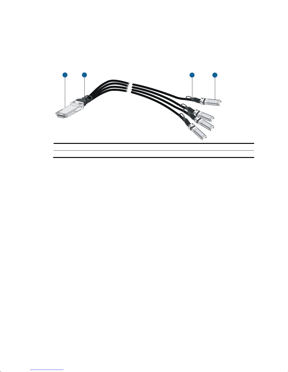
93
QSFP+ to SFP+ cable
A QSFP+ to SFP+ cable is a cable with one QSFP+ module at one end and four SFP+ modules at the
other end.
Figure 53 QSFP+ to SFP+ cable
(1) QSFP+ connector (2) QSFP+ pull latch
(3) SFP+ connector (4) SFP+ pull latch
1
2
34
Page 100

94
Appendix E Cabling recommendations
When the switch is mounted in a 19-inch standard rack, the interface cables are routed through the cable
management brackets, bound at cabling racks on chassis sides, and then routed up or down to pass
through the chassis top or the raised floor, depending on the available equipment room condition. The
power cords run along the two sides of the chassis and out of the chassis either from the chassis top or
the raised floor depending on the equipment room conditions (power distribution cabinet, lightning
protection box, connector strip, and so on) of the exchange office.
General cabling requirements
Minimum curvature radius of cables
• The curvature radius of an attached power cord, communication cable, or ribbon cable should be
a minimum of five times the cable's outer diameter. If the cable is frequently bent, plugged and
unplugged, the curvature radius should be a minimum of seven times the cable's outer diameter.
• The curvature radius of an ordinary attached coaxial cable should be a minimum of seven times of
the cable's outer diameter. If the coaxial cable is frequently bent, plugged and unplugged, the
curvature radius should be a minimum of 10 times the cable's outer diameter.
• The curvature radius of a high-speed cable (for example, SFP+ cable) should be a minimum of five
times of the cable's outer diameter. If the coaxial cable is frequently bent, plugged and unplugged,
the curvature radius should be a minimum of 10 times the cable's outer diameter.
Minimum curvature radius of fibers
• When the fiber is wrapped up around the cabling plate, the diameter of the cabling plate should
be a minimum of 25 times the fiber's diameter.
• When the fiber is being moved, the curvature radius of the fiber should be a minimum of 20 times
the fiber's diameter.
• When the fiber is attached, the curvature radius of the fiber should be a minimum of 10 times the
fiber's diameter.
NOTE:
The fiber's diameter refers to the outer diameter of the fiber jacket. Typically, the diameter of a single-core
fiber is 0.9 mm (0.04 in), 2.0 mm (0.08 in), or 3.0 mm (0.12 in).
Before binding the cables, fill in the labels for them correctly and stick them to the right position on the
cables.
Cable management requirements
When you route and bundle up cables, follow these guidelines:
• Bind and route cables neatly inside the rack, and make sure they are not kinked or bent.
 Loading...