

Page 1
Operating Instructions
COOKER
FRGB
English, 1 Français,
C 31 N1 EX
C 31S N1 EX
SSS
SSS
13
AR
Contents
WARNINGWARNINGWARNING
Installation,
Positioning and levelling
Electrical connection
Gas connection
Adapting to different types of gas
Technical data
Table of burner and nozzle specifications
Description of the appliance,
Overall view
Control panel
Start-up and use,
Using the hob
Using the oven
Practical advice on using the electric hotplates
Practical cooking advice
Oven cooking advice table
Precautions and tips,
General safety
Disposal
Respecting and conserving the environment
,2
3-6
,7
,8-10
,11
GB
Care and maintenance
Switching the appliance off
Cleaning the appliance
Gas tap maintenance
Replacing the oven light bulb
Assistance
,12
Page 2

WARNING
GB
WARNING: The appliance and its
accessible parts become hot
during use.
Care should be taken to avoid
touching heating elements.
Children less than 8 years of age
shall be kept away unless
continuously supervised.
This appliance can be used by
children aged from 8 years and
above and persons with reduced
physical, sensory or mental
capabilities or lack of experience
and knowledge if they have been
given supervision or instruction
concerning use of the appliance in
a safe way and understand the
hazards involved. Children shall not
play with the appliance. Cleaning
and user maintenance shall not be
made by children without
supervision.
The internal surfaces of the
compartment (where present) may
become hot.
Never use steam cleaners or
pressure cleaners on the appliance.
Remove any liquid from the lid
before opening it.
Do not close the glass cover (if
present) when the gas burners or
electric hotplates are still hot.
WARNING: Ensure that the
appliance is switched off before
replacing the lamp to avoid the
possibility of electric shock.
WARNING: Unattended cooking on
a hob with fat or oil can be
dangerous and may result in fire.
NEVER try to extinguish a fire with
water, but switch off the appliance
and then cover flame e.g. with a lid
or a fire blanket.
WARNING: Danger of fire: do not
store items on the cooking
surfaces.
Do not use harsh abrasive cleaners
or sharp metal scrapers to clean
the oven door glass since they can
scratch the surface, which may
result in shattering of the glass.
2
Page 3
Installation
GB
Before operating your new appliance please read
this instruction booklet carefully. It contains
important information concerning the safe installation
and operation of the appliance.
Please keep these operating instructions for future
reference. Make sure that the instructions are kept
with the appliance if it is sold, given away or moved.
The appliance must be installed by a qualified
professional according to the instructions provided.
Any necessary adjustment or maintenance must be
performed after the cooker has been disconnected
from the electricity supply.
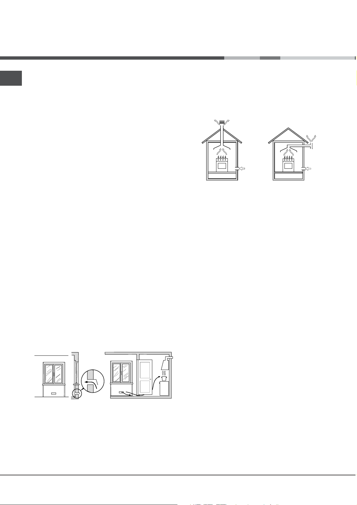
Room ventilation
The appliance may only be installed in permanentlyventilated rooms, according to current national
legislation. The room in which the appliance is
installed must be ventilated adequately so as to
provide as much air as is needed by the normal gas
combustion process (the flow of air must not be
lower than 2 m
3
/h per kW of installed power).
The air inlets, protected by grilles, should have a
duct with an inner cross section of at least 100 cm
2
and should be positioned so that they are not liable
to even partial obstruction (see figure A).
These inlets should be enlarged by 100% - with a
minimum of 200 cm
2
- whenever the surface of the
hob is not equipped with a flame failure safety
device. When the flow of air is provided in an
indirect manner from adjacent rooms (see figure B),
provided that these are not communal parts of a
building, areas with increased fire hazards or
bedrooms, the inlets should be fitted with a
ventilation duct leading outside as described above.
Adjacent room
A
B
Room requiring
ventilation
Disposing of combustion fumes
The disposal of combustion fumes should be
guaranteed using a hood connected to a safe and
efficient natural suction chimney, or using an electric
fan that begins to operate automatically every time
the appliance is switched on (see figure).
Fumes channelled
straight outside
Fumes channelled through
a chimney or a branched
flue system (reserved for
cooking appliances)
The liquefied petroleum gases are heavier than air
and collect by the floor, therefore all rooms
containing LPG cylinders must have openings
leading outside so that any leaked gas can escape
easily.
LPG cylinders, therefore, whether partially or
completely full, must not be installed or stored in
rooms or storage areas that are below ground level
(cellars, etc.). Only the cylinder being used should
be stored in the room; this should also be kept well
away from sources of heat (ovens, chimneys,
stoves) that may cause the temperature of the
cylinder to rise above 50°C.
Positioning and levelling
It is possible to install the appliance alongside
cupboards whose height does not exceed that of the
hob surface.
Make sure that the wall in contact with the back of
the appliance is made from a non-flammable, heatresistant material (T 90°C).
A
Ventilation opening for
comburent air
Increase in the gap
between the door and
the flooring
After prolonged use of the appliance, it is
advisable to open a window or increase the speed of
any fans used.
To install the appliance correctly:
Place it in the kitchen, the dining room or the bed-
sit (not in the bathroom).
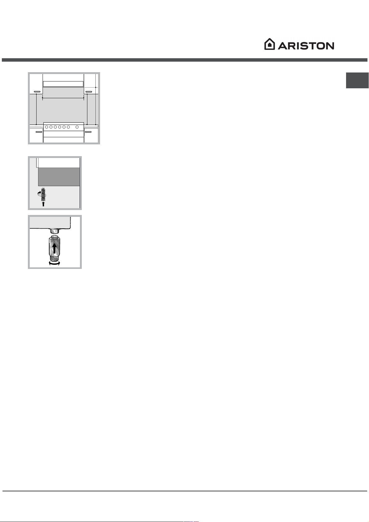
If the top of the hob is higher than the cupboards,
the appliance must be installed at least 200 mm
away from them.
If the cooker is installed underneath a wall cabinet,
there must be a minimum distance of 420 mm
between this cabinet and the top of the hob.
This distance should be increased to 700 mm if the
wall cabinets are flammable (see figure).
3
Page 4
mm.
420
Min.
HOOD
Min. mm.
600
mm. with hood
420
650
Min. mm.
min.
Do not position blinds
behind the cooker or
less than 200 mm away
from its sides.
Any hoods must be
mm. without hood
installed according to
700
the instructions listed in
min.
the relevant operating
manual.
Once the appliance has been installed, the power
supply cable and the electrical socket must be
easily accessible.
The cable must not be bent or compressed.
The cable must be checked regularly and replaced
by authorised technicians only.
The manufacturer declines any liability should
these safety measures not be observed.
GB
Levelling
If it is necessary to level the
appliance, screw the
adjustable feet into the places
provided on each corner of the
base of the cooker (see
figure).
The legs* fit into the slots on
the underside of the base of
the cooker.
Electrical connections
Install a standardised plug corresponding to the
load indicated on the appliance data plate (see
Technical data table).
The appliance must be directly connected to the
mains using an omnipolar circuit-breaker with a
minimum contact opening of 3 mm installed between
the appliance and the mains. The circuit-breaker
must be suitable for the charge indicated and must
comply with NFC 15-100 regulations (the earthing
wire must not be interrupted by the circuit-breaker).
The supply cable must be positioned so that it does
not come into contact with temperatures higher than
50°C at any point.
Before connecting the appliance to the power
supply, make sure that:
The appliance is earthed and the plug is compliant
with the law.
The socket can withstand the maximum power of
the appliance, which is indicated by the data plate.
The voltage is in the range between the values
indicated on the data plate.
The socket is compatible with the plug of the
appliance. If the socket is incompatible with the
plug, ask an authorised technician to replace it.
Do not use extension cords or multiple sockets.
* Only available in certain models.
Gas connection
Connection to the gas network or to the gas cylinder
may be carried out using a flexible rubber or steel
hose, in accordance with current national legislation
and after making sure that the appliance is suited to
the type of gas with which it will be supplied (see
the rating sticker on the cover: if this is not the case
see below). When using liquid gas from a cylinder,
install a pressure regulator which complies with
current national regulations. To make connection
easier, the gas supply may be turned sideways*:
reverse the position of the hose holder with that of
the cap and replace the gasket that is supplied with
the appliance.
Check that the pressure of the gas supply is consistent
with the values indicated in the Table of burner and
nozzle specifications (see below). This will ensure the
safe operation and durability of your appliance while
maintaining efficient energy consumption.
Gas connection using a flexible rubber hose
Make sure that the hose complies with current
national legislation. The internal diameter of the hose
must measure: 8 mm for liquid gas supply; 13 mm
for methane gas supply.
Once the connection has been performed, make
sure that the hose:
Does not come into contact with any parts that
reach temperatures of over 50°C.
Is not subject to any pulling or twisting forces and
that it is not kinked or bent.
Does not come into contact with blades, sharp
corners or moving parts and that it is not
compressed.
Is easy to inspect along its whole length so that
its condition may be checked.
Is shorter than 1500 mm.
Fits firmly into place at both ends, where it will be
fixed using clamps that comply with current
regulations.
4
Page 5
GB
If one or more of these conditions is not fulfilled or
if the cooker must be installed according to the
conditions listed for class 2 - subclass 1 appliances
(installed between two cupboards), the flexible steel
hose must be used instead (see below).
Connecting a flexible jointless stainless steel
pipe to a threaded attachment
Make sure that the hose and gaskets comply with
current national legislation.
To begin using the hose, remove the hose holder on
the appliance (the gas supply inlet on the appliance
is a cylindrical threaded 1/2 gas male attachment).
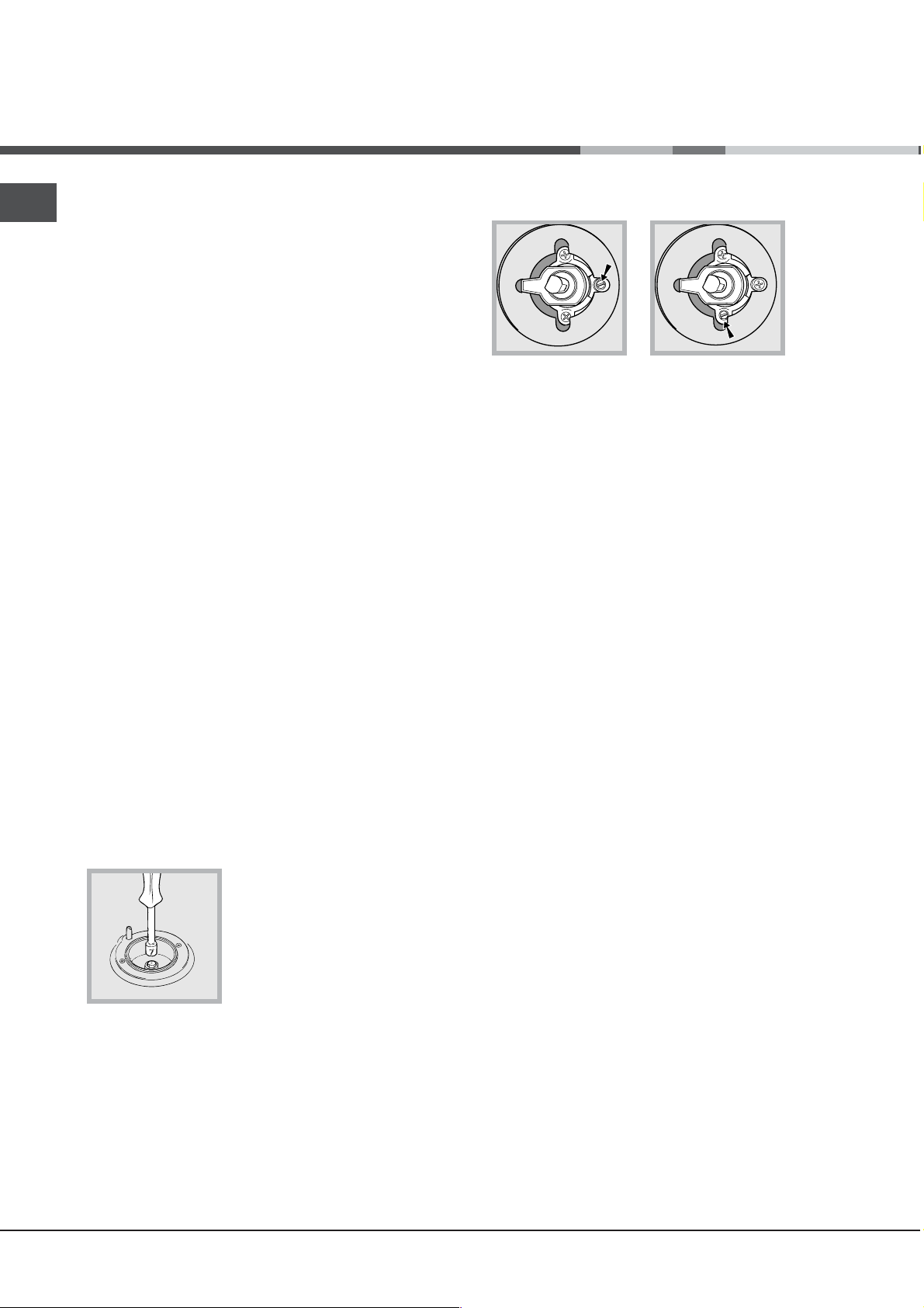
In the case of natural gas, the adjustment screw
must be unscrewed by turning it anti-clockwise.
3. While the burner is alight, quickly change the position
of the knob from minimum to maximum and vice versa
several times, checking that the flame is not
extinguished.
Perform the connection in such a way that the hose
length does not exceed a maximum of 2 metres,
making sure that the hose is not compressed and
does not come into contact with moving parts.
Checking the connection for leaks
When the installation process is complete, check
the hose fittings for leaks using a soapy solution.
Never use a flame.
Adapting to different types of gas
It is possible to adapt the appliance to a type of gas
other than the default type (this is indicated on the
rating label on the cover).
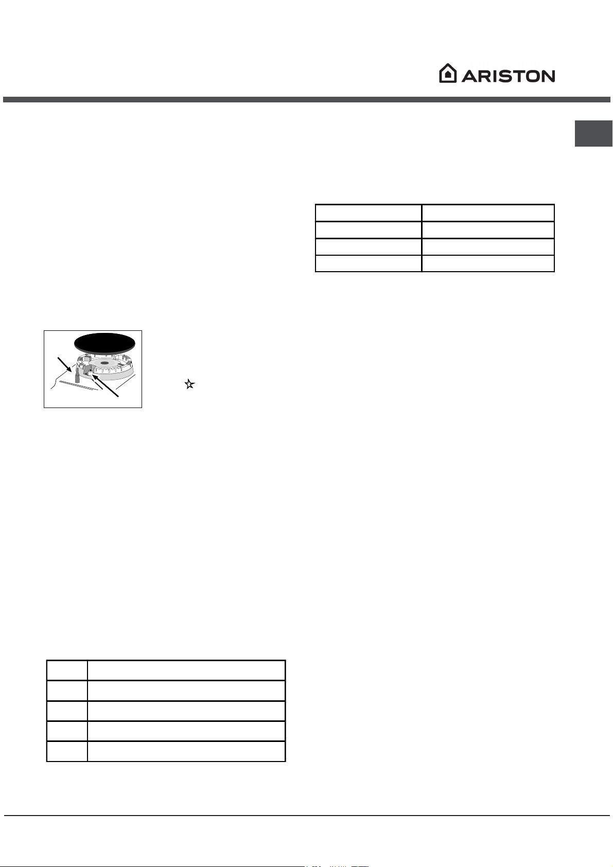
Adapting the hob
Replacing the nozzles for the hob burners:
1. Remove the hob grids and slide the burners off
their seats.
2. Unscrew the nozzles using
a 7 mm socket spanner (see
figure), and replace them with
nozzles suited to the new type
of gas (see Burner and nozzle
specifications table).
3. Replace all the components
by following the above instructions in reverse.
The hob burners do not require primary air adjustment.
After adjusting the appliance so it may be used
with a different type of gas, replace the old rating
label with a new one that corresponds to the new
type of gas (these labels are available from
Authorised Technical Assistance Centres).
Should the gas pressure used be different (or vary
slightly) from the recommended pressure, a suitable
pressure regulator must be fitted to the inlet hose in
accordance with current national regulations relating
to regulators for channelled gas.
Adjusting the hob burners minimum setting:
1. Turn the tap to the minimum position.
2. Remove the knob and adjust the regulatory
screw, which is positioned inside or next to the tap
pin, until the flame is small but steady.
5
Page 6
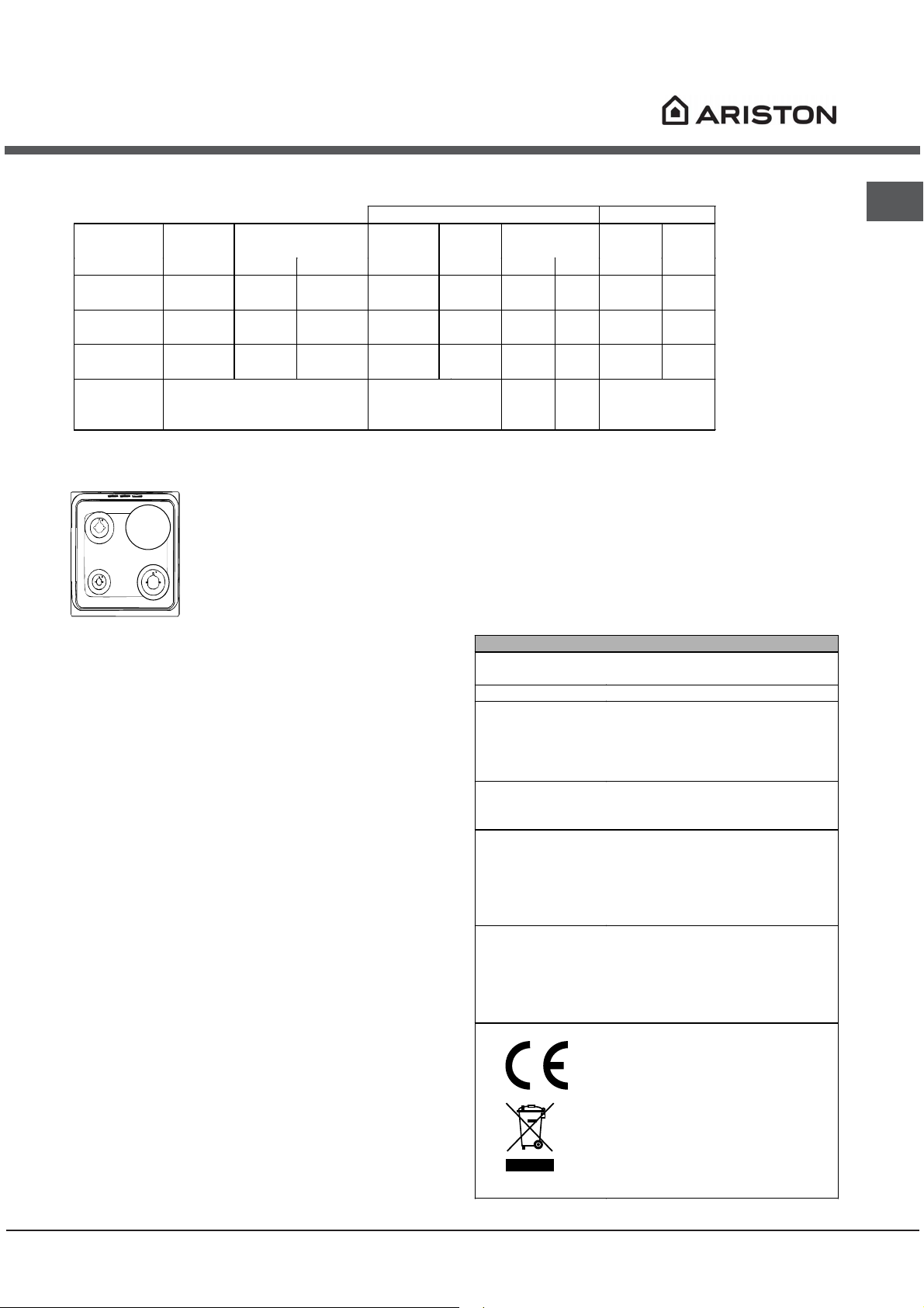
Table of burner and nozzle specifications
Table 1 Liquid Gas Natural Gas
Burner
Diameter
(mm)
Nominal Reduced (mm) (mm) *** ** (mm)
Fast
(Large)(R)
Semi Fast
(Medium)(S)
Auxiliary
(Small)(A)
100 3.00 0.7 41 87 218 214 128 286
75 1.90 0.4 30 70 138 136 104 181
51 1.00 0.4 30 52 73 71 76 95
Supply
Pressures
* At 15°C 1013 mbar-dry gas *** Butane P.C.S. = 49,47 MJ/Kg
** Propane P.C.S. = 50,37 MJ/Kg Natural P.C.S. = 37,78 MJ/m³
Ø180
S
R
A
Thermal Power
kW (p.c.s.*)
Nominal (mbar)
Minimum (mbar)
Maximum (mbar)
By Pass
1/100
Nozzle
1/100
Flow*
28-30
20
35
g/h
37
25
45
Nozzle
1/100
20
17
25
GB
Flow*
l/h
C 31 N1 EX
C 31S N1 EX
S
S
TECHNICAL DATA
Oven dimensions
(HxWxD)
Volume
Useful
measurements
relating to the
oven
compartment
Power supply
voltage and
frequency
Burners
ENERGY LABEL
34x39x44 cm
60 l
width 42 cm
depth 44 cm
height 17 cm
see data plate
may be adapted for use with any
type of gas shown on the data
plate, which is located inside the
flap or, after the oven compartment
has been opened, on the left-hand
wall inside the oven.
Directive 2002/40/EC on the label
of electric ovens. Standard EN
50304
Declared energy consumption for
Natural convection Class – heating
=
mode:
EC Directives: 73/23/EEC dated
19/02/73 (Low Voltage) and
subsequent amendments 89/336/EEC dated 03/05/89
(Electromagnetic Compatibility) and
subsequent amendments 90/369/EEC dated 29/06/90 (Gas)
and subsequent amendments 93/68/EEC dated 22/07/93 and
subsequent amendments 2002/96/EC.
Static
6
Page 7
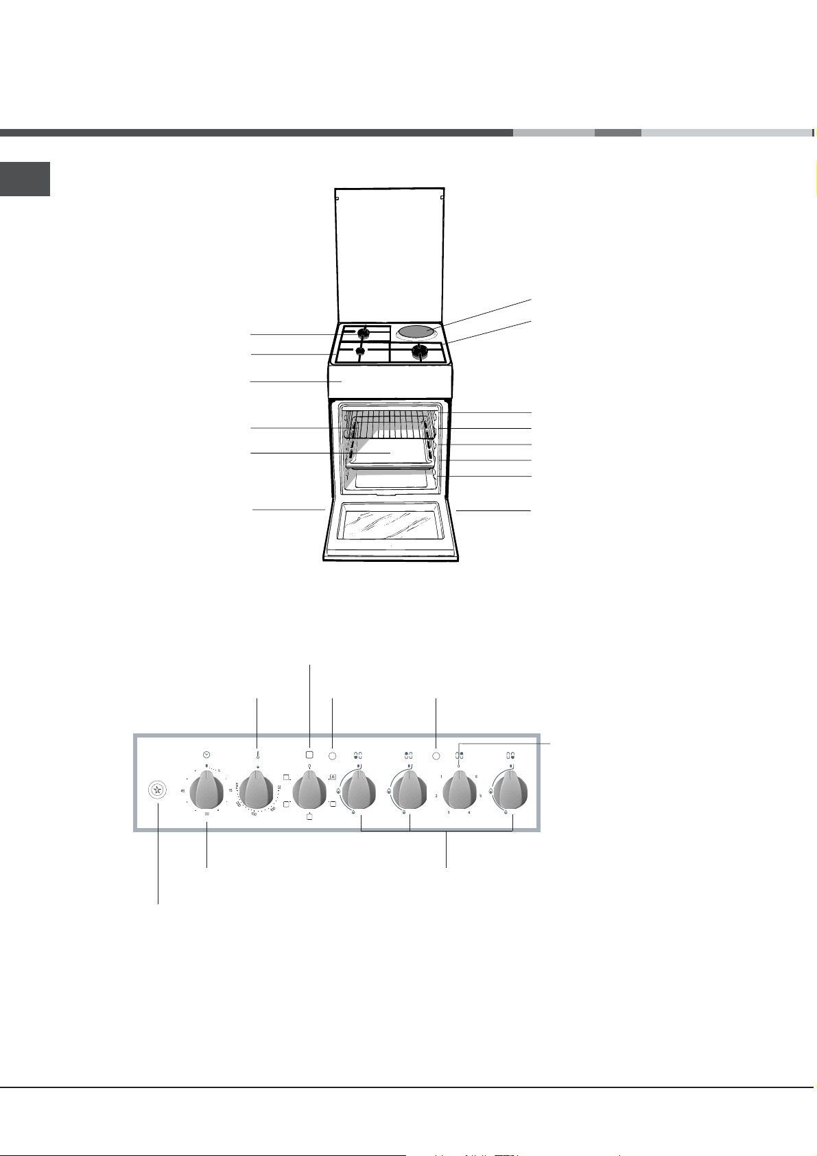
Description of the appliance
GB
Overall view
DRIPPING PAN
Adjustable foot
Gas burner
Hob grid
Control panel
GRILL
ELECTRIC HOTPLATE
Containment surface
for spills
GUIDE RAILS
for the sliding racks
position 5
position 4
position 3
position 2
position 1
Adjustable foot
Control panel
THERMOSTAT
GAS BURNER
ignition button*
SELECTOR
knob
TIMER
knob*
Knob
THERMOSTAT
indicator light
ACTIVE HOTPLATE
indicator light
ELECTRIC HOTPLATE
control knob
Hob BURNER
control knobs
Only available in certain models.
*
7
Page 8
Start-up and use
Using the hob
Lighting the burners
For each BURNER knob there is a complete ring
showing the strength of the flame for the relevant
burner.
To light one of the burners on the hob:
1. Bring a flame or gas lighter close to the burner.
2. Press the BURNER knob and turn it in an
anticlockwise direction so that it is pointing to the
maximum flame setting -.
3. Adjust the intensity of the flame to the desired
level by turning the BURNER knob in an
anticlockwise direction. This may be the minimum
setting +, the maximum setting - or any position in
between the two.
If the appliance is fitted with
X
setting, until the burner is lit. The burner may be
extinguished when the knob is released. If this
occurs, repeat the operation, holding the knob down
for a longer period of time.
If the flame is accidentally extinguished, switch off
the burner and wait for at least 1 minute before
attempting to relight it.
If the appliance is equipped with a flame failure
safety device*(X), press and hold the BURNER knob
for approximately 2-3 seconds to keep the flame
alight and to activate the device.
To switch the burner off, turn the knob until it
reaches the stop position .
Electric hotplates
The corresponding knob may be turned clockwise or
anti-clockwise and set to any of the six different
positions:
Setting Normal or Fast Plate
0
Off
1
Low
2 - 5
When the selector knob is in any position other than
the off position, the on light is illuminated.
6
Medium
High
an electronic lighting device*
( , press the ignition
)
D
button, marked with the
symbol
BURNER knob down and turn
D
it in an anticlockwise direction,
towards the maximum flame
, then hold the
Practical advice on using the burners
For the burners to work in the most efficient way
possible and to save on the amount of gas
consumed, it is recommended that only pans that
have a lid and a flat base are used. They should
also be suited to the size of the burner.
Burner ø Cookware diameter (cm)
Fast (R) 24 - 26
Semi Fast (S) 16 - 20
Auxiliary (A) 10 - 14
To identify the type of burner, please refer to the
diagrams contained in the Burner and nozzle
specifications.
Using the oven
The first time you use your appliance, heat the
empty oven with its door closed at its maximum
temperature for at least half an hour. Ensure that the
room is well ventilated before switching the oven off
and opening the oven door. The appliance may emit
a slightly unpleasant odour caused by protective
substances used during the manufacturing process
burning away.
Before operating the product, remove all plastic
film from the sides of the appliance.
1. Select the desired cooking mode by turning the
SELECTOR knob.
2. Select the recommended temperature for the
cooking mode or the desired temperature by turning
the THERMOSTAT knob.
A list detailing cooking modes and suggested
cooking temperatures can be found in the relevant
table (see Oven cooking advice table).
During cooking it is always possible to:
Change the cooking mode by turning the
SELECTOR knob.
Change the temperature by turning the
THERMOSTAT knob.
Set the total cooking time and the cooking end
time (see below).
Stop cooking by turning the SELECTOR knob to
the 0 position.
Never put objects directly on the bottom of the
oven; this will avoid the enamel coating being
damaged.
Always place cookware on the rack(s) provided.
Only available in certain models.
*
GB
8
Page 9
GB
THERMOSTAT indicator light
When this is illuminated, the oven is generating
heat. It switches off when the inside of the oven
reaches the selected temperature. At this point the
light illuminates and switches off alternately,
indicating that the thermostat is working and is
maintaining the temperature at a constant level.
Oven light
This is switched on by turning the SELECTOR knob
to any position other than 0. It remains lit as long
as the oven is operating. By selecting
knob, the light is switched on without any of the
heating elements being activated.
with the
&
Cooking modes
A temperature value can be set for all cooking
modes between 50°C and MAX, except for the
GRILL programme, for which only the MAX power
level is recommended.
STATIC OVEN mode
=
Both the top and bottom heating elements will come
on. When using this traditional cooking mode, it is
best to use one cooking rack only. if more than one
rack is used, the heat will be distributed unevenly.
OVEN BOTTOM mode
O
The lower heating element is activated. This position
is recommended for perfecting the cooking of
dishes (in baking trays) which are already cooked on
the surface but require further cooking in the centre,
or for desserts with a covering of fruit or jam, which
only require moderate colouring on the surface. It
should be noted that this function does not allow the
maximum temperature to be reached inside the oven
(250°C) and it is therefore not recommended that
foods are cooked using only this setting, unless you
are baking cakes (which should be baked at a
temperature of 180°C or lower).
GRILL mode
?
The top heating element is activated. The extremely
high and direct temperature of the grill makes it
possible to brown the surface of meats and roasts
while locking in the juices to keep them tender.
@
DOUBLE GRILL mode
The top heating element is activated. The grill is also
highly recommended for dishes that require a high
surface temperature: beef steaks, veal, rib steak,
fillets, hamburgers etc...
The GRILL and DOUBLE GRILL cooking modes must
be performed with the oven door shut.
Timer*
To activate the Timer proceed as follows:
1. Turn the TIMER knob in a clockwise direction "
for almost one complete revolution to set the buzzer.
2. Turn the TIMER knob in an anticlockwise direction
# to set the desired length of time.
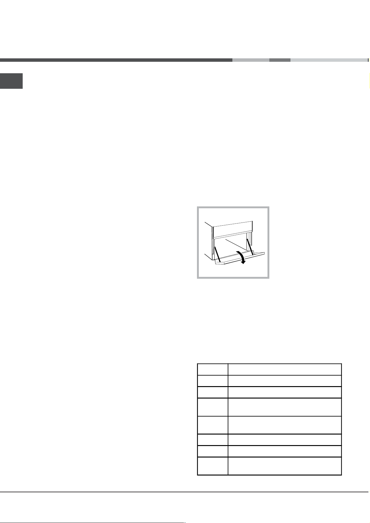
Lower compartment*
There is a compartment
underneath the oven
that may be used to
store oven accessories
or deep dishes. To open
the door pull it
downwards (see
figure).
Do not place flammable materials in the lower oven
compartment.
The internal surfaces of the compartment (where
present) may become hot.
Practical advice on using the electric
hotplates
To avoid heat loss and damage to the hotplates use
pans with a flat base, whose diameter is no less
than that of the hotplate itself.
Setting Normal or Fast Plate
0
Off
1
Cooking vegetables, fish
Cooking potatoes (using steam) soups,
2
chickpeas, beans.
Continuing the cooking of large quantities
3
of food, minestrone
4
For roasting (average)
5
For roasting (above average)
For browning and reaching a boil in a
6
short time.
9
Page 10
Before using the hotplates for the first time, you
should heat them at maximum temperature for
approximately 4 minutes, without placing any pans
on them. During this initial stage, their protective
coating hardens and reaches its maximum
resistance.
Practical cooking advice
In the GRILL cooking mode, place the dripping
pan in position 1 to collect cooking residues (fat
and/or grease).
GRILL
Insert the rack in position 3 or 4. Place the food in
the centre of the rack.
We recommend that the power level is set to
maximum. The top heating element is regulated
by a thermostat and may not always operate
constantly.
PIZZA
Use a light aluminium pizza pan. Place it on the
rack provided.
For a crispy crust, do not use the dripping pan as
it prevents the crust from forming by extending
the total cooking time.
If the pizza has a lot of toppings, we recommend
adding the mozzarella cheese on top of the pizza
halfway through the cooking process.
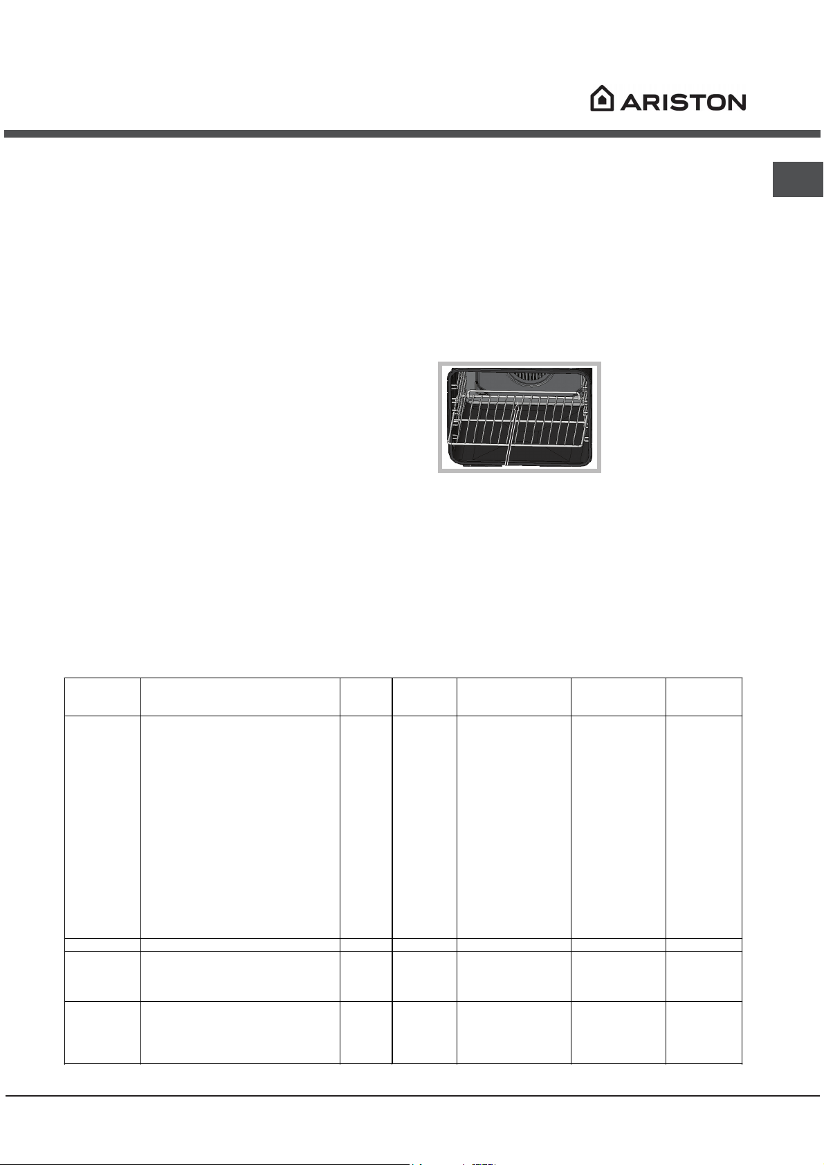
!!
When inserting theWhen inserting the
!
When inserting the
!!
When inserting theWhen inserting the
shelf make sure theshelf make sure the
shelf make sure the
shelf make sure theshelf make sure the
backstop is at the rearbackstop is at the rear
backstop is at the rear
backstop is at the rearbackstop is at the rear
of the cavity (seeof the cavity (see
of the cavity (see
of the cavity (seeof the cavity (see
image)image)
image)
image)image)
GB
Oven cooking advice table
Cooking
modes
Static
Oven bottom
Grill
Double Grill
Lasagne
Cannelloni
Baked pasta
Veal
Chicken
Duck
Rabbit
Pork
Lamb
Mackerel
Mackerel
Trout baked in foil
Neapolitan-style pizza
Biscuits and small cakes
Sweet unleavened flans and desserts
Savoury pies
Leavened cakes
Fruit cakes
Perfecting cooking
Sole and cuttlefish
Squid and prawn kebabs
Cod fillet
Grilled vegetables
Veal steak
Chops
Hamburgers
Mackerel
Toast
Foods Weight
(in kg)
2.5
2.5
2.0
1.7
1.5
1.8
2
2.1
1.8
1.1
1.5
1
1
0.5
1.1
1
0.5
1
1
1
1
1
1
1.5
1
1
4 pcs
Rack
position
2
3
3
2
3
3
3
3
3
2
2
2
2
3
3
3
3
3
4
4
4
3/4
4
4
3
4
4
Preheating time
(min)
5
5
5
10
10
10
10
10
10
5
5
5
15
10
10
10
10
10
5
5
5
5
5
5
5
5
5
Recommended
Temperature
(°C)
200
200
200
180
200
180
180
180
180
180
180
180
220
180
180
180
160
170
Max
Max
Max
Max
Max
Max
Max
Max
Max
Cooking
time
(minutes)
45-50
30-35
30-35
60-70
80-90
90-100
70-80
70-80
70-80
30-40
30-35
25-30
15-20
10-15
25-30
30-35
25-30
25-30
8
4
10
8-10
15-20
20
7
15-20
5
10
Page 11

Precautions and tips
GB
! The appliance was designed and manufactured in
compliance with international safety standards.
The following warnings are provided for safety
reasons and must be read carefully.
General safety
These instructions are only valid for the countries
whose symbols appear in the manual and on the
serial number plate.
The appliance was designed for domestic use
inside the home and is not intended for
commercial or industrial use.
The appliance must not be installed outdoors,
even in covered areas. It is extremely dangerous
to leave the appliance exposed to rain and
storms.
Do not touch the appliance with bare feet or with
wet or damp hands and feet.
The appliance must be used by adults only for the
preparation of food, in accordance with the
instructions provided in this booklet (the
instructions apply to all countries listed at the
beginning of the booklet).
The instruction booklet accompanies a class 1
(insulated) or class 2 - subclass 1 (recessed
between 2 cupboards) appliance.
Keep children away from the oven.
Make sure that the power supply cables of other
electrical appliances do not come into contact
with the hot parts of the oven.
The openings used for the ventilation and
dispersion of heat must never be covered.
Do not close the glass hob cover (selected
models only) when the burners are alight or when
they are still hot.
Always use oven gloves when placing cookware
in the oven or when removing it.
Do not use flammable liquids (alcohol, petrol,
etc...) near the appliance while it is in use.
Do not place flammable material in the lower
storage compartment or in the oven itself. If the
appliance is switched on accidentally, it could
catch fire.
Always make sure the knobs are in the position
and that the gas tap is closed when the appliance
is not in use.
When unplugging the appliance, always pull the
plug from the mains socket; do not pull on the
cable.
Never perform any cleaning or maintenance work
without having disconnected the appliance from
the electricity mains.
If the appliance breaks down, under no
circumstances should you attempt to repair the
appliance yourself. Repairs carried out by
inexperienced persons may cause injury or further
malfunctioning of the appliance. Contact
Assistance.
Do not rest heavy objects on the open oven door.
Disposal
When disposing of packaging material: observe
local legislation so that the packaging may be
reused.
The European Directive 2002/96/EC relating to
Waste Electrical and Electronic Equipment
(WEEE) states that household appliances should
not be disposed of using the normal solid urban
waste cycle. Exhausted appliances should be
collected separately in order to optimise the cost
of re-using and recycling the materials inside the
machine, while preventing potential damage to
the atmosphere and to public health. The
crossed-out dustbin is marked on all products to
remind the owner of their obligations regarding
separated waste collection.
Exhausted appliances may be collected by the
public waste collection service, taken to suitable
collection areas in the area or, if permitted by
current national legislation, they may be returned
to the dealers as part of an exchange deal for a
new equivalent product.
All major manufacturers of household appliances
participate in the creation and organisation of
systems for the collection and disposal of old and
disused appliances.
Respecting and conserving the
environment
You can help to reduce the peak load of the
electricity supply network companies by using the
oven in the hours between late afternoon and the
early hours of the morning.
Always keep the oven door closed when using the
GRILL and DOUBLE GRILL modes. This will
achieve better results while saving energy
(approximately 10%).
Check the door seals regularly and wipe them
clean to ensure they are free of debris so that
they adhere properly to the door, thus avoiding
heat dispersion.
11
Page 12

Care and maintenance
Switching the appliance off
Disconnect your appliance from the electricity
supply before carrying out any work on it.
Cleaning the appliance
Do not use abrasive or corrosive detergents such
as stain removers, anti-rust products, powder
detergents or sponges with abrasive surfaces: these
may scratch the surface beyond repair.
Never use steam cleaners or pressure cleaners on
the appliance.
It is usually sufficient simply to wash the hob
using a damp sponge and dry it with absorbent
kitchen roll.
The stainless steel or enamel-coated external
parts and the rubber seals may be cleaned using
a sponge that has been soaked in lukewarm water
and neutral soap. Use specialised products for
the removal of stubborn stains. After cleaning,
rinse well and dry thoroughly. Do not use abrasive
powders or corrosive substances.
The hob grids, burner caps, flame spreader rings
and burners may be removed to make cleaning
easier; wash them in hot water and non-abrasive
detergent, making sure all burnt-on residue is
removed before drying them thoroughly.
For hobs with electronic ignition, the terminal part
of the electronic lighting devices should be
cleaned frequently and the gas outlet holes
should be checked for blockages.
The inside of the oven should ideally be cleaned
after each use, while it is still lukewarm. Use hot
water and detergent, then rinse well and dry with
a soft cloth. Do not use abrasive products.
Stainless steel can be marked by hard water that
has been left on the surface for a long time, or by
aggressive detergents containing phosphorus.
After cleaning, rinse well and dry thoroughly. Any
remaining drops of water should also be dried.
Do not close the cover when the burners are alight
or when they are still hot.
Inspecting the oven seals
Check the door seals around the oven regularly. If
the seals are damaged, please contact your nearest
Authorised After-sales Service Centre. We
recommend that the oven is not used until the seals
have been replaced.
Gas tap maintenance
Over time, the taps may become jammed or difficult
to turn. If this occurs, the tap must be replaced.
This procedure must be performed by a qualified
technician authorised by the manufacturer.
Replacing the oven light bulb
1. After disconnecting the
oven from the electricity
mains, remove the glass lid
covering the lamp socket (see
figure).
2. Remove the light bulb and
replace it with a similar one:
voltage 230 V, wattage 25 W,
cap E 14.
3. Replace the lid and reconnect the oven to the
electricity supply.
! Do not use the oven lamp as/for ambient
lighting.
GB
Clean the glass part of the oven door using a
sponge and a non-abrasive cleaning product,
then dry thoroughly with a soft cloth. Do not use
rough abrasive material or sharp metal scrapers
as these could scratch the surface and cause the
glass to crack.
The accessories can be washed like everyday
crockery, and are even dishwasher safe.
12
Assistance
Please have the following information to hand:
The appliance model (Mod.).
The serial number (S/N).
This information can be found on the data plate
located on the appliance and/or on the packaging.
Page 13

Mode demploi
CUISINIERE
FR
GB FR
English, 1 Français,
C 31 N1 EX
C 31S N1 EX
SSS
SSS
13
AR
Sommaire
ATTNENTIONATTNENTIONATTNENTION
Installation,
Positionnement et nivellement
Raccordement électrique
Raccordement gaz
Adaptation aux différents types de gaz
Données techniques
Tableau Caractéristiques des brûleurs et des
injecteurs
Description de lappareil,
Vue densemble
Tableau de bord
Mise en marche et utilisation,
Utilisation du plan de cuisson
Utilisation du four
Quelques conseils utiles pour bien utiliser votre
plaque électrique
Conseils de cuisson
Tableau de cuisson au four
,14
,15-18
,19
20-22
Précautions et conseils,
Sécurité générale
Mise au rebut
Economies et respect de lenvironnement
Nettoyage et entretien,
Mise hors tension
Nettoyage de lappareil
Entretien robinets gaz
Remplacement de lampoule déclairage du four
Assistance
23
24
Page 14

ATTENTION
FR
ATTENTION : cet appareil ainsi
que ses parties accessibles
deviennent très chauds pendant leur
fonctionnement.
Il faut faire attention de ne pas
toucher les éléments chauffants.
Ne laisser s’approcher les enfants
de moins de 8 ans à moins qu’ils ne
soient sous surveillance constante.
Le présent appareil peut être utilisé
par des enfants de plus de 8 ans et
par des personnes présentant des
capacités physiques, sensorielles
ou mentales réduites ou n’ayant pas
l’expérience ou les connaissances
nécessaires, à condition qu’ils
soient sous bonne surveillance ou
qu’ils aient reçu les instructions
nécessaires pour une utilisation
de l’appareil en toute sécurité et à
condition qu’ils se rendent compte
des dangers encourus. Les enfants
ne doivent pas jouer avec l’appareil.
Les opérations de nettoyage et
d’entretien ne doivent pas être
effectuées par des enfants non
surveillés.
ATTENTION : laisser un récipient de
cuisson contenant de l’huile ou de la
graisse sur le foyer est dange
Ne pas utiliser de produits abrasifs ni
de spatules métalliques coupantes
pour nettoyer la porte du four en
verre, sous peine d’érafler la surface
et de briser le verre.
Les surfaces intérieures du tiroir (s’il
y en a un) peuvent devenir chaudes.
Ne jamais nettoyer l’appareil avec
des nettoyeurs vapeur ou haute
pression.
Essuyer tout liquide pouvant se
trouver sur le couvercle avant de
l’ouvrir. Ne pas abaisser le couvercle
en verre (s’il y en a un) tant que les
brûleurs gaz ou la plaque électrique
sont chauds.
ATTENTION : s’assurer que l’appareil
est éteint avant de procéder au
remplacement de l’ampoule, afin
d’éviter tout risque d’électrocution.
ATTENTION : si la table en verre
est endommagée :- éteindre
immédiatement tous les brûleurs et
les éventuels éléments chauffants
électriques et débrancher l’appareil
du réseau électrique
Il ne faut JAMAIS essayer d’éteindre
une flamme ou un incendie avec de
l’eau ! Il faut éteindre l’appareil et
couvrir la flamme avec un couvercle,
par exemple, ou avec une couverture
anti-feu.
14
Page 15

Installation
Conserver ce mode demploi pour pouvoir le
consulter tout moment. En cas de vente, de cession
ou de déménagement, veiller à ce quil suive
lappareil.
Lire attentivement les instructions : elles
contiennent des conseils importants sur linstallation,
lutilisation et la sécurité de lappareil
Linstallation de lappareil doit être effectuée par un
professionnel du secteur conformément aux
instructions du fabricant.
Nimporte quelle opération de réglage, dentretien
ou autre, doit être effectuée après avoir débranché
la prise de la cuisinière.
Conditions réglementaires dinstallation
Le raccordement gaz devra être fait par un
professionnel qualifié qui assurera la bonne
alimentation en gaz et le meilleur réglage de la
combustion des brûleurs. Ces opérations
dinstallation, quoique simples, sont délicates et
primordiales pour que votre cuisinière vous rende le
meilleur service. Linstallation doit être effectuée
conformément aux textes réglementaires et règles
de lart en vigueur, notamment:
Arrêté du 2 août 1977. Règles techniques et de
sécurité applicables aux installations de gaz
combustibles et dhydro-carbures liquéfiés
situées à lintérieur des bâtiments dhabitation et
de leur dépendances.
Norme DTU P45-204. Installations de gaz
(anciennement DTU n° 61-1-installations de gaz Avril 1982 + additif n°1 Juillet 1984).
Règlement sanitaire départemental.
dépourvus du dispositif de sécurité de flamme et
quand lafflux de lair provient de manière indirecte
de pièces voisines (voir figure B) à condition quil
ne sagisse pas de parties communes du bâtiment,
de chambres à coucher ou de locaux à risque
dincendie équipées dun conduit daération avec
lextérieur comme décrit plus haut.
A
A
Ouverture de
ventilation pour lair
comburant
B
Local adjacent Local à ventiler
Agrandissement de la
fissure entre la porte et le
sol
Après une utilisation prolongée de lappareil, il est
conseillé douvrir une fenêtre ou daugmenter la
vitesse de ventilateurs éventuels.
Evacuation des fumées de combustion
La pièce doit prévoir un système dévacuation vers
lextérieur des fumées de combustion réalisé au
moyen dune hotte reliée à une cheminée à tirage
naturel ou par ventilateur électrique qui entre
automatiquement en fonction dès quon allume
lappareil (voir figures).
FR
Aération des locaux
Lappareil doit être installé dans des locaux qui sont
aérés en permanence, selon les prescriptions des
Normes en vigueur dans le pays dinstallation. Il est
indispensable que la pièce où lappareil est installé
dispose dune quantité dair égale à la quantité dair
comburant nécessaire à une bonne combustion du
gaz (le flux dair doit être dau moins 3 m
3
/h par kW
de puissance installée).
Les prises dair, protégées par des grilles, doivent
disposer dun conduit dau moins 100 cm
2
de
section utile et dans une position qui leur évite tout
risque dêtre bouchées accidentellement, même
partiellement (voir figure A).
Ces ouvertures doivent être agrandies de 100%
(surface minimale 200 cm
2
) en cas dappareils
Evacuation directement
à lextérieur
Evacuation par cheminée
ou conduit de fumée
ramifié (réservé aux
appareils de cuisson)
Les gaz de pétrole liquéfiés, plus lourds que lair,
se déposent et stagnent dans le bas. Les locaux qui
contiennent des bouteilles de G.P.L doivent donc
prévoir des ouvertures vers lextérieur afin de
permettre lévacuation du gaz par le bas en cas de
fuites accidentelles.
Ne pas installer ou entreposer de bouteilles de GPL,
vides ou partiellement pleines, dans des locaux qui
se trouvent en sous-sol (caves etc.). Ne garder dans
la pièce que la bouteille en cours dutilisation, loin de
sources de chaleur (fours, feux de bois, poêles etc.)
qui pourraient amener sa température à plus de 50°C.
15
Page 16

FR
Positionnement et nivellement
Lappareil peut être installé à côté de meubles dont
la hauteur ne dépasse pas celle du plan de cuisson.
Sassurer que le mur en contact avec la paroi
arrière de lappareil est réalisé en matériel ignifuge
résistant à la chaleur (T 90°C).
Pour une installation correcte :
installer cet appareil dans une cuisine, une salle à
manger ou un studio (jamais dans une salle de
bains) ;
si le plan de cuisson de la cuisinière dépasse le
plan de travail des meubles, ces derniers doivent
être placés à au moins 200 mm de lappareil.
si la cuisinière est
HOOD
Min. mm.
600
mm.
420
Min.
420
Min. mm.
ne pas placer de rideaux derrière ou sur les côtés
de la cuisinière à moins de 200 mm de distance.
pour linstallation de hottes, se conformer aux
instructions de leur notice demploi.
installée sous un élément
suspendu, il faut que ce
dernier soit placé à au
moins 420 mm de
distance du plan. Il faut
mm. with hood
mm. without hood
650
700
prévoir une distance de
min.
min.
700 mm si les éléments
suspendus sont
inflammables (voir
figure);
intercaler entre lappareil et le réseau un interrupteur à
coupure omnipolaire ayant au moins 3 mm décartement
entre les contacts, dimensionné à la charge et conforme
aux normes NFC 15-100 (le fil de terre ne doit pas être
interrompu par linterrupteur). Le câble dalimentation ne
doit atteindre, en aucun point, une température
dépassant de 50°C la température ambiante.
Avant de procéder au branchement, sassurer que :
la prise est bien munie dune terre conforme à la loi;
la prise est bien apte à supporter la puissance
maximale de lappareil, indiquée sur la plaque
signalétique;
la tension dalimentation est bien comprise entre
les valeurs indiquées sur la plaque signalétique;
la prise est bien compatible avec la fiche de
lappareil. Si ce nest pas le cas, remplacer la
prise ou la fiche, ne pas utiliser de rallonges ni de
prises multiples.
Après installation de lappareil, le câble électrique
et la prise de courant doivent être facilement
accessibles
Le câble ne doit être ni plié ni excessivement
écrasé.
Le câble doit être contrôlé périodiquement et ne
peut être remplacé que par un technicien agréé.
Nous déclinons toute responsabilité en cas de
non respect des normes énumérées ci-dessus.
Nivellement
Pour mettre lappareil bien à
plat, visser les pieds de
réglage fournis aux
emplacements prévus aux
coins à la base de la
cuisinière (voir figure).
Montage des pieds* par
encastrement sous la base.
Raccordement électrique
Monter sur le câble une prise normalisée pour la
charge indiquée sur létiquette des caractéristiques
(voir tableau des caractéristiques techniques).
En cas de raccordement direct au réseau, il faut
Raccordement gaz
Pour raccorder lappareil au réseau de distribution
du gaz ou à la bouteille de gaz utiliser un tuyau
flexible en caoutchouc ou en acier, conformément à
la réglementation en vigueur. Sassurer auparavant
que lappareil est bien réglé pour le type de gaz
dalimentation utilisé (voir étiquette sur le couvercle :
autrement voir ci-dessous). Si lalimentation
seffectue avec du gaz liquide en bouteille, utiliser
des régulateurs de pression conformes à la
réglementation en vigueur dans le pays. Pour
simplifier le raccordement, lalimentation du gaz est
orientable latéralement* : inverser labout annelé
avec le bouchon de fermeture et remplacer le joint
détanchéité (fourni avec lappareil).
Pour un fonctionnement en toute sécurité, pour un
meilleur emploi de lénergie et une plus longue durée
de vie de lappareil, vérifier que la pression
dalimentation respecte bien les valeurs indiquées
dans le tableau Caractéristiques des brûleurs et des
injecteurs (voir ci-dessous).
* Nexiste que sur certains modèles
16
Page 17

Raccordement gaz par tuyau flexible en
caoutchouc
Sassurer que le tuyau est bien conforme aux
normes applicables dans le pays dinstallation. Le
tuyau doit avoir un diamètre intérieur de : 8 mm en
cas dalimentation au gaz liquide; 15 mm en cas
dalimentation au gaz naturel.
Après avoir effectué le raccordement, sassurer que
le tuyau :
ne touche en aucun point à des parties pouvant
atteindre plus de 50°C;
nest pas soumis à traction ou torsion et ne
présente pas de pliures ou étranglements;
ne risque pas dentrer en contact avec des corps
tranchants, des arêtes vives, des parties mobiles
et nest pas écrasé;
est facilement contrôlable sur toute sa longueur
pour vérifier son état de conservation;
a moins de 1500 mm de long;
est bien fixé à ses deux extrémités à laide de
bagues de serrage conformes à la réglementation
en vigueur dans le pays.
Si une ou plusieurs de ces conditions ne peuvent
être remplies ou que la cuisinière est installée dans
des conditions de classe 2 sous-classe 1 (appareil
encastré entre deux meubles), il faut utiliser un
tuyau flexible en acier (voir ci-dessous).
Raccordement gaz par tuyau flexible en acier
inox, à paroi continue
Sassurer que le tuyau et les joints sont bien
conformes aux normes applicables dans le pays
dinstallation.
Pour installer le tuyau, enlever labout annelé
équipant lappareil (le raccord dentrée du gaz à
lappareil est fileté 1/2 gaz mâle cylindrique).
Procéder au raccordement de manière à ce que la
longueur du tuyau ne dépasse pas 2 mètres
dextension maximale. Veiller à ce que le tuyau ne
soit pas écrasé et ne touche en aucun point à des
parties mobiles.
avec raccords filetés
Adaptation aux différents types de gaz
FR
Lappareil peut être adapté à un type de gaz autre
que celui pour le quel il a été conçu (indiqué sur
létiquette de réglage sur le couvercle).
Adaptation du plan de cuisson
Remplacement des injecteurs des brûleurs du plan
de cuisson:
1. enlever les grilles du plan de cuisson et sortir les
brûleurs de leur logement;
2. dévisser les injecteurs à
laide dune clé à tube de 7
mm (voir figure) et les
remplacer par les injecteurs
adaptés au nouveau type de
gaz (voir tableau
Caractéristiques des brûleurs
et des injecteurs) ;
3. remonter les différentes parties en effectuant les
opérations dans le sens inverse.
Réglage des minima des brûleurs du plan de
cuisson :
1. placer le robinet sur la position minimum;
2. enlever le bouton et tourner la vis de réglage
positionnée à lintérieur ou sur le côté de la tige du
robinet jusquà obtenir une petite flamme régulière;
En cas de gaz naturel, il faut dévisser la vis de
réglage en tournant dans le sens inverse des
aiguilles dune montre;
3. vérifier si, en tournant rapidement le robinet du
maximum au minimum, le brûleur ne séteint pas.
Les brûleurs du plan de cuisson ne nécessitent
pas de réglage de lair primaire.
Après avoir procédé au réglage pour le nouveau
type de gaz, remplacer la vieille étiquette par celle
correspondant au nouveau gaz, disponible dans les
centres dassistance technique agréés.
Si la pression du gaz diffère (ou varie) par rapport
à la pression prévue, il faut installer, sur la tuyauterie
dentrée un régulateur de pression approprié
conforme à la réglementation sur les régulateurs
pour gaz canalisés en vigueur dans le pays.
Vérification de létanchéité
Une fois linstallation terminée, vérifier létanchéité
de tous les raccords en utilisant une solution
savonneuse, ne jamais utiliser de flamme.
17
Page 18

FR
Tableau Caractéristiques des brûleurs et des injecteurs
Tableau 1
Brûleur à gaz Diamètre
(mm)
Rapide
(Grand) (R)
100 3.00 0.70 41 87 218 214 128 286 332
Semi Rapide
(Intermédiaire)
75 1.90 0.40 30 70 138 136 104 181 210
(S)
Auxiliaire
(Petit) (A)
51 1.00 0.40 30 52 73 71 76 95 111
Pressions
d'alimentation
Puissance
thermique
By-pass
1/100
kW (p.c.s.*)
Nominale Réduite (mm) (mm) *** ** (mm) G20 G25
Nominale (mbar)
Minima (mbar)
Maxima (mbar)
Gaz liquide
injecteur
1/100
* A 15°C et 1013 mbar-gaz sec
** Propane P.C.S. = 50,37 MJ/Kg
*** Butane P.C.S. = 49,47 MJ/Kg
Naturel G20 P.C.S = 37,78 MJ/m
Naturel G25 P.C.S = 32,49 MJ/m
3
3
Charge*
28-30
20
35
g/h
37
25
45
injecteur
1/100
Gaz naturel
Charge*
20
17
25
l/h
25
20
30
Ø180
S
R
A
C 31 N1 EX
C 31S N1 EX
CARACTERISTIQUES TECHNIQUES
Dimensions du
four HxLxP
Volume
Dimensions utiles
S
SS
SSS
du tiroir chauffeplats
34x39x44 cm
l 60
largeur 42 cm
profondeur 44 cm
hauteur 17 cm
Tension et
fréquence
voir plaque signalétique
d’alimentation :
adaptables à n’importe quel type de
gaz parmi ceux indiqués sur
Brûleurs
l’étiquette collée à l’intérieur du
portillon ou sur la paroi intérieure
gauche (visible après avoir sorti le
tiroir chauffe-plats).
Directive 2002/40/CE sur l'étiquette
des fours électriques Norme EN
ETIQUETTE
ENERGIE
50304 Consommation d’énergie
déclaration Classe convection
Naturelle – fonction four :
=
Statique
Directives Communautaires:
73/23/CEE du 19/02/73 (Basse
Tension) et modifications
successives - 89/336/CEE du
03/05/89 (Compatibilité
Electromagnétique) et modifications
successives -90/369/CEE du
29/06/90 (Gaz) et modifications
successives 93/68/CEE du
22/07/93 et modifications
successives - 2002/96/EC.
18
Page 19

Description de lappareil
Vue densemble
Brûleur à gaz
Grille du plan de cuisson
FR
Plaque électrique
Plateau du plan
de cuisson
Tableau de bord
Support GRILLE
Support LECHEFRITE
Pied de réglage
Tableau de bord
THERMOSTAT
Bouton
PROGRAMMES
Bouton
Voyant
THERMOSTAT
GLISSIERES
de coulissement
niveau 5
niveau 4
niveau 3
niveau 2
niveau 1
Pied de réglage
Voyant
FONCTIONNEMENT PLAQUE
Bouton
PLAQUE ELECTRIQUE
Bouton
MINUTEUR*
Bougie d'allumage des
BRULEURS GAZ*
Nexiste que sur certains modèles
*
Boutons BRULEURS
du plan de cuisson
19
Page 20

Mise en marche et utilisation
FR
Utilisation du plan de cuisson
Allumage des brûleurs
Un petit cercle plein près de chaque bouton
BRULEUR indique le brûleur associé à ce dernier.
Pour allumer un brûleur du plan de cuisson:
1. approcher une flamme ou un allume-gaz ;
2. pousser sur le bouton du BRULEUR tout en le
tournant dans le sens inverse des aiguilles dune
montre jusquau symbole grande flamme -.
3. pour régler la puissance de la flamme souhaitée,
tourner le bouton BRULEUR dans le sens inverse
des aiguilles dune montre : sur la position minimum
+, sur la position maximum - ou sur une position
intermédiaire.
X
D
aiguilles dune montre le bouton BRULEUR pour
lamener en face du symbole grande flamme, jusquà
lallumage. Il peut arriver que le brûleur séteigne dès
quon lâche le bouton. Dans ce cas, tenter à nouveau en
poussant plus longtemps sur le bouton.
En cas dextinction accidentelle des flammes,
éteindre le brûleur et attendre au moins 1 minute
avant de tenter de rallumer.
Si l’appareil est équipé d’un dispositif de sécurité*X
de flamme, poussez sur le manette BRULEUR
pendant 2-3 secondes pour garder la flamme
allumée et pour activer le dispositif.
Pour éteindre le brûleur, tourner le bouton jusquà la
position darrêt .
Plaque électrique
Pour procéder au réglage, tourner la manette
correspondante dans le sens des aiguilles dune
montre ou dans le sens inverse en choisissant une
des 6 positions possibles :
Position Plaque normale ou rapide
0
Eteint
1
Poissance minimum
Si lappareil est équipé dun
allumage électronique* (
il faut dabord appuyer
sur la touche dallumage,
repérée par le symbole
correspondant, puis pousser à
fond et tourner en même temps
dans le sens inverse des
D)
Conseils pratiques pour lutilisation des brûleurs
Pour un meilleur rendement des brûleurs et une
moindre consommation de gaz, utiliser des
casseroles à fond plat, munies de couvercle et dun
diamètre adapté au brûleur :
Brûleur ø Diamètre récipients (cm)
Rapide (R) 24 – 26
Semi-Rapide (S) 16 – 20
Auxiliaire (A) 10 – 14
Pour repérer le type de brûleur adéquat, se référer
aux dessins du paragraphe Caractéristiques des
brûleurs et des injecteurs.
Utilisation du four
Lors de son premier allumage, faire fonctionner le
four à vide, porte fermée, pendant au moins une
heure en réglant la température à son maximum.
Puis éteindre le four, ouvrir la porte et aérer la pièce.
Lodeur qui se dégage est due à lévaporation des
produits utilisés pour protéger le four.
Avant toute utilisation, vous devez impérativement
enlever les films plastiques situés sur les côtés de
lappareil
1. Pour sélectionner le programme de cuisson
souhaité, tourner le bouton PROGRAMMES.
2. Choisir la température conseillée pour ce
programme ou celle quon préfère à laide du bouton
THERMOSTAT.
Un tableau de cuisson sert de guide et indique
notamment les températures conseillées pour
plusieurs préparations culinaires (voir tableau
cuisson au four).
En cours de cuisson, on peut à tout moment :
modifier le programme de cuisson à laide du
bouton PROGRAMMES;
modifier la température à laide du bouton
THERMOSTAT;
programmer la durée et lheure de fin de cuisson
(voir ci-dessous);
interrompre la cuisson en ramenant le bouton
PROGRAMMES sur 0.
2 - 5
Toute position de la manette autre que la position
éteint entraîne lallumage du voyant de
fonctionnement.
20
Poissance intermédiaires
6
Poissance maximum
Ne jamais poser dobjets à même la sole du four,
lémail risque de sabîmer.
Il faut toujours placer les plats sur la grille fournie
avec lappareil.
Nexiste que sur certains modèles
*
Page 21

Voyant THERMOSTAT
Allumé, il signale la montée en chaleur du four. Il
séteint dès que la température sélectionnée est
atteinte. Le voyant sallume et séteint tour à tour
pour indiquer que le thermostat fonctionne et
maintient la température au degré près.
Programme DOUBLE GRIL
@
La résistance de voûte est branchée. La cuisson au
gril est particulièrement recommandée pour les
plats qui exigent une température élevée à leur
surface : côtes de veau et de buf, entrecôtes,
filet, hamburgers, etc...
FR
Eclairage du four
Pour lallumer, amener le bouton PROGRAMMES sur
une position autre que la position 0. Il reste allumé
tant que le four est en marche. Si on tourne le
bouton sur
aucune résistance.
, la lampe sallume sans activer
&
Programmes de cuisson
Pour tous les programmes il est possible de
sélectionner une température comprise entre 50°C et
MAX., sauf pour le programme GRIL, pour lequel il
est préconisé de sélectionner MAX.
Programme FOUR STATIQUE
=
Mise en marche des résistances de voûte et de
sole. Pour cette cuisson traditionnelle mieux vaut
cuire sur un seul niveau : la cuisson sur plusieurs
niveaux entraînerait une mauvaise distribution de la
chaleur.
Programme CHALEUR SOLE
O
Lélément chauffant inférieur est branché. Cette
position est conseillée pour parfaire la cuisson
daliments (placés dans des plats à rôti) qui sont
déjà bien cuits à la surface mais encore mous à
lintérieur ou pour des gâteaux garnis de fruits ou de
confiture qui ont besoin de se colorer modérément à
leur surface. A remarquer que cette fonction ne
permet pas datteindre une température maximum à
lintérieur du four (250°C), il est par conséquent
déconseillé de cuire en maintenant longuement le
four dans cette position à moins quil ne sagisse de
gâteaux qui exigent des températures inférieures ou
égales à 180°C.
Les cuissons GRIL et DOUBLE GRIL doivent avoir lieu
porte fermée.
Minuteur*
Pour actionner le Minuteur procéder comme suit :
1. tourner le bouton MINUTEUR et faire un tour
presque complet dans le sens des aiguilles dune
montre " pour remonter la sonnerie;
2. tourner le bouton MINUTEUR dans les sens
inverse des aiguilles dune montre # pour
sélectionner la durée désirée.
Niche inférieure*
Une niche ménagée audessous du four peut
être utilisée pour
entreposer des
accessoires ou des
casseroles. Pour ouvrir
le volet, le faire pivoter
vers le bas (voir figure).
Ne pas stocker de matériel inflammable dans la
niche du bas.
Les surfaces intérieures du tiroir (s'il y en a un)
peuvent devenir chaudes.
! Lors de l’introduction
de la grille, s’assurer que
la butée d’arrêt est bien
dans la partie arrière de
l’enceinte (voir photo)
Programme GRIL
?
Mise en marche de la résistance de voûte. La
température plutôt élevée et directe du gril permet
de saisir immédiatement les viandes évitant ainsi
quelles ne durcissent en perdant leur jus.
21
Page 22

FR
Quelques conseils utiles pour bien
utiliser votre plaque électrique
Pour éviter toute déperdition de chaleur et ne pas
endommager la plaque, il est conseillé dutiliser des
casseroles à fond plat nayant pas un plus petit
diamètre que celui de la plaque.
Position Plaque normale ou rapide
0
1
2
3
4
5
6
Eteint
Cuisson de légumes verts, poissons
Cuisson de pommes de terre (à la
vapeur) soupes, pois chiches, haricots
Pour continuer la cuisson de grandes
quantités d'aliments, minestrone
Rôtir (moyen)
Rôtir (fort)
Rissoler ou rejoindre l'ébullition en peu
de temps
Avant dutiliser les plaques de cuisson pour la
première fois, les faire chauffer pendant 4 minutes à
leur température maximum sans casserole. Au cours
de cette phase initiale, le revêtement protecteur
durcit et atteint sa résistance maximum.
Conseils de cuisson
En cas de cuisson en mode GRIL, placer la
lèchefrite au gradin 1 pour récupérer les jus de
cuisson.
GRIL
Placer la grille au gradin 3 ou 4, enfourner les
plats au milieu de la grille.
Nous conseillons de sélectionner le niveau
dénergie maximum. Ne pas sinquiéter si la
résistance de voûte nest pas allumée en
permanence : son fonctionnement est contrôlé par
un thermostat.
PIZZA
Utiliser un plat en aluminium léger et lenfourner
sur la grille du four.
En cas dutilisation du plateau émaillé, le temps
de cuisson sera plus long et la pizza beaucoup
moins croustillante.
Si les pizzas sont bien garnies, najouter la
mozzarelle quà mi-cuisson.
Tableau de cuisson au four
Programmes Aliments Poids
(Kg)
Statique
Chaleur sole
Gril
Double Gril
Lasagnes
Cannelloni
Gratin de pâtes
Veau
Poulet
Canard
Lapin
Porc
Agneau
Maquereau
Maquereaux
Truite en papillote
Pizza napolitaine
Biscuits et petits fours
Flans et gâteaux sans levure
Tartes salées
Gâteaux levés
Tartes aux fruits
Pour parfaire la cuisson
Soles et seiches
Brochettes de calmars et crevettes
Tranches de colin
Légumes grillés
Côtes de veau
Côtelettes
Hamburgers
Maquereaux
Croque-monsieur
2,5
2,5
2,0
1,7
1,5
1,8
2,1
1,8
1,1
1,5
0,5
1,1
0,5
1,5
n. 4
2
1
1
1
1
1
1
1
1
1
1
1
Niveau
enfournement
2
3
3
2
3
3
3
3
3
2
2
2
2
3
3
3
3
3
4
4
4
3/4
4
4
3
4
4
Préchauffage
(minutes)
5
5
5
10
10
10
10
10
10
5
5
5
15
10
10
10
10
10
5
5
5
5
5
5
5
5
5
Température
préconisée
(°C)
200
200
200
180
200
180
180
180
180
180
180
180
220
180
180
180
160
170
Max.
Max.
Max.
Max.
Max
Max
Max
Max
Max
Durée
cuisson
(minutes)
45-50
30-35
30-35
60-70
80-90
90-100
70-80
70-80
70-80
30-40
30-35
25-30
15-20
10-15
25-30
30-35
25-30
25-30
8
4
10
8-10
15-20
20
7
15-20
5
22
Page 23

Précautions et conseils
FR
Cet appareil a été conçu et fabriqué conformément
aux normes internationales de sécurité.
Ces conseils sont fournis pour des raisons de
sécurité et doivent être lus attentivement.
Sécurité générale
Les instructions fournies ne sont applicables
quaux pays dont les symboles sont reportés
dans la notice et sur la plaque
dimmatricul
Cet appareil a été conçu pour un usage familial,
de type non professionnel.
Cet appareil ne doit pas être installé en extérieur,
même dans un endroit abrité, il est en effet très
dangereux de le laisser exposé à la pluie et aux
orages.
Ne pas toucher lappareil avec les mains
mouillées ou humides ou si lon est pieds nus.
Cet appareil a été conçu pour cuire des aliments
et pour être utilisé par des adultes conformément
aux instructions fournies par cette notice,
applicables à tous les pays dont les symboles
figurent au début de la notice.
Cette notice concerne un appareil classe 1 (libre
pose) ou classe 2 - sous-classe 1 (encastré entre
deux meubles).
Garder les enfants à distance.
Eviter que le cordon dalimentation dautres petits
électroménagers touche à des parties chaudes de
lappareil.
Les orifices ou les fentes daération ou
dévacuation de la chaleur ne doivent pas être
bouchés
Eviter de fermer le couvercle en verre du plan de
cuisson (équipant certains modèles) si les
brûleurs sont allumés ou encore chauds.
Utiliser toujours des gants de protection pour
enfourner ou sortir des plats du four.
Ne pas utiliser de solutions inflammables (alcool,
essence..) à proximité de lappareil lorsquil est
en marche.
Ne pas stocker de matériel inflammable dans la
niche de rangement du bas ou dans le four : si
lappareil était par inadvertance mis en marche, il
pourrait prendre feu.
Lorsque lappareil nest pas utilisé, sassurer que
les boutons sont bien sur la position et que le
robinet du gaz est fermé.
ation....
Ne pas tirer sur le câble pour débrancher la fiche
de la prise de courant.
Neffectuer aucune opération de nettoyage ou
dentretien sans avoir auparavant débranché la
fiche de la prise de courant.
En cas de panne, nessayer en aucun cas
daccéder aux mécanismes internes pour tenter
de réparer lappareil. Faire appel au service
dassistance.
Ne pas poser dobjets lourds sur la porte du four
ouverte.
Mise au rebut
Mise au rebut du matériel demballage : se
conformer aux réglementations locales, les
emballages pourront ainsi être recyclés.
La directive européenne 2002/96/CE relative aux
déchets déquipements électriques et
électroniques (DEEE), prévoit que les
électroménagers ne peuvent pas être traités
comme des déchets solides urbains normaux. Les
appareils usagés doivent faire lobjet dune collecte
séparée pour optimiser le taux de récupération et
de recyclage des matériaux qui les composent et
empêcher tout danger pour la santé et pour
lenvironnement. Le symbole de la poubelle barrée
est appliqué sur tous les produits pour rappeler
quils font lobjet dune collecte sélective.
Les électroménagers usagés pourront être remis
au service de collecte public, déposés dans les
déchetteries communales prévues à cet effet ou,
si la loi du pays le prévoit, repris par les
revendeurs lors de lachat dun nouvel appareil de
même type.
Tous les principaux fabricants délectroménagers
sappliquent à créer et gérer des systèmes de
collecte et délimination des appareils usagés.
Economies et respect de
lenvironnement
Pour faire des économies délectricité, utiliser
autant que possible le four pendant les heures
creuses.
Pour les cuissons au GRIL et au DOUBLE GRIL,
nous recommandons de garder la porte du four
fermée: les résultats obtenus sont meilleurs et la
consommation dénergie est moindre (environ
10% déconomie).
Garder les joints propres et en bon état pour quils
adhèrent bien à la porte et ne causent pas de
déperdition de chaleur.
23
Page 24

Nettoyage et entretien
Mise hors tension
Avant toute opération de nettoyage ou dentretien
couper lalimentation électrique de lappareil.
Nettoyage de lappareil
Ne pas utiliser de détergents abrasifs ou corrosifs,
tels que détacheurs et dérouilleurs, poudres à
récurer et éponges à surface abrasive : ils risquent
de rayer irrémédiablement la surface.
Ne jamais nettoyer lappareil avec des nettoyeurs
vapeur ou haute pression.
Pour un entretien courant, passer une éponge
humide sur la surface de la table et essuyer avec
du papier essuie-tout.
Nettoyer lextérieur émaillé ou inox et les joints en
caoutchouc à laide dune éponge imbibée deau
tiède additionnée de savon neutre. Si les taches
sont difficiles à enlever, utiliser des produits
spéciaux. Rincer abondamment et essuyer
soigneusement. Ne pas utiliser de poudres
abrasives ni de produits corrosifs.
Les accessoires peuvent être lavés comme de la
vaisselle courante y compris en lave-vaisselle.
Des taches peuvent se former sur lacier inox si
ce dernier reste trop longtemps au contact dune
eau très calcaire ou de détergents agressifs
(contenant du phosphore). Il est conseillé de
rincer abondamment et dessuyer après le
nettoyage. Mieux vaut essuyer aussitôt tout
débordement deau.
Eviter de refermer le couvercle si les brûleurs sont
allumés ou encore chauds.
Contrôler les joints du four
Contrôler périodiquement létat du joint autour de la
porte du four. Sil est abîmé, sadresser au service
après-vente le plus proche de chez soi. Mieux vaut
ne pas utiliser le four tant quil nest pas réparé.
Entretien robinets gaz
Il peut arriver quau bout dun certain temps, un
robinet se bloque ou tourne difficilement. Il faut alors
le remplacer.
FR
Les grilles, les chapeaux, les couronnes et les
brûleurs du plan de cuisson sont amovibles et
peuvent ainsi être nettoyés plus facilement. Pour
les laver, utiliser de leau chaude additionnée dun
détergent non abrasif, éliminer toute incrustation
et attendre quils soient parfaitement secs avant
de les remonter.
Dans le cas de tables équipées dallumage
automatique, nettoyer fréquemment et
soigneusement lextrémité des dispositifs
dallumage électronique instantané et vérifier que
les orifices de sortie du gaz ne sont pas bouchés.
Nettoyer lenceinte après toute utilisation, quand
le four est encore tiède. Utiliser de leau chaude et
du détergent, rincer et essuyer avec un chiffon
doux. Eviter tout produit abrasif.
Nettoyer la vitre de la porte avec des produits non
abrasifs et des éponges non grattantes, essuyer
ensuite avec un chiffon doux. Ne pas utiliser de
matériaux abrasifs ou de racloirs métalliques
aiguisés qui risquent de rayer la surface et de
briser le verre.
Cette opération doit être effectuée par un
technicien agréé par le fabricant.
Remplacement de lampoule déclairage
du four
1. Débrancher le four, enlever
le couvercle en verre du
logement de la lampe (voir
figure).
2. Dévisser lampoule et la
remplacer par une autre de
même type : tension 230 V,
puissance 25 W, culot E 14.
3. Remonter le couvercle et rebrancher le four au
réseau électrique.
! Ne pas utiliser la lampe du four comme éclairage de la pièce.
Assistance
Lui indiquer :
le modèle de lappareil (Mod.)
son numéro de série (S/N)
Ces informations figurent sur la plaque signalétique
apposée sur lappareil et/ou sur son emballage.
24
Page 25

ﺔﻧﺎﻴﺼﻟﺍﻭ ﺔﻳﺎﻨﻌﻟﺍ
AR
.ﺔﻨﺧﺎﺳ ﺖﻟﺍﺯ ﺎﻣ ﺍﺫﺇ ﻭﺃ ﺓءﺎﻀﻣ ﻕﺭﺎﺤﻤﻟﺍ ﻥﻮﻜﺗ ﺎﻤﻨﻴﺑ ءﺎﻄﻐﻟﺍ ﻖﻠﻐﺗ ﻻ !
ﻥﺮﻔﻟﺍ ﻁﺎﻄﻣ ﺺﺤﻓ
،ﻁﺎﻄﻤﻟﺍ ﻒﻠﺗ ﺍﺫﺇ .ﻢﻈﺘﻨﻣ ﻞﻜﺸﺑ ﻥﺮﻔﻟﺍ ﻝﻮﺣ ﺏﺎﺒﻟﺍ ﻁﺎﻄﻣ ﺺﺤﻓﺍ
ﻡﺍﺪﺨﺘﺳﺍ ﻡﺪﻌﺑ ﻲﺻﻮﻧ .ﻊﻴﺒﻟﺍ ﺪﻌﺑ ﺎﻣ ﺔﻣﺪﺧ ﺰﻛﺮﻣ ﺏﺮﻗﺄﺑ ﻞﺼﺗﺍ ءﺎﺟﺮﻟﺍ
.ﻁﺎﻄﻤﻟﺍ ﻝﺍﺪﺒﺘﺳﺍ ﻢﺘﻳ ﻥﺃ ﻰﻟﺇ ﻥﺮﻔﻟﺍ
ﺯﺎﻐﻟﺍ ﺔﻴﻔﻨﺣ ﺔﻧﺎﻴﺻ
ﺍﺫﺇ .ﺎﻬﺗﺭﺍﺩﺇ ﺐﻌﺼﺗ ﻭﺃ ﺪﺴﻨﺗ ﻥﺃ ﺕﺎﻴﻔﻨﺤﻠﻟ ﻦﻜﻤﻳ ،ﺖﻗﻮﻟﺍ ﺭﻭﺮﻣ ﻊﻣ
. ﺔﻴﻔﻨﺤﻟﺍ ﺮﻴﻴﻐﺗ ﺐﺠﻳ ،ﻚﻟﺫ ﺙﺪﺣ
ﻞﺒﻗ ﻦﻣ ﻪﻠﻳﻮﺨﺗ ﻢﺗ ﻞﻫﺆﻣ ﻲﻨﻘﺗ ﻞﺒﻗ ﻦﻣ ﺔﻴﻠﻤﻌﻟﺍ ﻩﺬﻫ ﺯﺎﺠﻧﺇ ﺐﺠﻳ !
.ﻊﻨﺼﻤﻟﺍ
ﻥﺮﻔﻟﺍ ﺓﺭﺎﻧﺇ ﺡﺎﺒﺼﻣ ﻞﻳﺪﺒﺗ
ءﺎﺑﺮﻬﻜﻟﺍ ﺔﻜﺒﺷ ﻦﻋ ﻥﺮﻔﻟﺍ ﻞﺼﻓ ﺪﻌﺑ .1
ﻱﺬﻟﺍ ﻲﺟﺎﺟﺰﻟﺍ ءﺎﻄﻐﻟﺍ ﻝﺯﺃ ،ﺔﻴﺴﻴﺋﺮﻟﺍ
.(ﻢﺳﺮﻟﺍ ﺮﻈﻧﺃ) ﺡﺎﺒﺼﻤﻟﺍ ﺲﺒﻘﻣ ﻲﻄﻐﻳ
ﻪﻟﺪﺒﺘﺳﺍﻭ ﺓﺭﺎﻧﻹﺍ ﺡﺎﺒﺼﻣ ﻝﺯﺃ .2
،ﻁﺍﻭ 25 ،ﻂﻟﻮﻓ 230 :ﻪﺑﺎﺸﻣ ﺡﺎﺒﺼﻤﺑ
.E 14 ﺔﻟﻮﺴﺒﻛ
ﺯﺎﻬﺠﻟﺍ ﻞﻴﻐﺸﺗ ﻑﺎﻘﻳﺇ
.ﻪﻴﻠﻋ ﻞﻤﻋ ﻱﺃ ﺯﺎﺠﻧﺇ ﻞﺒﻗ ﺔﻗﺎﻄﻟﺍ ﺪﻳﻭﺰﺗ ﻦﻋ ﻙﺯﺎﻬﺟ ﻞﺼﻔﺑ ﻢﻗ
ﺯﺎﻬﺠﻟﺍ ﻒﻴﻈﻨﺗ
،ﻊﻘﺒﻟﺍ ﺕﻼﻳﺰﻣ ﻞﺜﻣ ﺔﻠﻛﻵﺍ ﻭﺃ ﺔﻄﺷﺎﻜﻟﺍ ﻒﻴﻈﻨﺘﻟﺍ ﺩﺍﻮﻣ ﻡﺪﺨﺘﺴﺗ ﻻ !
ﺔﻨﺸﺧ ﺕﺎﺠﻨﻔﺳﺇ ﻭﺃ ﻒﻴﻈﻨﺘﻟﺍ ﻖﻴﺣﺎﺴﻣ ،ﺃﺪﺼﻠﻟ ﺔﻣﻭﺎﻘﻤﻟﺍ ﺕﺎﺠﺘﻨﻤﻟﺍ
.ﻪﺤﻴﻠﺼﺗ ﻦﻜﻤﻳ ﻻ ﻞﻜﺸﺑ ﺢﻄﺴﻟﺍ ﺵﺪﺨﻳ ﻥﺃ ﻚﻟﺬﻟ ﻦﻜﻤﻳ :ﺲﻤﻠﻤﻟﺍ
.ﺯﺎﻬﺠﻟﺍ ﻊﻣ ﻂﻐﻀﻟﺎﺑ ﺕﺎﻔﻈﻨﻤﻟﺍ ﻭﺃ ﺭﺎﺨﺒﻟﺎﺑ ﺕﺎﻔﻈﻨﻤﻟﺍ ﺍﺪﺑﺃ ﻡﺪﺨﺘﺴﺗ ﻻ !
ﺔﻓﺎﻔﻠﺑ ﻪﻔﻴﻔﺠﺗﻭ ﺔﺒﻃﺭ ﺔﺠﻨﻔﺳﺇ ﻡﺍﺪﺨﺘﺳﺎﺑ ﻑﺮﻟﺍ ﻞﺴﻏ ﺓﺩﺎﻋ ﻲﻔﻜﻳ •
.ﺔ ّﺻﺎﻣ ﺦﺒﻄﻣ
ﺔﻴﺟﺭﺎﺨﻟﺍ ءﺍﺰﺟﻷﺍ ﻲﻄﻐﻳ ﻱﺬﻟﺍ ﺎﻨﻴﻤﻟﺍ ﻭﺃ ﺃﺪﺼﻠﻟ ﻡﻭﺎﻘﻤﻟﺍ ﺫﻻﻮﻔﻟﺍ •
ﺮﺗﺎﻔﻟﺍ ءﺎﻤﻟﺎﺑ ﺔﻠﻠﺒﻣ ﺔﺠﻨﻔﺳﺇ ﻡﺍﺪﺨﺘﺳﺎﺑ ﻪﻔﻴﻈﻨﺗ ﻦﻜﻤﻳ ﻁﺎﻄﻤﻟﺍﻭ
ﺔﻟﺍﺯﻹ ﺔﺼﺼﺨﻤﻟﺍ ﺕﺎﺠﺘﻨﻤﻟﺍ ﻡﺪﺨﺘﺳﺍ .ﻞﻋﺎﻔﺘﻤﻟﺍ ﺮﻴﻏ ﻥﻮﺑﺎﺼﻟﺍﻭ
ﻡﺪﺨﺘﺴﺗ ﻻ .ﺍﺪﻴﺟ ﻪﻔﻔﺟﻭ ﻪﻔﻄﺷﺍ ،ﻒﻴﻈﻨﺘﻟﺍ ﺪﻌﺑ .ﺓﺮﻴﺴﻌﻟﺍ ﻊﻘﺒﻟﺍ
.ﺔﻠﻛﻵﺍ ﺩﺍﻮﻤﻟﺍ ﻭﺃ ﺔﻄﺷﺎﻜﻟﺍ ﻖﻴﺣﺎﺴﻤﻟﺍ
ﻕﺭﺎﺤﻤﻟﺍﻭ ﺐﻬﻠﻟﺍ ﻊﻳﺯﻮﺗ ﺕﺎﻘﻠﺣ ،ﻕﺭﺎﺤﻤﻟﺍ ﺔﻴﻄﻏﺃ ،ﻑﺮﻟﺍ ﺕﺎﻜﺒﺷ •
ﻦﺧﺎﺴﻟﺍ ءﺎﻤﻟﺎﺑ ﺎﻬﻠﺴﻐﺑ ﻢﻗ ؛ﺎﻬﻔﻴﻈﻨﺗ ﺔﻟﻮﻬﺳ ﺓﺩﺎﻳﺰﻟ ﺎﻬﺘﻟﺍﺯﺇ ﻦﻜﻤﻳ ﺎﻬﺗﺍﺫ
ﺪﻗ ﺔﻗﻭﺮﺤﻤﻟﺍ ﺎﻳﺎﻘﺒﻟﺍ ﻞﻛ ﻥﺃ ﻦﻣ ﺪﻛﺄﺗﻭ ،ﺔﻄﺷﺎﻛ ﺮﻴﻏ ﻒﻴﻈﻨﺗ ﺩﺍﻮﻤﺑﻭ
.ﺎﻣﺎﻤﺗ ﺎﻬﻔﻴﻔﺠﺗ ﻞﺒﻗ ﺎﻬﺘﻟﺍﺯﺇ ﺖﻤﺗ
.ﻲﺋﺎﺑﺮﻬﻜﻟﺍ ﺪﻳﻭﺰﺘﻟﺎﺑ ﻥﺮﻔﻟﺍ ﻞﻴﺻﻮﺗ ﺪﻋﺃﻭ ﻪﻧﺎﻜﻣ ﻰﻟﺇ ءﺎﻄﻐﻟﺍ ﺪﻋﺃ .3
.ﺔﻓﺮﻐﻠﻟ ﺓءﺎﺿﺇ ﺭﺪﺼﻤﻛﻭ ﺽﺮﻐﺑ ﻥﺮﻔﻟﺍ ﺔﺒﻤﻟ ﻡﺪﺨﺘﺴﺗ ﻻ
ﺓﺪﻋﺎﺴﻤﻟﺍ
:ﺔﻴﻟﺎﺘﻟﺍ ﺕﺎﻣﻮﻠﻌﻤﻟﺍ ﺭﺎﺒﺘﻋﻻﺍ ﻦﻴﻌﺑ ﺬﺧ ءﺎﺟﺮﻟﺍ
.(.Mod) ﺯﺎﻬﺠﻟﺍ ﺯﺍﺮﻃ •
.(S/N) ﻲﻠﺴﻠﺴﺘﻟﺍ ﻢﻗﺮﻟﺍ •
ﻰﻠﻋ ﺓﺩﻮﺟﻮﻤﻟﺍ ﺕﺎﻧﺎﻴﺒﻟﺍ ﺔﺣﻮﻟ ﻰﻠﻋ ﺎﻫﺪﺠﺗ ﻥﺃ ﻦﻜﻤﻳ ﺕﺎﻣﻮﻠﻌﻤﻟﺍ ﻩﺬﻫ
.ﺓﻮﺒﻌﻟﺍ ﻰﻠﻋ ﻭﺃ/ﻭ ﺯﺎﻬﺠﻟﺍ
ﺓﺰﻬﺟﺃ ﻑﺍﺮﻃﺃ ﻒﻴﻈﻨﺗ ﺐﺠﻳ ،ﻲﻧﻭﺮﺘﻜﻟﺇ ﻝﺎﻌﺷﺈﺑ ﺓﺩﻭﺰﻤﻟﺍ ﻑﻮﻓﺮﻠﻟ •
ﺝﻭﺮﺧ ﺏﻮﻘﺛ ﺺﺤﻓ ﺐﺠﻳﻭ ﻢﻈﺘﻨﻣ ﻞﻜﺸﺑ ﺔﻴﻧﻭﺮﺘﻜﻟﻹﺍ ﻝﺎﻌﺷﻹﺍ
.ﺕﺍﺩﺍﺪﺴﻧﺍ ﺩﻮﺟﻮﻟ ﺯﺎﻐﻟﺍ
،ﻝﺎﻤﻌﺘﺳﺍ ﻞﻛ ﺪﻌﺑ ﻡﺎﺗ ﻞﻜﺸﺑ ﻥﺮﻔﻟﺍ ﻦﻣ ﻲﻠﺧﺍﺪﻟﺍ ءﺰﺠﻟﺍ ﻒﻴﻈﻨﺗ ﺐﺠﻳ •
ﻢﺛ ،ﻒﻴﻈﻨﺗ ﺓﺩﺎﻣﻭ ﻦﺧﺎﺴﻟﺍ ءﺎﻤﻟﺍ ﻡﺪﺨﺘﺳﺍ .ﺎﺌﻓﺍﺩ ﻝﺍﺯ ﺎﻣ ﻥﻮﻜﻳ ﺎﻤﻨﻴﺑ
ﺕﺎﺠﺘﻨﻤﻟﺍ ﻡﺪﺨﺘﺴﺗ ﻻ .ﺔﻤﻋﺎﻧ ﺔﻗﺮﺧ ﺔﻄﺳﺍﻮﺑ ﺍﺪﻴﺟ ﻪﻔﻔﺟﻭ ﻪﻔﻄﺷﺍ
.ﺔﻄﺷﺎﻜﻟﺍ
ﺕﺎﺠﻨﻔﺳﺇﻭ ﺔﻄﺷﺎﻛ ﺮﻴﻏ ﺕﺎﺠﺘﻨﻣ ﻡﺍﺪﺨﺘﺳﺎﺑ ﺏﺎﺒﻟﺍ ﺝﺎﺟﺯ ﻒﻈﻧ •
.ﺔﻤﻋﺎﻧ ﺔﻗﺮﺨﺑ ﻪﻔﻔﺟﻭ
ﺔﻠﺑﺎﻗ ﻲﻫﻭ ،ﺔﻳﺩﺎﻌﻟﺍ ﻲﻧﺍﻭﻷﺍ ﻞﺜﻣ ﺔﻘﺤﻠﻤﻟﺍ ﺕﺍﻭﺩﻷﺍ ﻞﺴﻏ ﻦﻜﻤﻳ •
.ﻕﺎﺒﻃﻷﺍ ﻞﺴﻏ ﺔﻨﻴﻛﺎﻣ ﻲﻓ ﻞﺴﻐﻠﻟ
ﻩﺅﺎﻘﺑﺇ ﻢﺗ ﺍﺫﺇ ءﺎﻤﻟﺍ ﺐﺋﺍﻮﺷ ﻊﻘﺑ ﺃﺪﺼﻠﻟ ﻡﻭﺎﻘﻤﻟﺍ ﺫﻻﻮﻔﻟﺍ ﻮﻠﻌﻳ ﻥﺃ ﻦﻜﻤﻳ •
ﻰﻠﻋ ﻱﻮﺘﺤﺗ ﺔﻳﻮﻗ ﻒﻴﻈﻨﺗ ﺩﺍﻮﻣ ﺐﺒﺴﺑ ﻭﺃ ،ﺔﻠﻳﻮﻃ ﺓﺪﻤﻟ ﺢﻄﺴﻟﺍ ﻰﻠﻋ
ﻱﺃ ﻒﻴﻔﺠﺗ ﺐﺠﻳ .ﺍﺪﻴﺟ ﻪﻔﻔﺟﻭ ﻪﻔﻄﺷﺍ ،ﻒﻴﻈﻨﺘﻟﺍ ﺪﻌﺑ .ﺭﻮﻔﺳﻮﻔﻟﺍ
.ﺎﻀﻳﺃ ﺔﻴﻘﺒﺘﻣ ءﺎﻣ ﻂﻘﻧ
Page 26

AR
ﺢﺋﺎﺼﻧﻭ ﺭﺬﺣ ﻞﺋﺎﺳﻭ
.ﺔﻴﻤﻟﺎﻌﻟﺍ ﻥﺎﻣﻷﺍ ﺕﺎﻔﺻﺍﻮﻤﻟ ﺎﻘﺒﻃ ﻪﻌﻴﻨﺼﺗﻭ ﺯﺎﻬﺠﻟﺍ ﺍﺬﻫ ﻢﻴﻤﺼﺗ ﻢﺗ !
.ﺔﻳﺎﻨﻌﺑ ﺎﻬﺗءﺍﺮﻗ ﺐﺠﻳﻭ ﺔﻴﺋﺎﻗﻭ ﺏﺎﺒﺳﻷ ﺔﻴﻟﺎﺘﻟﺍ ﺕﺍﺮﻳﺬﺤﺘﻟﺍ ﺪﻳﻭﺰﺗ ﻢﺘﻳ
ﺔﻣﺎﻌﻟﺍ ﺔﻳﺎﻗﻮﻟﺍ
ﻞﻴﻟﺪﻟﺍ ﻲﻓ ﺎﻫﺯﻮﻣﺭ ﺮﻬﻈﺗ ﻲﺘﻟﺍ ﻝﻭﺪﻠﻟ ﻂﻘﻓ ﺔﺤﻴﺤﺻ ﺕﺎﻤﻴﻠﻌﺘﻟﺍ •
.ﻲﻠﺴﻠﺴﺘﻟﺍ ﻢﻗﺮﻟﺍ ﺔﺣﻮﻟ ﻰﻠﻋﻭ
ّﺪﻌﻣ ﺮﻴﻏ ﻮﻫﻭ ﻝﺰﻨﻤﻟﺍ ﻞﺧﺍﺩ ﻲﺘﻴﺒﻟﺍ ﻝﺎﻤﻌﺘﺳﻼﻟ ﺯﺎﻬﺠﻟﺍ ﻢﻴﻤﺼﺗ ﻢﺗ •
.ﻲﻋﺎﻨﺼﻟﺍ ﻭﺃ ﻱﺭﺎﺠﺘﻟﺍ ﻝﺎﻤﻌﺘﺳﻼﻟ
ﻚﻟﺫ ﻥﺎﻛ ﻥﺇﻭ ﻰﺘﺣ ،ﻝﺰﻨﻤﻟﺍ ﺝﺭﺎﺧ ﺯﺎﻬﺠﻟﺍ ﺐﻴﻛﺮﺗ ﻡﺪﻋ ﺐﺠﻳ •
ءﺎﺘﺸﻠﻟ ﺔﺿﺮﻋ ﺯﺎﻬﺠﻟﺍ ءﺎﻘﺑﺇ ﺍﺪﺟ ﺮﻄﺨﻟﺍ ﻦﻣ .ﺓﺎﻄﻐﻣ ﻖﻃﺎﻨﻣ ﻲﻓ
.ﻒﺻﺍﻮﻌﻟﺍﻭ
ﻭﺃ ﻦﻴﺘﻠﻠﺒﻣ ﻦﻴﻠﺟﺭﻭ ﻦﻳﺪﻴﺑ ﻭﺃ ﻦﻴﻣﺪﻘﻟﺍ ﻲﻓﺎﺣ ﺖﻧﺃﻭ ﺯﺎﻬﺠﻟﺍ ﺲﻣﻼﺗ ﻻ •
.ﻦﻴﺘﺒﻃﺭ
ﺎﻘﻓﻭ ،ﻡﺎﻌﻄﻟﺍ ﺮﻴﻀﺤﺘﻟ ﻂﻘﻓ ﻦﻴﻐﻟﺎﺒﻟﺍ ﻞﺒﻗ ﻦﻣ ﺯﺎﻬﺠﻟﺍ ﻡﺍﺪﺨﺘﺳﺍ ﺐﺠﻳ •
ﺔﻓﺎﻛ ﻰﻠﻋ ﺕﺎﻤﻴﻠﻌﺘﻟﺍ ﻖﺒﻄﻨﺗ) ﺓﺮﺸﻨﻟﺍ ﻩﺬﻫ ﻲﻓ ﺓﺩﻭﺰﻤﻟﺍ ﺕﺎﻤﻴﻠﻌﺘﻠﻟ
.(ﺓﺮﺸﻨﻟﺍ ﺔﻳﺍﺪﺑ ﻲﻓ ﺔﺟﺭﺪﻤﻟﺍ ﺔﻟﻭﺪﻟﺍ
ﻭﺃ (ﺩﺍﺮﻔﻧﺍ ﻰﻠﻋ) 1 ﻒﻨﺼﻟﺍ ﻦﻣ ﺯﺎﻬﺠﻟﺍ ﻖﻓﺍﺮﺗ ﺕﺎﻤﻴﻠﻌﺘﻟﺍ ﺓﺮﺸﻧ •
.(ﻦﻴﺘﻧﺍﺰﺧ ﻦﻴﺑ ﻉﻮﺿﻮﻤﻟﺍ) 1 ﻲﻋﺮﻔﻟﺍ ﻒﻨﺼﻟﺍ - 2 ﻒﻨﺼﻟﺍ
.ﻥﺮﻔﻟﺍ ﻦﻣ ﻥﻮﺑﺮﺘﻘﻳ ﻝﺎﻔﻃﻷﺍ ﻉﺪﺗ ﻻ •
ﻻ ﻯﺮﺧﻷﺍ ﺓﺰﻬﺟﻷﺎﺑ ﺔﺻﺎﺨﻟﺍ ﺔﻗﺎﻄﻟﺍ ﺪﻳﻭﺰﺗ ﺕﻼﺒﻛ ﻥﺃ ﻦﻣ ﺪﻛﺄﺗ •
.ﻥﺮﻔﻟﺍ ﻦﻣ ﺔﻨﺧﺎﺴﻟﺍ ءﺍﺰﺟﻷﺍ ﺲﻣﻼﺗ
.ﺎﺗﺎﺑ ﺎﻌﻨﻣ ﺓﺭﺍﺮﺤﻟﺍ ﻝﺰﻌﻟﻭ ﺓءﻮﻬﺘﻠﻟ ﺓﺪﻌﻤﻟﺍ ﺕﺎﺤﺘﻔﻟﺍ ﺔﻴﻄﻐﺗ ﻊﻨﻤﻳ •
(ﻂﻘﻓ ﺓﺭﺎﺘﺨﻣ ﺕﺍﺯﺍﺮﻃ ﻲﻓ) ﻲﺟﺎﺟﺰﻟﺍ ﻑﺮﻟﺍ ءﺎﻄﻏ ﻕﻼﻏﺈﺑ ﻢﻘﺗ ﻻ •
.ﺔﻨﺧﺎﺳ ﺖﻟﺍﺯ ﺎﻣ ﺍﺫﺇ ﻭﺃ ﺔﻠﻌﺘﺸﻣ ﻕﺭﺎﺤﻤﻟﺍ ﻥﻮﻜﺗ ﺎﻤﻨﻴﺑ
ﻭﺃ ﻥﺮﻔﻟﺍ ﻲﻓ ﻲﻬﻄﻟﺍ ءﺎﻧﺇ ﻊﺿﻭ ﺪﻨﻋ ﺎﻤﺋﺍﺩ ﻥﺮﻔﻟﺍ ﺕﺍﺯﺎﻔﻗ ﻡﺪﺨﺘﺳﺍ •
.ﻪﻨﻣ ﻪﺟﺍﺮﺧﺇ ﺪﻨﻋ
(...ﺎﻫﺮﻴﻏﻭ ﻝﻭﺮﺘﺒﻟﺍ ،ﻝﻮﺤﻜﻟﺍ) ﻝﺎﻌﺘﺷﻼﻟ ﺔﻠﺑﺎﻘﻟﺍ ﻞﺋﺍﻮﺴﻟﺍ ﻡﺪﺨﺘﺴﺗ ﻻ •
.ﻡﺍﺪﺨﺘﺳﻻﺍ ﺪﻴﻗ ﻥﻮﻜﻳ ﺎﻤﻨﻴﺑ ﺯﺎﻬﺠﻟﺍ ﺐﻧﺎﺠﺑ
ﻲﻓ ﻭﺃ ﺔﻴﻠﻔﺴﻟﺍ ﻦﻳﺰﺨﺘﻟﺍ ﺓﺮﺠﺣ ﻲﻓ ﻝﺎﻌﺘﺷﻼﻟ ﺔﻠﺑﺎﻘﻟﺍ ﺩﺍﻮﻤﻟﺍ ﻊﻀﺗ ﻻ •
ﻥﺃ ﻦﻜﻤﻤﻟﺍ ﻦﻤﻓ ،ﺪﺼﻗ ﺮﻴﻏ ﻦﻋ ﺯﺎﻬﺠﻟﺍ ﻞﻴﻐﺸﺗ ﻢﺗ ﺍﺫﺇ .ﻪﺗﺍﺫ ﻥﺮﻔﻟﺍ
.ﻕﺮﺘﺤﻳ
ﺔﻠﻔﻘﻣ ﺯﺎﻐﻟﺍ ﺔﻴﻔﻨﺣ ﻥﺃﻭ • ﻊﺿﻮﺑ ﺢﻴﺗﺎﻔﻤﻟﺍ ﺩﻮﺟﻭ ﻦﻣ ﺎﻤﺋﺍﺩ ﺪﻛﺄﺗ •
.ﺯﺎﻬﺠﻟﺍ ﻡﺍﺪﺨﺘﺳﺍ ﻢﺘﻳ ﻻ ﺎﻣﺪﻨﻋ
ﺲﺒﻘﻣ ﻦﻣ ﺎﻤﺋﺍﺩ ﺲﺑﺎﻘﻟﺍ ﺐﺤﺳﺍ ،ءﺎﺑﺮﻬﻜﻟﺍ ﻦﻋ ﺯﺎﻬﺠﻟﺍ ﻝﺰﻋ ﺪﻨﻋ •
.ﻞﺒﻜﻟﺍ ﺐﺤﺴﺑ ﻢﻘﺗ ﻻ ؛ﺔﻴﺴﻴﺋﺮﻟﺍ ءﺎﺑﺮﻬﻜﻟﺍ ﺔﻜﺒﺷ
ﺔﻜﺒﺷ ﻦﻋ ﺯﺎﻬﺠﻟﺍ ﻞﺼﻓ ﻥﻭﺩ ﺔﻧﺎﻴﺻ ﻭﺃ ﻒﻴﻈﻨﺗ ﺔﻴﻠﻤﻋ ﻱﺄﺑ ﻢﻘﺗ ﻻ •
.ﺔﻴﺴﻴﺋﺮﻟﺍ ءﺎﺑﺮﻬﻜﻟﺍ
،ﻝﺍﻮﺣﻷﺍ ﻦﻣ ﻝﺎﺣ ﻱﺄﺑ ،ﻝﻭﺎﺤﺗ ﻻﺃ ﻚﻴﻠﻋ ،ﺯﺎﻬﺠﻟﺍ ﻞ ّﻄﻌﺗ ﺍﺫﺇ •
ﺹﺎﺨﺷﺃ ﻞﺒﻗ ﻦﻣ ﺢﻴﻠﺼﺘﻟﺍ ءﺍﺮﺟﻹ ﻦﻜﻤﻳ .ﻚﺴﻔﻨﺑ ﺯﺎﻬﺠﻟﺍ ﺢﻴﻠﺼﺗ
ﻞﺼﺗﺍ .ﺯﺎﻬﺠﻟﺍ ﻞﻴﻄﻌﺗ ﻰﻟﺇ ﻰﺘﺣ ﻭﺃ ﻯﺫﻷﺍ ﺐﺒﺴﻳ ﻥﺃ ﺓﺮﺒﺨﻟﺍ ﻲﻠﻴﻠﻗ
.ﺓﺪﻋﺎﺴﻤﻟﺎﺑ
ﺡﻮﺘﻔﻣ ﻮﻫﻭ ﻥﺮﻔﻟﺍ ﺏﺎﺑ ﻰﻠﻋ ﺔﻠﻴﻘﺛ ﺎﺿﺍﺮﻏﺃ ﻊﻀﺗ ﻻ •
ﺺﻠﺨﺘﻟﺍ
ﻦﻜﻤﻳ ﺚﻴﺣ ﺔﻴﻠﺤﻤﻟﺍ ﻦﻴﻧﺍﻮﻘﻟﺎﺑ ﺪّﻴﻘﺗ :ﺔﺌﺒﻌﺘﻟﺍ ﺩﺍﻮﻣ ﻦﻣ ﺺﻠﺨﺘﻟﺍ ﺪﻨﻋ •
.ﺎﻬﻌﻴﻨﺼﺗ ﺩﺎﻌﻳ ﻥﺃ ﺔﺌﺒﻌﺘﻟﺍ ﺩﺍﻮﻤﻟ
ﺓﺰﻬﺟﻷﺎﺑ ﺔﻘﻠﻌﺘﻤﻟﺍ EC/2002/96 ﺔﻴﺑﻭﺭﻭﻷﺍ ﺕﺎﻬﻴﺟﻮﺘﻟﺍ ﺺﻨﺗ •
ﻡﺪﻋ ﺐﺠﻳ ﻪﻧﺃ ﻰﻠﻋ (WEEE) ﺔﻔﻟﺎﺘﻟﺍ ﺔﻴﻧﻭﺮﺘﻜﻟﻹﺍﻭ ﺔﻴﺋﺎﺑﺮﻬﻜﻟﺍ
.ﺔﺒﻠﺼﻟﺍ ﺔﻳﺪﻠﺒﻟﺍ ﺕﺎﻳﺎﻔﻨﻟﺍ ﺓﺭﻭﺩ ﻖﻳﺮﻃ ﻦﻋ ﺔﻴﺘﻴﺒﻟﺍ ﺓﺰﻬﺟﻷﺍ ﻦﻣ ﺺﻠﺨﺘﻟﺍ
ﺓﺩﺎﻋﺇ ﺔﻔﻠﻛ ﻞﻴﻠﻘﺗ ﻑﺪﻬﺑ ﺩﺍﺮﻔﻧﺍ ﻰﻠﻋ ﺔﻔﻟﺎﺘﻟﺍ ﺓﺰﻬﺟﻷﺍ ﻊﻤﺟ ﺐﺟﻮﺘﻳ
ﻲﺷﺎﺤﺗ ﻢﺘﻳ ﺎﻤﻨﻴﺑ ،ﺎﻬﻌﻴﻨﺼﺗﻭ ﺯﺎﻬﺠﻟﺍ ﻞﺧﺍﺩ ﺓﺩﻮﺟﻮﻤﻟﺍ ﻥﺩﺎﻌﻤﻟﺍ ﻡﺍﺪﺨﺘﺳﺍ
ﺔﻣﺎﻤﻘﻟﺍ ﻕﻭﺪﻨﺻ .ﺔﻣﺎﻌﻟﺍ ﺔﺤﺼﻟﺍﻭ ﻱﻮﺠﻟﺍ ﻑﻼﻐﻠﻟ ﺔﻨﻜﻤﻤﻟﺍ ﺭﺍﺮﺿﻷﺍ
ﻚﻟﺎﻤﻟﺍ ﺮﻴﻛﺬﺘﻟ ﻮﻫ ﺕﺎﺠﺘﻨﻤﻟﺍ ﺔﻓﺎﻛ ﻰﻠﻋ ’ﺲﻛﺇ’ ﺔﻣﻼﻌﺑ ﻪﻴﻟﺇ ﺭﺎﺸﻤﻟﺍ
. ﺔﻣﺎﻤﻘﻠﻟ ﺩﺮﻔﻨﻤﻟﺍ ﻊﻤﺠﻟﺍ ﺏﻮﺟﻮﺑ
،ﺔﻣﺎﻌﻟﺍ ﺔﻣﺎﻤﻘﻟﺍ ﻊﻤﺟ ﺔﻣﺪﺧ ﻞﺒﻗ ﻦﻣ ﺔﻔﻟﺎﺘﻟﺍ ﺓﺰﻬﺟﻷﺍ ﻊﻤﺟ ﺐﺠﻳ
ﻚﻟﺬﺑ ﺖﺤﻤﺳ ﺍﺫﺇ ،ﻭﺃ ﺔﻘﻄﻨﻤﻟﺍ ﻲﻓ ﺔﻤﺋﻼﻣ ﻊﻤﺟ ﻖﻃﺎﻨﻣ ﻰﻟﺇ ﺎﻫﺬﺧﺃﻭ
ﻝﺩﺎﺒﺗ ﺔﻘﻔﺻ ﻦﻣ ءﺰﺠﻛ ﺭﺎﺠﺘﻟﺍ ﻰﻟﺇ ﺎﻬﺗﺩﺎﻋﺇ ﻦﻜﻤﻳ ،ﺔﻴﻨﻃﻮﻟﺍ ﻦﻴﻧﺍﻮﻘﻟﺍ
.ﺪﻳﺪﺟ ﺯﺎﻬﺟ ءﺍﺮﺷ ﺪﻨﻋ
ﻢﻴﻈﻨﺗﻭ ﻖﻠﺧ ﻲﻓ ﻥﻮﻛﺭﺎﺸﻳ ﺔﻴﻟﺰﻨﻤﻟﺍ ﺓﺰﻬﺟﻸﻟ ﺭﺎﺒﻜﻟﺍ ﻦﻴﻌﻨﺼﻤﻟﺍ ﻞﻛ
.ﺎﻬﻨﻣ ﺺﻠﺨﺘﻟﺍﻭ ﺔﻣﺪﺨﺘﺴﻤﻟﺍ ﺮﻴﻏﻭ ﺔﻤﻳﺪﻘﻟﺍ ﺓﺰﻬﺟﻷﺍ ﻊﻤﺠﻟ ﻢﻈﻧ
ﺎﻬﻴﻠﻋ ﻅﺎﻔﺤﻟﺍﻭ ﺔﺌﻴﺒﻟﺍ ﻡﺍﺮﺘﺣﺍ
ﺔﻜﺒﺷ ﺕﺎﻛﺮﺷ ﺪﻬﺟ ﻦﻣ ﻯﻮﺼﻘﻟﺍ ﺔﻤﻘﻟﺍ ﻞﻴﻠﻘﺗ ﻲﻓ ﺓﺪﻋﺎﺴﻤﻟﺍ ﻚﻨﻜﻤﻳ •
ﺪﻌﺑ ﻦﻣ ﺓﺮﺧﺄﺘﻤﻟﺍ ﺕﺎﻋﺎﺴﻟﺍ ﻦﻴﺑ ﻥﺮﻔﻟﺍ ﻡﺍﺪﺨﺘﺳﺎﺑ ﻲﺋﺎﺑﺮﻬﻜﻟﺍ ﺪﻳﻭﺰﺘﻟﺍ
.ﺡﺎﺒﺼﻟﺍ ﻦﻣ ﺓﺮﻜﺒﻤﻟﺍ ﺕﺎﻋﺎﺴﻟﺍﻭ ﺮﻬﻈﻟﺍ
ءﺍﻮﺸﻟﺍﻭ ءﺍﻮﺸﻟﺍ ﺏﻮﻠﺳﺃ ﻡﺍﺪﺨﺘﺳﺍ ﺪﻨﻋ ﺎﻤﺋﺍﺩ ﺎﻘﻠﻐﻣ ﻥﺮﻔﻟﺍ ﺏﺎﺑ ﻖﺑﺍ •
ﺏﺭﺎﻘﻳ ﺎﻣ) ﺔﻗﺎﻄﻟﺍ ﺮﻴﻓﻮﺗ ﺪﻨﻋ ﻞﻀﻓﺃ ﺞﺋﺎﺘﻧ ﻖﻘﺤﻴﺳ ﺍﺬﻫ .ﺝﻭﺩﺰﻤﻟﺍ
(10%
ﻥﺎﻤﻀﻟ ﻪﻔﻴﻈﻨﺗﻭ ﻪﺤﺴﻤﺑ ﻢﻗﻭ ﻢﻈﺘﻨﻣ ﻞﻜﺸﺑ ﺏﺎﺒﻟﺍ ﻁﺎﻄﻣ ﺺﺤﻔﺑ ﻢﻗ •
ﻊﻨﻤﻴﺳ ﺍﺬﻫ ،ﻲﻐﺒﻨﻳ ﺎﻤﻛ ﺏﺎﺒﻟﺎﺑ ﻪﻗﺎﺼﺘﻟﺍ ﻢﻜﺤﻳ ﺚﻴﺤﺑ ﺎﻳﺎﻘﺒﻟﺍ ﻦﻣ ﻩﻮﻠﺧ
.ﺓﺭﺍﺮﺤﻟﺍ ﺏﺮﺴﺗ
Page 27

AR
ﻥﺮﻔﻟﺍ ﻲﻓ ﻲﻬﻄﻟﺍ ﺢﺋﺎﺼﻧ ﻝﻭﺪﺟ
ﻊﺿﻮﻟﺍﻊﻳﺮﺴﻟﺍ ﻭﺃ ﻱﺩﺎﻌﻟﺍ ﻲﻬﻄﻟﺍ ﻝﺎﺠﻣ
0ﻒﻗﻮﻣ
1ﺕﺍﻭﺮﻀﺨﻟﺍﻭ ﻙﺎﻤﺳﻷﺍ ﻲﻬﻃ
2ﺏﻮﺒﺤﻟﺍ ،ﺔﺑﺭﻮﺸﻟﺍ ،(ﺭﺎﺨﺒﻟﺎﺑ) ﺎﻃﺎﻄﺒﻟﺍ ﻲﻬﻃ
3
ﺕﺎﺑﺭﻮﺸﻟﺍ ،ﻡﺎﻌﻄﻟﺍ ﻦﻣ ﺓﺮﻴﺒﻛ ﺕﺎﻴﻤﻛ ﻲﻬﻃ ﺔﻠﺻﺍﻮﻣ
ﺔﻜﻴﻤﺴﻟﺍ
4(ﻂﺳﻮﺘﻣ) ءﺍﻮﺷ
5(ﻡﺎﺗ) ءﺍﻮﺷ
6ﺮﻴﺼﻗ ﺖﻗﻭ ﻲﻓ ﺕﺎﻴﻠﻐﻟﺍ ﺔﺟﺭﺩ ﻰﻟﺇ ﻝﻮﺻﻮﻟﺍ ﻭﺃ ﺮﻴﻤﺤﺘﻟﺍ
ﺎﻬﻨﻴﺨﺴﺘﺑ ﻡﻮﻘﺗ ﻥﺃ ﺐﺠﻳ ،ﻰﻟﻭﻷﺍ ﺓﺮﻤﻠﻟ ﻦﻴﺨﺴﺘﻟﺍ ﺢﺋﺎﻔﺻ ﻡﺍﺪﺨﺘﺳﺍ ﻞﺒﻗ !
.ﺎﻬﻴﻠﻋ ءﺎﻧﺇ ﻱﺃ ﻊﺿﻭ ﻥﻭﺩ ،ﻖﺋﺎﻗﺩ 4 ﻲﻟﺍﻮﺤﻟ ﻯﻮﺼﻘﻟﺍ ﺓﺭﺍﺮﺤﻟﺍ ﺔﺟﺭﺪﺑ
ﺪﺤﻟﺍ ﻰﻟﺇ ﻞﺼﻳﻭ ﻲﻗﺍﻮﻟﺍ ﺎﻫﺅﻼﻃ ﻮﺴﻘﻳ ،ﺔﻴﻟﻭﻷﺍ ﺔﻠﺣﺮﻤﻟﺍ ﻩﺬﻫ ﻝﻼﺧ
.ﻪﺘﻣﻭﺎﻘﻣ ﻦﻣ ﻰﺼﻗﻷﺍ
ﺔﻴﻠﻤﻋ ﻲﻬﻃ ﺢﺋﺎﺼﻧ
ﻊﻤﺠﻟ 1 ﻊﺿﻮﻟﺍ ﻲﻓ ﻂﻴﻘﻨﺘﻟﺍ ﺔﻴﻨﻴﺻ ﻊﺿ ،ءﺍﻮﺸﻟﺍ ﻲﻬﻃ ﺏﻮﻠﺳﺃ ﻲﻓ !
.(ﻡﻮﺤﺸﻟﺍ ﻭﺃ/ﻭ ﻦﻤﺴﻟﺍ) ﻲﻬﻄﻟﺍ ﺎﻳﺎﻘﺑ
ءﺍﻮﺸﻟﺍ
ﺰﻛﺮﻣ ﻲﻓ ﻡﺎﻌﻄﻟﺍ ﻊﺿ .4 ﻭﺃ 3 ﻊﺿﻮﻟﺍ ﻲﻓ ﺔﻴﻨﻴﺼﻟﺍ ﻞﺧﺩﺃ •
.ﺔﻴﻨﻴﺼﻟﺍ
ﺓﺮﻳﺎﻌﻣ ﻢﺘﺗ .ﻰﺼﻗﻷﺍ ﺪﺤﻟﺎﺑ ﻰﻧﺩﻷﺍ ﻯﻮﺘﺴﻤﻟﺍ ﻂﺒﻀﺑ ﻲﺻﻮﻧ ﻦﺤﻧ •
ﻢﺘﻳ ﻻﺃ ﻦﻜﻤﻤﻟﺍ ﻦﻣﻭ ﺕﺎﺘﺳﻮﻣﺮﺛ ﺔﻄﺳﺍﻮﺑ ﻰﻠﻋﻷﺍ ﻦﻴﺨﺴﺘﻟﺍ ﺮﺼﻨﻋ
.ﻞﺻﺍﻮﺘﻣ ﻞﻜﺸﺑ ﻪﻠﻴﻐﺸﺗ
ﺍﺰﺘﻴﺒﻟﺍ
ﺔﻴﻨﻴﺼﻟﺍ ﻰﻠﻋ ﺎﻬﻌﺿ .ﻒﻴﻔﺨﻟﺍ ﻡﻮﻴﻨﻤﻟﻷﺍ ﻦﻣ ﺍﺰﺘﻴﺑ ﺔﻴﻨﻴﺻ ﻡﺪﺨﺘﺳﺍ •
.ﺓﺩﻭﺰﻤﻟﺍ
ﻊﻨﻤﺗ ﺎﻬﻧﻷ ﻂﻴﻘﻨﺘﻟﺍ ﺔﻴﻨﻴﺻ ﻡﺪﺨﺘﺴﺗ ﻻ ،ﺔﺸﻫ ﺓﺮﺸﻗ ﻰﻠﻋ ﻝﻮﺼﺤﻠﻟ
.ﻲﻬﻄﻟﺍ ﺖﻗﻭ ﺔﻟﺎﻃﺇ ﺐﺒﺴﺑ ﻥّﻮﻜﺘﻟﺍ ﻦﻣ ﺓﺮﺸﻘﻟﺍ
ﻲﺻﻮﻧ ،ﺔﻳﻮﻠﻌﻟﺍ ﺕﺎﻓﺎﺿﻹﺍ ﻦﻣ ﺮﻴﺜﻜﻟﺍ ﻰﻠﻋ ﻱﻮﺘﺤﺗ ﺍﺰﺘﻴﺒﻟﺍ ﺖﻧﺎﻛ ﺍﺫﺇ •
.ﻲﻬﻄﻟﺍ ﺔﻴﻠﻤﻋ ﻝﻼﺧ ﺍﺰﺘﻴﺒﻟﺍ ﻪﺟﻭ ﻂﺳﻭ ﻲﻓ ﻼﻳﺭﺍﺯﻮﻤﻟﺍ ﺔﻨﺒﺟ ﺔﻓﺎﺿﺈﺑ
ﻲﻬﻄﻟﺍ ﺐﻴﻟﺎﺳﺃﺔﻤﻌﻃﻷﺍ
ﻥﺯﻮﻟﺍ
(ﻢﻐﻛ)
ﻞﻣﺎﺤﻟﺍ ﻊﺿﻭ(ﺔﻘﻴﻗﺩ) ﻖﺒﺴﻤﻟﺍ ءﺎﻤﺣﻹﺍ
ﺓﺭﺍﺮﺤﻟﺍ ﺔﺟﺭﺩ
(ﻱﻮﺌﻣ) ﺎﻬﺑ ﻰﺻﻮﻤﻟﺍ
ﻲﻬﻄﻟﺍ ﺖﻗﻭ
(ﻖﺋﺎﻗﺩ)
ﻦﻛﺎﺳ
ﺎﻴﻧﺍﺯﻻ
ﻲﻧﻮﻠﻴﻧﺎﻛ
ﺓﺯﻮﺒﺨﻣ ﺎﺘﺳﺎﺑ
ﻞﺠﻌﻟﺍ ﻢﺤﻟ
ﺝﺎﺟﺪﻟﺍ ﻢﺤﻟ
ﻂﺒﻟﺍ ﻢﺤﻟ
ﺐﻧﺭﻷﺍ ﻢﺤﻟ
ﺮﻳﺰﻨﺨﻟﺍ ﻢﺤﻟ
ﻑﻭﺮﺨﻟﺍ ﻢﺤﻟ
ﻞﻳﺭﺎﻜﻤﻟﺍ ﻚﻤﺳ
ﻞﻳﺭﺎﻜﻤﻟﺍ ﻚﻤﺳ
ﻒﻴﻠﻐﺘﻟﺎﺑ ﺯﻮﺒﺨﻣ ﻥﻮﻤﻠﺳ ﻚﻤﺳ
ﻲﻟﻮﺑﺎﻧ ﺍﺰﺘﻴﺑ
ﺓﺮﻴﻐﺼﻟﺍ ﺕﺎﻜﻌﻜﻟﺍﻭ ﺕﻮﻜﺴﺒﻟﺍ
ﻯﻮﻠﺤﻟﺍﻭ ﻥﻼﻔﻟﺍ ،ﺓﻮﻠﺤﻟﺍ ﺮﺋﺎﻄﻔﻟﺍ
ﺓﺬﻳﺬﻠﻟﺍ ﺮﺋﺎﻄﻔﻟﺍ
ﺓﺮﻴﻤﺨﻟﺍ ﺕﺎﻜﻌﻛ
ﻪﻛﺍﻮﻔﻟﺍ ﺕﺎﻜﻌﻛ
2,5
2,5
2,0
1,7
1,5
1,8
2
2,1
1,8
1,1
1,5
1
1
0,5
1,1
1
0,5
1
2
3
3
2
3
3
3
3
3
2
2
2
2
3
3
3
3
3
5
5
5
10
10
10
10
10
10
5
5
5
15
10
10
10
10
10
200
200
200
180
200
180
180
180
180
180
180
180
220
180
180
180
160
170
45-50
30-35
30-35
60-70
80-90
90-100
70-80
70-80
70-80
30-40
30-35
25-30
15-20
10-15
25-30
30-35
25-30
25-30
ﻥﺮﻔﻟﺍ ﻞﻔﺳﺃﻲﻬﻄﻟﺍ ﻝﺎﻤﻛﺇ
ءﺍﻮﺸﻟﺍ
ﺝﺪﻴﺒﺼﻟﺍﻭ ﻰﺳﻮﻣ ﻚﻤﺳ
ﺱﺪﻳﺮﻘﻟﺍﻭ ﺭﺎﺒﺤﻟﺍ ﺏﺎﺒﻛ
ﺪﻘﻟﺍ ﻪﻴﻠﻴﻓ
ﺔﻳﻮﺸﻣ ﺕﺍﻭﺮﻀﺧ
1
1
1
1
4
4
4
3/4
5
5
5
5
ﻰﺼﻗﻷﺍ ﺪﺤﻟﺍ
ﻰﺼﻗﻷﺍ ﺪﺤﻟﺍ
ﻰﺼﻗﻷﺍ ﺪﺤﻟﺍ
ﻰﺼﻗﻷﺍ ﺪﺤﻟﺍ
8
4
10
8-10
ﺩﻭﺰﻤﻟﺍ ءﺍﻮﺸﻟﺍ
ﻞﺠﻌﻟﺍ ﺢﺋﺍﺮﺷ
ﻉﻼﺿﺃ
ﺮﻏﺮﺒﻣﺎﻫ
ﻞﻳﺭﺎﻜﻤﻟﺍ ﻚﻤﺳ
ﺖﺳﻮﺗ
1
1,5
1
1
4
4
4
3
4
4
5
5
5
5
5
ﻰﺼﻗﻷﺍ ﺪﺤﻟﺍ
ﻰﺼﻗﻷﺍ ﺪﺤﻟﺍ
ﻰﺼﻗﻷﺍ ﺪﺤﻟﺍ
ﻰﺼﻗﻷﺍ ﺪﺤﻟﺍ
ﻰﺼﻗﻷﺍ ﺪﺤﻟﺍ
1
5-20
20
7
15-20
5
Page 28

ﺝﻭﺩﺰﻤﻟﺍ ءﺍﻮﺸﻟﺍ ﺏﻮﻠﺳﺃ
ﺕﺎﺘﺳﻮﻣﺮﺜﻟﺍ ﺮﺷﺆﻣ ءﻮﺿ
AR
ﻕﺎﺒﻃﻸﻟ ﺍﺪﺟ ﻪﺑ ﻰﺻﻮﻣ ءﺍﻮﺸﻟﺍ .ﻰﻠﻋﻷﺍ ﻦﻴﺨﺴﺘﻟﺍ ﺮﺼﻨﻋ ﻞﻴﻐﺸﺗ ﻢﺘﻳ
ﻢﺤﻟ ،ﺮﻘﺒﻟﺍ ﻢﺤﻟ ﺢﺋﺍﺮﺷ :ﺔﻴﻟﺎﻋ ﻪﺟﻭ ﺓﺭﺍﺮﺣ ﺔﺟﺭﺩ ﻰﻟﺇ ﺝﺎﺘﺤﺗ ﻲﺘﻟﺍ
ﺎﻣﻭ ﺮﻏﺮﺒﻣﺎﻬﻟﺍ ،(ﻪﻴﻠﻴﻔﻟﺍ) ﺔﻳﺮﻄﻟﺍ ﺢﺋﺍﺮﺸﻟﺍ ،ﻚﻴﺘﺴﻟﺍ ،ﻉﻼﺿﻷﺍ ،ﻞﺠﻌﻟﺍ
...ﻪﺑﺎﺷ
ﻥﻮﻜﻳ ﺎﻤﻨﻴﺑ ﺎﻫﺯﺎﺠﻧﺇ ﺐﺠﻳ ﺝﻭﺩﺰﻤﻟﺍ ءﺍﻮﺸﻟﺍﻭ ءﺍﻮﺸﻟﺍ ﻲﻬﻄﻟﺍ ﺐﻴﻟﺎﺳﺃ !
.ﺎﻘﻠﻐﻣ ﻥﺮﻔﻟﺍ ﺏﺎﺑ
*ﺖﻴﻗﻮﺘﻟﺍ ﺔﻋﺎﺳ
:ﻲﻠﻳ ﺎﻣ ﺬﻔﻧ ﺖﻴﻗﻮﺘﻟﺍ ﺔﻋﺎﺳ ﻞﻴﻐﺸﺘﻟ
ﺓﺭﻭﺪﻟ 4 ﺔﻋﺎﺴﻟﺍ ﺏﺭﺎﻘﻋ ﺔﻛﺮﺣ ﻩﺎﺠﺗﺎﺑ ﺖﻴﻗﻮﺘﻟﺍ ﺔﻋﺎﺳ ﺡﺎﺘﻔﻣ ﺭﺩﺃ .1
.ﺱﺮﺠﻟﺍ ﻂﺒﻀﻟ ﺎﺒﻳﺮﻘﺗ ﺔﻠﻣﺎﻛ
5 ﺔﻋﺎﺴﻟﺍ ﺏﺭﺎﻘﻋ ﺔﻛﺮﺣ ﻩﺎﺠﺗﺍ ﺲﻜﻌﺑ ﺖﻴﻗﻮﺘﻟﺍ ﺔﻋﺎﺳ ﺡﺎﺘﻔﻣ ﺭﺩﺃ .2
.ﺔﺑﻮﻠﻄﻤﻟﺍ ﺖﻗﻮﻟﺍ ﺓﺪﻣ ﻂﺒﻀﻟ
*ﺔﻴﻠﻔﺴﻟﺍ ﺓﺮﺠﺤﻟﺍ
،ﻥﺮﻔﻟﺍ ﻞﻔﺳﺃ ﻲﻓ ﺓﺮﺠﺣ ﻙﺎﻨﻫ
ﺕﺍﻭﺩﺃ ﻦﻳﺰﺨﺘﻟ ﺎﻬﻣﺍﺪﺨﺘﺳﺍ ﻦﻜﻤﻳ
ﺢﺘﻔﻟ .ﺔﻘﻴﻤﻌﻟﺍ ﻕﺎﺒﻃﻷﺍ ﻭﺃ ﻥﺮﻔﻟﺍ
ﻞﻔﺳﻷﺍ ﻰﻟﺇ ﻪﺒﺤﺴﺑ ﻢﻗ ،ﺏﺎﺒﻟﺍ
.(ﻢﺳﺮﻟﺍ ﺮﻈﻧﺃ)
ﻞﺼﺗ ﺎﻣﺪﻨﻋ ﺊﻔﻄﻨﻴﺳ .ﻦﻴﺨﺴﺘﻟﺍ ﺔﻴﻠﻤﻋ ﺰﺠﻨﻳ ﻥﺮﻔﻟﺍ ﻥﺈﻓ ،ءﻲﻀﻳ ﺎﻣﺪﻨﻋ
ﻩﺬﻫ ﻲﻓ .ﺓﺭﺎﺘﺨﻤﻟﺍ ﺓﺭﺍﺮﺤﻟﺍ ﺔﺟﺭﺩ ﻰﻟﺇ ﻥﺮﻔﻟﺍ ﻞﺧﺍﺩ ﺓﺭﺍﺮﺤﻟﺍ ﺔﺟﺭﺩ
ﺕﺎﺘﺳﻮﻣﺮﺜﻟﺍ ﻥﺃ ﻰﻟﺇ ﺓﺭﺎﺷﺇ ،ﺏﻭﺎﻨﺘﻟﺎﺑ ﺊﻔﻄﻨﻳﻭ ءﻮﻀﻟﺍ ءﻲﻀﻴﺳ ،ﺔﻄﻘﻨﻟﺍ
.ﺖﺑﺎﺛ ﻯﻮﺘﺴﻤﺑ ﺓﺭﺍﺮﺤﻟﺍ ﺔﺟﺭﺩ ﻰﻠﻋ ﻆﻓﺎﺤﻳﻭ ﻞﻤﻌﻳ
ﻥﺮﻔﻟﺍ ﺓءﺎﺿﺇ
.“0” ﻊﺿﻮﻟﺍ ﺮﻴﻏ ﻊﺿﻭ ﻱﺃ ﻰﻟﺇ ﺭﺎﻴﺘﺧﻻﺍ ﺡﺎﺘﻔﻣ ﺓﺭﺍﺩﺈﺑ ﺎﻬﻠﻴﻐﺸﺗ ﻢﺘﻳ
،ﺡﺎﺘﻔﻤﻟﺍ ﻦﻣ
.ﻦﻴﺨﺴﺘﻟﺍ ﺮﺻﺎﻨﻋ ﻦﻣ ﺮﺼﻨﻋ ﻱﺃ ﻞﻴﻐﺸﺗ ﻥﻭﺩ ءﻮﻀﻟﺍ ﻞﻴﻐﺸﺗ ﻢﺘﻴﺳ
ﺭﺎﻴﺘﺧﺍ ﺪﻨﻋ .ﻞﻤﻌﻳ ﻥﺮﻔﻟﺍ ﻥﺎﻛ ﺎﻤﻟﺎﻃ ءﺎﻀﻣ ﻰﻘﺒﻴﺳ
ﻲﻬﻄﻟﺍ ﺐﻴﻟﺎﺳﺃ
50 ﻦﻴﺑ ﻲﻬﻄﻟﺍ ﺐﻴﻟﺎﺳﺃ ﻞﻜﻟ ﺓﺭﺍﺮﺤﻟﺍ ﺔﺟﺭﺩ ﻯﻮﺘﺴﻣ ﻂﺒﺿ ﻦﻜﻤﻳ !
ﻰﺻﻮﻳ ﺚﻴﺣ ،ءﺍﻮﺸﻟﺍ ﺞﻣﺎﻧﺮﺑ ﺍﺪﻋ ﺎﻤﻴﻓ ،ﻰﺼﻗﻷﺍ ﺪﺤﻟﺍﻭ ﺔﻳﻮﺌﻣ ﺔﺟﺭﺩ
.ﻪﻟ ﻰﺼﻗﻷﺍ ﺔﻗﺎﻄﻟﺍ ﻯﻮﺘﺴﻣ ﻡﺍﺪﺨﺘﺳﺎﺑ
ﻦﻛﺎﺴﻟﺍ ﻥﺮﻔﻟﺍ ﺏﻮﻠﺳﺃ
ﺏﻮﻠﺳﻷﺍ ﺍﺬﻫ ﻡﺍﺪﺨﺘﺳﺍ ﺪﻨﻋ .ﻰﻠﻔﺴﻟﺍﻭ ﺎﻴﻠﻌﻟﺍ ﺮﺻﺎﻨﻋ ﻦﻣ ﻞﻛ ﻞﻴﻐﺸﺗ ﻢﺘﻴﺳ
ﻢﺗ ﺍﺫﺇ .ﻂﻘﻓ ﺪﺣﺍﻭ ﻲﻬﻃ ﻞﻣﺎﺣ ﻡﺍﺪﺨﺘﺳﺎﺑ ﻰﺻﻮﻳ ،ﻲﻬﻄﻟﺍ ﻦﻣ ﻱﺪﻴﻠﻘﺘﻟﺍ
ﺮﻴﻏ ﻞﻜﺸﺑ ﺓﺭﺍﺮﺤﻟﺍ ﻊﻳﺯﻮﺗ ﻢﺘﻴﺳ ،ﺪﺣﺍﻭ ﻲﻬﻃ ﻞﻣﺎﺣ ﻦﻣ ﺮﺜﻛﺃ ﻡﺍﺪﺨﺘﺳﺍ
.ﺪ ّﺣﻮﻣ
.ﻥﺮﻔﻟﺍ ﻦﻣ ﺔﻴﻠﻔﺴﻟﺍ ﺓﺮﺠﺤﻟﺍ ﻲﻓ ﻝﺎﻌﺘﺷﻼﻟ ﺔﻠﺑﺎﻗ ﺩﺍﻮﻣ ﻊﻀﺗ ﻻ !
ﺔﻴﺋﺎﺑﺮﻬﻜﻟﺍ ﻦﻴﺨﺴﺘﻟﺍ ﺢﺋﺎﻔﺻ ﻡﺍﺪﺨﺘﺳﻻ ﺔﻴﻠﻤﻋ ﺔﺤﻴﺼﻧ
ﻊﻣ ﻲﻧﺍﻭﺃ ﻡﺪﺨﺘﺳﺍ ،ﻦﻴﺨﺴﺘﻟﺍ ﺢﺋﺎﻔﺻ ﻒﻠﺗﻭ ﺓﺭﺍﺮﺤﻟﺍ ﻥﺍﺪﻘﻓ ﻲﺷﺎﺤﺘﻟ
.ﺎﻬﺗﺍﺫ ﻦﻴﺨﺴﺘﻟﺍ ﺔﺤﻴﻔﺻ ﺮﻄﻗ ﻦﻋ ﺎﻫﺮﻄﻗ ﻞﻘﻳ ﻻ ﺔﻳﻮﺘﺴﻣ ﺓﺪﻋﺎﻗ
ﻊﺿﻭ ﻢﺘﻳ ﺎﻣﺪﻨﻋ ﻒﻳﻮﺠﺘﻟﺍ ﻦﻣ ﻲﻔﻠﺨﻟﺍ ءﺰﺠﻟﺍ ﻲﻓ ﺖﻴﺒﺜﺘﻟﺍ ﺓﺪﺣﻭ ﺪﺟﺍﻮﺗ ﻦﻣ ﺪﻛﺄﺗ !
.(ﺓﺭﻮﺼﻟﺍ ﺮﻈﻧﺃ) ﺔﻜﺒﺸﻟﺍ
ﻞﻔﺳﻷﺍ ﻥﺮﻔﻟﺍ ﺏﻮﻠﺳﺃ
ﻝﺎﻤﻛﻹ ﻊﺿﻮﻟﺍ ﺍﺬﻬﺑ ﻰﺻﻮﻳ .ﻲﻠﻔﺴﻟﺍ ﻦﻴﺨﺴﺘﻟﺍ ﺮﺼﻨﻋ ﻞﻴﻐﺸﺗ ﻢﺘﻳ
ﺎﻬﻬﺟﻭ ﻲﻬﻃ ﻢﺗ ﺪﻗ ﻥﺎﻛ ﻲﺘﻟﺍ ،(ﻲﻬﻃ ﺕﺎﻴﻨﻴﺻ ﻲﻓ) ﻕﺎﺒﻃﻷﺍ ﻲﻬﻃ
ﺓﺎﻄﻐﻤﻟﺍ ﺕﺎﻴﻠﺤﻤﻟﺍ ﻭﺃ ،ﺎﻬﻄﺳﻭ ﻲﻓ ﻲﻬﻄﻟﺍ ﻦﻣ ﺪﻳﺰﻤﻟﺍ ﻰﻟﺇ ﺝﺎﺘﺤﺗ ﺎﻬﻨﻜﻟﻭ
.ﺎﻬﻬﺟﻭ ﻰﻠﻋ ﻝﺪﺘﻌﻣ ﻥﻮﻟ ﻰﻟﺇ ﻂﻘﻓ ﺝﺎﺘﺤﺗ ﻲﺘﻟﺍ ،ﻰﺑﺮﻤﻟﺍ ﻭﺃ ﻪﻛﺍﻮﻔﻟﺎﺑ
ﺔﺟﺭﺩ ﻰﻟﺇ ﻝﻮﺻﻮﻟﺎﺑ ﺢﻤﺴﻳ ﻻ ﺏﻮﻠﺳﻷﺍ ﺍﺬﻫ ﻥﺃ ﺔﻈﺣﻼﻤﻟﺍ ﺐﺠﻳ
ﻰﺻﻮﻳ ﻼﻓ ﻚﻟﺬﻟﻭ (ﺔﻳﻮﺌﻣ ﺔﺟﺭﺩ 250) ﻥﺮﻔﻟﺍ ﻞﺧﺍﺩ ﻯﻮﺼﻘﻟﺍ ﺓﺭﺍﺮﺤﻟﺍ
ﻚﻌﻜﻟﺍ ﺰﺒﺨﺗ ﺖﻨﻛ ﺍﺫﺇ ﻻﺇ ،ﻂﻘﻓ ﺩﺍﺪﻋﻹﺍ ﺍﺬﻫ ﻡﺍﺪﺨﺘﺳﺎﺑ ﻡﺎﻌﻄﻟﺍ ﻲﻬﻄﺑ
.(ﻞﻗﺃ ﻭﺃ ﺔﻳﻮﺌﻣ ﺔﺟﺭﺩ 180 ﺓﺭﺍﺮﺣ ﺔﺟﺭﺪﺑ ﻩﺰﺒﺧ ﺐﺠﻳ ﻱﺬﻟﺍ)
ءﺍﻮﺸﻟﺍ ﺏﻮﻠﺳﺃ
ﺍﺪﺟ ﺔﻴﻟﺎﻌﻟﺍ ﺓﺭﺍﺮﺤﻟﺍ ﺔﺟﺭﺩ .ﻱﻮﻠﻌﻟﺍ ﻦﻴﺨﺴﺘﻟﺍ ﺮﺼﻨﻋ ﻞﻴﻐﺸﺗ ﻢﺘﻳ
ﺲﺒﺣ ﻢﺘﻳ ﺎﻤﻨﻴﺑ ﻱﻭﺎﺸﻤﻟﺍﻭ ﻡﻮﺤﻠﻟﺍ ﻪﺟﻭ ﺮﻴﻤﺤﺗ ﺢﻴﺘﺗ ءﺍﻮﺸﻠﻟ ﺓﺮﺷﺎﺒﻤﻟﺍﻭ
.ﻎﻀﻤﻟﺍ ﺔﻠﻬﺳ ﻰﻘﺒﺘﻟ ﺕﺍﺭﺎﺼﻌﻟﺍ
Page 29

ﻡﺍﺪﺨﺘﺳﻻﺍﻭ ﻞﻴﻐﺸﺘﻟﺍ
AR
ﻕﺭﺎﺤﻤﻟﺍ ﻡﺍﺪﺨﺘﺳﻻ ﺔﻴﻠﻤﻋ ﺔﺤﻴﺼﻧ
،ﺓﺬﻔﻨﺘﺴﻤﻟﺍ ﺯﺎﻐﻟﺍ ﺔﻴﻤﻛ ﺮﻴﻓﻮﺘﻟﻭ ﺔﻨﻜﻤﻣ ﺔﻘﻳﺮﻃ ﻊﺠﻧﺄﺑ ﻕﺭﺎﺤﻤﻟﺍ ﻞﻤﻌﺘﻟ
ﺎﻀﻳﺃ ﺐﺠﻳ .ﺔﺤﻄﺴﻤﻟﺍ ﺓﺪﻋﺎﻘﻟﺍ ﺕﺍﺫﻭ ﺓﺎﻄﻐﻤﻟﺍ ﻲﻧﺍﻭﻷﺍ ﻡﺍﺪﺨﺘﺳﺎﺑ ﻰﺻﻮﻳ
.ﻕﺮﺤﻤﻟﺍ ﻢﺠﺤﻟ ﺎﻬﺘﻣءﻼﻣ
ﻕﺮﺤﻤﻟﺍ(ﻢﺳ) ﺦﺒﻄﻟﺍ ءﺎﻧﺇ ﺮﻄﻗ ø
(R) ﻊﻳﺮﺳ26 – 24
(S) ﻊﻳﺮﺳ ﻒﺼﻧ20 – 16
(A) ﻲﻓﺎﺿﺇ14 – 10
ﺔﻨﻤﻀﻤﻟﺍ ﻲﺘﻟﺍ ﺕﺎﻄﻄﺨﻤﻟﺍ ﻊﺟﺍﺭ ءﺎﺟﺮﻟﺍ ،ﻕﺮﺤﻤﻟﺍ ﻉﻮﻧ ﻰﻠﻋ ﻑﺮﻌﺘﻠﻟ
.“ﺔﻫﻮﻔﻟﺍﻭ ﻕﺮﺤﻤﻟﺍ ﺕﺎﻔﺻﺍﻮﻣ” ﻲﻓ
ﻥﺮﻔﻟﺍ ﻡﺍﺪﺨﺘﺳﺍ
ﺎﻤﻨﻴﺑ ﻍﺭﺎﻔﻟﺍ ﻥﺮﻔﻟﺍ ءﺎﻤﺣﺈﺑ ﻢﻗ ،ﺓﺮﻣ ﻝﻭﻷ ﻙﺯﺎﻬﺠﻟ ﻚﻣﺍﺪﺨﺘﺳﺍ ﺪﻨﻋ !
ﻰﻠﻋ ﺔﻋﺎﺳ ﻒﺼﻨﻟﻭ ﻯﻮﺼﻘﻟﺍ ﺓﺭﺍﺮﺤﻟﺍ ﺔﺟﺭﺪﺑ ،ﺎﻘﻠﻐﻣ ﻪﺑﺎﺑ ﻥﻮﻜﻳ
ﺏﺎﺑ ﺢﺘﻓﻭ ﻥﺮﻔﻟﺍ ءﺎﻔﻃﺇ ﻞﺒﻗ ﺓءﻮﻬﺘﻟﺍ ﺓﺪﻴﺟ ﺔﻓﺮﻐﻟﺍ ﻥﺃ ﻦﻣ ﺪﻛﺄﺗ .ﻞﻗﻷﺍ
ﺔﻴﻗﺍﻮﻟﺍ ﺩﺍﻮﻤﻟﺍ ﺐﺒﺴﺑ ﻼﻴﻠﻗ ﺔﻬﻳﺮﻛ ﺔﺤﺋﺍﺭ ﻖﻠﻄﻳ ﻥﺃ ﺯﺎﻬﺠﻠﻟ ﻦﻜﻤﻳ .ﻥﺮﻔﻟﺍ
.ﻕﺮﺤﻟﺍ ﺐﺒﺴﺑ ﻊﻴﻨﺼﺘﻟﺍ ﺔﻴﻠﻤﻋ ﻝﻼﺧ ﺔﻣﺪﺨﺘﺴﻤﻟﺍ
.ﺭﺎﻴﺘﺧﻻﺍ ﺡﺎﺘﻔﻣ ﺓﺭﺍﺩﺇ ﺔﻄﺳﺍﻮﺑ ﻪﻴﻓ ﺏﻮﻏﺮﻤﻟﺍ ﻲﻬﻄﻟﺍ ﺏﻮﻠﺳﺃ ﺮﺘﺧﺍ .1
ﺔﺟﺭﺩ ﻭﺃ ﻲﻬﻄﻟﺍ ﺏﻮﻠﺳﻷ ﺎﻬﺑ ﻰﺻﻮﻤﻟﺍ ﺓﺭﺍﺮﺤﻟﺍ ﺔﺟﺭﺩ ﺮﺘﺧﺍ .2
.ﺕﺎﺘﺳﻮﻣﺮﺜﻟﺍ ﺡﺎﺘﻔﻣ ﺓﺭﺍﺩﺇ ﺔﻄﺳﺍﻮﺑ ﺎﻬﺑ ﺏﻮﻏﺮﻤﻟﺍ ﺓﺭﺍﺮﺤﻟﺍ
ﺔﺣﺮﺘﻘﻤﻟﺍ ﺓﺭﺍﺮﺤﻟﺍ ﺔﺟﺭﺩﻭ ﻲﻬﻄﻟﺍ ﺐﻴﻟﺎﺳﺃ ﻞﺼﻔﻳ ﻝﻭﺪﺟ ﺪﺠﺗ ﻥﺃ ﻚﻨﻜﻤﻳ
.(ﻥﺮﻔﻟﺍ ﻲﻓ ﻲﻬﻄﻟﺍ ﺢﺋﺎﺼﻧ ﻝﻭﺪﺟ ﺮﻈﻧﺃ) ﻢﺋﻼﻤﻟﺍ ﻝﻭﺪﺠﻟﺍ ﻲﻓ
:ﺎﻤﺋﺍﺩ ﻦﻜﻤﻤﻟﺍ ﻦﻣ ﻲﻬﻄﻟﺍ ﻝﻼﺧ
.ﺭﺎﻴﺘﺧﻻﺍ ﺡﺎﺘﻔﻣ ﺓﺭﺍﺩﺇ ﺔﻄﺳﺍﻮﺑ ﻲﻬﻄﻟﺍ ﺏﻮﻠﺳﺃ ﺮﻴﻴﻐﺗ •
.ﺕﺎﺘﺳﻮﻣﺮﺜﻟﺍ ﺡﺎﺘﻔﻣ ﺓﺭﺍﺩﺇ ﺔﻄﺳﺍﻮﺑ ﺓﺭﺍﺮﺤﻟﺍ ﺔﺟﺭﺩ ﺮﻴﻴﻐﺗ •
.(ﻩﺎﻧﺩﺃ ﺮﻈﻧﺃ) ﻲﻬﻄﻟﺍ ﺖﻗﻭ ﺔﻳﺎﻬﻧﻭ ﻲﻟﺎﻤﺟﻹﺍ ﻲﻬﻄﻟﺍ ﺖﻗﻭ ﻂﺒﺿ •
.“0” ﻊﺿﻮﻟﺍ ﻰﻟﺇ ﺭﺎﻴﺘﺧﻻﺍ ﺡﺎﺘﻔﻣ ﺓﺭﺍﺩﺇ ﺔﻄﺳﺍﻮﺑ ﻲﻬﻄﻟﺍ ﻒﻗﻭ •
ﻒﻠﺘﻳ ﻥﺃ ﻚﻟﺬﻟ ﻦﻜﻤﻳ ؛ﺓﺮﺷﺎﺒﻣ ﻥﺮﻔﻟﺍ ﺔﻴﺿﺭﺃ ﻰﻠﻋ ﺽﺍﺮﻏﻷﺍ ﻊﻀﺗ ﻻ !
.ﺎﻨﻴﻤﻟﺍ ءﻼﻃ
ّﻑﺮﻟﺍ ﻡﺍﺪﺨﺘﺳﺍ
ﻕﺭﺎﺤﻤﻟﺍ ﻝﺎﻌﺷﺇ
.ﻢﺋﻼﻤﻟﺍ ﻕﺮﺤﻤﻠﻟ ﺐﻬﻠﻟﺍ ﺓﻮﻗ ﻦﻴﺒﺗ ﺔﻠﻣﺎﻛ ﺔﻘﻠﺣ ﻕﺮﺤﻣ ﺡﺎﺘﻔﻣ ﻞﻜﻟ ﺪﺟﻮﻳ
:ﻑﺮﻟﺍ ﻲﻓ ﻕﺭﺎﺤﻤﻟﺍ ﺪﺣﺃ ﻝﺎﻌﺷﻹ
.ﻕﺮﺤﻤﻟﺍ ﻦﻣ ﺎﺒﻳﺮﻗ ﺯﺎﻏ ﺔﺣﺍﺪﻗ ﻭﺃ ﻝﺎﻌﺷﺇ ﺭﺪﺼﻣ ﻊﺿ .1
ﺚﻴﺤﺑ ﺔﻋﺎﺴﻟﺍ ﺏﺭﺎﻘﻋ ﻩﺎﺠﺗﺍ ﺲﻜﻌﺑ ﻩﺭﺩﺃﻭ ﻕﺮﺤﻤﻟﺍ ﺡﺎﺘﻔﻣ ﻂﻐﺿﺍ .2
.ﻝﺎﻌﺷﻹﺍ ﻦﻣ ﻰﺼﻗﻷﺍ ﺪﺤﻟﺍ ﻊﺿﻭ ﻰﻟﺇ ﻪﺟﻮﺘﻳ
ﻕﺮﺤﻤﻟﺍ ﺡﺎﺘﻔﻣ ﺓﺭﺍﺩﺇ ﺔﻄﺳﺍﻮﺑ ﻪﺑ ﺩﺍﺮﻤﻟﺍ ﻯﻮﺘﺴﻤﻠﻟ ﺐﻬﻠﻟﺍ ﺓﻮﻗ ﻂﺒﺿﺍ .3
ﻰﻧﺩﻷﺍ ﺪﺤﻟﺍ ﺩﺍﺪﻋﺇ ﺍﺬﻫ ﻥﻮﻜﻳ ﻥﺃ ﻦﻜﻤﻳ .ﺔﻋﺎﺴﻟﺍ ﺏﺭﺎﻘﻋ ﻩﺎﺠﺗﺍ ﺲﻜﻌﺑ
.ﻦﻴﻨﺛﻻﺍ ﻦﻴﺑ ﻊﺿﻭ ﻱﺃ ﻭﺃ ،
*ﻝﺎﻌﺷﺇ ﺯﺎﻬﺠﺑ ﺯﺎﻬﺠﻟﺍ ﻞﺻﻭ ﻢﺗ ﺍﺫﺇ
ﻭﺫ ﻝﺎﻌﺷﻹﺍ ﺭﺯ ﻂﻐﺿﺍ ،( C)
ﻰﻟﺇ ﻕﺮﺤﻤﻟﺍ ﺭﺯ ﻂﻐﺿﺍ ﻢﺛ ,ﺰﻣﺮﻟﺍ
ﺏﺭﺎﻘﻋ ﻩﺎﺠﺗﺍ ﺲﻜﻌﺑ ﻩﺭﺩﺃﻭ ﻞﻔﺳﻷﺍ
ﻦﻣ ﻰﺼﻗﻷﺍ ﺪﺤﻟﺍ ﺩﺍﺪﻋﺇ ﻩﺎﺠﺗﺎﺑ ،ﺔﻋﺎﺴﻟﺍ
ﻦﻜﻤﻳ .ﻕﺮﺤﻤﻟﺍ ﻝﺎﻌﺷﺇ ﻢﺘﻳ ﻥﺃ ﻰﻟﺇ ﺐﻬﻠﻟﺍ
ﺮﻳﺮﺤﺗ ﺪﻨﻋ ﺊﻔﻄﻨﻳ ﻥﺃ ﻕﺮﺤﻤﻠﻟ
ﺓﺪﻤﻟ ﻞﻔﺳﻷﺍ ﻰﻟﺇ ﺡﺎﺘﻔﻤﻟﺍ ﻂﻐﻀﺑ ،ﺔﻴﻠﻤﻌﻟﺍ ﺭﺮﻛ ،ﻚﻟﺫ ﺙﺪﺣ ﺍﺫﺇ .ﺔﻴﻔﻨﺤﻟﺍ
ﻰﻠﻋ ﺓﺪﺣﺍﻭ ﺔﻘﻴﻗﺪﻟ ﺮﻈﺘﻧﺍﻭ ﻕﺮﺤﻤﻟﺍ ءﺎﻔﻃﺈﺑ ﻢﻗ ،ﺓﺄﺠﻓ ﺐﻬﻠﻟﺍ ﺄﻔﻄﻧﺍ ﺍﺫﺇ !
.ﻪﻟﺎﻌﺷﺇ ﺓﺩﺎﻋﺇ ﺔﻟﻭﺎﺤﻣ ﻞﺒﻗ ﻞﻗﻷﺍ
حﺎﺘﻔﻣ ﻰﻠﻋ ﻼﺻاﻮﺘﻣ ﺎﻄﻐﺿ ﻂﻐﺿأ ،* ﻞﺸﻓ ةادﺄﺑ ادوﺰﻣ زﺎﻬﺠﻟا نﺎﻛ اذإ
.زﺎﻬﺠﻟا ﻞﻴﻐﺸﺘﻟو ﺐﻬﻠﻟا رﺎﻌﺷﻹ ناﻮﺛ 3-2 ﻲﻟاﻮﺤﻟ قﺮﺤﻤﻟا
.• ﻒﻴﻗﻮﺘﻟﺍ ﻊﺿﻭ ﻰﻟﺇ ﻞﺼﻳ ﻰﺘﺣ ﺡﺎﺘﻔﻤﻟﺍ ﺭﺩﺃ ،ﻕﺮﺤﻤﻟﺍ ءﺎﻔﻃﻹ
ﻩﺎﺠﺗﺍ ﺲﻜﻌﺑ ﻭﺃ ﺔﻋﺎﺴﻟﺍ ﺏﺭﺎﻘﻋ ﻩﺎﺠﺗﺎﺑ ﺭﺍﺪﻳ ﻥﺃ ﻢﺋﻼﻤﻟﺍ ﺡﺎﺘﻔﻤﻠﻟ ﻦﻜﻤﻳ
:ﻉﺎﺿﻭﺃ ﺔﺘﺳ ﻦﻣ ﻊﺿﻭ ﻱﺄﺑ ﻪﻄﺒﺿﻭ ﺔﻋﺎﺴﻟﺍ ﺏﺭﺎﻘﻋ
ﻰﺼﻗﻷﺍ ﺪﺤﻟﺍ ﺩﺍﺪﻋﺇ
X
.ﺖﻗﻮﻟﺍ ﻦﻣ ﻝﻮﻃﺃ
ﺔﻴﺋﺎﺑﺮﻬﻜﻟﺍ ﻦﻴﺨﺴﺘﻟﺍ ﺔﺤﻴﻔﺻ
ﻊﺿﻮﻟﺍﻊﻳﺮﺴﻟﺍ ﻭﺃ ﻱﺩﺎﻌﻟﺍ ﻲﻬﻄﻟﺍ ﻝﺎﺠﻣ
0ﻒﻗﻮﻣ
1ﻰﻧﺩﻷﺍ ﺔﻗﺎﻄﻟﺍ ﺪﺣ
5-2ﺔﻄﺳﻮﺘﻣ ﺔﻗﺎﻃ
C
.ﺓ/ﺩﻭﺰﻤﻟﺍ (ﺕﺍ)ﻞﻣﺎﺤﻟﺍ ﻰﻠﻋ ﺎﻤﺋﺍﺩ ﻲﻬﻃ ءﺎﻧﺇ ﻊﺿ !
.ﻂﻘﻓ ﺔﻨﻴﻌﻣ ﺕﺍﺯﺍﺮﻃ ﻲﻓ ﺮﻓﻮﺘﻣ
6ﻰﺼﻗﻷﺍ ﺔﻗﺎﻄﻟﺍ ﺪﺣ
ءﻲﻀﻴﺳ ،ءﺎﻔﻃﻹﺍ ﻊﺿﻭ ﺮﻴﻏ ﻊﺿﻭ ﻱﺄﺑ ﺭﺎﻴﺘﺧﻻﺍ ﺡﺎﺘﻔﻣ ﻥﻮﻜﻳ ﺎﻣﺪﻨﻋ
.“ﻞﻴﻐﺸﺘﻟﺍ” ءﻮﺿ
*
Page 30

AR
ﺯﺎﻬﺠﻟﺍ ﻒﺻﻭ
ﻢﻜﺤﺘﻟﺍ ﺔﺣﻮﻟ
ﺔﻣﺎﻋ ﺓﺮﻈﻧ
.ﻂﻘﻓ ﺔﻨﻴﻌﻣ ﺕﺍﺯﺍﺮﻃ ﻲﻓ ﺮﻓﻮﺘﻣ
*
ﺮﺛﺎﻨﺘﻠﻟ ﻖﻳﻮﻄﺘﻟﺍ ﺢﻄﺴﻣ
ﻪﻴﺟﻮﺘﻟﺍ ﺕﺍﺭﺎﺴﻣ
ﻑﻮﻓﺮﻟﺍ ﻕﻻﺰﻧﻻ
5 ﻊﺿﻮﻟﺍ
4 ﻊﺿﻮﻟﺍ
3 ﻊﺿﻮﻟﺍ
2 ﻊﺿﻮﻟﺍ
1 ﻊﺿﻮﻟﺍ
ﺓﺮﻳﺎﻌﻤﻠﻟ ﺔﻠﺑﺎﻗ ﻞﺟﺭ
*ﺖﻴﻗﻮﺘﻟﺍ ﺔﻋﺎﺳ ﺡﺎﺘﻔﻣ
ﺔﻴﺋﺎﺑﺮﻬﻛ ﻦﻴﺨﺴﺗ ﺔﺤﻴﻔﺼﺑ ﻢﻜﺤﺗ
ﺕﺎﺘﺳﻮﻣﺮﺜﻟﺍ ﺡﺎﺘﻔﻣ
ﺭﺎﻴﺘﺧﻻﺍ ﺡﺎﺘﻔﻣ
ﺔﻴﺋﺎﺑﺮﻬﻛ ﻦﻴﺨﺴﺗ ﺔﺤﻴﻔﺻ
*
ﺯﺎﻐﻟﺍ ﻕﺮﺤﻣ ﻝﺎﻌﺷﺇ ﺡﺎﺘﻔﻣ
ﻦﻴﺨﺴﺘﻟﺍ ﺔﺤﻴﻔﺻ ﺡﺎﺘﻔﻣ
ﺔﻴﺋﺎﺑﺮﻬﻜﻟﺍ
ﺯﺎﻐﻟﺍ ﻕﺮﺤﻣ
ﻑﺮﻟﺍ ﺔﻜﺒﺷ
ﻢﻜﺤﺘﻟﺍ ﺔﺣﻮﻟ
ءﺍﻮﺸﻟﺍ ﻑﺭ
ﻂﻴﻘﻨﺘﻟﺍ ﺔﻴﻨﻴﺻ ﻑﺭ
ﺓﺮﻳﺎﻌﻤﻠﻟ ﺔﻠﺑﺎﻗ ﻞﺟﺭ
ﺔﺤﻴﻔﺻ ﺮﺷﺆﻣ ءﻮﺿ
ﺔﻄﺸﻨﻟﺍ ﻦﻴﺨﺴﺘﻟﺍ
ﺮﺷﺆﻣ ءﻮﺿ
ﺕﺎﺘﺳﻮﻣﺮﺜﻟﺍ
Page 31

AR
*ﺓﺭﺪﻘﻟﺍ
ﺔﻋﺎﺳ/ﺮﺘﻟ
20
17
25
ﺔﻫﻮﻔﻟﺍ
1/100
*ﺓﺭﺪﻘﻟﺍ
ﺔﻋﺎﺳ/ﻥﻮﻟﺎﻏ
37
25
45
28-
ﺔﻫﻮﻔﻟﺍﻭ ﻕﺮﺤﻤﻟﺍ ﺕﺎﻔﺻﺍﻮﻣ ﻝﻭﺪﺟ
ﺔﻴﻨﻘﺗ ﺕﺎﻧﺎﻴﺑ
ﺏﻮﺒﻧﻷﺍ
1/100
(*.p.c.s) ﻁﺍﻮﻠﻴﻛ
ﻲﻠﻌﻔﻟﺍﺾﻔﺨﻨﻣ(ﻢﻠﻣ)(ﻢﻠﻣ)*****(ﻢﻠﻣ)
(ﺭﺎﺒﻴﻠﻣ) ﻱﺩﺎﻋ
(ﺭﺎﺒﻴﻠﻣ) ﻰﻧﺩﺃ
(ﺭﺎﺒﻴﻠﻣ) ﻰﺼﻗﺃ
(R) (ﻊﺳﺍﻭ) ﻊﻳﺮﺳ1003.000.704187218214128286
751.900.403070138136104181
511.000.40305273717695
ﻊﻳﺮﺳ ﻒﺼﻧ
(S) (ﻂﺳﻮﺘﻣ)
(A) (ﺮﻴﻐﺻ)
ﺪﻳﻭﺰﺘﻟﺍ ﻂﻐﺿ
ﺔﻫﻮﻔﻟﺍ
1/100
30
20
35
ﻢﻐﻛ / P.C.S. = 49.47 MJ וﻥﺎﺗﻮﺑ *** ﻑﺎﺟ ﺯﺎﻏ – ﺭﺎﺒﻴﻠﻣ 1013 ﻭ 15°C ﻲﻓ *
³ﻲﻠﻣ /P.C.S. = 37.78 MJ ﻲﻌﻴﺒﻃ ﻢﻐﻛ /P.C.S. = 50.37 MJ ﻦﻴﺑﻭﺮﺑ **
١ ﻝﻭﺪﺠﻟﺍﻞﺋﺎﺴﻟﺍ ﺯﺎﻐﻟﺍﻲﻌﻴﺒﻄﻟﺍ ﺯﺎﻐﻟﺍ
ﻕﺮﺤﻤﻟﺍ(ﻢﻠﻣ) ﺮﻄﻘﻟﺍﺔﻳﺭﺍﺮﺤﻟﺍ ﺔﻗﺎﻄﻟﺍ
ﻲﻓﺎﺿﺇ
ﻢﺳ 44×39×34
ﻢﺳ 42 ﺽﺮﻌﻟﺍ
ﻢﺳ 44 ﻖﻤﻌﻟﺍ
ﻢﺳ 17 ﻉﺎﻔﺗﺭﻻﺍ
ﻦﻣ ﻉﻮﻧ ﻱﺃ ﻡﺍﺪﺨﺘﺳﺍ ﻢﺋﻼﺗ ﻥﺃ ﻕﺭﺎﺤﻤﻠﻟ ﻦﻜﻤﻳ
ﻞﺧﺍﺩ ﺓﺩﻮﺟﻮﻤﻟﺍ ،ﺕﺎﻧﺎﻴﺒﻟﺍ ﺔﺣﻮﻟ ﻰﻠﻋ ﻦﻴﺒﻤﻟﺍ ﺯﺎﻐﻟﺍ
ﺭﺍﺪﺠﻟﺍ ﻰﻠﻋ ،ﻥﺮﻔﻟﺍ ﺓﺮﺠﺣ ﺢﺘﻓ ﺪﻌﺑ ،ﻭﺃ ﺡﺎﻨﺠﻟﺍ
.ﻥﺮﻔﻟﺍ ﻞﺧﺍﺩ ﺮﺴﻳﻷﺍ
ﺕﺎﻧﺎﻴﺑ ﺔﺣﻮﻟ ﻰﻠﻋ EC/2002/40 ﺕﺎﻬﻴﺟﻮﺗ
EN 50304 ﺕﺎﻔﺻﺍﻮﻣ .ﺔﻴﺋﺎﺑﺮﻬﻜﻟﺍ ﻥﺍﺮﻓﻷﺍ
ﻞﻤﺤﻟﺍ ﻯﻮﺘﺴﻤﻟ ﻪﺑ ﺡّﺮﺼﻤﻟﺍ ﺔﻗﺎﻄﻟﺍ ﻙﻼﻬﺘﺳﺍ
ﻦﻛﺎﺳ
:ﻦﻴﺨﺴﺘﻟﺍ ﺏﻮﻠﺳﺃ- ﻱﺭﺍﺮﺤﻟﺍ
ﻥﺮﻔﻟﺍ ﺲﻴﻳﺎﻘﻣ
(ﻖﻤﻋ×ﺽﺮﻋ×ﻝﻮﻃ)
ﻢﺠﺤﻟﺍ 60ﺮﺘﻟ
ﺔﻘﻠﻌﺘﻣ ﺔﻤﺋﻼﻤﻟﺍ ﺲﻴﻳﺎﻘﻤﻟﺍ
ﻥﺮﻔﻟﺍ ﺓﺮﺠﺤﺑ
ﻩﺩﺩﺮﺗﻭ ﺔﻗﺎﻄﻟﺍ ﺪﻳﻭﺰﺗ ﺪﻬﺟﺕﺎﻧﺎﻴﺒﻟﺍ ﺔﺣﻮﻟ ﺮﻈﻧﺍ
ﺔﻗﺎﻄﻟﺍ ﻯﻮﺘﺴﻣ
Ø180
S
R
A
C 31 N1 EX
C 31S N1 EX
S
S
ﺦﻳﺭﺎﺗ ﻦﻣ EC: 73/23/EEC ﺕﺎﻬﻴﺟﻮﺗ
ﺔﻘﺣﻼﻟﺍ ﺕﻼﻳﺪﻌﺘﻟﺍﻭ (ﺾﻔﺨﻨﻣ ﺪﻬﺟ) 19/02/73
03/05/89 ﺦﻳﺭﺎﺗ ﻦﻣ EEC/89/336 -
ﺕﻼﻳﺪﻌﺘﻟﺍﻭ (ﺔﻴﺋﺎﺑﺮﻬﻜﻟﺍ ﺔﻴﺴﻨﻴﻃﺎﻨﻐﻤﻟﺍ ﻖﺑﺎﻄﺗ)
29/06/ ﺦﻳﺭﺎﺗ ﻦﻣ EEC/90/369 - ﺔﻘﺤﻠﻤﻟﺍ
EEC/93/68 - ﺔﻘﺤﻠﻤﻟﺍ ﺕﻼﻳﺪﻌﺘﻟﺍﻭ (ﺯﺎﻐﻟﺍ) 90
ﺔﻘﺤﻠﻤﻟﺍ ﺕﻼﻳﺪﻌﺘﻟﺍﻭ 22/07/93 ﺦﻳﺭﺎﺗ ﻦﻣ
.EC/2002/96 -
Page 32

AR
ﺯﺎﻐﻟﺍ ﻦﻣ ﺔﻔﻠﺘﺨﻣ ﻉﺍﻮﻧﺃ ﻊﻣ ﺔﻣءﻼﻤﻟﺍ
ﻲﺿﺍﺮﺘﻓﻻﺍ ﻉﻮﻨﻟﺍ ﺮﻴﻏ ﺯﺎﻐﻟﺍ ﻦﻣ ﺮﺧﺁ ﻉﻮﻨﻟ ﺯﺎﻬﺠﻟﺍ ﺔﻣءﻼﻣ ﻦﻜﻤﻤﻟﺍ ﻦﻣ
.(ءﺎﻄﻐﻟﺍ ﻰﻠﻋ ﺓﺩﻮﺟﻮﻤﻟﺍ ﻢﻴﻘﻟﺍ ﺔﺣﻮﻟ ﻲﻓ ﻪﻴﻟﺇ ﺭﺎﺸﻣ ﺍﺬﻫ)
ﻑﺮﻟﺍ ﺔﻣءﻼﻣ
:ﻑﺮﻟﺍ ﻕﺭﺎﺤﻣ ﺕﺎﻫﻮﻓ ﺮﻴﻴﻐﺗ
.ﺎﻫﺪﻋﺍﻮﻗ ﻦﻋ ﻕﺭﺎﺤﻤﻟﺍ ﺐﺤﺳﺍﻭ ﻑﺮﻟﺍ ﺕﺎﻜﺒﺷ ﻝﺯﺃ .1
ﻡﺍﺪﺨﺘﺳﺎﺑ ﺎﻴﺒﻟﻮﻟ ﺕﺎﻫﻮﻔﻟﺍ ﻚﻔﺑ ﻢﻗ .2
،(ﻢﺳﺮﻟﺍ ﺮﻈﻧﺍ) ﻢﻠﻣ 7 ﻖﺷ ﺡﺎﺘﻔﻣ
ﺪﻳﺪﺠﻟﺍ ﻉﻮﻨﻠﻟ ﺔﻤﺋﻼﻤﻟﺍ ﺕﺎﻫﻮﻔﻟﺎﺑ ﺎﻬﻟﺪﺑﻭ
ﺕﺎﻔﺻﺍﻮﻣ ﻝﻭﺪﺟ ﺮﻈﻧﺃ) ﺯﺎﻐﻟﺍ ﻦﻣ
.(ﺕﺎﻫﻮﻔﻟﺍﻭ ﻕﺭﺎﺤﻤﻟﺍ
ﻉﺎﺒﺗﺈﺑ ءﺍﺰﺟﻷﺍ ﻞﻛ ﻞﻳﺪﺒﺘﺑ ﻢﻗ .3
.ﺔﻴﺴﻜﻋ ﺔﻘﻳﺮﻄﺑ ﻩﻼﻋﺃ ﺕﺎﻤﻴﻠﻌﺘﻟﺍ
:ﻑﺮﻟﺍ ﻕﺭﺎﺤﻤﻟ ﻰﻧﺩﻷﺍ ﺩﺍﺪﻋﻹﺍ ﻂﺒﺿ
.ﻰﻧﺩﻷﺍ ﻊﺿﻮﻟﺍ ﻰﻟﺇ ﺔﻴﻔﻨﺤﻟﺍ ﺭﺩﺃ .1
ﻰﻟﺇ ﻭﺃ ﻞﺧﺍﺩ ﺩﻮﺟﻮﻤﻟﺍ ،ﺓﺮﻳﺎﻌﻤﻟﺍ ﻲﻏﺮﺑ ﻂﺒﺿﺍﻭ ﺡﺎﺘﻔﻤﻟﺍ ﺝﺮﺧﺃ .2
.ﺍﺮﻘﺘﺴﻣ ﻦﻜﻟﻭ ﺍﺮﻴﻐﺻ ﺐﻬﻠﻟﺍ ﺢﺒﺼﻳ ﻰﺘﺣ ،ﺔﻴﻔﻨﺤﻟﺍ ﺭﻮﺤﻣ ﺐﻧﺎﺟ
ﺓﺮﻳﺎﻌﻤﻟﺍ ﻲﻏﺮﺑ ﺮﻳﺮﺤﺗ ﺐﺠﻳ ،ﻞﺋﺎﺴﻟﺍ ﺯﺎﻐﻟﺎﺑ ﺯﺎﻬﺠﻟﺍ ﺩﺍﺪﻣﺇ ﻢﺗ ﺍﺫﺇ !
.ﺔﻋﺎﺴﻟﺍ ﺏﺭﺎﻘﻋ ﻩﺎﺠﺗﺍ ﺲﻜﻌﺑ
ﻦﻣ ﺔﻋﺮﺴﺑ ﺔﻴﻔﻨﺤﻟﺍ ﻊﺿﻭ ﻞﻳﺪﺒﺘﺑ ﻢﻗ ،ﻼﻌﺘﺸﻣ ﻕﺮﺤﻤﻟﺍ ﻥﻮﻜﻳ ﺎﻤﻨﻴﺑ .3
ﺍﺫﺇ ﺎﻤﻴﻓ ﺺﺤﻓﺍﻭ ،ﺕﺍﺮﻣ ﺓﺪﻋ ﺲﻜﻌﻟﺎﺑﻭ ﻰﺼﻗﻷﺍ ﺪﺤﻟﺍ ﻰﻟﺇ ﻰﻧﺩﻷﺍ ﺪﺤﻟﺍ
.ﺊﻔﻄﻨﻳ ﺐﻬﻠﻟﺍ ﻥﺎﻛ
.ءﺍﻮﻬﻠﻟ ﻲﻟﻭﺃ ﻂﺒﺿ ﻰﻟﺇ ﻑﺮﻟﺍ ﻕﺭﺎﺤﻣ ﺝﺎﺘﺤﺗ ﻻ !
ﻉﺍﻮﻧﺃ ﻊﻣ ﻪﻣﺍﺪﺨﺘﺳﺍ ﻦﻜﻤﻤﻟﺍ ﻦﻣ ﻥﻮﻜﻳ ﺚﻴﺤﺑ ﺯﺎﻬﺠﻟﺍ ﻂﺒﺿ ﺪﻌﺑ !
ﻉﻮﻨﻟ ﺎﻘﻓﻭ ﺓﺪﻳﺪﺟ ﺔﺣﻮﻠﺑ ﺔﻤﻳﺪﻘﻟﺍ ﻢﻴﻘﻟﺍ ﺔﺣﻮﻟ ﻞﻳﺪﺒﺘﺑ ﻢﻗ ،ﺯﺎﻐﻟﺍ ﻦﻣ ﺔﻔﻠﺘﺨﻣ
ﺔﻴﻨﻘﺘﻟﺍ ﺓﺪﻋﺎﺴﻤﻟﺍ ﺰﻛﺍﺮﻣ ﻞﺒﻗ ﻦﻣ ﺓﺮﻓﻮﺘﻣ ﺕﺎﺣﻮﻠﻟﺍ ﻩﺬﻫ) ﺪﻳﺪﺠﻟﺍ ﺯﺎﻐﻟﺍ
.(ﺔﻠﻫﺆﻤﻟﺍ
(ﻼﻴﻠﻗ ﻒﻠﺘﺨﻳ ﻭﺃ) ﺎﻔﻠﺘﺨﻣ ﻡﺪﺨﺘﺴﻤﻟﺍ ﺯﺎﻐﻟﺍ ﻂﻐﺿ ﻥﻮﻜﻳ ﻥﺃ ﻦﻜﻤﻤﻟﺍ ﻦﻣ !
ﺔﺤﺘﻓ ﻊﻣ ﻂﻐﺿ ﻖﺴﻨﻣ ﺔﻤﺋﻼﻣ ﺐﺠﻳ ﻚﻟﺬﻠﻓ ،ﻪﺑ ﻰﺻﻮﻤﻟﺍ ﻂﻐﻀﻟﺍ ﻦﻋ
ﺕﺎﻜﺒﺷ ﺕﺎﻤﻴﻈﻨﺗ” ـﺑ ﺔﻘﻠﻌﺘﻤﻟﺍ ﺔﻴﻨﻃﻮﻟﺍ ﺔﻤﻈﻧﻷﺍ ﻊﻣ ﻡءﻼﺘﻳ ﺎﻤﺑ ﻡﻮﻃﺮﺨﻟﺍ
.“ﺯﺎﻐﻟﺍ
ﺐﻴﻛﺮﺗ ﺐﺟﻮﺘﻳ ﻪﻧﺃ ﻭﺃ ،ﺮﺜﻛﺃ ﻭﺃ ﻁﻭﺮﺸﻟﺍ ﻩﺬﻫ ﺪﺣﺃ ﻰﻓﻮﺘﺴُﻳ ﻢﻟ ﺍﺫﺇ !
ﻒﻨﺼﻟﺍ - 2 ﻒﻨﺼﻟﺍ ﻦﻣ ﺓﺰﻬﺟﻷ ﺔﺟﺭﺪﻤﻟﺍ ﻁﻭﺮﺸﻠﻟ ﺎﻘﻓﻭ ﺥﺎﺒﻄﻟﺍ
ﻥﺮﻤﻟﺍ ﻡﻮﻃﺮﺨﻟﺍ ﻡﺍﺪﺨﺘﺳﺍ ﺐﺠﻴﻓ ،(ﻦﻴﺘﻧﺍﺰﺧ ﻦﻴﺑ ﺔﺒﻛﺮﻤﻟﺍ) 1 ﻲﻋﺮﻔﻟﺍ
.(ﻩﺎﻧﺩﺃ ﺮﻈﻧﺃ) ﻪﻨﻣ ﻻﺪﺑ ﺃﺪﺼﻠﻟ ﻡﻭﺎﻘﻤﻟﺍ ﻱﺫﻻﻮﻔﻟﺍ
ﺔﻴﻠﺣﺮﻣ ﺕﻼﻴﺻﻮﺗ ﻥﻭﺩﻭ ﺃﺪﺼﻠﻟ ﻡﻭﺎﻘﻣ ﻱﺫﻻﻮﻓ ﺏﻮﺒﻧﺃ ﻞﻴﺻﻮﺗ
ﺔﺤﺘﻓ ﻞﺧﺍﺩ ﻖﺤﻠﻤﺑ
ﺔﻳﺭﺎﺳ ﺔﻴﻨﻃﻮﻟﺍ ﻦﻴﻧﺍﻮﻘﻟﺍ ﻊﻣ ﻖﻓﺍﻮﺘﺗ ﺯﺎﻐﻟﺍ ﺕﺍﻭﺩﺃﻭ ﻡﻮﻃﺮﺨﻟﺍ ﻥﺃ ﻦﻣ ﺪﻛﺄﺗ
.ﻝﻮﻌﻔﻤﻟﺍ
ﺯﺎﻬﺠﻟﺍ ﻰﻠﻋ ﺩﻮﺟﻮﻤﻟﺍ ﻡﻮﻃﺮﺨﻟﺍ ﻞﻣﺎﺣ ﻝﺯﺃ ،ﻡﻮﻃﺮﺨﻟﺍ ﻡﺍﺪﺨﺘﺳﺍ ءﺪﺒﻟ
ﺔﺤﺘﻔﺑ ﺔﻴﻧﺍﻮﻄﺳﺍ ﺔﻳﺮﻛﺫ ﺔﻠﺻﻭ ﻲﻫ ﺯﺎﻬﺠﻟﺍ ﻰﻠﻋ ﺯﺎﻐﻟﺍ ﺪﻳﻭﺰﺗ ﺔﺤﺘﻓ)
.(ﺯﺎﻐﻠﻟ1/2
،ﺮﺘﻣ 2 ﻦﻣ ﻰﺼﻗﺃ ﺪﺣ ﻡﻮﻃﺮﺨﻟﺍ ﻝﻮﻃ ﻯﺪﻌﺘﻳ ﻻ ﺚﻴﺤﺑ ﻞﻴﺻﻮﺘﻟﺎﺑ ﻢﻗ !
.ﺔﻛﺮﺤﺘﻤﻟﺍ ءﺍﺰﺟﻷﺍ ﺲﻣﻼﻳ ﻻﻭ ﻁﻮﻐﻀﻣ ﺮﻴﻏ ﻡﻮﻃﺮﺨﻟﺍ ﻥﺃ ﻦﻣ ﺪﻛﺄﺗﻭ
ﺏﺮﺴﺘﻟﺍ ﻡﺪﻋ ﻦﻣ ﺪﻛﺄﺘﻠﻟ ﺕﻼﻴﺻﻮﺘﻟﺍ ﺺﺤﻓ
Page 33

AR
ﺔﻴﺋﺎﺑﺮﻬﻜﻟﺍ ﺕﻼﻴﺻﻮﺘﻟﺍ
ﻰﻠﻋ ﻪﻴﻟﺇ ﺭﺎﺸﻤﻟﺍ ﺪﻬﺠﻟﺍ ﻊﻣ ﻡءﻼﺘﺗ ﺎﻤﺑ ﺔﻳﺭﺎﻴﻌﻣ ﻝﺎﻌﺷﺇ ﺔﻌﻤﺷ ﺐّﻛﺭ
.(ﺔﻴﻨﻘﺘﻟﺍ ﺕﺎﻧﺎﻴﺒﻟﺍ ﻝﻭﺪﺟ ﺮﻈﻧﺃ)ﺯﺎﻬﺠﻟﺍ ﻰﻠﻋ ﺓﺩﻮﺟﻮﻤﻟﺍ ﺔﺣﻮﻠﻟﺍ
ﻡﺍﺪﺨﺘﺳﺎﺑ ﺓﺮﺷﺎﺒﻣ ﺔﻴﺴﻴﺋﺮﻟﺍ ﺔﻴﺋﺎﺑﺮﻬﻜﻟﺍ ﺔﻜﺒﺸﻟﺎﺑ ﺯﺎﻬﺠﻟﺍ ﻞﺼﺘﻳ ﻥﺃ ﺐﺠﻳ
ﻦﻴﺑ ﻞﻗﻷﺍ ﻰﻠﻋ ﻢﻠﻣ 3 ﻦﻣ ﺱﺎﻤﺗ ﺔﺤﺘﻓ ﻊﻣ ﺐﻄﻘﻟﺍ ﻱﺩﺎﺣﺃ ﺓﺮﺋﺍﺩ ﻊﻃﺎﻗ
ﻢﺋﻼﻳ ﻥﺃ ﺓﺮﺋﺍﺪﻟﺍ ﻊﻃﺎﻗ ﻰﻠﻋ .ﺔﻴﺴﻴﺋﺮﻟﺍ ﺔﻴﺋﺎﺑﺮﻬﻜﻟﺍ ﺔﻜﺒﺸﻟﺍﻭ ﺯﺎﻬﺠﻟﺍ
ﺕﺎﻔﺻﺍﻮﻣ ﻊﻣ ﻖﻓﺍﻮﺘﻳ ﻥﺃ ﺐﺠﻳﻭ ﺎﻬﻴﻟﺇ ﺭﺎﺸﻤﻟﺍ ﺔﻨﺤﺸﻟﺍ
ﻊﻃﺎﻗ ﻞﺒﻗ ﻦﻣ ﻲﺿﺭﻷﺍ ﻚﻠﺳ ﺽﺍﺮﺘﻋﺍ ﻡﺪﻋ ﺐﺠﻳ) NFC 15-100
ﺽﺮﻌﺘﻳ ﻻ ﺚﻴﺤﺑ ﻊﺿﻮﻤﻣ ﻥﻮﻜﻳ ﻥﺃ ﺪﻳﻭﺰﺘﻟﺍ ﻞﺒﻛ ﻰﻠﻋ .(ﺓﺮﺋﺍﺪﻟﺍ
.ﺔﻄﻘﻧ ﻱﺃ ﻲﻓ ﺔﻳﻮﺌﻣ ﺔﺟﺭﺩ 50 ﻯﺪﻌﺘﺗ ﻲﺘﻟﺍ ﺓﺭﺍﺮﺤﻟﺍ ﺕﺎﺟﺭﺪﻟ
:ﻥﺃ ﻦﻣ ﺪﻛﺄﺗ ،ﺔﻗﺎﻄﻟﺍ ﺪﻳﻭﺰﺘﺑ ﺯﺎﻬﺠﻟﺍ ﻞﻴﺻﻮﺗ ﻞﺒﻗ
.ﻥﻮﻧﺎﻘﻠﻟ ﻦﻋﺬﺗ ﻝﺎﻌﺘﺷﻻﺍ ﺔﻌﻤﺷﻭ ﺽﺭﺆﻣ ﺯﺎﻬﺠﻟﺍ •
ﺔﺣﻮﻟ ﻲﻓ ﺎﻬﻴﻟﺇ ﺭﺎﺸﻤﻟﺍ ،ﺯﺎﻬﺠﻟﺍ ﻲﻓ ﻯﻮﺼﻘﻟﺍ ﺔﻗﺎﻄﻠﻟ ﻡﻭﺎﻘﻣ ﺲﺒﻘﻤﻟﺍ •
.ﺕﺎﻧﺎﻴﺒﻟﺍ
ﺔﺣﻮﻟ ﻲﻓ ﺎﻬﻴﻟﺇ ﺭﺎﺸﻤﻟﺍ ﻢﻴﻘﻟﺍ ﻦﻴﺑ ﺡﻭﺍﺮﺘﻳ ﻕﺎﻄﻧ ﻲﻓ ﻲﺋﺎﺑﺮﻬﻜﻟﺍ ﺪﻬﺠﻟﺍ •
.ﺕﺎﻧﺎﻴﺒﻟﺍ
ﻊﻣ ﺎﻘﻓﺍﻮﺘﻣ ﺲﺒﻘﻤﻟﺍ ﻦﻜﻳ ﻢﻟ ﺍﺫﺇ .ﺯﺎﻬﺠﻟﺍ ﺲﺑﺎﻗ ﻊﻣ ﻖﻓﺍﻮﺘﻣ ﺲﺒﻘﻤﻟﺍ •
ﺕﻼﺒﻛ ﻡﺪﺨﺘﺴﺗ ﻻ .ﻩﺮﻴﻴﻐﺘﺑ ﻡﻮﻘﻳ ﻥﺃ ﻞﻫﺆﻣ ّﻲﻨﻓ ﻦﻣ ﺐﻠﻃﺃ ،ﺲﺑﺎﻘﻟﺍ
.ﺓﺩﺪﻌﺘﻤﻟﺍ ﺲﺑﺎﻘﻤﻟﺍ ﻭﺃ ﺪﻳﺪﻤﺘﻟﺍ
ﺐﻧﺎﺠﺑ ﺮﺋﺎﺘﺳ ﻊﺿﻮﺑ ﻢﻘﺗ ﻻ •
ﻞﻘﻳ ﺪﻌﺑ ﻰﻠﻋ ﻭﺃ ﺥﺎﺒﻄﻟﺍ
.ﻪﺒﻧﺍﻮﺟ ﻦﻋ ﻢﻠﻣ 200 ﻦﻋ
ﺔﻴﻄﻏﺃ ﺔﻳﺃ ﺐﻴﻛﺮﺗ ﺐﺠﻳ •
ﺔﺟﺭﺪﻤﻟﺍ ﺕﺎﻤﻴﻠﻌﺘﻠﻟ ﺎﻘﻓﻭ
.ﻢﺋﻼﻤﻟﺍ ﻞﻴﻐﺸﺘﻟﺍ ﻞﻴﻟﺩ ﻲﻓ
ﻉﺎﻔﺗﺭﻻﺍ ﺪﻳﺪﺤﺗ
ﺯﺎﻬﺠﻟﺍ ﻉﺎﻔﺗﺭﺍ ﺪﻳﺪﺤﺗ ﻱﺭﻭﺮﻀﻟﺍ ﻦﻣ
ﺔﻠﺑﺎﻘﻟﺍ ﻞﺟﺮﻟﺍ ﺐﻟﻮﻟ ﺓﺭﺍﺩﺈﺑ ﻢﻗ ،
ﻲﻓ ﺓﺩﻮﺟﻮﻤﻟﺍ ﻊﺿﺍﻮﻤﻟﺍ ﻲﻓ ﺓﺮﻳﺎﻌﻤﻠﻟ
ﺮﻈﻧﺃ) ﺥﺎﺒﻄﻟﺍ ﺓﺪﻋﺎﻗ ﻦﻣ ﺔﻳﻭﺍﺯ ﻞﻛ
.(ﻢﺳﺮﻟﺍ
ﻲﻓ ﻕﻮﻘﺸﻟﺍ ﻞﺧﺍﺩ *ﻞﺟﺭﻷﺍ ﻞﺧﺪﺗ
.ﺥﺎﺒﻄﻟﺍ ﺓﺪﻋﺎﻗ ﻦﻣ ﻰﻠﻔﺴﻟﺍ ﺔﻬﺠﻟﺍ
ﻂﻘﻓ ﺔﻨﻴﻌﻣ ﺕﺍﺯﺍﺮﻃ ﻲﻓ ﺮﻓﻮﺘﻣ *
HOOD
420
Min.
min.
650
mm. with hood
min.
700
mm. without hood
mm.
600
Min. mm.
420
Min. mm.
ﺯﺎﻐﻟﺍ ﻞﻴﺻﻮﺗ
ﻁﺎﻄﻣ ﻡﺍﺪﺨﺘﺳﺎﺑ ﻢﺘﻳ ﻥﺃ ﺐﺠﻳ ﺔﻧﺍﻮﻄﺳﻻﺎﺑ ﻭﺃ ﺯﺎﻐﻟﺍ ﺔﻜﺒﺸﺑ ﻞﻴﺻﻮﺘﻟﺍ
ﺔﻳﺭﺎﺳ ﺔﻴﻨﻃﻮﻟﺍ ﻦﻴﻧﺍﻮﻘﻟﺍ ﻊﻣ ﻖﻓﺍﻮﺘﻳ ﺎﻤﺑ ،ﺃﺪﺼﻠﻟ ﻡﻭﺎﻘﻣ ﻡﻮﻃﺮﺧ ﻭﺃ ﻥﺮﻣ
ﻩﺪﻳﻭﺰﺗ ﻢﺘﻴﺳ ﻱﺬﻟﺍ ﺯﺎﻐﻟﺍ ﻉﻮﻧ ﻢﺋﻼﻳ ﺯﺎﻬﺠﻟﺍ ﻥﺃ ﻦﻣ ﺪﻛﺄﺘﻟﺍ ﺪﻌﺑﻭ ﻝﻮﻌﻔﻤﻟﺍ
ﺮﻈﻧﺃ ﻚﻟﺬﻛ ﺮﻣﻷﺍ ﻦﻜﻳ ﻢﻟ ﺍﺫﺇ :(ءﺎﻄﻐﻟﺍ ﻰﻠﻋ ﻢﻴﻴﻘﺘﻟﺍ ﺔﻘﺻﻻ ﺮﻈﻧﺃ) ﻪﺑ
ﻂﻐﺿ ﻢ ّﻈﻨﻣ ﺐﻴﻛﺮﺘﺑ ﻢﻗ ،ﺔﻧﺍﻮﻄﺳﺍ ﻦﻣ ﻞﺋﺎﺴﻟﺍ ﺯﺎﻐﻟﺍ ﻡﺍﺪﺨﺘﺳﺍ ﺪﻨﻋ (ﻩﺎﻧﺩﺃ
،ﻞﻬﺳﺃ ﻞﻴﺻﻮﺘﻟﺍ ﻞﻌﺠﻟ .ﻝﻮﻌﻔﻤﻟﺍ ﺔﻳﺭﺎﺳ ﺔﻴﻨﻃﻮﻟﺍ ﻦﻴﻧﺍﻮﻘﻟﺍ ﻊﻣ ﻖﻓﺍﻮﺘﻳ
ﻊﻣ ﻡﻮﻃﺮﺨﻟﺍ ﻞﻣﺎﺣ ﻊﺿﻭ ﻝﺪﺑ :*ﺐﻧﺍﻮﺠﻟﺍ ﻦﻣ ﺯﺎﻐﻟﺍ ﺮﻳﺮﻤﺗ ﺓﺭﺍﺩﺇ ﻦﻜﻤﻳ
.ﺯﺎﻬﺠﻟﺎﺑ ﺓﺩﻭﺰﻤﻟﺍ ﺯﺎﻐﻟﺍ ﺔﻴﺒﺸﺧ ﻝﺪﺑﻭ ءﺎﻄﻐﻟﺍ ﻊﺿﻭ
ﻲﻓ ﺎﻬﻴﻟﺇ ﺭﺎﺸﻤﻟﺍ ﻢﻴﻘﻟﺍ ﻊﻣ ﻡءﻼﺘﻳ ﺯﺎﻐﻟﺍ ﺪﻳﻭﺰﺗ ﻂﻐﺿ ﻥﻮﻛ ﺺﺤﻓﺍ !
ﻥﺎﻣﺃ ﻦﻤﻀﻴﺳ ﺍﺬﻫ .(ﻩﺎﻧﺩﺃ ﺮﻈﻧﺃ)ﺔﻫﻮﻔﻟﺍﻭ ﻕﺮﺤﻤﻟﺍ ﺕﺎﻔﺻﺍﻮﻣ ﻝﻭﺪﺟ
.ﺔﻗﺎﻄﻟﺍ ﻙﻼﻬﺘﺳﺎﺑ ﺔﻳﺎﻨﻌﻟﺍ ﺪﻨﻋ ﻩﺭﺍﺮﻘﺘﺳﺍﻭ ﻙﺯﺎﻬﺟ ﻞﻤﻋ
ﻥﺮﻣ ﻲﻃﺎﻄﻣ ﻡﻮﻃﺮﺧ ﻡﺍﺪﺨﺘﺳﺎﺑ ﺯﺎﻐﻟﺍ ﻞﻴﺻﻮﺗ
.ﻝﻮﻌﻔﻤﻟﺍ ﺔﻳﺭﺎﺳ ﺔﻴﻨﻃﻮﻟﺍ ﻦﻴﻧﺍﻮﻘﻟﺍ ﻊﻣ ﻖﻓﺍﻮﺘﻳ ﻡﻮﻃﺮﺨﻟﺍ ﻥﺃ ﻦﻣ ﺪﻛﺄﺗ
13 ;ﻞﺋﺎﺴﻟﺍ ﺯﺎﻐﻟﺍ ﺪﻳﻭﺰﺘﻟ ﻢﻠﻣ 8 :ﻎﻠﺒﻳ ﻥﺃ ﻲﻠﺧﺍﺪﻟﺍ ﻡﻮﻃﺮﺨﻟﺍ ﺮﻄﻗ ﻰﻠﻋ
.ﻥﺎﺜﻴﻤﻟﺍ ﺯﺎﻏ ﺪﻳﻭﺰﺘﻟ ﻢﻠﻣ
:ﻡﻮﻃﺮﺨﻟﺍ ﻥﺃ ﻦﻣ ﺪﻛﺄﺗ ،ﻞﻴﺻﻮﺘﻟﺍ ﺯﺎﺠﻧﺇ ﺪﻌﺑ
ﺔﺟﺭﺩ 50 ﺎﻬﺗﺭﺍﺮﺣ ﺔﺟﺭﺩ ﻯﺪﻌﺘﺗ ﻥﺃ ﻦﻜﻤﻳ ءﺍﺰﺟﺃ ﺔﻳﺃ ﺲﻣﻼﻳ ﻻ •
.ﺔﻳﻮﺌﻣ
.ﺝﻮﻌﻣ ﻭﺃ ﻝﻮﺘﻔﻣ ﺮﻴﻏ ﻪﻧﺃﻭ ءﺍﻮﺘﻟﺍ ﻭﺃ ﺐﺤﺳ ﻯﻮﻗ ﻱﻷ ﺔﺿﺮﻋ ﺲﻴﻟ •
ﺮﻴﻏ ﻪﻧﺃﻭ ﺔﻛﺮﺤﺘﻤﻟﺍ ءﺍﺰﺟﻷﺍ ﻭﺃ ﺓﺩﺎﺤﻟﺍ ﺎﻳﺍﻭﺰﻟﺍ ،ﺕﺍﺮﻔﺸﻟﺍ ﺲﻣﻼﻳ ﻻ •
.ﻁﻮﻐﻀﻣ
ﺺﺤﻓ ﻥﺎﻜﻣﻹﺎﺑ ﻥﻮﻜﻳ ﺚﻴﺤﺑ ﻩﺩﺍﺪﺘﻣﺍ ﻝﻮﻃ ﻰﻠﻋ ﻩﺪﻘﻔﺗ ﻞﻬﺴﻳ ﻪﻧﺃ •
.ﻪﺘﻟﺎﺣ
.ﻢﻠﻣ 1500 ﻦﻣ ﺮﺼﻗﺃ ﻪﻧﺃ •
ﻪﺘﻴﺒﺜﺗ ﻦﻜﻤﻳ ﺚﻴﺣ ،ﻪﻴﻓﺮﻃ ﻼﻛ ﻦﻣ ﻪﻧﺎﻜﻣ ﻲﻓ ﻱﻮﻗ ﻞﻜﺸﺑ ﺖﺒﺜﻣ •
.ﻝﻮﻌﻔﻤﻟﺍ ﺔﻳﺭﺎﺳ ﻦﻴﻧﺍﻮﻘﻟﺍ ﻊﻣ ﻖﻓﺍﻮﺘﺗ ﺕﺎﺸﺒﻛ ﻡﺍﺪﺨﺘﺳﺎﺑ
ﺲﺒﻘﻤﻟﺍﻭ ﺔﻗﺎﻄﻟﺍ ﺪﻳﻭﺰﺗ ﻞﺒﻛ ﻥﻮﻜﻳ ﻥﺃ ﺐﺠﻳ ،ﺯﺎﻬﺠﻟﺍ ﺐﻴﻛﺮﺗ ﻢﺗ ﻥﺃ ﺪﻌﺑ !
.ﻞﻬﺴﻟﺍ ﻝﻮﺻﻮﻠﻟ ﻦﻴﻠﺑﺎﻗ ﻲﺋﺎﺑﺮﻬﻜﻟﺍ
.ﺎﻃﻮﻐﻀﻣ ﻭﺃ ﺎﺟﻮﻌﻣ ﻥﻮﻜﻳ ﻻﺃ ﻞﺒﻜﻟﺍ ﻰﻠﻋ !
.ﻂﻘﻓ ﻞﻫﺆﻣ ﻲﻨﻘﺗ ﻞﺒﻗ ﻦﻣ ﻪﻠﻳﺪﺒﺗﻭ ﻡﺎﻈﺘﻧﺎﺑ ﻞﺒﻜﻟﺍ ﺺﺤﻓ ﺐﺠﻳ !
ﺮﻴﺑﺍﺪﺘﺑ ﺪّﻴﻘﺘﻟﺍ ﻡﺪﻋ ﻝﺎﺣ ﻲﻓ ﺔﻴﻟﻭﺆﺴﻣ ﺔﻳﺃ ﻊﻨﺼﻤﻟﺍ ﻞﻤﺤﺘﻳ ﻻ !
.ﻩﺬﻫ ﺔﻳﺎﻗﻮﻟﺍ
Page 34

AR
ﻩﺬﻫ ﺕﺎﻣﻮﻠﻌﻤﻟﺍ ﺓﺮﺸﻧ ﺓءﺍﺮﻗ ﻰﺟﺮﻳ ،ﺪﻳﺪﺠﻟﺍ ﻙﺯﺎﻬﺟ ﻞﻴﻐﺸﺗ ﻞﺒﻗ !
ﻦﻣﻵﺍ ﺐﻴﻛﺮﺘﻟﺎﺑ ﻖﻠﻌﺘﻳ ﺎﻤﻴﻓ ﺔﻣﺎﻫ ﺕﺎﻣﻮﻠﻌﻣ ﻰﻠﻋ ﻱﻮﺘﺤﺗ ﺎﻬﻧﺇ .ﺔﻳﺎﻨﻌﺑ
.ﺯﺎﻬﺠﻟﺍ ﻞﻴﻐﺸﺗﻭ
.ﻞﺒﻘﺘﺴﻤﻟﺍ ﻲﻓ ﺎﻬﺘﻌﺟﺍﺮﻤﻟ ﻩﺬﻫ ﻞﻴﻐﺸﺘﻟﺍ ﺕﺎﻣﻮﻠﻌﻤﺑ ﻅﺎﻔﺘﺣﻻﺍ ءﺎﺟﺮﻟﺍ !
.ﻪﻠﻘﻧ ﻭﺃ ﻦﻳﺮﺧﻵ ﻪﺤﻨﻣ ،ﺯﺎﻬﺠﻟﺍ ﻊﻴﺑ ﺪﻨﻋ ﺕﺎﻤﻴﻠﻌﺘﻟﺍ ﻩﺬﻫ ﻕﺎﻓﺭﺇ ﻦﻣ ﺪﻛﺄﺗ
ﺕﺎﻤﻴﻠﻌﺘﻟﺍ ﺐﺟﻮﻤﺑ ﻞﻫﺆﻣ ﺮﻴﺒﺧ ﻞﺒﻗ ﻦﻣ ﺯﺎﻬﺠﻟﺍ ﺐﻴﻛﺮﺗ ﺐﺠﻳ !
.ﺓﺩﻭﺰﻤﻟﺍ
ﻦﻋ ﺥﺎﺒﻄﻟﺍ ﻞﺼﻓ ﺪﻌﺑ ﻦﻴﺘﻳﺭﻭﺮﺿ ﺔﻧﺎﻴﺻ ﻭﺃ ﻂﺒﺿ ﻱﺃ ﺯﺎﺠﻧﺇ ﺐﺠﻳ !
.ﺔﻴﺋﺎﺑﺮﻬﻜﻟﺍ ﺔﻗﺎﻄﻟﺍ ﺪﻳﻭﺰﺗ
ﺔﻓﺮﻐﻟﺍ ﺓءﻮﻬﺗ
ﺔﻴﻨﻃﻮﻟﺍ ﺕﺎﻔﺻﺍﻮﻤﻠﻟ ﺎﻘﻓﻭ ،ﺓءﻮﻬﺘﻟﺍﺔﻤﺋﺍﺩ ﻑﺮﻏ ﻲﻓ ﺯﺎﻬﺠﻟﺍ ﺐﻴﻛﺮﺗ ﺐﺠﻳ
ﺓءﻮﻬﺘﻟﺍ ﺓﺪﻴﺟ ﻥﻮﻜﺗ ﻥﺃ ﺎﻬﻴﻓ ﺯﺎﻬﺠﻟﺍ ﺐﻴﻛﺮﺗ ﻢﺘﻳ ﻲﺘﻟﺍ ﺔﻓﺮﻐﻟﺍ ﻰﻠﻋ .ﺔﻴﻟﺎﺤﻟﺍ
ءﺍﻮﻬﻟﺍﻖﻓﺪﺗ) ﺯﺎﻐﻟﺍ ﺝﺰﻣ ﺔﻴﻠﻤﻋ ﻪﺟﺎﺘﺤﺗ ﻱﺬﻟﺍ ﻲﻓﺎﻜﻟﺍ ﺭﺪﻘﻟﺍ ﺮﻴﻓﻮﺘﻟ ﻲﻐﺒﻨﻳ ﺎﻤﻛ
.(ﺓﺮﻓﻮﻤﻟﺍ ﺔﻗﺎﻄﻟﺍ ﻦﻣ ﻁﺍﻮﻠﻴﻛ ﻞﻜﻟ 2 m
3
/h ﻦﻋ ﻞﻘﻳ ﻻﺃ ﺐﺠﻳ
ﻊﻄﻘﻣ ﺓﺎﻨﻗ ﻰﻠﻋ ﻱﻮﺘﺤﺗ ﻥﺃ ،ﺔﻜﺒﺸﺑ ﺔﻴﻤﺤﻤﻟﺍ ،ءﺍﻮﻬﻟﺍ ﺕﺎﺤﺘﻓ ﻰﻠﻋ
ﺔﻋﻮﺿﻮﻣ ﻥﻮﻜﺗ ﻥﺃ ﺐﺠﻳﻭ ﻞﻗﻷﺍ ﻰﻠﻋ
2
ﻢﺳ 100 ﻦﻣ ﻲﻠﺧﺍﺩ ﻲﺿﺮﻋ
ﻢﺳﺮﻟﺍ ﺮﻈﻧﺃ) ﺎﻴﺋﺰﺟ ﻥﺎﻛ ﻥﺇﻭ ﻰﺘﺣ ﺩﺍﺪﺴﻧﻼﻟ ﺔﺿﺮﻋ ﻥﻮﻜﺗ ﻻ ﺚﻴﺤﺑ
.(A
ﺍﺫﺇ -
2
ﻢﺳ 200 ﻩﺎﺼﻗﺃ ﺪﺤﺑ - 100% ﺔﺒﺴﻨﺑ ﺕﺎﺤﺘﻔﻟﺍ ﻩﺬﻫ ﺮﻴﺒﻜﺗ ﺐﺠﻳ
ءﺍﻮﻬﻟﺍ ﺪﻳﻭﺰﺗ ﻢﺗ ﺍﺫﺇ .ﺞﻫﻮﺘﻟﺍ ﻒﻌﻀﻟ ﻥﺎﻣﺃ ﺯﺎﻬﺠﺑ ّﻑﺮﻟﺍ ﺢﻄﺳ ﻥﺎﻛ
ﺔﻄﻳﺮﺷ ,(B ﻢﺳﺮﻟﺍ ﺮﻈﻧﺃ) ﺓﺭﻭﺎﺠﻤﻟﺍ ﻑﺮﻐﻟﺍ ﻦﻣ ﺓﺮﺷﺎﺒﻣ ﺮﻴﻏ ﺔﻘﻳﺮﻄﺑ
ﻖﻳﺮﺤﻟﺍ ﺮﻃﺎﺨﻤﻟ ﺔﺿﺮﻌﻣ ﻖﻃﺎﻨﻣ ،ﻰﻨﺒﻤﻟﺍ ﻦﻣ ﺔﻳﺭﺎﺠﺗ ءﺍﺰﺟﺃ ﻥﻮﻜﺗ ﻻﺃ
ﺓءﻮﻬﺗ ﺕﺍﻮﻨﻘﺑ ﺓﺰﻬﺠﻣ ﻥﻮﻜﺗ ﻥﺃ ﺕﺎﺤﺘﻔﻟﺍ ﻰﻠﻋ ﺐﺠﻳ ،ﻡﻮﻨﻟﺍ ﻑﺮﻏﻭ
.ﻩﻼﻋﺃ ﻦﻴﺒﻣ ﻮﻫ ﺎﻤﻛ ﺝﺭﺎﺨﻟﺍ ﻰﻟﺇ ﻪﺠﺘﺗ
ﺓﺩﺎﻳﺯ ﻭﺃ ﺓﺬﻓﺎﻧ ﺢﺘﻓ ﻦﺴﺤﺘﺴﻤﻟﺍ ﻦﻣ ،ﺯﺎﻬﺠﻠﻟ ﻞﻳﻮﻄﻟﺍ ﻡﺍﺪﺨﺘﺳﻻﺍ ﺪﻌﺑ !
.ﺔﻣﺪﺨﺘﺴﻣ ﺔﺣﻭﺮﻣ ﺔﻳﺃ ﺔﻋﺮﺳ
ﻕﺍﺮﺘﺣﻻﺍ ﻥﺎﺧﺩ ﻦﻣ ﺺﻠﺨﺘﻟﺍ
ﻞﺼﺘﻣ ﻕﻮﺑ ﻡﺍﺪﺨﺘﺳﺎﺑ ﻕﺍﺮﺘﺣﻻﺍ ﻥﺎﺧﺩ ﻦﻣ ﺺﻠﺨﺘﻟﺍ ﻥﺎﻤﺿ ﺐﺠﻳ
ﺃﺪﺒﺗ ﺔﻴﺋﺎﺑﺮﻬﻛ ﺔﺣﻭﺮﻣ ﻡﺍﺪﺨﺘﺳﺎﺑ ﻭﺃ ﺔﻨﻣﺁﻭ ﺔﻴﻌﻴﺒﻃ ﺹﺎﺼﺘﻣﺍ ﺔﻨﺧﺪﻤﺑ
.(ﻢﺳﺮﻟﺍ ﺮﻈﻧﺃ) ﺯﺎﻬﺠﻟﺍ ﻞﻴﻐﺸﺗ ﺃﺪﺑ ﺎﻤﻠﻛ ﺎﻴﻜﻴﺗﺎﻣﻮﺗﻭﺃ ﻞﻤﻌﻟﺎﺑ
،ﺽﺭﻷﺍ ﻰﻠﻋ ﻊﻤﺠﺘﺗﻭ ءﺍﻮﻬﻟﺍ ﻦﻣ ﻞﻘﺛﺃ ﺔﺑﺍﺬﻤﻟﺍ ﺔﻴﻟﻭﺮﺘﺒﻟﺍ ﺕﺍﺯﺎﻐﻟﺍ !
ﻲﻟﻭﺮﺘﺑ ﺯﺎﻏ ﺕﺎﻧﺍﻮﻄﺳﺍ ﻰﻠﻋ ﻱﻮﺘﺤﺗ ﻲﺘﻟﺍ ﻑﺮﻐﻟﺍ ﻞﻛ ﻰﻠﻋ ﺐﺠﻳ ﻚﻟﺬﻟ
ﻱﻷ ﻦﻜﻤﻳ ﺚﻴﺤﺑ ﺝﺭﺎﺨﻟﺍ ﻩﺎﺠﺗﺎﺑ ﻪﺠﺘﺗ ﺕﺎﺤﺘﻓ ﻰﻠﻋ ﻞﻤﺘﺸﺗ ﻥﺃ ﻞﺋﺎﺳ
..ﺔﻟﻮﻬﺴﺑ ﺝﺮﺨﻳ ﻥﺃ ﺏّﺮﺴﺘﻣ ﺯﺎﻏ
ﺎﻬﻠﻤﻛﺄﺑ ﺔﺌﻠﺘﻤﻤﻟﺍ ءﺍﻮﺳ ،ﺔﺑﺍﺬﻤﻟﺍ ﺔﻴﻟﻭﺮﺘﺒﻟﺍ ﺕﺍﺯﺎﻐﻟﺍ ﺕﺎﻧﺍﻮﻄﺳﺍ ﻰﻠﻋ ﻚﻟﺬﻟ
ﻦﻳﺰﺨﺘﻟﺍ ﻖﻃﺎﻨﻣﻭ ﻑﺮﻐﻟﺍ ﻲﻓ ﺎﻨﻳﺰﺨﺗ ﻭﺃ ﺎﻬﺒﻴﻛﺮﺗ ﻢﺘﻳ ﻻﺃ ،ﺎﻴﺋﺰﺟ ﻭﺃ
ﻦﻜﻤﻤﻟﺍ ﻦﻣ .(ﻪﺑﺎﺷ ﺎﻣﻭ ﺔﻴﺒﻗﻷﺍ) ﺽﺭﻷﺍ ﺢﻄﺳ ﻯﻮﺘﺴﻣ ﺖﺤﺗ ﻊﻘﺗ ﻲﺘﻟﺍ
ﺎﻀﻳﺃ ﺐﺠﻳ ؛ﺔﻓﺮﻐﻟﺍ ﻲﻓ ﻂﻘﻓ ﺎﻬﻣﺍﺪﺨﺘﺳﺍ ﻢﺘﻳ ﻲﺘﻟﺍ ﺔﻧﺍﻮﻄﺳﻻﺍ ﻦﻳﺰﺨﺗ
ﻲﺘﻟﺍ (ﺪﻗﺍﻮﻤﻟﺍ ،ﻦﺧﺍﺪﻤﻟﺍ ،ﻥﺍﺮﻓﻷﺍ) ﺔﻳﺭﺍﺮﺤﻟﺍ ﺭﺩﺎﺼﻤﻟﺍ ﻦﻋ ﺎﻫﺩﺎﻌﺑﺇ
50 ﻕﻮﻓ ﺎﻣ ﻰﻟﺇ ﺔﻧﺍﻮﻄﺳﻻﺍ ﺓﺭﺍﺮﺣ ﺔﺟﺭﺩ ﻉﺎﻔﺗﺭﺍ ﺐﺒﺴﺗ ﻥﺃ ﻦﻜﻤﻳ
.ﺔﻳﻮﺌﻣ ﺔﺟﺭﺩ
ﻉﺎﻔﺗﺭﻻﺍﻭ ﻊﺿﻮﻤﻟﺍ ﺭﺎﻴﺘﺧﺍ
ﺎﻬﻋﺎﻔﺗﺭﺍ ﻯﺪﻌﺘﻳ ﻻ ﺔﻧﺍﺰﺧ ﺐﻧﺎﺟ ﻰﻟﺇ ﺯﺎﻬﺠﻟﺍ ﺐﻴﻛﺮﺗ ﻦﻜﻤﻤﻟﺍ ﻦﻣ !
.ﻦﻴﺨﺴﺘﻟﺍ ﻑﺭ ﺢﻄﺳ
ﻉﻮﻨﺼﻣ ،ﺯﺎﻬﺠﻟﺍ ﻦﻣ ﺔﻴﻔﻠﺨﻟﺍ ﺔﻬﺠﻟﺍ ﺲﻣﻼﻳ ﻱﺬﻟﺍ ﻂﺋﺎﺤﻟﺍ ﻥﺃ ﻦﻣ ﺪﻛﺄﺗ !
90 ﺓﺭﺍﺮﺣ ﺔﺟﺭﺩ) ﺓﺭﺍﺮﺤﻠﻟ ﺔﻣﻭﺎﻘﻣﻭ ﻝﺎﻌﺘﺷﻼﻟ ﺔﻠﺑﺎﻗ ﺮﻴﻏ ﺩﺍﻮﻣ ﻦﻣ
.(ﺔﻳﻮﺌﻣ
:ﺢﻴﺤﺻ ﻞﻜﺸﺑ ﺯﺎﻬﺠﻟﺍ ﺐﻴﻛﺮﺘﻟ
ﻲﻓ ﺲﻴﻟ) ﻡﻮﻨﻟﺍ ﺔﻓﺮﻏ ﻲﻓ ﻭﺃ ﻡﺎﻌﻄﻟﺍ ﺔﻓﺮﻏ ﻲﻓ ،ﺦﺒﻄﻤﻟﺍ ﻲﻓ ﻪﺒﻛﺭ •
.(ﻡﺎﻤﺤﻟﺍ
ﺯﺎﻬﺠﻟﺍ ﺐﻴﻛﺮﺗ ﺐﺠﻳ ،ﻦﺋﺍﺰﺨﻟﺍ ﻦﻣ ﻰﻠﻋﺃ ﻦﻴﺨﺴﺘﻟﺍ ﻑﺭ ﻥﺎﻛ ﺍﺫﺇ •
.ﺎﻬﻨﻋ ﻢﻠﻣ 200 ﻦﻋ ﻞﻘﻳ ﻻ ﺪﻌﺑ ﻰﻠﻋ
ﻥﺃ ﺐﺠﻳ ،ﻂﺋﺎﺤﻟﺍ ﻰﻠﻋ ﺔﻘﻠﻌﻣ ﺔﻧﺍﺰﺧ ﺖﺤﺗ ﺥﺎﺒﻄﻟﺍ ﺐﻴﻛﺮﺗ ﻢﺗ ﺍﺫﺇ •
ﺔﻧﺍﺰﺨﻟﺍ ﻩﺬﻫ ﻦﻴﺑ ﻢﻠﻣ 420 ﻎﻠﺒﻳ ﺔﻓﺎﺴﻤﻟﺍ ﻦﻣ ﻰﻧﺩﺃ ﺪﺣ ﻙﺎﻨﻫ ﻥﻮﻜﻳ
..ﻦﻴﺨﺴﺘﻟﺍ ﻑﺭ ﻦﻣ ﺎﻴﻠﻌﻟﺍ ﺔﻬﺠﻟﺍﻭ
ﻦﺋﺍﺰﺨﻟﺍ ﺖﻧﺎﻛ ﻝﺎﺣ ﻲﻓ ﻢﻠﻣ 700 ﻰﻟﺇ ﺪﻳﺰﺗ ﻥﺃ ﺔﻓﺎﺴﻤﻟﺍ ﻩﺬﻫ ﻰﻠﻋ
.(ﻢﺳﺮﻟﺍ ﺮﻈﻧﺃ) ﻝﺎﻌﺘﺷﻻﺍ ﺔﻌﻳﺮﺳ
A
ﺐﻴﻛﺮﺘﻟﺍ
ﺓﺭﻭﺎﺠﻤﻟﺍ ﺔﻓﺮﻐﻟﺍ
ﺓءﻮﻬﺗ ﺕﺎﺒﻠﻄﺘﻣ
ﺔﻓﺮﻐﻟﺍ
A
B
ﻞﺑﺎﻘﻟﺍ ءﺍﻮﻬﻠﻟ ﺓءﻮﻬﺗ ﺕﺎﺤﺘﻓ
ﻕﺍﺮﺘﺣﻼﻟ
ﺏﺎﺒﻟﺍ ﻦﻴﺑ ﺔﻓﺎﺴﻤﻟﺍ ﻲﻓ ﺓﺩﺎﻳﺯ
ﺔﺒﻄﺴﻤﻟﺍﻭ
ﺝﺭﺎﺨﻟﺍ ﻰﻟﺇ ﻥﺎﺧﺪﻟﺍ ﻯﺮﺠﻣ
ﺓﺮﺷﺎﺒﻣ
ﺔﻨﺧﺪﻣ ﻖﻳﺮﻃ ﻦﻋ ﻥﺎﺧﺪﻟﺍ ﻯﺮﺠﻣ
ﺓﺰﻬﺟﻷ ﺺﺼﺨﻣ) ﻎﻳﺮﻔﺗ ﻡﺎﻈﻧ ﻭﺃ
(ﻲﻬﻄﻟﺍ
Page 35

ﻪﺒﺘﻧا :ماﺪﺨﺘﺳﻻا ءﺎﻨﺛأ اًﺪﺟ ﺔﻨﺧﺎﺳ ﺔﺳﻮﻤﻠﻤﻟا ﻩءاﺰﺟأ ﻊﻴﻤﺟو زﺎﻬﺠﻟا اﺬه ﺢﺒﺼﻳ.
ﻦﻴﺨﺴﺘﻟا ﺮﺻﺎﻨﻋ ﺔﺴﻣﻼﻣ ﺐﻨﺠﺗو رﺬﺤﻟا ﻰﺧﻮﺗ ﺐﺠﻳ .
ﻦﺳ ﻦﻣ ﻞﻗﻷا لﺎﻔﻃﻷا دﺎﻌﺑﺈﺑ ﻢﻗ8 ةﺮﻤﺘﺴﻤﻟا ﻢﻬﺘﺒﻗاﺮﻣ ﺔﻟﺎﺣ ﻲﻓ ﻻإ زﺎﻬﺠﻟا ﻦﻋ تاﻮﻨﺳ.
ﻦﺳ ﻦﻣ ﺮﺒآﻷا لﺎﻔﻃﻷا مﻮﻘﻳ نأ ﻦﻜﻤﻳ8 وأ ﺔﻴﺴِﺣ وأ ﺔﻳﺪﺴﺟ تارﺪﻗ يوذ صﺎﺨﺷأ ﻞﺒِﻗ ﻦﻣ ﻪﻣاﺪﺨﺘﺳا ﻦﻜﻤﻳ ﺎﻤآ زﺎﻬﺠﻟا اﺬه ماﺪﺨﺘﺳﺎﺑ تاﻮﻨﺳ
ﺔﻓﺮﻌﻤﻟاو ةﺮﺒﺨﻟا ﺪﻘﺘﻔﺗ صﺎﺨﺷأ ﻞﺒِﻗ ﻦﻣ وأ ؛ةدوﺪﺤﻣ ﺔﻴﻠﻘﻋ زﺎﻬﺠﻟا ماﺪﺨﺘﺳﺎﺑ ﻖﻠﻌﺘﻳ ﺎﻤﻴﻓ اًﺪﻴﺟ ﻢﻬﻤﻴﻠﻌﺗ ﻢﺘﻳ وأ ﺔﻳﺎﻨﻌﺑ ﻢﻬﺘﺒﻗاﺮﻣ ﻢﺘﺗ ﺎﻤﻟﺎﻃ ،زﺎﻬﺠﻟﺎﺑ
زﺎﻬﺠﻟا ﺎﻬﺑ ﺐﺒﺴﺘﻳ ﺪﻗ ﻲﺘﻟا
ﺮﻃﺎﺨﻤﻟا ﻊﻴﻤﺠﺑ ﺎًﻤﻠﻋ ﻢﻬﺘﻃﺎﺣاو ﻢﻬﺘﻣﻼﺳ ﻦﻋ لﻮﺌﺴﻣ ﺺﺨﺷ ﻞﺒِﻗ ﻦﻣ ﻪﺴﻔﻧ .ﻢﻬﺜﺒﻋ مﺪﻋ ﻦﻣ ﺪآﺄﺘﻠﻟ لﺎﻔﻃﻷا ﺔﺒﻗاﺮﻣ ﺐﺠﻳ
زﺎﻬﺠﻟﺎﺑ .ﻨﺘﻟا تﺎﻴﻠﻤﻌﺑ لﺎﻔﻃﻷا مﻮﻘﻳ نأ ﺐﺠﻳ ﻻﺔﺒﻗاﺮﻤﻟا ﺖﺤﺗ ﻻإ زﺎﻬﺠﻟا ﺔﻧﺎﻴﺻو ﻒﻴﻈ.
:ﻖﺋاﺮﺣ ثوﺪﺣ ﻲﻓ ﺐﺒﺴﺘﻳ ﺪﻗ ﺎﻤآ ﺮﻄﺧ رﺪﺼﻣ نﻮﻜﻳ ﺪﻗ ﻪﻧأ ﺚﻴﺣ ﺔﺒﻗاﺮﻣ نود تﻮﻳزو ﻢﺤﺷ ﺪﻗﻮﻤﻟﺎﺑ كﺮﺗ نإ.
ﺐﺠﻳ ﻻاًﺪﺑأ
ﺔﻠﻌﺷ ءﺎﻔﻃإ ﺔﻟوﺎﺤﻣ/ ﺔﻴﻄﻐﺗو زﺎﻬﺠﻟا ءﺎﻔﻃﺈﺑ مﻮﻘﺗ نأ ﺐﺠﻳ ﻞﺑ ،ءﺎﻤﻟا ﺔﻄﺳاﻮﺑ ﻖﻳﺮﺣ وأ ءﺎﻄﻏ ﺔﻄﺳاﻮﺑ لﺎﺜﻤﻟا ﻞﻴﺒﺳ ﻰﻠﻋ ﺔﻠﻌﺸﻟا
لﺎﻌﺘﺷﻼﻟ ةدﺎﻀﻣ ﺔﻴﻧﺎﻄﺑ ﺔﻄﺳاﻮﺑ.
ﻖﺋاﺮﺣ ثوﺪﺣ ﺮﻄﺧ :ﻪﻄﻟا ﺢﻄﺳأ ﻰﻠﻋ ءﺎﻴﺷأ كﺮﺘﺗ ﻻ
ﺐﺒﺴﺘﻳ ﺪﻗ ﺎﻤﻣ ﺢﻄﺳﻷا شﺪﺧ ﻲﻓ ﺐﺒﺴﺘﻳ نأ ﻦﻜﻤﻳ ﺚﻴﺣ نﺮﻔﻠﻟ ﻲﺟﺎﺟﺰﻟا بﺎﺒﻟا ﻒﻴﻈﻨﺘﻟ ﺔﻌﻃﺎﻗ ﺔﻴﻧﺪﻌﻣ ﻦﻴآﺎﻜﺳ وأ ﺔﻄﺷﺎآ تﺎﺠﺘﻨﻣ ماﺪﺨﺘﺳﺎﺑ ﻢﻘﺗ ﻻ
جﺎﺟﺰﻟا ﺮﺴآ ﻲﻓ.
ﺔﻴﻠﺧاﺪﻟا فﺮﻟا ﺢﻄﺳأ ﺢﺒﺼﺗ ﺪﻗ)ﺪﺟُو اذإ (ﺔﻨﺧﺎﺳ.
AR
ﻪﺒﺘﻧا
ﻪﺒﺘﻧا:
ﻪﺒﺘﻧا: ﻲﻜﻴﻣاﺮﻴﺴﻟا ﻲﺟﺎﺟﺰﻟا ﺢﻄﺴﻟا خﺮُﺷ اذإ .ﺔﻴﺋﺎﺑﺮﻬآ تﺎﻘﻌﺻ ثوﺪﺣ ﺐﻨﺠﺘﻟ زﺎﻬﺠﻟا ءﺎﻔﻃﺈﺑ ﻢﻗ.
ﻲﻜﻴﺗﺎﻣﻮﺗوﻷا ﻒﻴﻈﻨﺘﻟا ﺔﻴﻠﻤﻋ ءﺎﻨﺛأﺔﻳﺎﻐﻠﻟ ﺔﻨﺧﺎﺳ ﺢﻄﺳﻷا ﺢﺒﺼﺗ ﺪﻗ :زﺎﻬﺠﻟا ﻦﻋ لﺎﻔﻃﻷا دﺎﻌﺑﺈﺑ ﻢﻗ.
ﻲﻟﺎﻌﻟا ﻂﻐﻀﻟﺎﺑ وأ رﺎﺨﺒﻟﺎﺑ ﻒﻴﻈﻨﺗ تﻻﺁ ﺔﻄﺳاﻮﺑ زﺎﻬﺠﻟا ﻒﻴﻈﻨﺘﺑ اًﺪﺑأ ﻢﻘﺗ ﻻ.
ﺔﻴﻧﺪﻌﻣ ءﺎﻴﺷأ ﻊﻀﺗ ﻻ)ﺦﻟإ ،ﺔﻴﻄﻏأ ،ﻖﻋﻼﻣ ،ﻦﻴآﺎﻜﺳ (ﺔﻨﺧﺎﺳ ﺢﺒﺼﺗ ﺪﻗ ﺎﻬﻧﻷ ﺪﻗﻮﻤﻟا ﺢﻄﺳ ﻰﻠﻋ.
ﻪﺤﺘﻓ ﻞﺒﻗ ءﺎﻄﻐﻟا ﻰﻠﻋ ةدﻮﺟﻮﻣ ﻞﺋاﻮﺳ يأ ﻦﻣ ﺺﻠﺨﺗ . ﻲﺟﺎﺟﺰﻟا ءﺎﻄﻐﻟا ﻖﻠﻐﺗ ﻻ)ﺪﺟُو اذإ ( لازﺎﻣ ﻲﺋﺎﺑﺮﻬﻜﻟا حﻮﻠﻟاو زﺎﻐﻟا قاﺮﺘﺣا تاﺪﺣوو
ﺎًﻨﺧﺎﺳ.
ﺔﻴﻋوﻷا ﻒﺸآ ةﺪﺣﻮﺑ ﻖﺜﺗ ﻻو ﻪﺑ صﺎﺨﻟا ﻢﻜﺤﺘﻟا زﺎﻬﺟ ﺔﻄﺳاﻮﺑ ﻲﻬﻄﻟا ﺢﻄﺳأ ﺪﻗﻮﻣ ءﺎﻔﻃﺈﺑ ﻢﻗ ،ماﺪﺨﺘﺳﻻا ﺪﻌﺑ.
ﻪﺒﺘﻧا: زﺎﻬﺠﻟا نأ ﻦﻣ ﺪآﺄﺗ ﺔﻴﺋﺎﺑﺮﻬآ تﺎﻘﻌﺻ ثوﺪﺣ ﺔﻴﻟﺎﻤﺘﺣا ﺐﻨﺠﺘﺗ ﻰﺘﺣ ﺔﺒﻤﻠﻟا ﺮﻴﻴﻐﺘﺑ مﻮﻘﺗ نأ ﻞﺒﻗ ﺄﻔﻄُﻣ.
زﺎﻬﺠﻟا ﻦﻋ ﻞﺼﻔﻨﻣ ﺪﻌﺑ ﻰﻠﻋ ﻦﻣ ﻢﻜﺤﺗ مﺎﻈﻧ وأ ﺔﻴﺟرﺎﺧ ﻲﻨﻣز ﻢﻜﺤﺗ ةﺪﺣو ﺔﻄﺳاﻮﺑ ﻪﻠﻴﻐﺸﺗ ﻢﺘﻴﻟ ﺺﺼﺨُﻣ ﺮﻴﻏ زﺎﻬﺠﻟا نإ .
ﻪﺒﺘﻧا :ﻖﺋاﺮﺣ ثوﺪﺣ ﻰﻟإ ﺪﻗﻮﻤﻟا ﺢﻄﺳ ﺔﻳﺎﻗو تاﺪﺣﻮﻟ ﺢﻴﺤﺼﻟا ﺮﻴﻏ ماﺪﺨﺘﺳﻻا يدﺆﻳ ﺪﻗ .
ﻪﺒﺘﻧا: ﻲﺟﺎﺟﺰﻟا ﺢﻄﺴﻟا ﻒﻠﺗ ﺔﻟﺎﺣ ﻲﻓ:
ﻲﺋﺎﺑﺮﻬﻜﻟا رﺎﻴﺘﻟا ﺔﻜﺒﺷ ﻦﻋ زﺎﻬﺠﻟا ﻞﺼﻔﺑ ﻢﻗو ﺔﻴﺋﺎﺑﺮﻬآ ﻦﻴﺨﺴﺗ ﺮﺻﺎﻨﻋ يأو قاﺮﺘﺣﻻا تاﺪﺣو ﻊﻴﻤﺟ رﻮﻔﻟا ﻰﻠﻋ ءﺎﻔﻃﺈﺑ ﻢﻗ.
Page 36

ﺥﺎّﺒﻃ
ﻞﻴﻐﺸﺘﻟﺍ ﺕﺎﻤﻴﻠﻌﺗ
05/2012 - 195103602.00
05/2012 - 195103602.00
05/2012 - 195103602.00
XEROX FABRIANO
XEROX FABRIANO
XEROX FABRIANO
AR
ﺕﺎﻳﻮﺘﺤﻤﻟﺍ
،ﺐﻴﻛﺮﺘﻟﺍ
ﻉﺎﻔﺗﺭﻻﺍﻭ ﻊﺿﻮﻤﻟﺍ ﺭﺎﻴﺘﺧﺍ
ﺔﻴﺋﺎﺑﺮﻬﻜﻟﺍ ﺕﻼﻴﺻﻮﺘﻟﺍ
ﺯﺎﻐﻟﺍ ﻞﻴﺻﻮﺗ
ﺯﺎﻐﻟﺍ ﻦﻣ ﺔﻔﻠﺘﺨﻣ ﻉﺍﻮﻧﺃ ﻊﻣ ﻡءﻼﺘﻳ
ﺔﻴﻨﻘﺗ ﺕﺎﻧﺎﻴﺑ
ﺔﻫﻮﻔﻟﺍﻭ ﻕﺮﺤﻤﻟﺍ ﺕﺎﻔﺻﺍﻮﻣ ﻝﻭﺪﺟ
،ﺯﺎﻬﺠﻟﺍﻒﺻﻭ
ﺔﻣﺎﻋ ﺓﺮﻈﻧ
ﻢﻜﺤﺘﻟﺍ ﺔﺣﻮﻟ
،ﻡﺍﺪﺨﺘﺳﻻﺍﻭﻞﻴﻐﺸﺘﻟﺍ
ّﻑﺮﻟﺍ ﻡﺍﺪﺨﺘﺳﺍ
ﻥﺮﻔﻟﺍ ﻡﺍﺪﺨﺘﺳﺍ
ﺔﻴﺋﺎﺑﺮﻬﻜﻟﺍ ﻦﻴﺨﺴﺘﻟﺍ ﺢﺋﺎﻔﺻ ﻡﺍﺪﺨﺘﺳﻻ ﺔﻴﻠﻤﻋ ﺔﺤﻴﺼﻧ
ﺔﻴﻠﻤﻋ ﻲﻬﻃ ﺢﺋﺎﺼﻧ
ﻥﺮﻔﻟﺍ ﻲﻓ ﻲﻬﻄﻟﺍ ﺢﺋﺎﺼﻧ ﻝﻭﺪﺟ
AR
،ﻲﺑﺮﻋ
C 31 N1 EX S
C 31S N1 EX S
،ﺢﺋﺎﺼﻧﻭﺭﺬﺣﻞﺋﺎﺳﻭ
ﺔﻣﺎﻌﻟﺍ ﺔﻳﺎﻗﻮﻟﺍ
ﺺﻠﺨﺘﻟﺍ
ﺎﻬﻴﻠﻋ ﻅﺎﻔﺤﻟﺍﻭ ﺔﺌﻴﺒﻟﺍ ﻡﺍﺮﺘﺣﺍ
،ﺔﻧﺎﻴﺼﻟﺍﻭﺔﻳﺎﻨﻌﻟﺍ
ﺯﺎﻬﺠﻟﺍ ﻞﻴﻐﺸﺗ ﻑﺎﻘﻳﺇ
ﺯﺎﻬﺠﻟﺍ ﻒﻴﻈﻨﺗ
ﺯﺎﻐﻟﺍ ﺔﻴﻔﻨﺣ ﺔﻧﺎﻴﺻ
ﻥﺮﻔﻟﺍ ﺓﺭﺎﻧﺇ ﺡﺎﺒﺼﻣ ﻞﻳﺪﺒﺗ
ﺓﺪﻋﺎﺴﻤﻟﺍ
 Loading...