


Hotpoint GPN 64 CI RFH User Manual
GPN 64 CI RFH
 Қазақша
Пайдалану нұсқаулығы
ПЛИТА
Мазмұны
Пайдалану нұсқаулығы,1 Ескертулер,3 Көмек,4
Құрылғы сипаттамасы,5 Орнату,21 Қосу және пайдалану,26
Сақтандырулар мен кеңестер,26 Жөндеу және күтім,27 Ақаулықтарды жою,27
 English
Operating Instructions
HOB
Contents
Operating Instructions,1
Warnings,2
Assistance,4
Description of the appliance,5
Installation,6
Start-up and use,11
Precautions and tips,11
Maintenance and care,12
Troubleshooting,12
 Русскии
Руководство по эксплуатации
ВАРОЧНАЯ ПАНЕЛЬ Содержание
Руководство по эксплуатации,1 Предупреждения,2 Сервисное обслуживание,4 Описание изделия,5 Установка,13 Включение и эксплуатация,18
Предосторожности и рекомендации,18 Техническое обслуживание и уход,19 Неисправности и методы их устранения,19
Warnings
WARNING: The appliance and its accessible parts become hot during use. Care should be taken to avoid touching heating elements. Children less than 8 years of age shall be kept away unless continuously supervised. This appliance canbeusedbychildrenagedfrom8years and above and persons with reduced physical, sensory or mental capabilities or lack of experience and knowledge if they have been given supervision or instruction concerning use of the appliance in a safe way and understand the hazards involved. Children shall not play with the appliance. Cleaning and user maintenance shall not be made by children without supervision.
WARNING: Unattended cooking on a hob with fat or oil can be dangerous and may result in fire. NEVER try to extinguish a firewithwater,butswitchofftheappliance and then cover flame e.g. with a lid or a fire blanket.
WARNING: Danger of fire: do not store items on the cooking surfaces.
WARNING: If the surface in glass-ceramic is cracked, switch off the appliance to avoid the possibility of electric shock.
Never use steam cleaners or pressure cleaners on the appliance.
Remove any liquid from the lid before opening it. Do not close the glass cover (if present) when the gas burners or electric hotplates are still hot.
The appliance is not intended to be operated by means of an external timer or separate remote control system.
CAUTION: the use of inappropriate hob guards can cause accidents.
Предупреждения
ВНИМАНИЕ: Данное изделие и его доступные комплектующие сильно нагреваютсявпроцессеэксплуатации. Будьте осторожны и не касайтесь нагревательных элементов.
Не разрешайте детям младше 8 лет приближатьсякизделиюбезконтроля. Данное изделие может быть использовано детьми старше 8 лет и лицамисограниченнымифизическими, сенсорными или умственными способностямиилибезопытаизнания оправилахиспользованияизделияпри условии надлежащего контроля или обучениябезопасномуиспользованию изделия с учетом соответствующих рисков. Не разрешайте детям играть с изделием. Не разрешайте детям осуществлятьчисткуиуходзаизделием без контроля взрослых.
ВНИМАНИЕ:Еслистеклокерамическая поверхность варочной панели треснула,выключитееевоизбежание ударов током.
2

Никогда не используйте паровые чистящие агрегаты или агрегаты под высоким давлением для чистки изделия.
Удалите жидкость из крышки перед открытием. Не закрывать стеклянную крышку (если имеется) с газовыми горелками или электрическая плита еще горячая.
ВНИМАНИЕ: Использование несоответствующихпланзащитыможет привести к несчастным случаям.
ЕСКЕРТУ: Плитада майға тамақ пісірген кезде бақылап тұрмау қауіпті болуы және өрт шығуға әкелуі мүмкін. Өртті ЕШҚАШАН сумен өшіруші болмаңыз, оның орнына құрылғыны өшіріп, жалынды жабыңыз, мысалы қақпақпеннемесеөртенбейтінматамен.
ЕСКЕРТУ: Өрт қаупі бар: пісіру беттерінде заттарды сақтамаңыз.
Автоматты түрде тазарту кезінде құрылғыныңбетіыстықболатындықтан балаларды одан алыс жерде ұстаңыз.
Металлзаттарды(пышақтар,қасықтар, таба қақпақтары, т.б.) конфоркаға қоймаңыз, себебі олар қызып кетуі мүмкін.
Құрылғы сыртқы таймермен немесе бөлек қашықтан басқару жүйесімен басқарылуға арналмаған.
Ескертулер
ЕСКЕРТУ: Құрылғы мен оның қол жететінбөліктеріжұмыскезіндеқызуы мүмкін.
Қыздыруэлементтерінетимеугеназар аударыңыз.
8-ге толмаған балаларға үздіксіз бақылау болмаса, құрылғыдан аулақ ұстау керек.
Бұл құрылғыны қауіпсіз түрде қолдану бойыншакеңесненұсқауберілгенжәне ықтимал қауіп-қатерлерді түсінетін жағдайда,оны8-гетолғанбалалармен дене, сезіну немесе ой қабілеті төмен немесетәжірибесіменбіліміжеткіліксіз адамдар қолдана алады. Балаларға құрылғымен ойнауға болмайды. Балаларға бақылаусыз құрылғыны тазалауға және оған қызмет көрсетуге болмайды.
АБАЙ БОЛЫҢЫЗ: сәйкес келмейтін конфоркалардың қорғану құралдарын пайдалану жазатайым оқиғаларға себеп болуы мүмкін.
НАЗАР АУДАРЫҢЫЗ: Егер шыны пісіру панелі зақымдалған жағдайда:
-тез арада барлық конфоркаларды және барлық мүмкіндіктегі қыздыру элементтерін өшіріңіз, сонымен қатар құрылғыны электр желісінен ажыратыңыз
-қондырғының беткейін қолыңызбен ұстамаңыз.
3
Assistance
Communicating:
•appliance model (Mod.)
•serial number (S/N)
This information is found on the data plate located on the appliance and/or on the packaging.
Сервисное обслуживание
Перед тем как обратиться в Центр Технического Обслуживания:
•Модель изделия (Мод.)
•Номер тех. паспорта (серииныи №)
Эти данные вы наидете на паспортнои табличке, расположеннои на изделии.
Көмек
Байланыс ақпараты:
•құрылғының моделі (Мод.).
•сериялық нөмірі (С/н).
Бұл ақпарат құрылғыда орнатылған деректеме кестесінде немесе орамадан табылуы мүмкін.
4
Description of the appliance
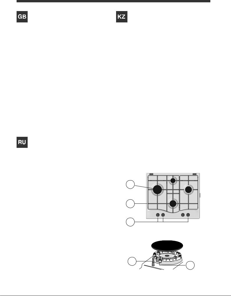
Overall view
1.Support Grid for COOKWARE
2.GAS BURNERS
3.Control Knobs for GAS BURNERS
4.Ignition for GAS BURNERS
5.SAFETY DEVICES
•GAS BURNERS differ in size and power. Use the diameter of the cookware to choose the most appropriate burner to cook with.
•Control Knobs for GAS BURNERS adjust the size of the flame.
•GAS BURNER IGNITION enables a specific burner to be lit automatically.
•SAFETY DEVICE stops the gas flow if the flame is accidentally extinguished.
Құрылғы сипаттамасы
Жалпы шолу
1ЫДЫСТАРҒА арналған тіреуіш тор
2ГАЗ ОТТЫҚТАРЫ
3ГАЗ ОТТЫҚТАРЫ басқару тұтқалары
4ГАЗ ОТТЫҚТАРЫНЫҢ тұтату құралы
5ҚАУІПСІЗДІК ҚҰРЫЛҒЫЛАРЫ
•ГАЗОТТЫҚТАРЫөлшеміменқуатынақарайәртүрлі болады. Тамақ пісіру үшін тиісті оттықты ыдыстың диаметріне қарай таңдаңыз.
•ГАЗ ОТТЫҚТАРЫ басқару тұтқалары жалынның өлшемін реттейді.
•ГАЗ ОТТЫҒЫНЫҢ ТҰТАТУ ҚҰРАЛЫ белгілі бір оттықтыавтоматтытүрдежандыруғамүмкіндікбереді.
•ҚАУІПСІЗДІК ҚҰРЫЛҒЫСЫ жалын байқаусыз өшірілсе, газ ағынын тоқтатады.
Описание изделия
Общии вид
1.Опорные решетки для КАСТРЮЛЬ И СКОВОРОД
2.ГАЗОВЫЕ КОНФОРКИ
3.Регуляторы ГАЗОВЫХ КОНФОРОК
4.Свеча зажигания ГАЗОВЫХ КОНФОРОК
5.ЗАЩИТНОЕ УСТРОЙСТВО
•ГАЗОВЫЕ КОНФОРКИ имеют разную мощность и размер. Выберите конфорку, наиболее соответствующую диаметру используемой посуды.
•Регуляторы ГАЗОВЫХ КОНФОРОК служат для регуляции пламени.
•Свеча ЗАЖИГАНИЯ ГАЗОВЫХ КОНФОРОК для автоматического зажигания нужной конфорки.
•УСТРОЙСТВО БЕЗОПАСНОСТИ при случайном гашении пламени перекрывает подачу газа.
2
1
3
5 |
4 |
|
5
GB Installation
!Before operating your new appliance please read this instruction booklet carefully. It contains important information for safe use, installation and care of the appliance.
!Please keep these operating instructions for future reference. Pass them on to possible new owners of the appliance.
Positioning
!Keep packaging material out of the reach of children. It can become a choking or suffocation hazard (see Precautions and tips).
!Theappliancemustbeinstalledbyaqualifiedprofessional according to the instructions provided. Incorrect installation may cause harm to people and animals or may damage property.
!This unit may be installed and used only in permanently ventilated rooms in accordance with current national regulations. The following requirements must be observed:
•The room must be equipped with an air extraction system that expels any combustion fumes. This may consist of a hood or an electric fan that automatically starts each time the appliance is switched on.
|
|
|
|
|
|
|
|
|
|
|
|
|
|
|
|
|
|
|
|
|
|
|
|
|
|
|
|
|
|
|
|
|
|
|
|
|
|
|
|
|
|
|
|
|
|
|
|
|
|
|
|
|
|
|
|
|
|
|
|
|
|
|
|
|
|
|
|
|
|
|
|
|
|
|
|
|
|
|
|
|
|
|
|
|
|
|
|
|
|
|
|
|
|
|
|
|
|
|
|
|
|
|
|
|
|
|
|
|
|
|
|
|
|
|
|
|
|
|
|
|
|
|
|
|
|
|
|
|
|
|
|
In a chimney stack or branched flue. |
Directly to |
|
|
|
|
|
|||||||||||||||
(exclusively for cooking appliances) |
the Outside |
|
|
|
|
|
|||||||||||||||
|
|
|
|
|
|
|
|
|
|
|
|
|
|
|
|
|
|
|
|
|
|
•The room must also allow proper air circulation, as air is needed for combustion to occur normally.The flow of air must not be less than 2 m3/h per kW of installed power.
A |
Examples of ventilation holes for comburant air.
Adjacent |
Room to be |
Room |
Vented |
Enlarging the ventilation slot |
|
between window and floor. |
|
The air circulation system may take air directly from the outside by means of a pipe with an inner cross section of at least 100 cm2; the opening must not be vulnerable to any type of blockages.
The system can also provide the air needed for combustion indirectly, i.e. from adjacent rooms fitted with air circulation tubes as described above. However, these rooms must not be communal rooms, bedrooms or rooms that may present a fire hazard.
•Liquid petroleum gas sinks to the floor as it is heavier than air. Therefore, rooms containing LPG cylinders must also be equipped with vents to allow gas to escape in
the event of a leak. As a result LPG cylinders, whether partially or completely full, must not be installed or stored in rooms or storage areas that are below ground level (cellars, etc.). It is advisable to keep only the cylinder being used in the room, positioned so that it is not subject toheatproducedbyexternalsources(ovens,fireplaces, stoves, etc. ) which could raise the temperature of the cylinder above 50°C.
Fitting the appliance
The following precautions must be taken when installing the hob:
•Kitchen cabinets adjacent to the appliance and taller than the top of the hob must be at least 600 mm from the edge of the hob.
•Hoods must be installed according to their relative installation instruction manuals and at a minimum distance of 650 mm from the hob (see figure).
•Place the wall cabinets adjacent to the hood at a minimum height of 420 mm from the hob (see figure).
|
600mm min. |
650mmmin. |
420mmmin. |
If the hob is installed beneath a wall cabinet, the latter must be situated at a minimum of 700 mm above the hob.
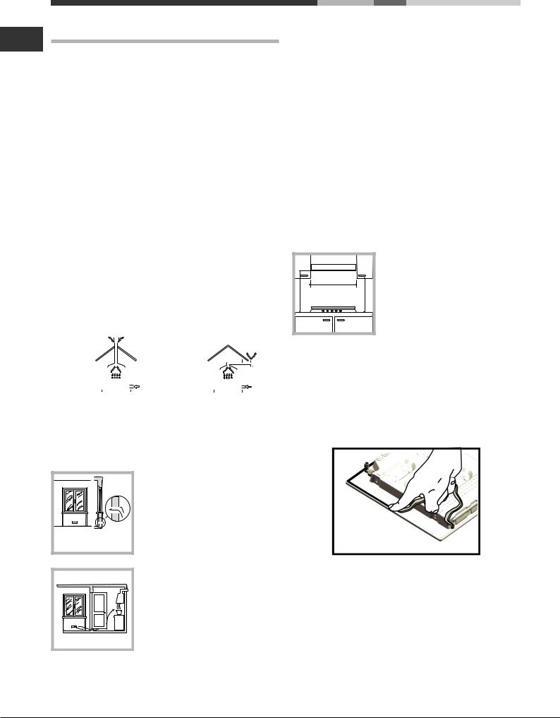
Before the installation remove the grids and burners from the hob and turn it upside down, making sure you don’t damage the thermocouples and spark plugs.
Apply the seals that come with the appliance along the outer edges of the hob to prevent any passage of air, humidity and water (see Figure).
For proper application make sure the surfaces to be sealed are clean, dry and free of any grease/oil.
•The installation cavity should have the dimensions indicated in the figure.
Fastening hooks are provided, allowing you to fasten the hob to tops that are between 20 and 40 mm thick. To ensure the hob is securely fastened to the top, we recommend you use all the hooks provided.
6

|
|
|
555 mm |
|
|
|
|
|
|
|
|
55 |
mm |
|
|
mm |
|
475 |
|||||
|
|||||
|
|
|
|||
|
|
|
|
|
|
Hook fastening diagram
Hooking position |
Hooking position |
for top H=20mm |
for top H=30mm |
|
Front |
Hooking position |
Back |
for top H=40mm |
|
! Use the hooks contained in the “accessory pack”.
•Where the hob is not installed over a built-in oven, a wooden panel must be installed as insulation. This must be placed at a minimum distance of 20 mm from the lower part of the hob.
Ventilation
To ensure adequate ventilation, the back panel of the cabinet must be removed. It is advisable to install the oven so that it rests on two strips of wood, or on a completely flat surface with an opening of at least 45 x 560 mm (see diagrams).
. |
45 |
mm. |
mm |
|
|
560 |
|
|
Where a hob is installed above an oven without a forced ventilation cooling system, adequate ventilation must be provided inside the cabinet by means of air holes through which air can pass (see figure).
GB
Electrical connection
Hobs equipped with a three-pole power supply cable are designed to operate with alternating current at the voltage and frequency indicated on the data plate (this is located on the lower part of the appliance). The earth wire in the cable has a green and yellow cover. If the appliance is to be installed above a built-in electric oven, the electrical connection of the hob and the oven must be carried out separately, both for electrical safety purposes and to make extracting the oven easier.
Connecting the supply cable to the mains
Install a standardised plug corresponding to the load indicated on the data plate.
The appliance must be directly connected to the mains using an omnipolar circuit-breaker with a minimum contact opening of 3 mm installed between the appliance and the mains. The circuit-breaker must be suitable for the charge indicated and must comply with current electrical regulations (the earthing wire must not be interrupted by the circuitbreaker). The supply cable must not come into contact with surfaces with temperatures higher than 50°C.
!The installer must ensure that the correct electrical connection has been made and that it is compliant with safety regulations.
Before connecting to the power supply, make sure that:
• The appliance is earthed and the plug is compliant with the law.
• The socket can withstand the maximum power of the appliance, which is indicated on the data plate.
• The voltage is in the range between the values indicated on the data plate.
• The socket is compatible with the plug of the appliance. If the socket is incompatible with the plug, ask an authorised technician to replace it. Do not use extension cords or multiple sockets.
!Once the appliance has been installed, the power supply cable and the electrical socket must be easily accessible.
!The cable must not be bent or compressed.
!The cable must be checked regularly and replaced by authorised technicians only (see Assistance).
!The manufacturer declines any liability should these safety measures not be observed.
Gas connection
The appliance should be connected to the main gas supply or to a gas cylinder in compliance with current national regulations. Before carrying out the connection, make sure the cooker is compatible with the gas supply you wish to
7
use. If this is not the case, follow the instructions indicated GB in the paragraph “Adapting to different types of gas.”
When using liquid gas from a cylinder, install a pressure regulator which complies with current national regulations.
! Check that the pressure of the gas supply is consistent with the valuesindicatedinTable1(“Burnerandnozzlespecifications”).
This will ensure the safe operation and longevity of your appliance while maintaining efficient energy consumption.
Connection with a rigid pipe (copper or steel)
! Connection to the gas system must be carried out in such a way as not to place any strain of any kind on the appliance.
ThereisanadjustableL-shapedpipefittingontheappliance supply ramp and this is fitted with a seal in order to prevent leaks. The seal must always be replaced after rotating the pipe fitting (seal provided with appliance). The gas supply pipefittingisathreaded1/2gascylindricalmaleattachment.
Connecting a flexible jointless stainless steel pipe to a threaded attachment
The gas supply pipe fitting is a threaded 1/2 gas cylindrical male attachment.
These pipes must be installed so that they are never longer than 2000 mm when fully extended. Once connection has been carried out, make sure that the flexible metal pipe does not touch any moving parts and is not compressed.
! Only use pipes and seals that comply with current national regulations.
Checking the tightness of the connection
! When the installation process is complete, check the pipe fittings for leaks using a soapy solution. Never use a flame.
Adapting to different types of gas
To adapt the hob to a different type of gas other than default type (indicated on the rating plate at the base of the hob or on the packaging), the burner nozzles should be replaced as follows:
1.Remove the hob grids and slide the burners off their seats.
2.Unscrew the nozzles using a 7 mm socket spanner, and replace them with nozzles for the new type of gas (see table 1 “Burner and nozzle characteristics”).
3.Reassemble the parts following the above procedure in the reverse order.
4.Once this procedure is finished, replace the old rating sticker with one indicating the new type of gas used. Sticker are available from any of our Service Centres.
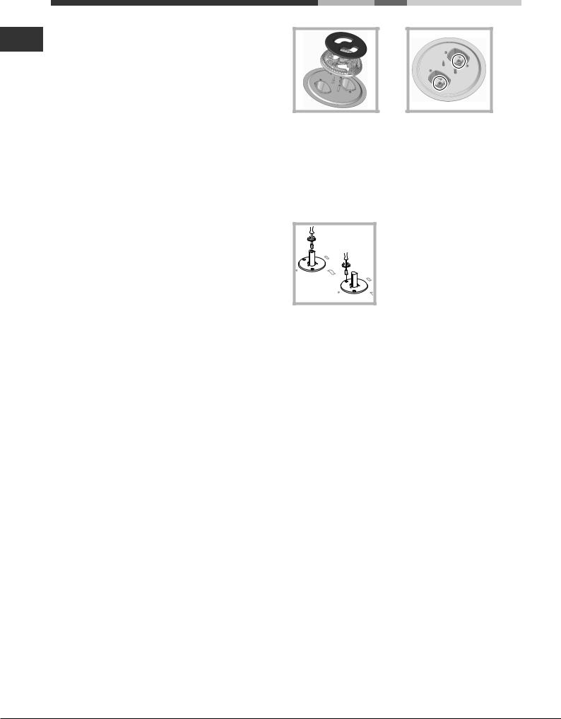
Replacing the Triple ring burner nozzles
1.Remove the pan supports and lift the burners out of their housing. The burner consists of two separate parts (see pictures).
2.Unscrew the nozzles using a 7 mm socket spanner. Replace the nozzles with models that are configured for use with the new type of gas (see Table 1). The two nozzles have the same hole diameter.
3.Replace all the components by completing the above operations in reverse order.
•Adjusting the burners’ primary air Does not require adjusting.
•Setting the burners to minimum
1.Turn the tap to the low flame position;
2.Remove the knob and adjust the adjustment screw, which is positioned in or next to the tap pin, until the flame is small but steady.
3.Having adjusted the flame to the required low setting, while the burner is alight, quickly change the position of the knob from minimum to maximum and vice versa several times, checking that the flame does not go out.
4.Some appliances have a safety device (thermocouple) fitted. If the device fails to work when the burners are set to the low flame setting, increase this low flame setting using the adjusting screw.
5.Once the adjustment has been made, replace the seals on the by-passes using sealing wax or a similar substance.
!If the appliance is connected to liquid gas, the regulation screw must be fastened as tightly as possible.
!Once this procedure is finished, replace the old rating sticker with one indicating the new type of gas used. Stickers are available from any of our Service Centres.
!Should the gas pressure used be different (or vary slightly) from the recommended pressure, a suitable pressure regulator must be fitted to the inlet pipe (in order to comply with current national regulations).
8
|
|
|
|
|
|
DATA PLATE |
|
|
|
|
|
|
|
|
GB |
||
Electrical |
|
|
|
|
|
see data plate |
|||||
connections |
|||||
This appliance conforms to the following
European Economic Community directives:
-2006/95/EEC dated 12/12/06 (Low Voltage) and subsequent amendments
-2004/108/EEC dated 15/12/04 (Electromagnetic Compatibility) and
subsequent amendments
- 93/68/EEC dated 22/07/93 and subsequent amendments.
- 2009/142/EEC dated 30/11/09 (Gas) and subsequent amendments.
- 2012/19/EC and subsequent amendments.
9
 Loading...