

Page 1
Comfort Compact Controller ZG 252N
OPERATION AND PUTTING INTO SERVICE
142 376
4,5 3,5 3,0 2,5
ZG252 N
auto1
°C
100
80
60
40
0
+10
B
-8
C
-8 1,60
P1 ACB
2
1,8
1,6
1,4
A
1,2
1
0,8
0,6
0,4
-20°C+5 -10 -15-50
8311.7151
5
P1
L1 L2 P1
S
CBA
C
20
B
A
CB5025.7
Page 2
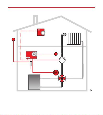
System diagram
AF
TW
//
ZG252N
////
ZG Control Unit
VF Flow sensor
AF Outdoor sensor
TW Temperature selector (Option)
VF
//
////
VM
////
P
ZR
ZR Heating mixing valve
VM Servomotor
P Heating circuit pump
CBZG037.cdr
Page 3

Operating of the Control
(see figure on the left)
The outdoor sensor (AF) measures the outside temperature.
It transmits its measured value to the control unit, which determi
nes the necessary hot water temperature (flow temperature).
Theflow sensor (VF) measures the water temperature in the hea
ting flow. Itsenses also the changes that are caused by the oscilla
tions inthe boiler orheating return temperature.If the flowtempe
rature differs from the target value, the control unit adjusts the
mixing valve (ZR) with the servomotor (VM) so that the right
heat input can be reached.
Themixing valve determines the flow temperature by mixing the
boiler’s hot water with the colder return water.
Theheating circuit pump (P) provides for the heating circuit of
the hot water. It is switched off by the control unit, if the heating
circuit is necessary.
Thetemperature selector(TW) is used as a remotecontrol, e.g. if
the controlunit is mountedin the cellar.The room temperaturecan
be changed with selector knob P2 . The party switch S1 makes
it possibleto increase thenight-time decrease intemperature. (The
temperature selector is not needed necessarily and is not supplied
with the compact control unit.)
-
-
-
-
Page 4

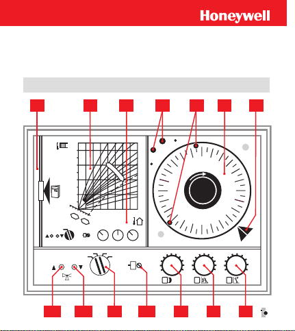
Operating and Display Components
Pos. Function Basic Setting
A
Heating curve diagram
B
Parallel shift
C Reduced mode -8
P1 Sensitivity 10
S Operating mode selector auto 1
L1 “Hotter” LED (red)
L2 “Colder” LED (green)
1 Instructions compartment
2 Heating curve diagram
3 Basic settings
4 Reserve Trip Pins
5 Inserted trip pins
6 Timer (optional)
7 Pointer for the current time
Settings on the temperature selector
P2 Selector knob 0
S1 Party switch auto
-1.6
0
Page 5

Operating mode selector
manu The control unit is deactivated (the timer runs).
The mixingvalve can be set manually(by hand). The heting circuit
pump is switched on.
auto 1 Recommended setting forimproved energy saving: Auto
matic change between day and reduced mode according to the ti
mer, with night switch-off. During night mode, the mixing valve
remains closed completely at outside temperatures of more than
+2 °C andthe heating circuit pump isswitched off. At outside tem
peratures below +2 °C the pump runs for frost protection and the
controller works withthe nightdecreaseset on the setting knob C.
auto 2 Recommended settingfor automatic change between day
and reduced mode according to the timer.
The decrease set on the setting knob C is active.
-
-
-
2 The mixing valve is kept closed constantly and the heating cir
cuit pump is switched off. The timer runs.
Energy saving tip: A particularly great energy
savings can be made if the switch position auto 1
is selected. In this switch position it may happen
that the heating lasts longer.
-
Page 6
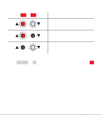
LED’s
L1 L2
Both LED’s light up:
“neutral” – Mixing valve stops
Only the red LED lights up:
“hotter” – Mixing valve opens
Only the green LED lights up:
“colder” – Mixing valve closes
In the manu or 2 settings of the operating mode selector S
there is no LED display.
Page 7

Putting into service
Set the timer 6 at the current time.
n
Set the operating mode selector S on auto 1 or auto 2 .
n
The switchis in position 2 when itleaves the factory.The pump is
hence switched off and is protected against the dry-running of the
empty heating system.
Warning: In switch position 2 the 230V line voltage
is between terminals 8 and 11 of the control unit!
(The servo motor closes).
The remainingfactory settings are printed under 3 on the control
ler.
-
Timer for reduced mode 6
With theaid of the timer,the temperature ofthe rooms can beauto
matically reduced when they are not used to save on the operating
costs.
The timer has a built-in power reserve of approx. 60 hours thanks
to a rechargeable battery.
-
Page 8

Changing the program
Factory settings: red pin 6:00, blue pin 22:00.
Pull out the trip pin and insert it again at the desired switch-
n
on time. Push in the trip pins until they reach the stop.
Owing to the different lengths, the trip pins must always be inser
ted in a red/blue alternate order. Thered trip pin switches on day
mode, while the blue pin activates reduced mode.
In order tomake surethat the rooms are heated well inthe morning,
the heating system’sday mode should be activated between ahalf
an hour and an hour before using the rooms.
Energy saving tip: Reduced mode can be activated
up to an hour before the room is left. The storage
capacity of the heating system and building is
enough to keep the rooms warm for some time.
Timer with day program
The day program is repeated every 24
hours. Ifa (second) decrease intempera
ture is desired in the course ofthe dayto
save energy, the program needs to be
extended. Takethe extra trippins 4 and
insert them at the desired time.
-
-
CB5044.7.cdr
Page 9

Example:
Desired time program
Normal temperature: 6:00 h to 8:00 h and 16:00 h to 22:00 h
Night decrease: 22:00 h to 6:00 h
day decrease: 8:00 h to 16:00 h
Position of the trip pins
red pin 6:00 h – Start day mode (normal temperature)
blue pin 8 :00 h – Start daily decrease
red pin 16:00 h – Start day mode (normal temperature)
blue pin 22:00 h – Start night decrease
Timer with week program
The timer has a changeable dial.
With the week program, dialling a different heating program for
each weekday is possible.
The dial isprepared exfactory for the day program and,if required,
it can bechanged toweekprogram (see installation instructions).
Setting the right time
To setthe time, the timedial is to beplaced on the trippins andtur
ned clockwise until the indication on the setting marker 7 mat
ches with the current time.
-
-
Page 10

Optimization of the Settings
Basic settings fora hot water heating systemworking at water tem
peratures between 20 °C and 90 °C:
A è 1,6 B è 0 C è -8
I è Day mode curve / II è Reduced mode curve
During the optimization, the radiator valves are completely
n
open. (Set the radiator thermostat valves at the maximum value)
Close all windows and doors.
n
Proceed gradually by making only small changes!
Wait for the outcome of the change after each
setting (approx. 1 h).
Depending on the type of system – radiator/convector heating
(up to 90 °C), low temperature heating, air heating, – and depen
ding on the layout of the heating surfaces, various flow or supply
temperatures are needed to reach the right room temperature and
hence also different settings on the setting knobs.
Heating curve selection (Setting knob A )
The adaptation of the controller to the heating system and to the
building characteristics of the house is carried out by setting the
heating curve with the setting knob A . The heating curves show
the relation between the outside temperature and the necessary
flow temperature. Each buildingmust be assigned an optimalhea
ting curve.
-
-
-
Page 11

The lowerthe maximum flowtemperature at basisof the calculati
on ofthe heating system and themore numerous the heating surfa
ces are, the morelevel the heating curve canbe selectedand hence
the smaller thenumeric valuetobe set on the setting knob A is.
Basic setting: A è 1.6 (curve I in the diagram).
Displacement (room temperature change)
With settingknob B , theheating curve seton the settingknob A
can be moved in parallel along the room temperature axis (repre
sented obliquely in the diagram). This displacement leads to a
change in the room temperature.
Basic setting: B è 0
The scale division on setting knob B corresponds approximately
to the change in the room temperature in K (°C).
+ means “increase the room temperature”
– means “lower the room temperature”
B è 0 corresponds approx. to a room temperature of 20 °C
B è +2 corresponds approx. to a room temperature of 22 °C
Pay attention also to “Remote Control TF 22”.
-
-
-
Page 12

Night decrease setting knob C
On setting knob C , the size ofthe nightdecrease to be triggered by
the timer is to be set.The settingon setting knob C leads to apar
allel shift of theheating curve downward along the room tempera
ture axis (dotted curve II ). The flow temperature and the room
temperature arehence reduced. Thescale division onsetting knob
C corresponds approximately to a °K (°C) room temperature de
crease. 0 means no decrease.
-
-
-
Example:
C è -8 means that the room temperatureat night can drop by ap
prox. 8 K below the set day temperature and hence e.g. to 12 °C
(20 °C - 8 °C = 12 °C).
The recommendedsetting C è -8 makes itpossible to savequite
a lot of energy with a large nighttime decrease. In some buildings
the rooms may become too cold.
In these cases it is recommended to set a night decrease value of
only about 5 °C ( C è -5 ) or to switch on day mode earlier.
-
Page 13

Remote control TF 22 (optional)
Setting the Room Temperature
On setting knob P2 , the setting of the room temperature can be
fine-tuned.
The normal setting is the room temperature set on the control unit
(setting knob B ) (mainly 20 °C to 22 °C,the roomtemperature is
not measured on the temperatureselector). The scale on the selec
tor is divided from-7 to +7 and matchesmore or less to thechange
in degrees.
+ è Increasing the Room Temperature
– è Lowering the Room Temperature
The functioning of the selector knob P2 corresponds to the
functioning of the setting knob B on the control unit and gives a
parallel displacement of the heating curve along the oblique room
temperature axis indicated in the diagram.
S1
P2
-
Page 14

The valueson the selector knob P2 and the settingknob B are ad
ded on the control unit:
Examples
Selector knob P2 −1 0 +1 +2 −1 0 +1 +2
Room temperature
[°C]
If no temperature selector is available, the desired room tempera
ture can be set only on the setting knob B of the control unit.
B è 0 B è +1
19 20 21 22 20 21 22 23
-
-
Page 15

Party switch S1
The temperature selector’sparty switchhasthe following settings:
auto automatic change to day mode or
to reduced mode according to the timer
manual day mode, timer not active
manual night mode, timer not active
(the “night” duration mode is possible only if the
hours are set.)
If, for example, the heating is to stay open longer,
the Partyswitch is to be set on manual day mode.
Do not forget to switch back if the automatic mode is
to be activated again later on.
Page 16

Remote control TFU 22 (optional)
When using remote control TFU 22 (instead of TF 22), a time can
be pre-set (e. g. 10 days) during which the heating system is to
work in economymode (theanti-freezeprotection is hence active.)
At the expiry of the selected time, the TFU 22 resets the control
unit backto automatic mode. There isno need to remember toreset
the switch. Economy mode (night) is possible only if the time is
set.
P2
Page 17

Adjustments to the Room Temperature
If in case of varying outside temperatures the setting of the TF
needs tobe changed frequentlyto obtain asteady room temperatu
re, modify the control unit’s setting as follows:
1. The room temperature is too low:
n
In the rooms it is...
a) too cold at any outside temperature:
A è 1.6
B è +1 … +2
b) too cold only with mild outside temperatures:
A è 1.2 … 1.4
B è +1 … +2
c) too cold only at very cold temperatures:
A è 1.8 … 1.9
B è 0
2. The room temperature is too high:
n
In the rooms there is...
a) too hot at any outside temperature:
A è 1,6
B è −1…-2
b) too hot only with mild outside temperatures:
A è 1.8
B è -1…- 2
c) too hot only at very cold temperatures:
A è 1.2 ... 1.4
B è 0
Tendency of
correction
A no corr.
B increase
A decrease
B increase
A increase
B no corr.
A no corr.
B decrease
A increase
B decrease
A decrease
B no corr.
-
Page 18

Pump
Demand-responsive mode
The control unit can switch on the heating circuit pump on a de
mand- responsivebasis. It isswitched on onlyby the controlunit if
a heat input is needed, i. e. if the target value of the heating flow
temperature is higher that the target value of the room temperatur
(pump logic).
In case of the frequently usual setting of the control unit
S è auto 2 / B è 0 / C è -8
the heating circuit pump is switched off:
in day mode at outside temperatures over 20 °C
n
in reduced mode at outside temperatures below 12 °C
n
In position auto 1 of the operating mode selector, the switch-off
times of the pump are longer.
Blocking protection
The timer is equipped at the factory so that the heating circuit
pump runs for about a minute every day, even if no heating is
necessary (Requirement: the operating mode selector S is on
auto 1 or auto 2 ). Theheating circuit pump can hence avoidre
maining stuck and blocked also during long periods of idleness
(summer).
-
-
Page 19

Troubleshooting Checklist
Are the heater valves (thermostat valves) turned too far?
n
Is the boiler at the required temperature?
n
è Read the boiler thermometer.
Is the burner ready?
n
Is the burner failure lamp on?
è If necessary, press the reset button.
Was the temperature selector set by mistake?
n
Check the setting of the selector knob P2 or of the Party
switch S1 .
Check the setting on the control unit Setting knobs
n
AB Cand operating mode selector S
Is the timer running? Is the displayed time correct?
n
è Check the time and switch-on point.
If the problem still has not been solved after checkingthe settings,
position the setting knob B on +7
The servomotor should now open the mixing valve and the red
LED L2 should light up. If this is not the case, the control system
has failed. Contact your heating technician.
Page 20

Manual mode
CB5043.7.cdr
Page 21

Manual mode (left-hand fig.)
In case of the breakdown of the heating mode regulation you can
proceed temporarily as follows:
1. Set the operating mode selector S on manu .
n
2. Open the mixing valve by hand until the desired flow and
n
room temperatures are reached.
– The coupling incorporated in the mixing valve drive unit
provides for the release of the connection between the
motor and the mixing valve.
– Press firmly on the unlock key on the cover of the drive
unit and keep the key pressed (firmly!).
– Use the setting lever to set the mixing valve to the desi
red position.
After eliminating the problem, the mixing valve is
set again to the right position by the control unit in
automatic mode.
-
Page 22

Heating curves
°C
100
80
60
Flow temperature[°C]
40
+10
0
B
Room temperature
change[°C]
4.5 3.5 3.0 2.5
+10
-8
External temperature [°C]
C
CB50427E
2
1.8
1.6
I
A
1.4
1.2
II
1
0.8
0.6
0.4
-20°C+5 -10 -15-50
Page 23

Instructions for the technician (only!)
Removing the Timer
(see also the installation instructions)
1. Pull out the instructions case.
n
2. Hold the timer by the two white stems and turn to the left
n
until the connector is released.
3. Remove the timer.
n
(To install the timer, proceed in the opposite order.)
Pump activation
If the temporary forceddrive ofthe heating circuit pump isnot de
sired while the heating system is idle, one of the jumpers on the
back of the timer is to be removed.
1. Remove the timer.
n
2. Remove jumper 55.
n
3. Mount the timer again.
n
Regulation Stability (Sensitivity)
The stability of the regulation canbe modified with the setting po
tentiometer P1 .
For the regulation technician:
By means of P1 , set the proportional range of the PD control
unit. Recommended basic setting: P1 è 10.
In case of unstable regulation, set higher values.
-
-
Page 24

Reference
Installation instructions
Compact Control Units ZG 215N / 215 VN / 252 N
GE 1H-0181 GE51
Operating Instructions
ZG 252N: EN-2H0215 GE51
ZG 215N: EN-2H0216 GE51
ZG 215VN: EN-2H0217 GE51
“Informationsschrift”(Planning broschure in German)
L3 – Komfort-Compact Regler
GE-0H 0327 GE51
Centra Regelungstechnik http://www.honeywell.de/hga
Honeywell AG
Böblinger Straße 17
D 71101 Schönaich
Telefon +49 (70 31) 637-01
Telefax +49 (70 31) 637-493
Technical data may be changed without prior notice.
EN 2H-0215 GE51 R1001 7157 561
 Loading...