

Page 1
9.Zubehör
D
GB
9.Accessories
F
9.Accessoires
E
9.Accessori
9. Дополнительные
R
принадлежности
Differenzdruckschalter
D
GB
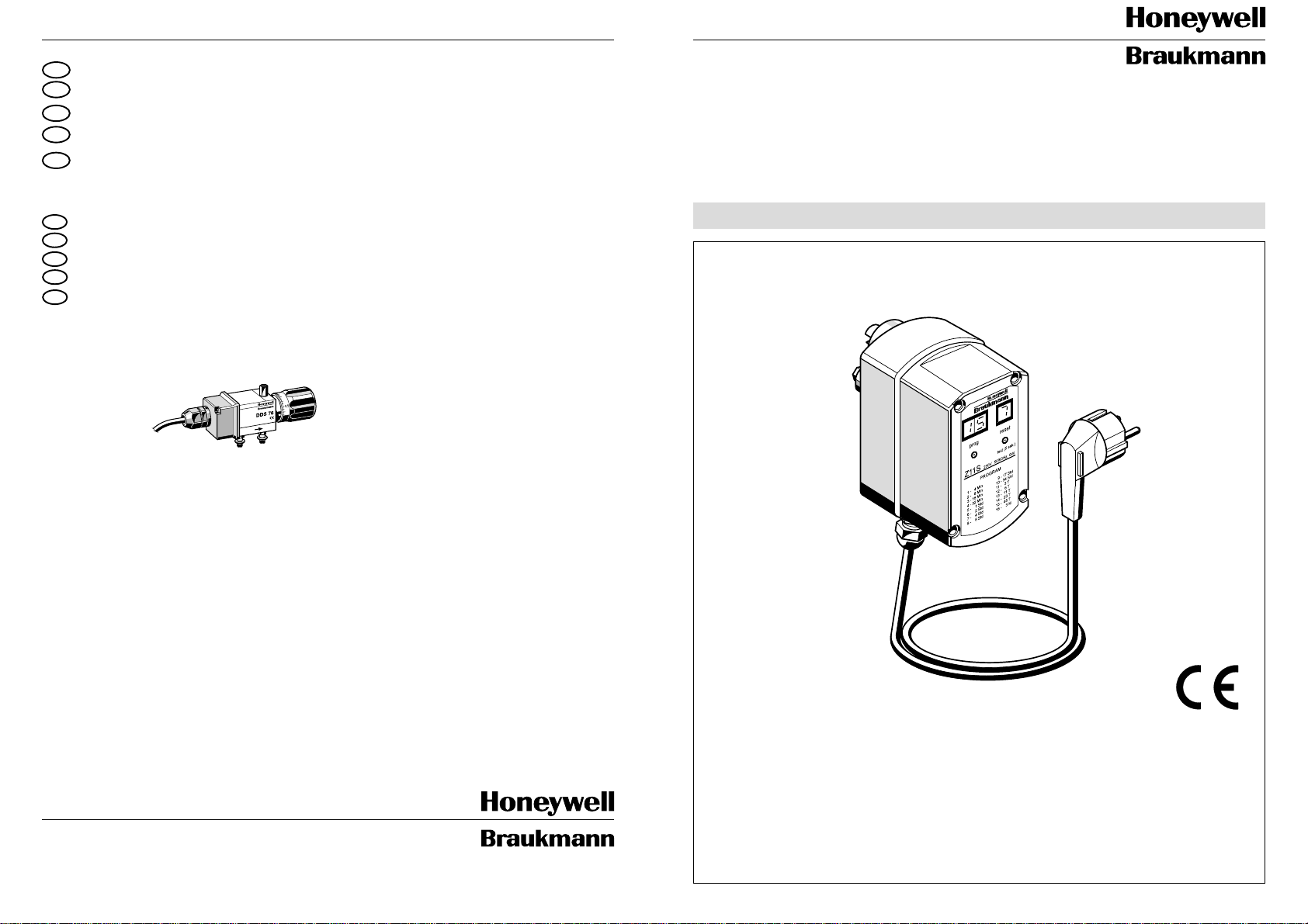
Differential pressure switch
Contacteur à pression différentielle
F
Contattore di pressione differenziale
I
Реле перепада давления
R
Z 11 S
Einbau-Anleitung . Installation Instruction . Instructions de montage
Istruzioni per il montaggio
.
Привод обратной промывки
DDS 76DDS 76-1 F 76-1" + 11/4"
DDS 76-11/2 F 76-11/2" + 2"
1
/2 F 76-1/2" + 3/4
F 76-F, DN 65-100
Rückspülautomatik
Reverse Rinsing Actuator
Braukmann Armaturen
Honeywell AG
Hardhofweg . D-74821 Mosbach
04/99
Automate de rinçage à contre-courant
Automa di lavaggio in controcorrente
Инструкции по монтажу
EB-Z 11 S 2402500
Page 2
A
Inhaltsübersicht Seite
D
1. Einbau 2
2. Montage 2
3. Rückspülwasserabführung 2
4. Batterien/Sicherung einsetzen 2
5. Einstellen des Rückspülintervalls 2
6. Zusatzfunktionen 3
7. Sicherheitshinweise 3
8. Technische Daten 3
9. Zubehör12
2.1 2.2
1
2
2.3
Index Page
GB
1. Installation 4
2. Assembly 4
3. Reverse Rinsing Water Drainage 4
4. Fitting Batteries and Fuses 4
5. Setting of the reverse Rinsing Interval 4
6. Additionale Functions 5
7. Safety Guidelines 5
8. Technical Data 5
9. Accessories 12
Index Page
F
1. Installation 6
2. Montage 6
3. Evacuation de l’eau de rinçage à contre-courant 6
4. Installation des piles/fusibles 6
5. Setting of the reverse Rinsing Interval 6
6. Règlage de la frèpuece de rincages à contre-courant 7
7. Fonctions supplèment aires 7
8. Specifications techniques 7
9. Accessoires 12
Indice Pagina
I
1. Installazioni 8
2. Montaggio 8
3. Scarico dell`asqua di cicolazione inversa 8
4. Installazione delle pile 8
5. Regulazione degli intervalli di lavaggio in contro-corrente 8
6. Funzioni suppletive 9
7. Indicazioni di siccurezza 9
8. Dati tecnici 9
9. Accessori 12
4.1
3.2
300
C
4.4
Sicherung 800 mA / F
Fuse 800 mA / F
Fusible 800 mA / F
Fusibile 800 mA / F
Предохранитель на 800 мА/Ф]
4.3
3.1
B
5
Serienmäßig ist ein Rückspülintervall von 45 T agen eingestellt.
3
2
1
5
A reverse rinsing interval of 45 days is set during manufacture.
Le réglage standard de la fréquence est de 45 jours.
4
La regolazione standard in fabbrica dell’intervallo è di 45 giorni.
При выпуске с завода-изготовителя периодичность обратной промывки
отрегулирована на 45 дней]
Оглавление
R
1. Монтаж 10
2. Сборка 10
3. Отвод воды обратной промывки 10
4. Установка батарей и плавких предохранителей 10
5. Задание периодичности обратной промывки 10
6. Дополнительные функции 11
7. Меры безопасности 11
8. Технические данные 11
9. Дополнительные принадлежности 12
6.1a)
b)
U=5,4 V
I= 10mA
6.2 6.3
GND
Page 3
D D
1. Einbau
Beim Einbau sind die örtlichen Vorschriften,
sowie allgemeine Richtlinien und die
Einbau-Anleitung zu beachten. Der Einbauort muß frostsicher und gut zugänglich sein.
2. Montage
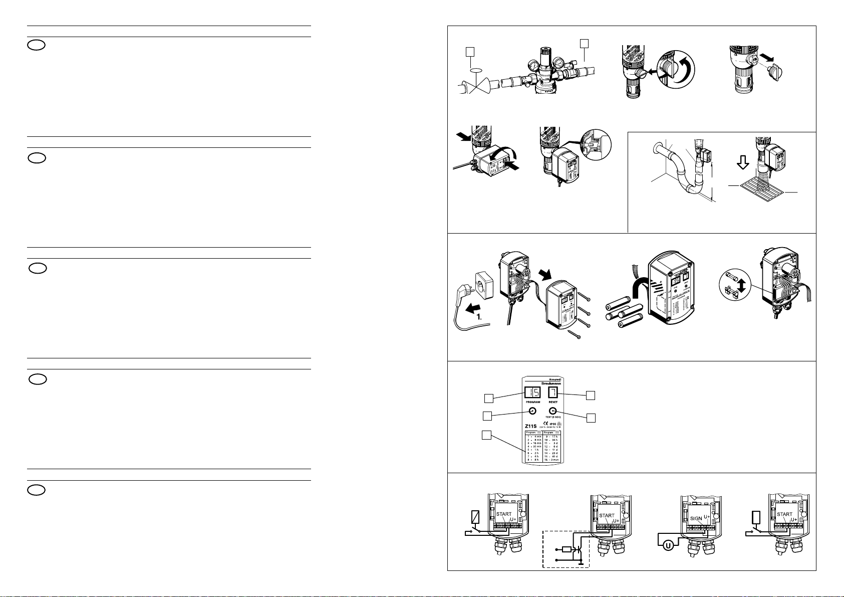
2.1 Absperrventile 1 und 2 schließen.
2.2 Kugelhahn am Filter durch Drehen
des Rückspülknopfs öffnen
● Markierungsbalken muß senkrecht
stehen.
Für geeigneten Wasserabfluß oder
Auffanggefäß sorgen.
2.3 Rückspülknopf am Filter abziehen.
2.4 Rückspülautomatik mit Bajonettverschluß anflanschen
● Z 11 S einstecken
● Gehäuse gegen Kugelventil in Richtung
Filter drücken, gleichzeitig von der
anderen Seite gegenhalten und Gehäuse um 90° drehen.
2.5 Netzstecker einstecken
Nach dem Einstecken des Netzsteckers
wird ein Rückspülvorgang ausgelöst.
3. Rückspülwasserabführung
3.1 Direkter Anschluß
Ablaufleitungen sind nach DIN 1988
auszulegen.
Leitungsquerschnitt A unbedingt
einhalten, da es sonst zum Überlaufen
der Ablaufleitung kommen kann.
Filter- Leitungs- Übergangs- Rückspül- C
Größe querschnitt stück menge mm
1
/2" + 3/4" DN 70 DN 50/70 ca. 12 3 00
1" + 11/4" DN 70 DN 50/70 ca. 15 3 00
11/2" + 2" DN 70 DN 50/70 ca. 18 300
* alle erforderlichen Rohre und Siphon (3 Bögen 90°)
** bei 4 bar Betriebsdruck und 25 s Rückspüldauer
☞ Bei Verwendung unseres Ablaufan-
3.2 Ablauf in vorhandenen Bodenabfluß
A* B in Liter**
schlußes ist der nach DIN 1988
geforderte freie Auslauf von 20 mm
integriert.
4. Batterien/Sicherung einsetzen
Die Batterien sorgen bei einem Stromausfall
während der Rückspülung für das ordnungsgemäße Schließen des Kugelhahns.
☞ Die Batterien sind nicht im Lieferum-
fang enthalten.
4.1 Netzstecker ziehen
4.2 Gehäuseschrauben lösen und Gerätedeckel abnehmen
4.3 Batterien einsetzen
(4 Mignon-Batterien 1,5 V, LR 6 AlkaliMangan)
4.4 Sicherungen bei Bedarf wechseln
4.5 Montage in umgekehrter Reihenfolge.
Bei eingelegten Batterien Netzstecker
nicht über längere Zeit aus der Steck dose ziehen.
5. Einstellen des Rückspül-
intervalls
☞Nach DIN 1988 muß spätestens alle
2 Monate eine Rückspülung durchgeführt werden. Die Rückspülintervalle
sind vom Verschmutzungsgrad des
Wassers abhängig.
Einstellen anderer Intervalle
● Gewünschtes Intervall in Tabelle 1 auf
Gehäuseaufdruck auswählen
● Programm-Taste 2 solange betätigen
bis im Display 3 das gewählte Programm
erscheint.
☞Display 5 zeigt die Anzahl der durchge-
führten Rückspülungen. Ein Rückstellen
des Zähler erfolgt durch kurzes Betätigen
der Reset-Taste 4 .
Nach einem Stromausfall wird bei Wiedereinsetzen des Netzstroms automatisch ein Rückspülvorgang ausgelöst. Das eingestellte Zeitprogramm und der Zählerstand bleiben erhalten. Durch Drücken der Reset-Taste 4 kann
der Zählerstand 5 auf 0 gesetzt werden.
Manuelles Auslösen einer Rückspülung
● Reset - Taste 4 5 Sekunden gedrückt
halten.
Serviceanzeigen
Bei gleichzeitigem Drücken der ProgrammTaste 2 und der Reset-Taste 4 (5 Sekunden gedrückt halten) wird im Display 3 die
verbleibende Zeit bis zum nächsten programmgesteuerten Rückspülen angezeigt
und im Display 5 die dazugehörige Zeiteinheit
(0= Minuten, 1= Stunden, 2= Tage).
6. Zusatzfunktionen
6.1 Fernschaltung
Die Z 11 S läßt sich fernauslösen durch
a) einen potentialfreien Umschaltkreis
(z.B.Honeywell Centra Bürkle Typ REL 2)
b) über einen Open-Collector-Ausgang
Die Mindesthaltezeit beträgt bei beiden
Fällen 1 Sekunde. Die Rückspülung erfolgt nachdem die Eingänge START und
U+ wieder getrennt wurden.
6.2 Fernüberwachung
Zur Fernüberwachung der Auf-Zu-Stellung
des Kugelventils empfehlen wir die Installation eines Gerätes der Zentralen Leittechnik 0...10 V Eingang. Der max. Strom
beträgt 10 mA. Bei anliegender Netzspannung bedeutet ein Istwert kleiner 0,5 V, daß
das Kugelventil offen ist. Bei einem Wert
zwischen 5 V und 6 V ist das Kugelventil
geschlossen.
6.3 Differenzdruckschalter
Die Rückspülfunktion läßt sich mit dem
Differenzdruckschalter DDS 76 mit potentialfreiem Mikroschalter bedarfsabhängig
auslösen. Wir empfehlen eine Einstellung
auf 1 bar Differenzdruck. Die Auslösung der
Rückspülfunktion erfolgt erst nachdem die
Eingänge START und U+ wieder getrennt
wurden, d.h. nach Abfallen des Differenzdruckes unter den eingestellten Wert.
Dadurch wird gewährleistet, daß eine
maximale Wassermenge für die Rückspülung zur Verfügung steht.
Soll die Rückspülung jedoch sofort, also
unabhängig von der Dauer des Differenzdrucksignals erfolgen, so sind stattdessen
die Eingänge U+ und SIGN anzuschließen.
Der Differenzdruckschalter DDS 76
kann gemeinsam mit Z 11 S nur beim
Feinfilter F 76 S eingesetzt werden.
7. Sicherheitshinweise
7.1 Benutzen Sie das Gerät
● in einwandfreiem Zustand
● bestimmungsgemäß
● sicherheits- und gefahrenbewußt.
7.2 Beachten Sie die Einbau-Anleitung.
7.3 Lassen Sie Störungen, welche die
Sicherheit beeinträchtigen können,
umgehend beseitigen.
7.4 Die Rückspülautomatik Z 11 S darf
ausschließlich zum Rückspülen von
Honeywell Braukmann Filtern und
Filterkombinationen eingesetzt werden.
Eine andere oder darüber hinausgehende Benutzung gilt als nicht
bestimmungsgemäß.
Alle elektrischen Anschlüsse der
Zusatzfunktionen sind von einem
Fachmann auszuführen.
Örtliche Vorschriften sind unbedingt zu
beachten.
Zum Reinigen keine lösungsmittelhaltigen Pflegemittel verwenden.
Aus Sicherheitsgründen ist eine Absicherung der Anschlußstelle erforderlich.
8. Technische Daten
Das Gerät ist serienmäßig funkentstört.
Nennspannung Ausführung A = 230 V ~
Ausführung B = 24 V ~
Frequenz 50 / 60 Hz
Leistungsaufnahme 10 W
Netzkabel 1,5 m
Batterielebensdauer ca. 3 Jahre
Sicherung 800 mA / F
Rückspüldauer bei Netzbetrieb ca. 25 s
Rückspülmenge siehe Tabelle 3.1
Umgebungsbed. 5 . . . 90 % r. F.; 0 . . . 60 °C
Schutzart IP 55 Spritzwassergeschützt
Schutzklasse 1 (DIN VDE 0700-T1 / EN
60335-1)
Abmessungen ca. Breite: 70 mm
Tiefe: 160 mm
2 3
Page 4

GB GB
1. Installation
It is necessary during installation to
observe codes of good practice, to comply
with local requirements and to follow the
installation instruc-tions. The installation
location should be protected against frost
and be easily accessible.
2. Assembly
2.1 Close isolating valves 1 and 2 .
2.2 Open the ball valve on the filter by
turning the reverse rinsing knob.
● The marker bar must be vertical.
Check availability of a suitable
drainage outlet or catchment vessel.
2.3 Pull off the reverse rinsing knob on the filter
2.4 Fit the automatic reverse rinsing
actuator with the bayonet connector
● Plug in the Z 11 S
● Push the housing in the direction of the
filter against the ball valve and at the
same time firmly restrain filter and turn
the housing through 90°.
2.5 Plug in the mains plug.
This will cause a reverse rinsing cycle
to occur.
3. Reverse Rinsing Water Drainage
3.1 Direct Connection
Connect drainage according to DIN 19886
or to national standards.
Drainage connection must have a
minimum cross section ‘A’ as indicated
in table below to prevent overflow from
the pipework.
Filter Diamete r Transition Reverse C
size pipe Connector Rinsing mm
1
/2" + 3/4" DN 70 DN 50/70 Approx. 12 300
1" + 11/4" DN 70 DN 50/70 Approx. 15 300
11/2" + 2" DN 70 DN 50/70 Approx. 18 300
* All necessary pipes and tundish (3 X 90° bends)
** At 4.0 bar operating pressure and 25 second reverse rinsing duration
A* B Quantity
(litres**)
☞When our drain connector is used, the free
20 mm discharge dimension required in
DIN 1988 is integral with the connector.
3.2 Discharge into existing floor drainage
4. Fitting Batteries and Fuses
The batteries provide a power supply to
close the ball valve in compliance with
regulations if the mains current fails during
the reverse rinsing cycle.
☞ Batteries are not supplied with the
appliance.
4.1 Pull out the electrical mains plug
4.2 Unscrew the housing screws and
remove the lid.
4.3 Insert the batteries (Four LR 6 - 1.5 V Mignon/AA size alkali-manganese)
4.4 Change fuses if necessary
4.5 Reassemble in reverse order.
Do not leave the mains unplugged for
too long when batteries are fitted.
Service Indicator Displays
If programme pushbutton 2 and reset
pushbutton 4 (for five seconds)are pushed
at the same time, the remaining time to the
next timed reverse rinsing cycle is indicated
on 3 and display 5 will indicate the
corresponding time interval between reverse
rinsing cycles (0 = minutes, 1 = hours and
2 = days)
6. Additional connection
options
6.1 Remote switching
The Z 11 S can be remotely actuated by:
a)A volt-free switching circuit (e.g.
Honeywell Centra Bürkle type REL 2)
b)Via an open-collector output.
In both cases the minimium holding
5.Setting of the Reverse
Rinsing Interval
☞DIN 1988 requires that a reverse rinsing
cycle must occur at intervals of not more
than two months. The time interval
should be set according to the level of
contamination present.
Setting of Other Intervals
● Select required interval from the table 1
on the housing cover
● Press pushbutton 2 until the required
programme appears on display 3
☞ Display 5 indicates the number of
completed reverse rinsing cycles. This
number can be reset by briefly
pressing pushbutton 4 .
After electrical power has failed, when it is
restored a reverse rinsing cycle will automatically occur. The set timed programme and
counter reading are retained. Counter 5 can
be reset to 0 by pressing reset button 4 .
Manual Actuation of the Reverse Rinsing
Reset - press pushbutton 4 for five seconds
period is one second. Reverse rinsing
occurs when the inputs “Start” and “U+”
have been separated.
6.2 Remote monitoring
For remote monitoring of the open/closed
position of the ball valve the installation of a
building management system with 0 to 10V
input is recommended. The maximum current
is 10 mA. With a current of 0.5 V the ball valve
is open and with a value between 5V and 6 V
the ball valve is closed.
6.3 Differential pressure switch
The reverse rinsing function can be actuated
according to demand using the DDS 76 differential pressure switch with voltage free
switching. It is recommended that the differential pressure be set to 1.0 bar. Operation
occurs when the inputs “Start” and “U+” have
been separated, that is, after the differential
pressure has fallen below the set value.
Through this it is guaranteed that a maximum
quantity of water is available for reverse
rinsing. If reverse rinsing starts immediately
irrespective of the duration of the differential
pressure signal, then the inputs should be
connected instead to “U+” and “SIGN” .
The DDS 76 differential pressure switch
can only be used where F 76 S fine
filters are also installed.
4 5
7. Safety Guidelines
7.1 Use appliance only:
● In good condition
● According to regulations
● With due regard to safety
7.2 Follow installation instructions
7.3 Immediately rectify any malfunctions
which may influence safety.
7.4 The Z 11 S automatic reverse rinsing
actuator is exclusively for use in
reverse rinsing applications with
Honeywell Braukmann filters and filter
combinations. Any variation from this
or other use will not comply with
requirements.
All electrical work must be carried out
by authorised specialists and comply
with local regulations.
Materials containing solvents must not
be used for cleaning.
For safety reasons it is required that a
fuse be fitted to protect the electrical
junction box.
8. Technical Data
The appliance is fitted with electrical
suppression during manufacture.
Nomin a l voltag e Version A = 230 V ~
Version B = 24 V ~
Frequency 50 / 60 Hz
Electrical consumption 10 W
Supply cable 1,5 m
Battery life Approximately 3 years
Fuse 800 mA / F
Reverse rinsing Approximately 25 s with mains
duration electricity
Reverse rinsing
quantity See table 3.1
Ambient conditions 5 . . . 90 % humidity; 0 . . . 6 0 °C
Type of protection IP 55 water vapour protected
Protection class 1 (DIN VDE 0700-T1 / EN 60335-1)
Approx. dimensions Width: 70 mm
Depth: 160 mm
Page 5

F F
1. Installation
Lors de l’installation il faudra observer la
réglementation locale ainsi que les
directives générales et les instructions de
montage. Le lieu d’installation sera à l’abri
du gel et bien accessible.
2. Montage
2.1 Fermer les vannes d’arrêt 1 et 2
2.2 Ouvrir le robinet à boule du filtre en
tournant le bouton de rinçage à
contre-courant
● Le trait de repère doit se trouver en
position verticale
Prévoir une évacuation adéquate ou
un récipient.
2.3 Retirer le bouton de rinçage à contrecourant du filtre.
2.4 Raccorder l’automate de rinçage à
contre-courant avec douille à baïonnette
● Engager l’automate Z 11 S
● Pousser le boîtier contre le robinet à
boule dans la direction du filtre en
retenant ce dernier en même temps de
l’autre côté et tourner le boîtier de 90°.
2.5 Engager la fiche dans la prise de
courant.
Après avoir engagé la fiche, un
rinçage à contre-courant s’amorce.
3. Evacuation de l’eau de rinçage à
contre-courant
3.1 Raccordement direct
Exécuter les conduites d’évacuation
selon DIN 1988.
Il faudra en tout cas respecter le
diamètre A de la tuyauterie, sinon
vous risquez un débordement de la
conduite d’évacuation.
Dimension Diamètre Manchon Débit eau C
du filtre tyauterie intermédiaire de rinçage mm
1
/2" + 3/4" DN 70 DN 50/70 ca. 12 300
1" + 11/4" DN 70 DN 50/70 ca. 15 300
11/2" + 2" DN 70 DN 50/70 ca. 18 300
* Tous les tyuaux nécessaires et le siphon (3 coudes 90°)
* * Pour une pression de service de 4 bar et une durée de rinçage en sens inverse de 25 sec.
☞ En utilisant notre raccord d’évacuation,
3.2 Ecoulement dans une conduite
A* B en l**
vous disposerez d’office d’un écoulement libre de 20 mm selon DIN 1988.
d’évacuation disponible dans le sol.
4. Installation des piles
En cas d’une coupure de courant pendant
le rinçage en sens inverse, les piles
assumeront la fermeture en bonne et due
forme du robinet à boule.
☞Les piles ne sont pas comprises dans la
livraison.
4.1 Retirer la fiche de la prise de courant.
4.2 Dégager les vis du boîtier et enlever le
couvercle du dispositif.
4.3 Installer les piles (4 piles Mignon 1,5 V , LR 6
alcali-manganèse) Fusible 800 mA/F
4.4 Echanger les fusibles, si nécessaire
4.5 Montage en sens inverse.
Une fois les piles installées, ne pas
retirer la fiche pendant trop longtemps.
5.Réglage de la fréquence de
rinçages à contre-courant
☞Selon DIN 1988 il faut procéder au
moins tous les deux mois à un rinçage à
contre-courant. Cette fréquence dépend
du degré de pollution de l’eau.
Réglage d’autres fréquences
● Choisir la fréquence désirée dans le
tableau 1 imprimé sur le couvercle
● Enfoncer la touche-programme 2
jusqu’à ce que le programme choisi
apparaisse sur l’écran 3 .
☞L’écran 5 indique le nombre de r inçages
à contre-courant effectués. La remise à
zéro du compteur se fait en appuyant
brièvement sur la touche de remise à zéro 4 .
Après une coupure de courant, le processus
de rinçage à contre-courant est déclenché
automatiquement dès que le courant revient.
Le rogramme horaire instauré ainsi que la
position du compteur restent inchanges. En
appuyant sur la ouche de remise à zéro 4 on
peut remettre le compteur 5 à zéro.
Amorce manuelle d’un rinçage à contre-courant
● Enfoncer la touche de remise à zéro 4
pendant 5 sec.
Indications de service
En enfonçant en même temps les touches
programme 2 et remise à zéro 4 , le temps
qui reste jusqu’au prochain rinçage à contrecourant contrôlé par le programm, est indiqué
sur le cadran 3 tandis que le cadran 5
indique l’unité de temps y relatif. (0=minutes,
1=heures, 2=jours)
6 7
6. Fonctions supplémentaires
6.1 Commutation à distance
Le Z 11 S peut être déclenché à distance
a) d’un circuit à permutation exempt de
potentiel (p. ex. Honeywell Centra Bürkle
type REL 2)
b) par l’intermédiaire d’une sortie Open-Collector
Dans chaque cas, la durée minimum de
maintien se monte à 1 seconde. Le rétro-
lavage s’effectue après que les entrées
START (démarrage) et U+ aient été à
nouveau séparées.
6.2 Télésurveillance
Pour la télésurveillance de la position ouve rtfermé de la soupape sphérique, nous
recommandons l’installation d’un appareil de
la technique centrale de conduction, avec
une entrée de 0 ... 10 V. Le courant maximum
se monte à 10 mA.
Pour tension de secteur adjacente, une valeur
effective inférieure à 0,5 V signifie que la
soupe sphérique est ouverte. Lorsque la
valeur se trouve entre 5 V et 6 V, ceci signifie
que la soupape sphérique est fermée.
6.3 Interrupteur de pression différentielle
La fonction de rétrolavage peut être
déclenchée sur demande par l’interrupteur
de pression différentielle DDS 76 avec
microrupteur exempt de potentiel. Nous
recommandons l’ajustage à une pression
différentielle de 1 bar. Le déclenchement du
mécanisme automatique de rétrolavage
s’effectue seulement après que les entrées
START (démarrage) et U+ aient été à
nouveau séparées, c’est à dire après la chute
de la pression différentielle à une valeur
inférieure à celle ajustée. Ceci permet de
garantir la disponibilité d’une quantité maxi-
male d’eau pour le rétrolavage. Dans le cas
où le rétrolavage doit s’effectuer immédiatement, c’est à dire indépendamment de
la durée du signal de pression différentielle,
alors il faudra plutôt brancher les sorties U+
et SIGN.
L’interr upteur de pression différentielle
DDS 76 peut être utilisé avec Z 11 S
uniquement sur avec les filtres fins F 76 S.
Le contacteur à pression différencielle
DDS 76 ne se laisse utiliser qu’avec le
dispositif Z 11 S et le filtre fin F 76 S.
7. Conseils de sécurité
7.1 Le dispositif sera utilisé
● en parfaite condition
● conformément à son but
● en tenant compte de la sécurité et
des dangers.
7.2 Les instructions de montage sont à
respecter.
7.3 Des pannes pouvant compromettre la
sécurité seront immédiatement éliminées.
7.4 L’automate de rinçage à contre-courant
Z 11 S ne peut être employé que pour
les filtres et ensembles de filtres de
Honeywell-Braukmann. Tout autre
utilisation dépassant ce domaine
d’application sera considéré comme
étant contraire à son but.
Toutes les connexions électriques des
fonctions supplémentaires seront effectuées par un homme de métier. Les
prescriptions locales seront respectees.
Pour le nettoyage ne pas utiliser des
détergents contenant des solvants.
Pour raisons de sécurité il faut monter
un fusible de protection à l'endroit de
raccordement au secteur.
8. Spécifications techniques
La fabrication en série de l’automate
comprend le système antiparasite.
T ension nominale modèle A = 230 V ~
modèle B = 24 V ~
Fréquence 50 / 60 Hz
Consommation 10 W
Cordon 1,5 m
Longévité des piles environ 3 ans
Fusible 800 mA / F
Durée de rinçage à sous tension réseau env.
contre-courant 25 sec.
Débit de rinçage voir le tableau 3.1
Conditions ambiantesH.r. 5 . . . 90 %; 0 . . . 60 °C
Type de protection IP 55 contre les éclaboussures
d'eau
Classe de protection 1 (DIN VDE 0700-T1 / EN 60335-1)
Dimensions Largeur: 70 mm
approximatives Profondeur: 160 mm
Page 6

I I
1. Installazione
Durante il montaggio si deve rispettare la
regolamentazione locale nonché le
direttive generali e le istruzioni per il
montaggio. Il luogo di montaggio deve
essere al riparo del gelo e ben accessibile.
2. Montaggio
2.1 Chiudere le valvole di blocco 1 e 2 .
2.2 Aprire il rubinetto a sfera, girando il
bottone di lavaggio in controcorrente.
Prevedere uno scarico adeguato
oppure un recipiente.
2.3 Ritrarre il bottone di lavaggio in
controcorrente.
2.4 Collegare l’automa di lavaggio in
controcorrente con attacco a baionetta.
● Introdurre l’automa Z 11 S
● Spingere il corpo contro il rubinetto a
sfera in direzione del filtro trattenendolo
nello stesso tempo dal lato opposto e
girare il corpo di 90°.
2.5 Introdurre la spina nella presa di
corrente.
Dopo l’introduzione della spina un
lavaggio in contro- corrente inizia.
3. Evacuazione dell’acqua di
circolazione inversa
3.1 Collegamento diretto
Realizzare la tubazione di scarico secondo
DIN 1988.
In ogni caso si deve osservare il
diametro della condotta A, altrimenti il
canale di scarico potrebbe traboccare.
Diametro Diametro Manicotto Portata C
de filtro tubazione interemedio lavaggio m m
1
/2" + 3/4" DN 70 DN 50/70 ca. 12 300
1" + 11/4" DN 70 DN 50/70 ca. 15 300
11/2" + 2" DN 70 DN 50/70 ca. 18 300
* Tutta la tubazione necessar ia ed il sifone (3 gomiti 90°)
** Per una pressione d’esercizio di 4 bar ed una durata di lavaggio
di 25 sec.
A* B in litri**
☞L’uso del nostro attacco di scar ico
include una evacuazione libera di 20
mm come da DIN 1988.
4. Installazione delle pile
Quando avviene una interruzione della
corrente durante il lavaggio in controcorrente,
le pile assumeranno la chiusura del rubinetto
a sfera nella debita forma.
☞Le pile non fanno parte della fornitura.
4.1 Ritrarre la spina dalla presa di corrente
4.2 Staccare le viti del corpo e togliere il
coperchio del dispositivo
4.3 Installare le pile
(4 pile Mignon 1,5 V, LR 6 alcalimanganese)
4.4 Scambiare i fusibili dandosi il caso
4.5 Montaggio in senso inverso
Una volta le pile installate, non si deve
ritrarre la spina dalla presa di corrente
per molto tempo.
5. Regolazione degli intervalli di
lavaggio in contro-corrente
☞Come da DIN 1988, bisogna effettuare
un lavaggio in controcorrente ogni 2
mesi. Gli intervalli dipendono dal grado
d’inquinamento dell’acqua.
Regolazione di altri intervalli
● Scegliere l’intervallo desiderato nella
tabella 1 stampata sul coperchio
● Premere il pulsante programma 2 finché il
programma scelto appaia sullo schermo 3
☞Lo schermo 5 mostra il numero dei lavaggi
effettuati. Premendo brevemente il pulsante di azzerramento 4 , il contatore viene
azzerrato.
Il collegamento della corrente dopo una
interruzione inizia un lavaggio in controcorrente da sé. Il programma orario scelto
nonché la posizione del contatore rimangano
immutati. Premendo il pulsante di azzeramento 4 , si può azzerare il contatore 5 .
Innesto manuale di un lavaggio in
controcorrente
● Premere il pulsante di azzerramento 4
durante 5 secondi.
Indicazioni di servizio
Premendo nello stesso tempo i pulsanti
programma 2 ed azzerramento 4 (durante 5 secondi), lo schermo 3 mostrerà il
tempo che rimane fino al prossimo
6. Funzioni supplementari
6.1 Telecomando
Z 11 S si comanda a distanza con l’aiuto di
a) un circuito di commutazione a
potenziale zero (ad es. Honeywell
Centra Bürkle Tipo REL 2),
b) un’uscita di tipo „open-collector“.
In ambedue i casi il tempo di tenuta è
di 1 secondo. Il lavaggio contro-corrente
sisvolge soltanto quando sono stati
disconnessi gli ingressi START e U+.
6.2 Controllo a distanza
Quanto al controllo a telecomando della
funzione di „apertura“ e „chiusura“ della
valvola a sfera si consiglia l’installazione di
uno strumento del campo tecnica a
conduzione centralizzata con ingresso da
0..........10V. Corrente max. di 10 mA.
A corrente di rete applicata, un valore
effettivo inferiore a 0,5V significa che la
valvola a sfera rimane aperta. Se detto
valore oscilla, invece, tra i 5 - 6 V la valvola
a sfera rimane chiusa.
6.3 Pressostato differenziale
La funzione di „lavaggio contro-corrente“ si
attiva, secondo occorrenza, ricorrendo al
pressostato differenziale DDS 76 dotato di
microinterruttore a potenziale zero. Si
consiglia di mantenere una regolazione di
pressione differenziale di 1 bar. L’attivazione
del sistema automatico di lavaggio controcorrente subentra soltanto quando sono stati
disconnessi gli ingressi START e U+, ossia
dopo la caduta della pressione differenziale
aldi sotto del valore predefinito. Così si
garantisce che una quantità massima di
acqua resta a disposizione per il lavaggio a
controcorrente. Nel caso si svolga il lavaggio
contro-corrente, indipendentemente dalla
durata del segnale della pressione
differenziale, vanno, invece, attivati gli
ingressi U+ e SIGN.
Si possono impiegare i pressostati
differenziali DDS 76 connessi a Z 11 S
solo se vengono utilizzati i microfiltri
F 76 S .
lavaggio in controcorrente mentre lo
schermo 5 indicherà l’unità di tempo
attinente. (0=minuti, 1=ore, 2=giorni).
8 9
7. Indicazioni di sicurezza
7.1Il dispositivo deve essere utilizzato:
● in perfetta condizione
● in accordo con il suo scopo
● tenendo in conto la sicurezza ed i
pericoli.
7.2 Bisogna rispettare le istruzioni per il
montaggio.
7.3 E necessario eliminare subito
qualunque guasto che potrebbe
compromettere la sicurezza.
7.4 L’automa Z 11 S può soltanto essere
utilizzato con filtri e complessi di filtri
Honeywell-Braukmann. Qualsiasi altro
uso sarà considerato come essendo
contrario al suo scopo.
Tutti i collegamenti elettrici delle funzioni
suppletive devono essere effettuati da
un uomo del mestiere.
Le prescrizioni locali saranno osservate.
Per pulire l’apparecchiatura non si può
impiegare prodotti che contengono
solventi.
Per motivi di sicurezza bisogna
installare un fusibile di protezione al
posto di collegamento alla rete.
8. Dati tecnici
La fabbricazione in serie dell’automa
include il sistema antidisturbo.
T ensione nominale Tipo A = 230 V ~
Tipo B = 24 V ~
Frequenza 50 / 60 Hz
Assorbimento 10 W
Cavo 1,5 m
Longevità delle pile ca. 3 anni
Fusibile 800 mA / F
Tempo di lavaggio sotto tensione rete ca. 25 sec.
Portata lavaggio Veda tavella 3.1
Condizioni ambientali 5 . . . 90 % u.r; 0 . . . 60 °C
Tipo di protezione IP 55 contro spruzzi di acqua
Classe di protezione 1 (DIN VDE 0700-T1 / EN 60335-1)
Ingombro Larghezza: 70 mm
Profonditá: 160 mm
Page 7

R R
1. Монтаж
При монтаже необходимо соблюдать
строительные нормы è правила,
ведомственные инструкции и указания по
монтажу. Необходимо обеспечить достаточный
нагрев и беспрепятственный доступ в
помещение, где производится установка
2. Сборка
2.1 Перекрыть отсечные клапаны 1 и 2.
2.2 Вращением ручки обратной промывки
открыть шаровой кран на фильтре.
Маркировочная метка должна
находиться в вертикальном положении.
● Обеспечить наличие
соответствующего водостока или
приемника.
Убедиться в наличии подходящего сливного
патрубка или водосборного резервуара.
2.3 Снять ручку обратной промывки на
фильтре.
2.4 Соединить фланец устройства
автоматического управления обратной
промывкой с байонетным затвором.
● Вставить Z 11 S.
● Придерживая с обратной стороны,
прижать корпус, в направлении
фильтра, к шаровому вентилю и
повернуть корпус на 90°.
2.5 Вставить сетевой штекер.
После того, как вставлен сетевой
штекер, запускается процесс обратной
промывки.
3. Отвод воды обратной промывки
3.1 Непосредственное присоединение.
Присоединить водоотвод в соответствии со
стандартом DIN 1988 или национальными
стандартами Вашей страны.
Во избежание перелива из трубопровода
минимальное поперечное сечение А
сливного патрубка должно
соответствовать указанному в
нижеследующей таблице.
Объем
Размеры
фильтра
1
/2”+ 3/4”
1” + 11/4”
11/2”+2”
* (3 колена под углом 90°)
** При рабочем давлении 4,0 бар и продолжительности обратной
промывки 25 секунд
Диаметр
трубопровода
А*
DN 70
DN 70
DN 70
Переходной
штуцер
В
DN 60/70
DN 60/70
DN 60/70
вод ы
обратной
промывки
литрах**)
(â
Около 12
Около 15
Около 18
Ñ
ìì
300
300
300
3.2 Выпуск в имеющийся напольный трап
4. Установка батарей и плавких
предохранителей
Батареи служат источником питания,
обеспечивающим закрытие шарового
клапана в соответствии с нормативными
требованиями в случае нарушения сетевого
питания в процессе обратной промывки.
Эти батареи не поставляются вместе с
приводом.
4.1 Вынуть вилку из сетевой розетки.
4.2 Отвинтить винты крепления кожуха и
снять крышку
4.3 Вставить батареи (4 батареи LR 6 на 1,6
В размера миньон/АА щелочно
марганцевого типа).
4.4 При необходимости произвести замену.
4.5 При установке батарей не оставлять
слишком долго вилку выключенной из
5. Задание периодичности обратной
промывки
В соответствии со стандартом DIN 1988
требуется, чтобы цикл обратной промывки
производился с интервалами не более двух
месяцев. Периодичность этой операции
устанавливается в соответствии с имеющимся
уровнем загрязнения.
Задание других интервалов
● Выбрать нужную периодичность по таблице 1,
имеющейся на крышке кожуха.
● Нажать кнопку 2 и держать ее нажатой
до тех пор, пока на экране дисплея 3 не
появится требуемая программа.
● На дисплей 5 выводится количество
завершенных циклов обратной промывки.
Этот параметр можно сбросить путем
кратковременного нажатия кнопки 4.
Дисплеи служебного индикатора
Если кнопка задания программы 2 и кнопка сброса
4 (на пять секунд) нажаты одновременно, то
время, остающееся до следующего цикла обратной
промывки, указывается на дисплее 3, а на дисплее
6 будет виден соответствующий временной
интервал между циклами обратной промывки (0 минуты, 1 - часы, 2 - дни). В случае пропадания
электропитания цикл обратной промывки
автоматически возобновляется сразу после
восстановления питания. Запрограммированные
уставки сохраняются, однако счетчик при этом
устанавливается на ноль.
Ручной запуск цикла обратной промывки
Для сброса следует нажать кнопку 4 и держать ее
нажатой в течение пяти секунд. (Счетчик при этом
устанавливается на ноль.)
6. Дополнительные функции
6.1 Дистанционное управление
Z 11 AS можно дистанционно отключить
посредством
а) не находящейся под потенциалом
переключающей цепи (например,
Honeywell Centra Bürkle Typ REL 2)
б) через открытый коллекторный выход.
Минимальное время блокировки
составляет в обоих случаях 1 секунду.
Обратная промывка производится
после того, как входы Пуск и U+”
снова разъединены.
6.2 Дистанционный контроль
Для дистанционного контроля положения
открыто-закрыто шарикового клапана мы
рекомендуем установку прибора центрального
управления со входом 0...10 В. Максимальный
ток составляет 10 мА.
Фактическое значение менее 0,5 В при
приложенном сетевом напряжении означает,
что шариковый клапан открыт. Если эта
величина находится между 5 В и 6 В, то
шариковый клапан закрыт.
6.3 Переключатель, срабатывающий в
зависимости от разности давлений
Функция обратной промывки запускается,
при необходимости, срабатывающим в
зависимости от разности давлений
переключателем DDS 76, с не
находящимся под потенциалом
микровыключателем. Мы рекомендуем
установить разницу давления в 1 бар.
Запуск автоматики обратной промывки
производится только после того, как входы
ПУСК и U+” снова разъединены, т.е. после
уменьшения разницы давлений до величины
ниже установленного значения. Этим
гарантируется то, что для обратной
промывки имеется максимальное
количество воды. Если обратная промывка
должна последовать сразу, т.е. независимо
от длительности сигнала разности давлений,
то вместо этого следует подсоединить
входы “U+” è “SIGN”.
Срабатывающий в зависимости от
разности давлений переключатель
DDS 76 может быть установлен с
Z 11 S только для фильтра тонкой
очистки F 76 S.
7. Меры безопасности
7.1 Пользоваться прибором только:
● если он находится в исправном состоянии;
● в соответствии с принятыми правилами;
● обращая должное внимание на технику
безопасности
7.2 Соблюдать указания по монтажу
7.3 Любые отказы, которые могли бы затронуть
безопасную работу прибора, должны быть
немедленно устранены.
7.4 Автоматический привод обратной
промывки типа Z 11 S предназначен
исключительно для работы с фильтрами и
фильтровальными узлами фирмы Honeywell
Braukmann. Любые отступления от этого
правила или иное применение прибора
противоречат установленным требованиям.
Все электромонтажные работы должны
производиться специалистами, имеющими
на это разрешение, с соблюдением
местных нормативных требований.
Нельзя применять для очистки средства,
содержащие растворители.
8. Технические данные
Прибор комплектуется на заводеизготовителе ограничителем напряжения.
Номинальное Версия А-230В ∼
напряжение Версия В-24В ∼
Продолжительность Приблизительно 25
обратной промывки сек. при питании от
сети
Объем воды для См. Таблицу 3.1
обратной промывки
Частота 50/60 Гц
Условия окружающей Относ. влажность 5среды 90 %; 0-60 °Ñ
Потребляемая 10 Вт
мощность
Тип защиты IP 55 с защитой от
водяного пара
Питающий кабель 1,5 м
Класс защиты 1 (DIN VDE 0700 T1 /
EN 00995-1)
Срок службы Порядка 3-х лет
батареи
Приблизительные Длина 70 мм
размеры
Предохранитель 800 мА/Ф
Высота 160 мм
10 11
 Loading...