

Page 1
YP7999A1000 ControLinks™ Fuel
Air Ratio Control Panel
INSTALLATION INSTRUCTIONS
FEATURES
• Pre-wired and ready to install
• Includes the R7999A control, wiring subbase and
S7999D1048 touchscreen display
• Commission, monitor and control ControLinks through
the touchscreen interface
• Fuel selector switch
• Alarm light
• Reset button
• Unit shutdown / Emergency stop button
•Auto/manual switch
• Manual operation potentiometer
• S7999D touchscreen display is Modbus ready
APPLICATION
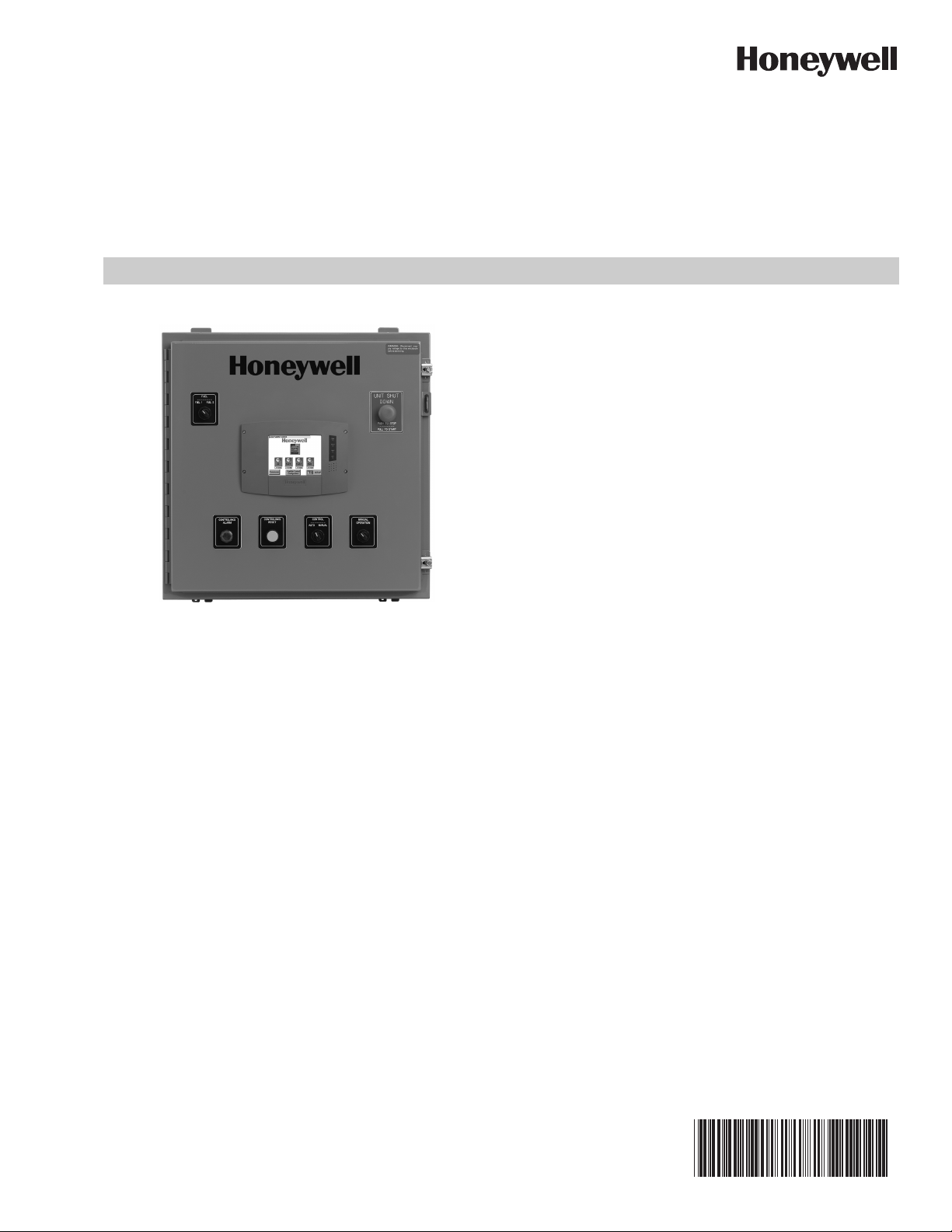
The Honeywell YP7999A1000 ControLinks Fuel Air Ratio
Control Panel is a packaged, pre-wired panel that includes the
R7999A ControLinks controller for linkageless fuel/air ratio
control. The included S7999D color touchscreen interface
allows commissioning of the ControLinks system as well as
monitoring and control, all with user-friendly menus. On board
selector switches, buttons and alarm lights are included for
customer convenience. The ML7999A2001 universal direct
coupled actuators are purchased separately.
This document provides installation instructions and operation
information. Other applicable publications are:
— 65-0238, R7999 ControLinks Controller
— 65-0240, Q7999A ControLinks Universal Wiring Sub-
base
— 65-0239, ML7999A Universal Parallel-Positioning
Actuator
— 65-0321, S7999D1048 System Display
SPECIFICATIONS
Electrical Ratings
100 – 120 Vac, 50/60 Hz, 3 Amps
For individual ratings, see component literature for details.
Environmental Ratings
Enclosure: NEMA 12.
For individual ratings, see component literature for details.
Humidity
Install the panel where the relative humidity never reaches the
saturation point. The relay module inside the panel is
designed to operate in a maximum 85 percent relative
humidity continuous, non-condensing, moisture environment.
Vibration
Do not install the panel where it could be subjected to vibra-
tion in excess of 0.5G continuous maximum vibration.
General
Overall panel size: 24 in. high x 24 in. wide x 8 in. deep
(excluding door and door mounted components)
Panel weight: approx. 64 pounds
Mounting holes are 0.44 in. typical diameter, 18 in. on center.
66-2060-01
Page 2
YP7999A1000 CONTROLINKS™ FUEL AIR RATIO CONTROL PANEL
WARNING
WARNING
CAUTION
WARNING
Approvals
Components are individually approved by the nationally rec-
ognized agencies. Please see component literature for
details. The panel has UL 508A flame control panel
approval. Panel is assembled and wired to the UL Standards.
INSTALLATION
When Installing This Product…
1. Read these instructions and the appropriate product lit-
erature carefully. Failure to follow them could damage
the product or cause a hazardous condition.
2. Refer to the installation manuals and wiring diagrams
provided with this panel for the embedded products.
3. Check the ratings given in the instructions and on the
product to make sure that the product is suitable for your
application.
4. Installer must be a trained, experienced combustion service technician.
5. Disconnect the power supply before beginning installation to prevent electrical shock and equipment damage.
More than one disconnect may be involved.
6. All wiring must comply with the National Electric Code
(NEC) and any applicable local electrical codes, ordinances and regulations.
7. After installation is complete, check out product operation as provided in the appropriate product installation
instructions.
Fire or Explosion Hazard. Can cause severe injury,
death or property damage.
To prevent possible hazardous burner operation, verify
safety requirements each time a controller is installed
on a burner.
WIRING
Electrical Connections
1. Refer to the appropriate product data sheet for details.
2. Wire size and length will vary, depending on the compo-
nent. Refer to the component literature for specific wire
lengths, sizes and type recommendations.
3. Wire according to specifications, following all local ordinances and requirements.
4. Field knockouts are required for the wiring. When drilling holes, take care to protect the electronics from metal
pieces and debris.
IMPORTANT
Run line voltage and low voltage wiring in separate
conduit to avoid signal interference.
Carefully check field wiring and terminal designations in this document and the associated wiring diagram. They are different from those of the individual
components.
Panel Inspection
After mounting and wiring, but before powering the panel,
inspect all internal panel wire connections. Each panel is fully
tested at the factory; however, wires may loosen during transit.
Verify that all internal wire connections are secure from the
Q7999 subbase to the components mounted on the door and
the S7999D touchscreen interface.
Final Wiring Check and Static Checkout
All wiring shall be in accordance with the National Electric
Codes (NEC) and local electrical codes.
1. Check the power supply circuit. The voltage and frequency must match the specification listed.
2. Check wiring terminations and routing to ensure proper
connections.
3. Follow any system checkout recommendations for individual components as found in the component literature.
4. Restore power to the panel.
Electrical Shock Hazard. Can cause serious injury,
death or equipment damage.
Disconnect the power supply before beginning wiring
to prevent electrical shock, equipment and control
damage. More than one disconnect may be involved.
Ground Connection
Earth ground is required for proper operation of the
ControLinks system. The earth ground must be capable of
conducting enough current to blow the fuse or breaker in the
event of an internal short. Ensure the panel is bonded to a
substantial earth ground. Make sure that mechanically
tightened joints along the ground path are free of
nonconductive coatings and protected against corrosion on
mating surfaces.
66-2060—01 2
Test each limit and interlock to ensure system
operates correctly as defined in the 7800 Series
“Checkout and Test” document (Form #65-0229).
Explosion and Electrical Shock Hazard.
Can cause serious injury, death or equipment
damage.
1. Close all manual fuel shutoff valves before starting
these tests.
2. Use extreme care while testing the system. Line voltage
is present on most terminal connections when power is
on.
3. Replace all limits and interlocks that are not operating
properly. Do not bypass limit and interlocks.
Page 3

YP7999A1000 CONTROLINKS™ FUEL AIR RATIO CONTROL PANEL
TROUBLESHOOTING
System Diagnostics
The S7999D touchscreen interface indicates the current fault and keeps a fault history log. The R7999 ControLinks control and
the ML7999A Universal Parallel-Positioning Actuator also have LED fault blink codes. Refer to the appropriate product instruction
sheet for further troubleshooting information and diagnostic codes.
FIELD WIRING
Table 1. Field Wiring and Terminal Designation1.
To Connecting
Terminal #
2
1
2 L2 Panel neutral
GND Panel ground
3
4
3
2
3
GND
9 HFP High Fire Proven output from ControLinks controller to burner control
10 LFP Low Fire Proven output from ControLinks controller to burner control
11 HF High Fire drive command input from burner controller
12 MV Main Valve command input from burner controller
13 LF Low Fire drive command input from burner controller
14 LCI Limit Control Input from burner limit string, including on/off control, LWCO, high-limit, etc…
15 LCO Limit Control Output from ControLinks controller to burner control demand/interlock inputs
3,4
200
3,4
201
3,4
202
3,4
203
3,4
204
3,4
GND
3,4
205
3,4
206
3,4
207
3,4
208
3,4
209
3,4
GND
3,4
210
3,4
211
3,4
212
3,4
213
3,4
214
3,4
GND
Device Description
L1 Panel power 120Vac Power Supply, 3A Max.
L1 power to circuit breaker.
Provide disconnect means and overload protection as required.
L1 L1 customer convenience wire point – provided for 4 actuators – 120Vac, 50/60Hz
L2 L2 customer convenience wire point – provided for 4 actuators
Panel ground GND customer convenience wire point – provided for 4 actuators
DR1 Air Actuator DR1 command input
DR2 Air Actuator DR2 command input
CW Air Actuator potentiometer CW output
S Air Actuator potentiometer S output
CCW Air Actuator potentiometer CCW output
Ground Air Actuator ground
DR1 Fuel 1 Actuator DR1 command input
DR2 Fuel 1 Actuator DR2 command input
CW Fuel 1 Actuator potentiometer CW output
S Fuel 1 Actuator potentiometer S output
CCW Fuel 1 Actuator potentiometer CCW output
Ground Fuel 1 Actuator ground
DR1 Fuel 2 Actuator DR1 command input
DR2 Fuel 2 Actuator DR2 command input
CW Fuel 2 Actuator potentiometer CW output
S Fuel 2 Actuator potentiometer S output
CCW Fuel 2 Actuator potentiometer CCW output
Ground Fuel 2 Actuator ground
3 66-2060—01
Page 4

YP7999A1000 CONTROLINKS™ FUEL AIR RATIO CONTROL PANEL
Table 1. Field Wiring and Terminal Designation
1
. (Continued)
To Connecting
Terminal #
3,4
215
3,4
216
3,4
217
3,4
218
3,4
219
3,4
GND
Device Description
DR1 FGR/4th Channel Actuator DR1 command input
DR2 FGR/4th Channel Actuator DR2 command input
CW FGR/4th Channel Actuator potentiometer CW output
S FGR/4th Channel Actuator potentiometer S output
CCW FGR/4th Channel Actuator potentiometer CCW output
Ground FGR/4th Channel Actuator ground
223 XmA+ Auxiliary 4-20mA+ input from Stack/Water temperature sensor (used for low fire hold)
220 XmA- Auxiliary 4-20mA- input from Stack/Water temperature sensor (used for low fire hold)
224 CmA+ 4-20mA+ input from Firing Rate control
225 CmA- 4-20mA- input from Firing Rate control
5
231
5
232
5
228
1
Carefully check field wiring and terminal designations in this document and the associated wiring diagram. They are different
COM 2 A S7999D COM 2 Modbus A / Data + terminal
COM 2 B S7999D COM 2 Modbus B / Data - terminal
COM 2 GND S7999D COM 2 Modbus C / Ground terminal
from those of the individual components.
2
The circuit protection incorporated into this control panel is designed to serve as supplemental protection only. It is the responsibility of the end user to provide appropriate protection on the service to this control panel. Refer to the National Electric Code
and UL standard 1077 for more information on this subject. Use 16 AWG MTW wire.
3
Low voltage wire to the firing rate actuators must be run in separate conduit. Line voltage wiring to actuators may be obtained
from terminals 4, 2 and GND or provided by customer. Run line voltage wires in separate conduit. Refer to the ML7999A product sheet for details.
4
Connect the shield ground of the ML7999A actuator(s) to the earth ground strip provided in the Q7999 universal subbase, on
the low voltage side. Connect the shield at the controller end only. Refer to the ML7999A product sheet for details.
5
COM 2 on the S7999D is wired to field terminals for customer use. Customer may wire an existing Modbus-capable RM78xxL
burner control and/or Modbus-enabled UDC2500/3200/3500 controls in a daisy-chain fashion to the customer terminals for display on the S7999D. Refer to the S7999D, S7800A or S7810M and UDC control product manuals for further information on wiring and S7999D display set-up.
6
Installation, operation and maintenance shall conform with National Fire Protection Association standards, national and local
codes and authorities having jurisdiction.
7
For detailed device wiring information, refer to the R7999, Q7999A, ML7999A and S7999D1048 product sheets.
66-2060—01 4
Page 5

YP7999A1000 CONTROLINKS™ FUEL AIR RATIO CONTROL PANEL
TWIST TO START
PUSH TO STOP
M34890
24 (610)
24
(610)
MANUAL
OPERATOR
5K OHMS
MANUAL
AUTO
SS103
CONTROL
CONTROLINKS
RESET
CONTROLINKS
ALARM
LT104 PB114
FUEL
SS104
WARNING
ADVERTISEMENT
P9100
Fig. 1. Panel front dimensions in in. (mm).
Table 2. Wire Code.
Function Color AWG
120 VAC (HOT) RED 16 (MTW)
120 VAC (NEUTRAL) WHITE 16 (MTW)
GROUND GREEN 16 (MTW)
DRY CONTACTS YELLOW 16 (MTW)
VDC BLUE 16 (MTW)
24 VAC BROWN 16 (MTW)
TYPE K THERMOCOUPLE YELLOW/RED 20 (POLYVINYL)
FSG RESET/CONTROLINKS RESET/POTENTIOMETER BELDEN 8760 18 AWG TWISTED PAIR
ACTUATOR INTERFACE BELDEN 9535 24 AWG, 5 CONDUCTOR
DISPLAY TO TERMINAL STRIP BELDEN 9535 24 AWG, 5 CONDUCTOR
DISPLAY COM1 & COM2 (FROM TERM STRIP TO DEVICES) BELDEN 8770 18 AWG, 3 CONDUCTOR
TEMP CTRL MODBUS BELDEN 8770 18 AWG, 3 CONDUCTOR
5 66-2060—01
Page 6

YP7999A1000 CONTROLINKS™ FUEL AIR RATIO CONTROL PANEL
M34891
Fig. 2. Wiring diagram (part 1).
66-2060—01 6
Page 7

(L) (N)
M34892
YP7999A1000 CONTROLINKS™ FUEL AIR RATIO CONTROL PANEL
Fig. 3. Wiring diagram (part 2).
Wiring Diagram Key Wiring Notes
Indicates terminals and wiring in control panel
(main terminal block).
Indicates external wiring.
Indicates terminals in valves.
Indicates component terminals.
1. The circuit protection incorporated into this control
panel is designed to serve as supplemental protection
only. It is the responsibility of the end user to provide
appropriate protection on the service to this control
panel. Refer to the National Electric Code and UL Standard 1077 for more information.
2. Wire to the firing rate actuator must be run in separate
conduit.
7 66-2060—01
Page 8

YP7999A1000 CONTROLINKS™ FUEL AIR RATIO CONTROL PANEL
21 (533)
21
(533)
3A
FU100
FU121
.5A
1
FUEL/AIR
CONTROL
SPARE
SPARE
SPARE
SPARE
SPARE
SPARE
M34893
SPARE
3. Ground shield to subbase earth ground screw on low
voltage side of subbase.
4. Installation, operation, and maintenance shall conform
with National Fire Protection Association standards,
national and local codes, and authorities having jurisdiction.
Fig. 4. Equipment mounting panel dimensions in in. (mm).
Automation and Control Solutions
Honeywell International Inc.
1985 Douglas Drive North
Golden Valley, MN 55422
customer.honeywell.com
® U.S. Registered Trademark
© 2013 Honeywell International Inc.
66-2060—01 M.S. 06-13
Printed in United States
 Loading...