

Page 1
1
95-3 Wireless room thermostats, wired valves, wireless
TPI boiler control
95-1 Wireless room thermostats, wired valves, wired TPI
boiler control
95-2 Wireless room thermostats, wired valves, OpenTherm 2
wire boiler control
Y9520Z Sundial RF² Pack 5
INSTALLATION INSTRUCTIONS
50047644-006 A
Application
This pack provides a wireless control solution for adding 2 wireless room
thermostats to heating systems, in order to split the heating system
into 2 separate zones and ensure compliance with the latest Building
Regulations.
Pack Contents & Product Descriptions
1 x ST9520C1005 Wireless enabled 7 day programmer with 2
output control relays for switching boilers, pumps
and zone valves in heating systems. It requires
permanent mains 230Vac power.
2 x DTS92E1020 Wireless digital room thermostat with energy
saving ECO function. It operates on 2 x AA alkaline
batteries, giving a battery life of at least 2 years
under typical operating conditions.
2 x table stand for DT92E (optional)
Other Honeywell products, not supplied in this pack, may be required
for a complete installation, depending on the application. For example
BDR91T1004 relay box. See Schematic System Layouts (below) or refer
to www.honeywelluk.com for full details.
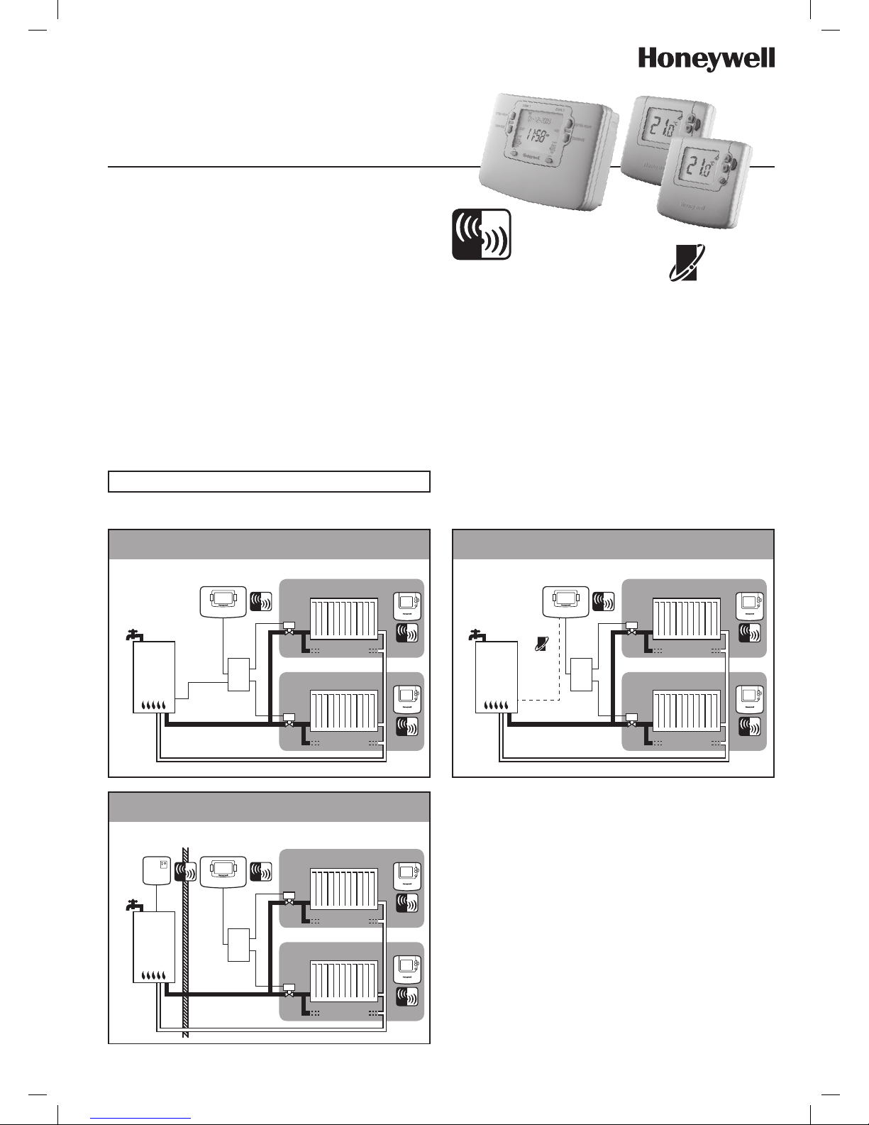
Schematic System Layouts
System Operation
DT92E and ST9520C use 2-way communication on an 868MHz radio
frequency (RF) band to control the heating system.
ST9520C operates as the control hub of the system and the DT92E
thermostats are free to be positioned in suitable locations in the 2
separate heating zones.
This functionality is ideal for upgrading existing systems without a room
thermostat to ensure compliance with Building Regulations. It is also ideal
for refurbished systems, where running mains cable from the programmer
to the thermostats and back to the boiler is difficult or impractical.
There are various options for how to connect to the boiler. The simplest
is a direct 230Vac connection. If the boiler supports OpenTherm
communications technology, it is possible to control it using a 2-wire
connection from the ST9520C OpenTherm terminals. If the boiler is
located remotely, it is possible to send the switching signal from the
ST9520C to a remote located BDR91T relay box.
2-way wireless
communication
Honeywell
Sundial RF² is a registered
trademark of Honeywell Inc.
OpenTherm®
communication
V4043H
ZONE 1
ZONE 2
V4043H
Radiator(s)
Radiator(s)
DT92E
DT92E
ST9520C
Junction
Box
Junction
Box
Junction
Box
Hot Water
V4043H
ZONE 1
ZONE 2
V4043H
Radiator(s)
Radiator(s)
DT92E
DT92E
ST9520C
Boiler
Hot Water
BDR91T
V4043H
ZONE 1
ZONE 2
V4043H
Radiator(s)
Radiator(s)
DT92E
DT92E
ST9520C
Boiler
Hot Water
OpenTherm®
2-wire connection
This document is to be left with the user
Page 2
2
The RF link between the Room Thermostats (DT92E) and the Zone
Programmer (ST9520C) in Honeywell system packs is pre-configured
at the factory and therefore all units should be installed at the same site.
• Ifproducts fromindividual systempacks areseparated, ormixed
with other pre-configured system packs during installation, or a
faulty unit is being replaced, the desired units must be specially
configured to allow them to communicate with each other. This
process is called Binding. Please refer to section 6 Binding / Re-
binding Procedure.
• DT92E or ST9520Cwillnotcommunicate with other RF products
that use different frequencies or communications protocols.
• TheDT92E roomthermostatrequires nopower sourceotherthan
the batteries provided.
• The ST9520C Programmer requires a permanent 230V~ supply.
• The ST9520C Programmer should be installed and powered up
before commencing installation on the DT92E room thermostats.
• IfcontrollingtheboilerviaanOpenThermconnection,theST9520C
must be configured to provide this form of output (see Section
4 System Configuration)
• Ifthe boilerisbeingswitchedusingaremote relaybox(BDR91T)
the relay box is not supplied in this pack and will require to be bound
to ST9520C (see Section 6 Binding / Re-binding Procedure)
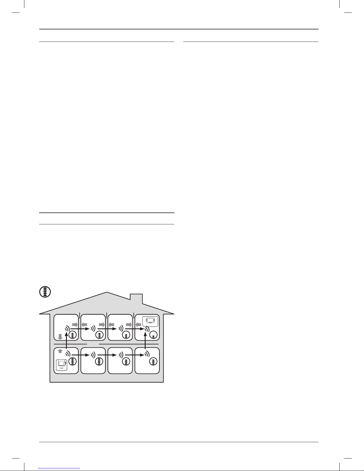
Within a typical house two RF products should communicate reliably
within a 30m range. It is important to take into consideration that walls
and ceilings will reduce the RF signal. The strength of the RF signal
reaching the Programmer depends on the number of walls and
ceilings separating it from the room thermostat, as well as the building
construction - the diagram below illustrates an example of typical
signal strength reduction. Walls and ceilings reinforced with steel or
plasterboard walls lined with metal foil reduce the RF signal significantly
more.
RF Signal Propagation
Installation Notes Installation Sequence: Step by Step
Typical example of Building Fabric Signal losses
= Signal Strength
Wall Wall Wall
Ceiling
Max. Signal Length 30 metres
Section Page
1 INSTALLING THE ST9520C PROGRAMMER
1.1 Mounting ST9520C .................................................................. 3
1.2 ST9520C Mounting options ..................................................... 3
1.3 Wiring ST9520C ....................................................................... 3
1.4 ST9520C Final Assembly ......................................................... 3
1.5 ST9520C Internal Wiring .......................................................... 4
1.6 Wiring Diagrams ...................................................................... 4
1.7 Replacing Other Time Controls ............................................... 5
1.8 Powering Up ST9520C ............................................................ 5
2 INSTALLING THE DT92E ROOM THERMOSTAT
2.1 Locating DT92E ....................................................................... 6
2.2 Powering Up DT92E ................................................................ 6
2.3 DT92E Signal Strength Test ..................................................... 6
2.4 Mounting DT92E ...................................................................... 7
2.5 Separating DT92E from its Mounting Plate .............................. 7
3 INSTALLING THE BDR91T WIRELESS RELAY BOX
3.1 Locating the BDR91T............................................................... 8
3.2 BDR91T Mounting Options ...................................................... 8
3.3 Wiring BDR91T ........................................................................ 8
3.4 BDR91T Final Assembly .......................................................... 8
4 SYSTEM CONFIGURATION: ST9520C
4.1 ST9520C Installer Modes......................................................... 9
4.2 Boiler Service Reminder / Shut-down Feature ......................... 9
4.3 Installer Setup ........................................................................ 10
4.4 Installer Setup Flowchart ....................................................... 11
4.5 OpenTherm Setup and Information Display .......................... 11
4.6 Set Service ............................................................................. 12
4.7 Change PIN ........................................................................... 14
4.8 What the User Will See When a Service is Due ..................... 14
4.9 Resetting the Service Timer Function .................................... 14
5 SYSTEM CONFIGURATION: DT92E
5.1 DT92E Installer Mode ............................................................ 15
6 BINDING / RE-BINDING PROCEDURE
6.1 Binding................................................................................... 16
6.2 ST9520C Guided Binding Menu ............................................ 16
6.3 Replacing Devices or Changing the Application .................. 16
6.4 Binding Menu Display............................................................ 17
6.5 How to Bind DT92E to ST9520C ............................................ 17
6.6 How to Bind BDR91T to ST9520C ......................................... 18
6.7 How to Test BDR91T Signal Strength .................................... 19
7 COMMISSIONING THE SYSTEM
7.1 System Test Checklist ............................................................ 20
7.1 Completion Checklist ............................................................. 20
Page 3
3
For best performance, install in an open space. Leave at least 30cm
distance from any metal objects including pipes and the boiler housing.
After locating the DT92E room thermostats, use the Signal Strength
Test shown on Page 7 to determine if there is a reception problem.
If problems persist, it is recommended that this metal wallbox is
replaced by an equivalent plastic wallbox.
The Programmer should be mounted at a level where the display can
be seen clearly, (compliance with Building Regulations part M requires
a height of 1.2m from the floor) and the ambient temperature is within
the range of 0 to 40°C. The ST9520C is for use in normal domestic
environments.
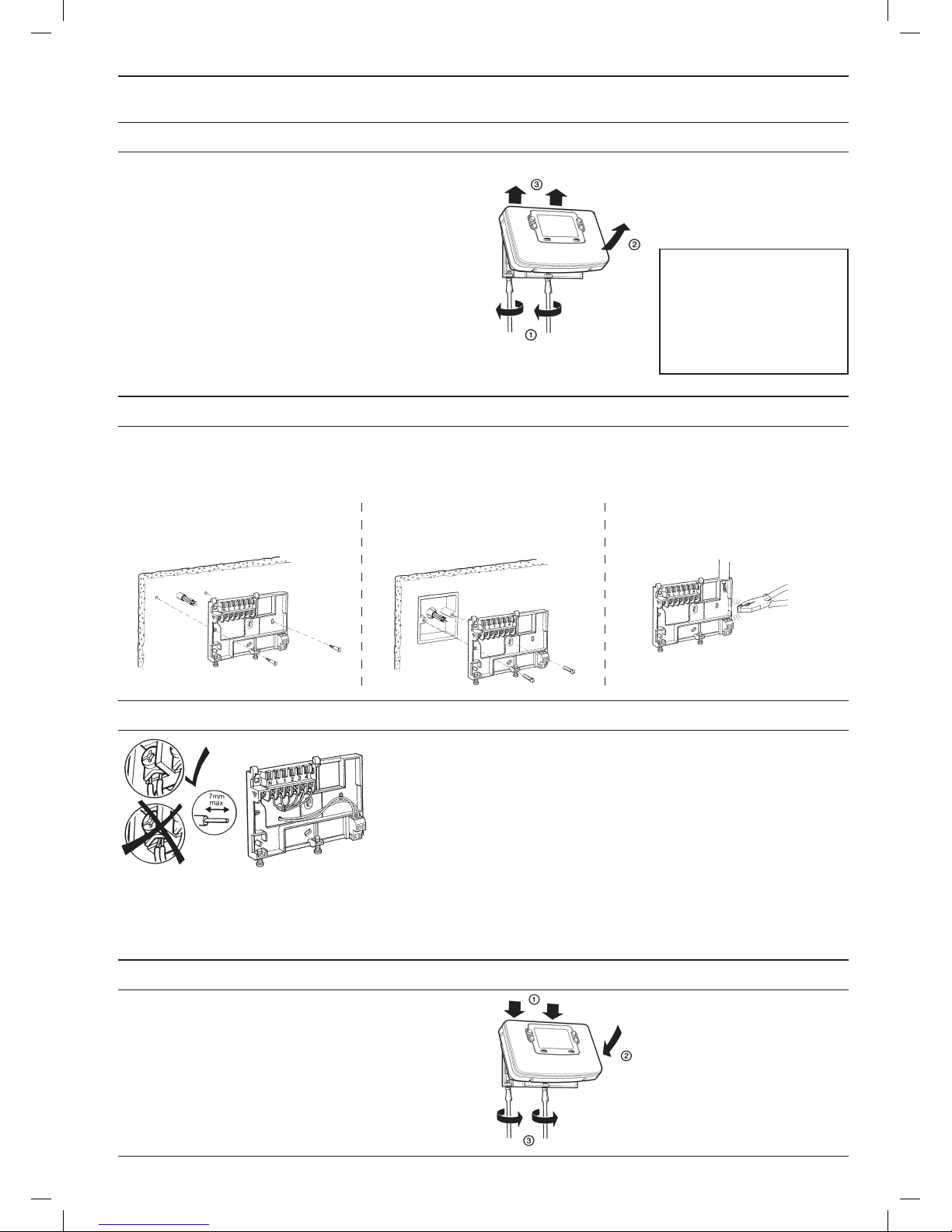
To remove the unit from the wall-plate,
slacken the two securing screws at the
bottom of ST9520C and hinge the unit
up to separate the two halves.
1
INSTALLING THE ST9520C PROGRAMMER
1.1 Mounting ST9520C
CAUTION
Isolate power supply and make
safe before wiring the unit to
prevent electric shock and
equipment damage. Installation
should be carried out by a qualified
electrician or competent heating
engineer.
Recommended clearance distances:
Above wallplate: 110mm
Below wallplate: 100mm
Left/right of wallplate: 10mm
a. Surface mounting concealed wiring b. Flush switchbox
Fixing holes are spaced to suit
BS4662 requirements
c. Surface mounting with
surface wiring in mini trunking
Clip the unit onto the hinges on the top of the wallplate and hinge down
into position. Tighten the two securing screws using a screwdriver.
Switch on the power – the unit will now be operating according to the
built-in programme.
Note: the ST9520C is supplied with a factory set clock for faster
installation.
Refer to Y9520Z User Guide for programming details.
Ensure the mounting surface is supporting and fully covers the wiring wall-plate.
ALL WIRING MUST BE IN ACCORDANCE WITH IEE REGULATIONS.
THIS UNIT IS FOR FIXED WIRING ONLY.
A switch, having contact separation of at least 3mm in all poles must be
incorporated in the fixed wiring as a means of disconnecting the supply.
The unit is a Class II (double insulated) device. A parking terminal is
provided for external earth continuity.
The system must be appropriately fused. A fuse rated at no more than 3
Amps should be installed.
The unit has 4 knockouts for surface wiring. Care must be taken to
ensure that the cable or mini-trunking completely fills the knockout hole
without leaving any gaps.
If the OpenTherm 2 wire connection is used, maintain as large a separation
as possible between these wires and any mains voltage wiring.
EMC compliance considerations
Keep AC mains supply/load cables separate from signal wiring.
Refer to Code of Practice standards EN61000-5-1 and -2 for guidance.
1.2 ST9520C Mounting Options
1.3 Wiring ST9520C
1.4 ST9520C Final Assembly
Page 4
4
Notes
1. DT92E is completely wireless and so is not shown connected on
these wiring diagrams.
2. The ST9520C is a Class II (double insulated) device. A parking
terminal is provided for earth wiring continuity, if required.
3. The OpenTherm boiler connection (diagram 95-2) is a low voltage
polarity-free connection and is not for 230V~ mains voltages.
4. The BDR91T Relay Box (diagrams 95-3) requires a permanent
230V~ supply.
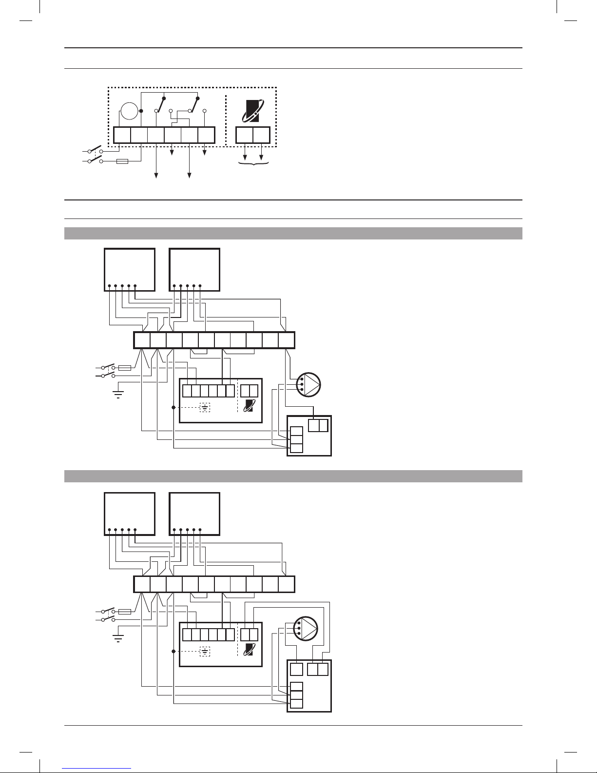
1.6 Wiring Diagrams
1.5 ST9520C Internal Wiring
Clock
N L 1 2 3 4
3 AMPS MAX
Zone1
OFF
Zone2
OFF
Zone1
ON
Zone2
ON
N
L
OFF ON OFF ON
230V~
50...60Hz
A B
OpenTherm low voltage
output to boiler.
NOT MAINS
95-1 Wireless room thermostat, wired valves, wired TPI boiler control
95-2 Wireless room thermostat, wired valves, OpenTherm 2 wire boiler control
V4043H
2 PORT ZONE VALVE
ZONE 2
BLUE
G/YELLOW
BROWN
ORANGE
GREY
V4043H
2 PORT ZONE VALVE
ZONE 1
BLUE
G/YELLOW
BROWN
ORANGE
GREY
3 AMPS
MAX
L
N
230V~
50...60Hz
BOILER
PUMP
L
N
E
ST9520C
*NOTE 2
N
L 1 2 3 4AB
T1
L
N
E
1 2 3 4 5 6 7 8 9 10
V4043H
2 PORT ZONE VALVE
ZONE 2
BLUE
G/YELLOW
BROWN
ORANGE
GREY
V4043H
2 PORT ZONE VALVE
ZONE 1
BLUE
G/YELLOW
BROWN
ORANGE
GREY
3 AMPS
MAX
L
N
230V~
50...60Hz
BOILER
PUMP
L
N
E
ST9520C
*NOTE 2
N
L 1 2 3 4AB
T1
T2
PL
L
N
E
1 2 3 4 5 6 7 8 9 10
Additional notes
a. Orange wires from zone valves are ‘parked’ for
convenience.
b. Pump live is taken from boiler. If boiler does not
provide this output, connect live input to pump from
terminal 10
Page 5

5
95-3 Wireless room thermostat, wired valves, wireless TPI boiler control
Check the unit powers up correctly and that the display does not remain blank.
ST9520C must be powered up before the DT92E thermostats are installed, so that the signal strength tests can be conducted.
The initial signal strength test will verify that both units have each others addresses in their memory, and can therefore communicate. The process of
writing respective addresses into memory is called BINDING.
ST9520C is supplied with its own wiring back-plate. As this is for new or upgraded installations it is recommended this is used, and it MUST be used
for OpenTherm applications (95-3).
ST9520C may mount on the back-plate of existing time controls, but it is likely major wiring changes will be required for compatibility with the plumbing
and controls changes. Refer to the Honeywell Technical Help Desk for advice.
1.8 Powering Up ST9520C
1.7 Replacing Other Time Controls
1.6 Wiring Diagrams (cont.)
Additional notes
a. Orange wires from zone valves are ‘parked’ for
convenience.
b. Pump live is taken from boiler. If pump is located next
to zone valves, take the pump N and E from the 10-way
junction box (terminals 2 & 3 respectively) and the pump
switched Live from terminal 10.
V4043H
2 PORT ZONE VALVE
ZONE 2
BLUE
G/YELLOW
BROWN
ORANGE
GREY
V4043H
2 PORT ZONE VALVE
ZONE 1
BLUE
G/YELLOW
BROWN
ORANGE
GREY
3 AMPS
MAX
5 AMPS
MAX
L
N
L
N
230V~
50...60Hz
230V~
50...60Hz
BOILER
PUMP
L
N
E
ST9520C
BDR91T
*NOTE 2
N
L 1 2 3 4
N
L L
A
B
T1
T2
PL
L
N
E
1 2 3 4 5 6 7 8 9 10
A-B:5(3)A
A-C:5(3)A
A
B C
Page 6
6
This pack contains 2 x DT92E room thermostats for location in each control zone. The DT92E for Zone 1 has
a zone ID label number 1 under the battery cover. The other DT92E has zone ID label 2. These thermostats
must be located in the correct zone to ensure the correct valve is operated in response to their commands.
For best performance, install each DT92E in an open space where it can sense the room temperature, and
where the signal strength is high.
The Room Thermostats can be mounted on a wall or on the optional table stand. Do not mount on metal
wall-boxes.
Leave at least 30cm distance from any metal objects and at least 1 metre from any other electrical equipment.
Select the preferred location and test the Signal Strength before installation.
2
INSTALLING THE DT92E ROOM THERMOSTATS
2.1 Locating DT92E
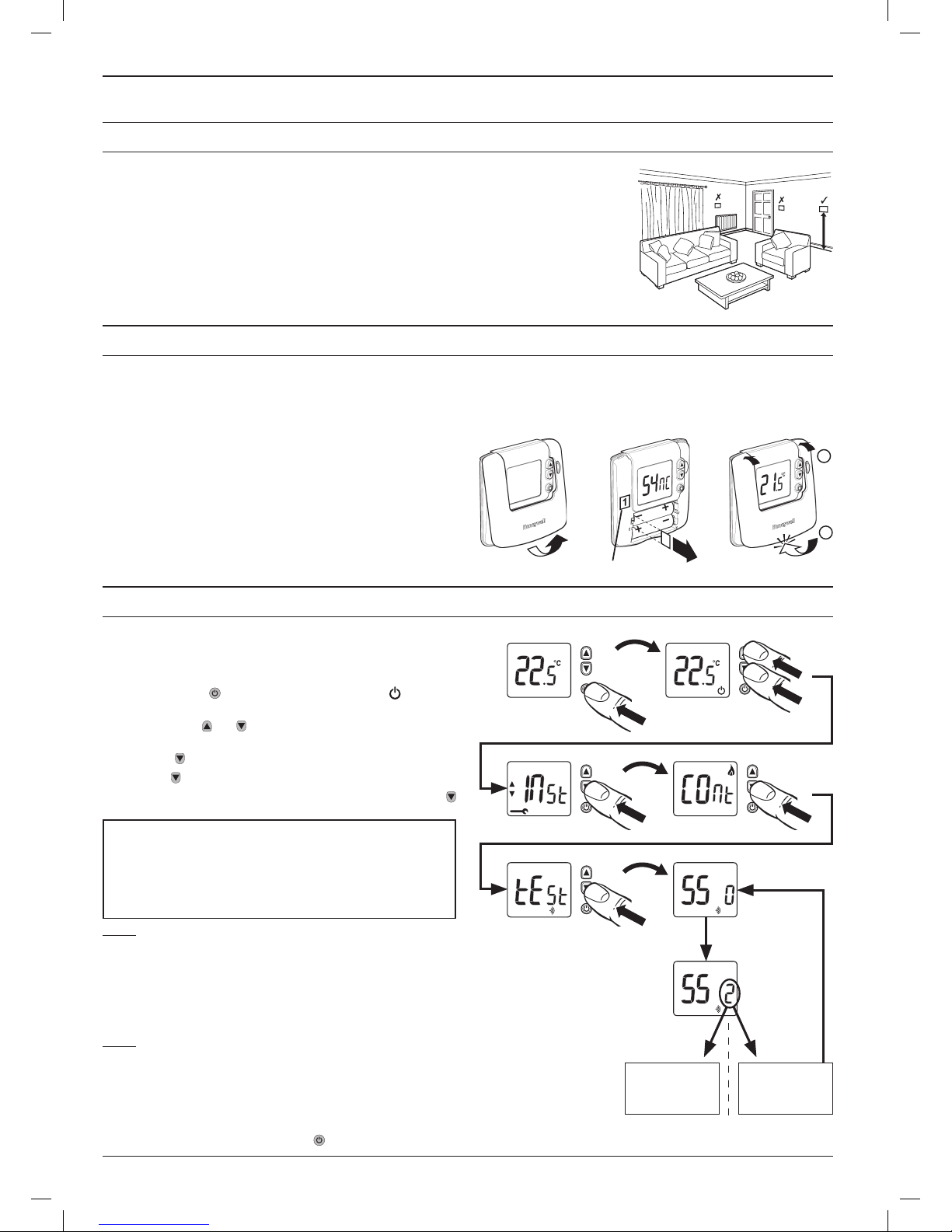
DT92E is supplied in the pack with the mounting plate separated from the rest of the unit for ease of installation. The next sequence of operations
should be done before mounting DT92E onto its mounting plate.
First hold DT92E between 1 and 2 meters away from ST9520C. To power it up, unclip the battery cover and then remove the paper tab that isolates
the batteries from their contacts. When the display powers up the battery cover should be clipped back on.
Immediately on power up, DT92E will try to communicate and
synchronise with ST9520C. This process may take up to 4 minutes, and
will be indicated by the word ‘Sync’ on the DT92E display.
When ‘Sync’ disappears from the display, DT92E is ready for a test of
the RF signal strength between it and the ST9520C programmer.
Now go to section 2.3 to conduct the Signal Strength Test.
2.2 Powering Up DT92E
1
2
Honeywell 2-way RF communications allows signal strength testing to
ensure DT92E can be positioned in the best possible location.
To enter Signal Strength Test:
a. Hold down the button for 2 seconds until the symbol is
displayed.
b. Hold down the
and
buttons together for 3 seconds until ‘Inst’
appears in the display.
c. Press the button (‘Cont’ is now displayed)
d. Hold the button for 3 seconds to enter Test mode.
e. Signal Strength Test is entered from Test mode by holding the
button for 3 seconds, until the display shows ‘SS’.
Step 1
Hold DT92E between 1 and 2 meters away from ST9520C and check the signal strength is high
(3 or more). This confirms the two units are in the condition they left the factory and are bound
together, and you can move to Step 2.
If the signal strength is shown as 0, the units are possibly not bound together. Go to the
section 6 Binding / Rebinding, follow the procedure there, and then repeat the complete
Signal Strength Test sequence.
Step 2
Whilst staying in Signal Strength Test mode, take the DT92E to the preferred location. Wait for
10 seconds and check the signal strength is 3 or more. If so, the DT92E is ready to mount.
If the signal strength is less than 3, re-position the room thermostat within the local area +/- 1 or
2m to see if the signal strength improves. If this fails, try to reduce the range/distance between
the room thermostat and the ST9520C.
2.3 DT92E Signal Strength Test
3 s
2 s
3 s
Poor signal,
reposition Room
Thermostat.
Strong signal,
proceed to
mount the Room
Thermostat.
10 s
= 0, 1, 2= 3, 4, 5
3 s
ST9520C measures the strength of the DT92E signal every 5-10
seconds and will communicate this to DT92E as a number between
0 and 5. The value drops to 0 briefly as each new signal strength
measurement is made.
A signal strength of 3 or more is recommended to ensure reliable
communications.
Exit Signal Strength Test by holding the button for 5 seconds. The DT92E will timeout of this mode after 10 minutes.
Zone ID Number (1 or 2)
1.2m
Page 7

7
2.5 Separating DT92E from its Mounting Plate (if required)
DT92E can be mounted (a) directly on a wall, or (b) on the optional table stand provided.
Wall mounting is recommended as it ensures a position of high signal strength can be maintained.
If the DT92E requires to be separated from its mounting plate, follow the simple steps shown below.
a. For wall mounting, install the mounting plate first, then follow
steps 1, 2 and 3 to hinge the front piece on, as shown in the
diagrams.
b. If the optional table stand is to be used, first assemble the two
pieces together as shown. Next follow steps 1, 2 and 3 to hinge
the DT92E front piece onto its mounting plate, and mount the unit
onto the table stand.
1
2
= N
o
6
3
2.4 Mounting DT92E
2
1
3
Page 8

8
If the heating boiler is located remotely it is possible to control it using a wireless relay box BDR91T1000. This is not supplied in this pack and must
be purchased separately. After installation it must be bound (paired) to the ST9520C timer and then the signal strength should be verified to ensure
the location chosen is suitable.
The BDR91T Relay Box requires a permanent 230V~ supply.
Isolate power supply and make safe before wiring the
unit to prevent electric shock and equipment damage.
Installation should be carried out by a qualified
electrician or competent heating engineer.
For wiring schematics please refer to diagram 95-3 on page 5.
EMC compliance considerations
Keep AC mains supply/load cables separate from signal wiring.
Refer to Code of Practice standards EN61000-5-1 and -2 for guidance.
1
2
< 7mm Ø
> 7mm Ø
a. Mounting on a wall box b. Surface mountingRemoving the BDR91T cover
Replacing the BDR91T coverWire preparation
= M3.5
= N
o
6
1.5-2.5mm²
6mm max.
2
1
For best performance install in an open space. Leave at least 30cm distance from any metal
objects including wall boxes and boiler housing. Do not mount on metal wall boxes.
The BDR91T needs to be positioned in a location where the RF signal strength from ST9520C is
high. The simplest way to identify such a location in advance is to use the signal strength feature
on DT92E, because DT92E can be moved around freely.
a) Remove one DT92E from its mounting plate (section 2.5)
b) Enter signal strength test (section 2.3)
c) Identify a location close to the boiler where the signal strength is 3 or more.
d) After BDR91T is mounted and wired in this location, the signal strength it is receiving can be
verified using its own signal test (section 6.7)
e) Remember to re-attach DT92E to its mounting plate.
Ensure the mounting surface is supporting and fully covers the
backplate and mount to the surface using the screw holes provided.
An alternative pair of mounting holes is also available.
Unclip the front cover and hinge it
away to reveal the wiring backplate.
Insert the hinges and close
the cover until it clips closed
at the bottom.
Ensure only the correct
gauge of wire is used and
tightened securely into the
correct terminal.
NOTE: The BDR91T contains no user serviceable parts. It should be
opened and installed by a qualified installer only.
WARNING: Electrostatic sensitive device! Do not touch the circuit board.
3
INSTALLING THE BDR91T WIRELESS RELAY BOX (IF REQUIRED)
3.2 BDR91T Mounting Options
3.1 Locating the BDR91T
3.3 Wiring BDR91T
3.4 BDR91T Final Assembly
CAUTION
Page 9

9
ST9520C has 4 Installer Modes that enable the product to be customized for the application and for the needs of the User. Each adjustable feature is
called a Parameter, and is represented by a number or letter ID and a value. The Modes are:-
• InstallerSetup
Installer Setup allows features to be adjusted to suit user lifestyles or preferences, for example; backlight operation, automatic time-change, and
selection of the default time programme. It is entered by a combination of button presses.
• OpenTherm Setup (and information display)
This mode allows OpenTherm communications to be enabled, the OpenTherm parameters to be configured, and some OpenTherm data from
the boiler to be displayed.
• SetService
This is where the ST9520C Boiler Service Reminder and Shut-down Features can be set. This mode can only be entered by using a 4 digit PIN
code. The factory supplied default PIN code is 0000
• ChangePIN
This mode allows the 4-digit PIN code to be adjusted. It is itself protected by the PIN code. When the code is changed this new code is used to
enter both SET SERVICE and CHANGE PIN modes.
To Enter & Navigate Around the Installer Modes:
a. Ensure the slider is in the RUN position, then press and hold
and buttons together for 8 seconds. Ignore the ‘NOT VALID’
that is displayed for a few seconds. The message ‘SET UP MENU’
will show briefly, to indicate you have entered the Setup menu. The
LoT™ Display will continue to show messages indicating which
Installer Mode is possible to select, for example ‘SET INSTALLER
OK ?’
b. Use the or buttons to navigate to the correct Installer Mode.
c. Use the button to confirm you wish to enter that particular mode.
To Exit Installer Modes:
You can exit the Installer Modes at any time by moving the slider to the next position and then back again to RUN. Any changes that have been
confirmed will be saved and used.
Note: The Installer Modes and the Setup Menu will exit automatically after 10 minutes if the slider is not moved and no adjustments have been made
in this time.
4
SYSTEM CONFIGURATION: ST9520C
4.1 ST9520C Installer Modes
The ST9520C Programmer has a Service feature that can assist Social Housing Landlords to comply with the requirements of Regulation 36 of the
Gas Safety (Installation & Use) Regulations 1998. It is intended as an aid to compliance but should not be used to replace the Landlord’s existing
Servicing procedures.
The ST9520C performs like a standard 2 Zone programmer. In addition it can automatically provide a Service Reminder and can be set to Shut-down
the heating once the gas Boiler Service becomes overdue. This helps to eliminate the potential for an incident to occur after the Landlord’s Safety
Certificate has expired.
The operation of the Service Feature is flexible. The landlord or installer can set the following:
• Theserviceinterval,indays
• Anadvancereminderforthetenant,bycountingdowndaysuntilserviceisdue
• Acontacttelephonenumbertocalltoarrangetheservice–displayedontheLCDscreen
• Howthetimerwilloperatewhentheserviceintervalhasexpired.
The options include:
1. Continued normal operation with a Reminder message
2. Total shutdown of heating
3. “Prompt” mode – shutdown that will allow repetitive manual over-ride for one hour at a time.
The Service feature is configured from a special Installer Mode called ‘SET SERVICE’. Entry into this mode is only possible by entering a unique 4
digit PIN code.
Note: The ST9520C is supplied from the factory with the Service features DISABLED. They need to be enabled from the Installer Modes. See section
4.6 Set Service for details.
4.2 Boiler Service Reminder / Shut-down Feature
Installer Mode LoT™ Display Message
Installer Setup ‘SET INSTALLER OK ?’
OpenTherm Setup ‘SET OPENTHERM OK ?’
Set Service ‘SET SERVICE OK ?’
Change PIN ‘CHANGE PIN OK ?’
Page 10

10
The system can be set up to operate in a variety of different ways to suit the application, or the user lifestyle or preferences.
This setup is done via the ST9520C Installer Setup. The features that can be adjusted are called Installer Parameters, and are listed in the table below,
along with a description of the options that are possible.
* Not used in this system.
** This parameter by default has a value of 1, unless you change any other parameter, when it will change to 0. Set it to 1 to reset all parameters
back to defaults. Some parameters may not be displayed, depending on the settings made for prior parameters.
INSTALLER PARAMETER Parameter
Number
LoT™ Display
Description
Default
Value
Range of Values Description [LoT™ Display Description]
24hr or am/pm clock display. 1 CLOCK MODE 12 12, 24 12 = am/pm display,
24 = 24hr display
[AM PM]
[24 HOUR]
Configure backlight
operation.
2 BACKLIGHT 2 0, 1, 2 0 = off,
1 = on if button pressed,
2 = on continuously
[NO B-LIGHT]
[B-L DELAY]
[B-LIGHT ON]
Enable/disable auto time
change.
3 AUTO TIME 1 0, 1 0 = disabled,
1 = enabled
[NO CHANGE]
[TIME CHANGE]
1-day or 5/2-day or 7-day
operation.
4 UNIT TYPE 7 1, 5, 7 1 = 1-day operation,
5 = 5/2-day operation,
7 = 7-day operation
[1-DAY]
[5-2 DAY]
[7-DAY]
Number of ON/OFFs per
day.
5 ON PERIODS 3 2, 3 2 = 2 on/offs per day,
3 = 3 on/offs per day
[2 PER DAY]
[3 PER DAY]
Select default time
programme.
6 DEF PROFILE A A, b, C A = standard,
b = at home,
C = economy
[PROFILE A]
[PROFILE B]
[PROFILE C]
* Set Hot Water Temperature 8 WATER TEMP 60 40 ... 85°C Hot Water Temperature [SET WATER TEMP]
Optimum start 9 OP START 0 0, 1, 2 0 = no optimum start
1 = delayed start
2 = optimum start on
[NO OP-STRT]
[DELAY-STRT]
[OP-STRT ON]
Optimum start limit
(Only available if OP START
set to 2)
10 STRT LIMIT 1 1, 2, 3 1 = 1 hour
2 = 2 hours
3 = 3 hours
[1 HOUR]
[2 HOURS]
[3 HOURS]
Optimum stop 11 OP STOP 0 0, 1 0 = disabled,
1 = enabled
[NO OP-STOP]
[OP-STOP ON]
Frost protection temperature
12 FROST TEMP 5 5 to 16°C Frost protection temperature [SET FROST TEMP]
Minimum ON/OFF time 13 MIN ON-OFF 1 1, 2, 3, 4, 5 minutes Minimum ON/OFF time [SET MIN ON-OFF]
Cycle rate 14 CYCLE RATE 6 3, 6, 9, 12 Number of boiler cycles [SET CYCLE RATE]
Proportional band width 15 PROP BAND 15
(=1.5°C)
15 … 30
(=1.5 ... 3.0°C)
Control proportional band [SET PROP BAND]
Failsafe mode (loss of RF
communications)
16 COMMS LOSS 0 0, 1 0 = off
1 = on 20%
[HEAT OFF]
[20 PERCENT]
** Reset all parameters 20 PROG RESET 1 0, 1 0 = do not reset
1 = default parameters
[RESET OFF]
[RESET ON]
To Enter Installer Setup:
a. Ensure the slider is in the RUN position, then press and hold the and buttons together for 8 seconds. Ignore the ‘NOT VALID’ that is
displayed for a few seconds. The message ‘SET UP MENU’ will show briefly, followed by ‘SET INSTALLER OK ?’
b. Press the button to take you into the Installer Setup Parameter Menu.
c. Parameter 1 is now available to change. This is to allow you to change the clock format from 12 hour AM/PM to 24 hour. At every step, the LoT™
Display will inform you what the parameter means and what option you have selected. The parameter number is shown on the display separated
by a colon from the parameter value.
d. You can change the parameter value by pressing the or buttons. At this point the description in the LoT™ Display will change and the
parameter value will flash. If you press the value will stop flashing and will be saved for use.
e. Press to move to the next parameter available for editing. The parameter number will change accordingly.
f. Keep pressing to step around the list of parameters, and use or buttons to change the parameter value.
g. Any parameter changes that have been confirmed with the button will be saved and used.
To Exit Installer Setup:
You can exit any Installer Mode at any time by moving the slider to the next position and then back again to RUN.
Note: Installer Modes will exit automatically after 10 minutes if the slider is not moved.
4.3 Installer Setup
Application Cycles per hour Minimum on/off time What to change:
Gas boiler 6 1 No changes required, leave at default values
Oil boiler 3 4 Set parameter 13: 1 to 13: 4
Set parameter 14: 6 to 14: 3
Recommendations for Specific Boiler Applications
Page 11

11
4.4 Installer Setup Flowchart
or
LoT™ Display
Parameter
Number
Parameter
Value
4.5 OpenTherm® Setup and Information Display
OpenTherm PARAMETER Parameter IDLoT™ Display
Description
Default
Value
Range of
Values
Description [LoT™ Display Description]
Enable or Disable
OpenTherm
Ot OpenTherm 0 0, 1 0 = disabled
1 = enabled
[DISABLED]
[ENABLED]
Supply water temperature SUPPLY °C ---- 0 – 99 Supply water temperature [SUPPLY °C]
Water pressure PRESSURE ---- 0.0 - 4.0 Water pressure [PRESSURE]
Flame modulation % MODULATION ---- 0 – 100 Flame modulation % [MODULATION]
Central Heating Output
Temperature Limit
CL CH LIMIT 90 40 – 90 * Central heating water temperature limit [SET CH LIMIT]
Enable or Disable
OpenTherm Low Load Mode
LL LOW LOAD 1 0, 1 ** 0 = disabled
1 = enabled
[DISABLED]
[ENABLED]
Reset OpenTherm
parameters to defaults
rS OT RESET 1 0, 1 0 = do not reset
1 = default parameters
[NO RESET]
[RESET]
* this value may be further limited by the boiler
** the boiler may not allow low load operation
Note: When OpenTherm is enabled, BOILER binding is not possible and anything already bound in the BOILER binding slot is deleted (see page 16).
Refer to Honeywell Technical Help Desk for wireless OpenTherm possibilities using the R8810A OpenTherm receiver.
ST9520C has the facility for a direct low voltage communications connection to the boiler using the OpenTherm® protocol. If the boiler supports it,
OpenTherm allows the boiler’s gas valve to be controlled so the amount of heat provided exactly matches the varying demand. By reducing the flow
temperature to a minimum as it leaves the boiler, the return temperature is kept below the dew point (55°C) whenever possible, thus allowing the boiler
to operate in its most efficient condensing mode.
The OpenTherm control can be adjusted by setting some parameters in OpenTherm Setup mode. In addition, as OpenTherm is a communications
protocol, it is possible to view some operating metrics in this mode, such as supply water temperature, pressure, and flame modulation level. These
are shown in the table below.
Page 12

12
To Enter Set OpenTherm Mode:
a. Enter Installer Modes (as described on page
9) and navigate to SET OPENTHERM mode. In
response to the query ‘SET OPENTHERM OK ?’,
press the button to enter SET OPENTHERM.
b. The first OpenTherm parameter ‘Ot’ is now
available to adjust. This allows you to enable
or disable OpenTherm communications. The
parameter ID is shown on the display separated by
a colon from the parameter value. If this parameter
is set=0, OpenTherm will not function and no other
OpenTherm parameters will be accessible.
c. You can change the parameter value by pressing
the or buttons. At this point the description
in the LoT™ Display will change and the parameter
value will flash. If you press the value will stop
flashing and be saved for use.
d. Press to move to the next parameter. If the
parameter is a Display parameter it does not have
an ID code. It cannot be adjusted but will simply
display the information supplied by the boiler.
e. Keep pressing to step around the list of available
parameters, and use or buttons to change
the parameter value, where allowed.
f. Any parameter changes that have been confirmed
with the button will be saved and used.
To Exit Set OpenTherm Mode:
You can exit Set OpenTherm Mode at any time by moving the slider to the next position and then back again to RUN.
4.5 OpenTherm® Setup and Information Display (cont.)
Only if OpenTherm is
enabled (Ot=1) will it be
possible to access the
other parameters
4.6 Set Service
‘SET SERVICE’
PARAMETER
Parameter IDLoT™ Display
Description
Default
Value
Range of
Values
Description [LoT™ Display Description]
Enable or disable service
alarm feature
AL SERV MODE 0 0, 1 0 = disabled
1 = enabled
[DISABLED]
[ENABLED]
Number of days till next
Service
d SERV DAYS 364 001 to
400
001….400
000 = service is overdue
[SET DAY COUNT]
Number of days for
advance warning
Ad DAYS NOTICE 28 0 to 28 0 …28 [SET DAYS NOTICE]
Action taken at time-out to ACTION TYPE 2 0, 1, 2 0 = no action,
1 = switch off,
2 = ‘prompt’ mode
[NO ACTION]
[SWITCH OFF]
[PROMPT MODE]
Number of EXTRA HOUR
button presses allowed in
‘Prompt’ mode
bP 1HR BOOSTS uL uL,
1 to 99
uL = unlimited number,
1…99 = specified number of button
presses, after which unit switches off
[NUM BOOSTS]
Enable telephone call
number display
tC SHOW
PHONE
0 0, 1 0 = disabled
1 = enabled
[DISABLED]
[ENABLED]
Enter contact telephone
STD code
St STD CODE ------- 1 When a or button is first pressed the LoT™ Display
shows a row of dashes which can be adjusted using or
buttons, then verified using the button.
Enter contact telephone
number
nu NUMBER --------- 1 When a or button is first pressed the LoT™ Display
shows a row of dashes which can be adjusted using or
buttons, then verified using the button.
* Reset ‘SET SERVICE’
parameters to default values
rS ALRM RESET 1 0,1 0 = do not reset
1 = default parameters
[NO RESET]
[RESET]
* This parameter by default has a value of 1, unless any other parameter is adjusted, when it will change to 0. Set it to 1 to reset all parameters
back to defaults
Set Service parameters are listed in the table below, along with a description of the options that are possible. Most are only displayed if Service is
enabled i.e. parameter AL is set = 1.
Page 13

13
4.6 Set Service (cont.)
To Enter Set Service Mode:
a. Enter Installer Modes (as described on Page
9) and navigate to SET SERVICE mode.
In
response to the query ‘SET SERVICE OK ?’
press the button to enter SET SERVICE.
b. The message ‘ENTER PIN’ will now be displayed,
along with the 4-digit entry code format 0---. The
first digit will be flashing, to indicate it can be
changed. Use the
or
buttons to set the
first digit, and press to confirm the digit.
c.
At this point the first digit will stop flashing and
the second digit will begin to flash, indicating it
can be changed.
d.
Proceed in this way to enter the 4 digits of the
PIN code. Upon confirming the last digit, if the
PIN was incorrect, the message
‘INVALID’
will be
displayed, and then the whole process will start
again from step b. above.
e. If the PIN was correct, the first SET SERVICE
parameter ‘AL’ will be available to change. This
allows you to enable or disable all the service
alarm features. At every step, the LoT™ Display
will inform you what the parameter means and
what option you have selected. The parameter ID
is usually shown on the display separated by a
colon from the parameter value.
f. You can change the parameter value by
pressing the
or
buttons. At this point the
description in the LoT™ Display will change and
the parameter value will flash. If you press the
value will stop flashing and will be saved for use.
g. Press to move to the next parameter available
for editing. The parameter ID will change
accordingly.
h.
Keep pressing to step around the list of
parameters, and use or buttons to
change the parameter value.
i.
Any parameter changes that have been
confirmed with the button will be saved and
used
. Some parameters may be made invalid by
a previous parameter setting, and these will be
skipped over in the setting process.
To Exit Set Service Mode:
You can exit Set Service Mode at any time by moving the slider to the next position and then back again to RUN.
or
or
Page 14

14
If you intend to change the PIN code, please ensure you take a note of the new code that you are setting.
The process for changing the current PIN code is as follows:
a. Enter Installer Modes (as described on Page 9) and navigate to CHANGE PIN mode. In response to the query ‘CHANGE PIN OK ?’ press the
button to enter CHANGE PIN mode.
b. The message ‘ENTER PIN’ will now be displayed, along with the 4-digit entry code format 0---. The first digit will be flashing, to indicate it can
be changed. Use the or buttons to set the first digit, and press to confirm the digit.
c. At this point the first digit will stop flashing and the second digit will proceed to flash, indicating it can be changed.
d. Proceed in this way to enter the 4 digits of the old PIN code. Upon confirming the last digit, if the PIN was incorrect, the message ‘INVALID’ will
be displayed, and then the whole process will start again from step b. above.
e. If the PIN was correct the message ‘SET NEW PIN OK ?’ will appear. As before, use the or buttons to set the digits, and the button to
confirm. Upon confirming the final digit, the message ‘PIN SET’ will be displayed, and the new PIN code will be held on the screen for 5 seconds,
to give you time to note it down.
f. After setting the new PIN code, you will be taken back to the SETUP MENU.
If the advance warning has been configured, the screen will flash this message every few seconds, and the User should
telephone to arrange a service call before the final date when the service is due.
If a telephone number has been entered using the ‘SHOW PHONE’ feature, this will be displayed when the advanced
warning period commences.
When the boiler service is overdue the screen will keep flashing the words ‘SERVICE DUE’ every second.
If the NO ACTION option has been selected, the unit will continue to operate as normal and the real time will continue
to be shown.
If the SWITCH OFF or PROMPT Actions have been selected, the ‘SERVICE DUE’ message will flash and the word “OFF”
will appear on the display. The boiler has been switched off to ensure the safety of the User. A service appointment
should be arranged immediately.
In PROMPT operation, the User can obtain limited use of the boiler by pressing the EXTRA HOUR button. Each button
press will allow operation of the boiler for 1 hour at a time, and the screen will display the message ‘On 1h’, as shown.
A service appointment should be arranged immediately.
If a contact telephone number has been programmed into the ST9520C, a message will appear on the LoT™ Display
indicating the number that should be called.
If the Service Timer function is enabled you will be required to reset it after the boiler service has been carried out.
The process for resetting the Service Timer is as follows:
a. Enter Installer Modes (as described on page 9) and navigate to SET SERVICE mode. In response to the query ‘SET SERVICE OK ?’ press the
button to enter SET SERVICE mode.
b. If you no longer require the Service Timer, disable it by setting parameter AL to 0 and confirm with the button.
c. If you still require the Service Timer, set the number of days until the next service is due using parameter d and confirm with the button.
d. Whilst in SET SERVICE mode, use the opportunity to change any other service parameters if required.
e. Exit by moving the slider to the next position and back again to RUN.
4.8 What the User Will See When a Service is Due
4.9 Resetting the Service Timer Function
4.7 Change PIN
Page 15

15
Like ST9520C, DT92E also has an Installer Mode to enable it to be
customized for the application. Each adjustable feature is called a
Parameter, and is represented by a letter ID and a value on the display,
as shown.
The Parameters are listed in the table below:-
To Enter Installer Mode:
a. Hold the button for 2 seconds until
DT92E is in standby mode
b.
Hold and buttons for 3 seconds
until the word ‘Inst’ appears on the
display
c. Press the button
The first parameter is now ready to be
changed
To Select a Parameter:
Use the and buttons to move from one
parameter to the next. Stop at the Parameter
you wish to change.
To Change a Parameter:
Use the button to select the parameter
value, then the and buttons to change
the value. Confirm the change by pressing
the button again to take you back to the
parameter.
To Exit Installer Mode:
Hold the button for 3 seconds to exit
Installer Mode.
Note: The Installer Mode will exit automatically after 10 minutes if no adjustments have
been made in this time.
5
SYSTEM CONFIGURATION: DT92E
5.1 DT92E Installer Mode
INSTALLER PARAMETER Parameter Default Value Range of Values Description
Temperature measurement offset t0 0 -3 to 3°C Offset to measured temperature
Upper setpoint limit uL 35 21 to 35°C Upper set temperature limit in °C
Lower setpoint limit LL 5 5 to 21°C Lower set temperature limit in °C
Energy saving ECO setpoint ES 18 5 to 35°C Energy saving ECO set temperature in °C
Reset parameters to factory settings FS 1 0, 1 Parameter will be set to 0 if any of the other
parameter values have been changed. Set to 1
to get back to factory settings.
3 s
2 s
3 s
Parameter Value
Page 16

16
2-way RF devices that communicate with each other achieve this through having each others unique addresses written in their memories. This allows
each device to know which other device to communicate with. The process of writing these addresses is known as Binding.
All devices in the pack are pre-bound at the factory. The binding operation is only required if:
- any of the system components are replaced
- pre-bound system pack components have been mismatched
- additional components are required for the application, e.g. BDR91T relay box for remote boiler application 95-3. In this case the
BDR91T must be bound to the ST9520C as a BOILER CONTROL (see section 6.6).
The ST9520C is the communications ‘hub’ of the entire system, so other RF devices are bound to it and not to each other. ST9520C has a special
‘Guided Binding Menu’ that allows you to bind other devices to it in a logical way. Devices are bound into special ‘slots’ and there are rules governing
what can be bound into which slot. This ensures binding errors are minimised and applications are correctly set up. When in ‘Guided Binding Menu’
the and buttons are used to navigate around.
Sensor binding (refer to section 6.5 for sequence of steps)
It is possible to bind 2 sensors to ST9520C in separate binding slots, a DT92E thermostat for Zone 1 and a DT92E thermostat for Zone 2. If the display
shows dashes it means there is nothing already bound in the slot. If the display shows ‘bnd’ it means there is something already bound.
Control and boiler binding (refer to section 6.6 for sequence of steps)
Once a valid sensor is bound, it is then possible to bind an output device, such as a BDR91T relay box. If this is to control remote zone valves for the
heating zones, then use the CONTROL binding slots. In the special case of controlling a remote boiler, use the special BOILER binding slot. When
this is bound, the Guided Binding Menu then allows a signal strength test to be initiated (refer to section 6.7 for sequence of steps).
Binding table by application
General Binding Notes
• Tobind2devicestogether,BOTHmustbeputintoBindingMode.
• Withbothdevicesinbindingmode,youmustsendthebindingsignalfromonedevicetotheother:
- To bind a sensor, the signal is sent from the sensor.
- To bind an output device, the signal is sent from the ST9520C.
6
BINDING / RE-BINDING PROCEDURE
6.1 Binding
6.2 ST9520C Guided Binding Menu
6.3 Guidance for Replacing Devices or Changing the Application
Situation Binding Action
1. Replacing faulty DT92E • BindnewsensoroverpreviousbindinginSENSORslot.
2. Replacing faulty BDR91T • BindnewBDR91ToverpreviousBDR91TinCONTROLorBOILERslotand
remove faulty BDR91T from system.
3. Reconfiguring system by adding or removing BDR91T • IfremovingBDR91T,cancelbindinginthatCONTROLorBOILERslot.
• IfaddingBDR91T,bindintovacantCONTROLorBOILERslot.
Note: if a sensor is removed, the binding for any output device associated with that sensor will be cancelled.
Application Zone 1 Sensor Zone 2 Sensor Zone 1 Control
Output
Zone 2 Control
Output
Boiler
Output
Binding Required
SENSOR SENSOR CONTROL CONTROL BOILER
95-1 DT92E DT92E -- -- -- -- -- -- Supplied pre-bound
95-2 DT92E DT92E -- -- -- -- -- -- Supplied pre-bound
95-3 DT92E DT92E -- -- -- -- BDR91T Bind in BDR91T
Page 17

17
6.5 How to Bind DT92E to ST9520C
SENSOR : means temperature sensor
BOILER : means output device wired to boiler
CONTROL : means output device wired to zone valve
Zone 2
Boiler
Zone 1
bnd : indicates something is already bound in this slot
-- -- : indicates nothing is currently bound in this slot
a. Ensure the ST9520C slider is in the RUN position, then press and hold , and Zone 2 MODE buttons for 8 seconds to access the Guided
Binding Menu. The message ‘BIND MENU’ will show briefly, followed by the binding display.
b. From the Guided Binding Menu, select the Room Temperature SENSOR binding mode. Pay attention to which zone is being bound, Zone 1 or
Zone 2.
c. Refer to the table in Section 6.3 to determine whether you require to cancel any binding. If the display shows dashes it means there is nothing
already bound in the slot. If the display shows ‘bnd’ it means there is something already bound. When in ‘Guided Binding Menu’ the and
buttons are used to navigate around.
d. Any existing binding can be cancelled by holding the button for 8 seconds and the LoT™ Display will say ‘RESET’ for a few seconds.
e. Press the button on ST9520C to put it into binding mode, ready to receive the binding message from the sensor. The display will flash and the
message ‘BINDING’ will be shown to indicate ST9520C is waiting for this message.
f. Now bring DT92E (or its front section, minus mounting plate) to approximately 1 metre from ST9520C.
g. Put DT92E into binding mode as shown.
- Press and hold the button for 2 seconds
- Hold the and buttons for 3 seconds until display shows ‘Inst’
- Press the button and the display shows ‘Cont’
h. If you do not need to cancel existing binding in DT92E (see section 6.3) skip this step and go straight to step i.
- Keep pressing the button until the display shows ‘CLr’
- Press the button to clear existing binding data
- Now put DT92E into binding mode by pressing the button again. The display will show ‘COnt’.
i. Press the button on DT92E to send the binding message to ST9520C. If binding was successful DT92E will exit binding mode, and will show
‘SYnc’ on its display for up to 4 minutes, as communication and synchronisation are established. The ST9520C display will stop flashing, ‘bnd’
will be shown, and the LoT™ Display will say ‘COMPLETE’ for a few seconds.
j. If binding was unsuccessful, repeat step i. If this fails, repeat steps e. to i. again. If binding was successful, proceed to step k.
k. Exit Guided Binding Menu by moving the ST9520C slider to the next position and then back again to RUN (it will exit automatically after 10
minutes if the slider is not moved).
l. Now go to section 2.3 to verify communication by using the Signal Strength check.
2 s
3 s
6.4 Binding Menu Display
Page 18

18
6.6 How to Bind BDR91T to ST9520C
NOTES:
• ItisonlypossibletobindaBDR91Tifbothsensors(DT92E)havealreadybeenboundtothesensorslotsinST9520C.
• BDR91Tcan be boundas aCONTROLdevice, tooperatea zonevalve for example(refer toHoneywellfor supportedapplications)or asa
BOILER control (refer to Binding Table in section 6.2 for details).
a. Ensure the ST9520C slider is in the RUN position, then press and hold , and Zone 2 MODE buttons for 8 seconds to access the Guided
Binding Menu. The message ‘BIND MENU’ will show briefly, followed by the binding display.
b. Refer to the table in Section 6.3 to determine whether you require to cancel any binding. The SENSOR binding slot will be displayed first. Use
the and buttons to navigate to the CONTROL or BOILER binding slots, where ‘CONTROL’ or ‘BOILER’ will appear on the display. If the
display shows dashes it means there is nothing already bound in the slot. If the display shows ‘bnd’ it means there is something already bound.
c. Any existing binding can be cancelled by holding the button for 8 seconds and the LoT™ Display will say ‘RESET’ for a few seconds.
d. Now go to the BDR91T. If you need to cancel any previous binding in BDR91T, hold the button down for 15 seconds. The red light will give a
quick flash every second. Otherwise go to step e.
e. Hold the BDR91T button for 5 seconds until the red light flashes on for 0.5s, off for 0.5s. The BDR91T is now in binding mode awaiting the binding
message from ST9520C.
f. Now press the button on ST9520C to send the binding signal. If binding was successful the ST9520C display will stop flashing, ‘bnd’ will be
shown, and the LoT™ Display will say ‘COMPLETE’ for a few seconds. The flashing red light on BDR91T will also go off.
g. If binding was unsuccessful, repeat step f. if this fails, repeat steps d. to f. again. When binding has succeeded, proceed to step h.
h. Exit Guided Binding Menu by moving the ST9520C slider to the next position and then back again to RUN (it will exit automatically after 10
minutes if the slider is not moved).
i. Now go to section 6.7 to verify communication by using the Signal Strength test.
15 s
0.1s 0.1s 0.1s
0.9s0.9s
5 s
0.5s 0.5s 0.5s
0.5s 0.5s
Page 19

19
Honeywell 2-way RF communications allows signal strength testing to verify BDR91T is positioned in the best possible location.
a. Enter ST9520C Guided Binding Menu (ensure the slider is in the RUN position, then press and hold , and Zone 2 MODE buttons for 8
seconds. The message ‘BIND MENU’ will show briefly, followed by the binding display).
b. Navigate to the Signal Strength Test screen by pressing the button until the message ‘SIGNAL TST OK?’ appears on the display.
c. Press the button to activate the test. The ST9520C will show ‘SIGNAL TST’ and flash ‘SS’ on the display.
d. Go to the BDR91T where the red light will flash several times quickly in succession, repeating every 5 seconds. The number of flashes in each
burst will be between 0 and 5, with 5 representing a strong signal and 0 a weak one.
e. If the signal strength is less than 3, re-position the BDR91T within the local area +/- 1 or 2m to see if the signal strength improves.
f. Signal Strength Test is cancelled by pressing the or buttons on ST9520C or by moving the slider to exit the Guided Binding Menu.
6.7 How to Test BDR91T Signal Strength
Page 20

20
1
Check ST9520C has powered up correctly and the display is not blank. Now set Zone 1 and Zone 2 operating modes to
AUTO.
2
Check both DT92E thermostats have powered up correctly and the displays are not blank.
3
Configure DT92E thermostats as required (see Section 5 for how to do this). Remember to make a note of any changes
in the Configuration Data section of the User Guide.
4
Change the temperature setpoint on both DT92E thermostats to 35°C by pressing the button. (If DT92E is currently off,
hold the button for 2 seconds to take it back to run mode).
5
Now go to ST9520C. With Zone 1 and Zone 2 operating modes set to AUTO, switch Zone 1 and Zone 2 on and off using
the OVERRIDE buttons, to ensure the system is operating correctly.
6
If OpenTherm control has been enabled (application 95-2) go into OpenTherm SETUP mode as explained in section 4.5
and verify the display parameter for the supply water is showing actual values rather than ----. This indicates OpenTherm
communications are functioning.
7
If a BDR91T relay box has been installed (application 95-3), verify it is switching the relay on and off in response to
manual operation of the ST9520C OVERRIDE buttons. The relay status is indicated by the green light on the BDR91T.
8
Check the factory-set day, date, and time are correct and adjust if necessary. Refer to User Guide for details.
9
If required, enter Installer Setup Mode and adjust Installer Parameters to match the lifestyle and needs of the User.
Remember to make a note of these parameter changes in the Configuration Data section of the User Guide.
10
If required, enter Set Service Mode and enable the Boiler Service Reminder, and set the appropriate Service parameters.
11
Set both DT92E thermostats to the temperature required by the User. 20°C is recommended for a living area and 18°C
for a bedroom zone.
7
COMMISSIONING THE SYSTEM
7.1 System Test Checklist
1
Explain the operation of the products to the User, and help them to set their Zone 1 and Zone 2 programmes. ST9520C
has 3 built-in profiles that can be used as a basis for typical User programmes.
2
Explain when the User should contact someone to arrange a Service Visit, and what you have programmed to happen
when the Service is overdue.
3
If required, attach the self-adhesive programme guide label to the underside of the ST9520C cover flap. The label is
supplied in the box.
4
Write the date of installation, your name and telephone number in the space provided in the User Guide, in the section
‘Boiler & System Service Log’.
5
Remember to leave the User Guide and Installation Instructions with the User and remind them to keep them in a safe
place. This forms part of a Home Information Pack.
This product and its associated documentation and packaging are protected by various intellectual property rights belonging to Honeywell
Inc and its subsidiaries and existing under the laws of the UK and other countries. These intellectual and property rights may include patent
applications, registered designs, unregistered designs, registered trade marks, unregistered trade marks and copyrights.
Honeywell reserves the right to modify this document, product and functionality without notice. This document replaces any previously issued
instructions and is only applicable to the product(s) described.
This product has been designed for applications as described within this document. For use outside of the scope as described herein, refer to
Honeywell for guidance. Honeywell cannot be held responsible for misapplication of the product(s) described within this document.
Manufactured for and on behalf of the Environmental and Combustion Controls Division of Honeywell Technologies Sàrl, ACS-ECC EMEA, Z.A. La
Pièce 16, 1180 Rolle, Switzerland, by its Authorised Representative Honeywell Inc.
50047644-006 A
© 2011 Honeywell International Inc.
Honeywell Control Systems Ltd.
Arlington Business Park,
Bracknell, Berkshire
RG12 1EB
Technical Help Desk: 08457 678999
www.honeywelluk.com
7.2 Completion Checklist
 Loading...