

Page 1

WT8840 TRADE WATER HEATER CONTROLS
WARNING
CAUTION
WARNING
WARNING
Perform Gas Leak Test
Fire or Explosion Hazard.
Can cause severe injury, death or property
damage.
Check for gas leaks with soap and water
solution any time work is done on a gas system.
Water Damage Hazard.
Can damage electrical components in the
WT8840.
Do not spray soap and water solution on the
WT8840 housing. Do not use an excessive
amount of soap and water to perform the gas
leak test.
Gas Leak Test
1. Paint pipe connections upstream of the water
heater control with a rich soap and water
solution. Bubbles indicate a gas leak.
2. If a leak is detected, tighten the pipe connection.
3.
Stand clear of the burner while lighting to prevent
injury caused from hidden leaks that could cause
flashback in the appliance burner compartment.
4. With the burner in operation, paint the pipe
joints (including adapters) and the control inlet
and outlet with a rich soap and water solution.
5. If another leak is detected, tighten the adapter
screw, joints, and pipe connections.
6. Replace the part(s) if a leak cannot be stopped.
Check the gas input and burner
flow rate
Fire or Explosion Hazard.
Can cause severe injury, death or property
damage.
Follow these warnings exactly:
1. Do not exceed input rating stamped on
appliance nameplate or manufacturer
recommended burner orifice pressure for
size of orifice(s) used. Follow instructions of
appliance manufacturer.
2. IF CHECKING GAS INPUT BY CLOCKING
GAS METER: Make certain there is no gas
flow through the meter other than to the
appliance being checked. Other appliances
must remain off with the pilots extinguished
(or that consumption must be deducted
from the meter reading). Convert flow rate to
Btuh as described in form number 70-2602,
Gas Controls Handbook, and compare to
Btuh input rating on appliance nameplate.
3. IF CHECKING GAS INPUT WITH
MANOMETER: Make sure the manual gas
shutoff switch is in the OFF position before
removing outlet pressure tap plug to connect
the manometer (pressure gauge). Also, move
the manual gas shutoff switch to the OFF
position when removing the gauge and
replacing the plug. Also shut off gas supply
before disconnecting manometer and
replacing plug. Repeat Gas Leak Test at plug
with main burner operating.
Procedure to check the gas input
and burner flow rate
1.
Check the full rate manifold pressure listed on
the appliance nameplate. Water heater control
full rate outlet pressure should match this rating.
2. With burner operating, check the water heater
control flow rate using the meter clocking
method or check pressure using a manometer
connected to the outlet pressure tap on the
water heater control. See Fig. 5.
MAINTENANCE
Fire or Explosion Hazard. Can cause severe
injury, death or property damage.
Do not attempt to take apart or clean the gas
valve inside the WT8840 control. Improper
cleaning or reassembly can cause gas leakage.
The maintenance program should include regular
checkout of the control as outlined in the Startup and
Checkout section, and the control system as described
in the appliance manufacturer literature.
Maintenance frequency must be determined individually
for each application. Some considerations are:
1. Cycling frequency. Appliances that may cycle
10,000 times annually should be checked
monthly.
2. Intermittent use. Appliances that are used
seasonally should be checked before shutdown
and again before the next use.
3. Consequence of unexpected shutdown. Where
the cost of an unexpected shutdown would be
high, the system should be checked more often.
4. Dusty, wet or corrosive environment. Since these
environments can cause the control to
deteriorate more rapidly, the system should be
checked more often.
The system should be replaced if:
• It does not perform properly on checkout or
troubleshooting.
• The control is likely to have operated for more
than 150,000 cycles.
• The control is wet or looks as if it has been wet.
TROUBLESHOOTING
Troubleshooting With Status
Indicator Assistance
1. Pilot burner must be lit. If not, push and hold
Pilot knob and light pilot with piezo. Error code
will be displayed when thermopile heats up.
Error code can be recognized by counting the
number of flashes of the status indicator after a
three second pause. One single flash (with set
point knob in PILOT position) indicates that the
control is in normal operation.
2. Observe status indicator on control; check and
repair the system as noted in Table 3 on page 6.
Flash codes are displayed with a three-second
delay between cycles. A continuous solid light
indicates system shutdown when knob is turned
from a temperature setting to OFF position.
When the solid light is present, the pilot and
5 34-00013EF—03
Page 2
WT8840 TRADE WATER HEATER CONTROLS
main valve will not hold. When the status
indicator goes out, the user can restart the
system. (Approximate shutdown time is one
minute.)
3. After status indicator analysis and appliance
repair is complete, turn device knob to OFF, wait
until the indicator goes out, then perform
lighting procedure.
4. Status indicator light should be in normal mode
(1 flash) with the knob in the PILOT position.
Turn the device knob past the water temperature
in the tank should turn on the main burner. The
Status indicator light will strobe every three
seconds when there is a call for heat.
5. In the event of multiple failure codes, the next
failure code follows the previous failure code by
approximately three seconds with higher flash
count first.
Table 3. Troubleshooting with status light visual indication.
LED
Error
**
Normal
operation.
No action
required.
Action
required.
Code
1 flash
every 3
seconds
Strobe
every 3
seconds
2 flashes Low thermopile
4 flashes Temperature cut-out
5 flashes Water temperature
6 flashes Tank leakage
Number of LED Flashes*Detected Failure Recommended Action
Not an error;
indicates the
electronics is holding
the Pilot Valve open
and the Main Valve
closed.
Not an error;
indicates call for heat
during normal
operation, Main valve
open.
voltage; main valve
not turned ON.
limit reached.
sensor failure.
detected by
accessory module.
You can now turn the knob to a
desired setpoint temperature. LED
will continue to flash 1 time every 3
seconds while in Idle mode (no call
for heat).
None.
Check thermopile and its
connections. Check pilot flame.
Check the valves and the water
temperature sensor. Reduce the
water temperature setpoint.
Thoroughly check out main valve
operation and water temperature
control before walking away.
Check water temperature sensor
and its connection for open
circuits, shorts, or differences in
resistance between the two sensor
elements.
Control recovers after receiving
message from accessory module.
7 flashes Electronics Failure Replace control module.
8 flashes This is just a warning;
Solid ON Not an error—
*
LED Error Codes are flashed once per second, with a three-second pause between repeating the error code.
**
Maximum two different errors can be displayed simultaneously if more than one error has been detected.
The control does not
see power decaying
with the knob in the
OFF position.
indicates that the
control is in OFF
mode.
Check valves.
None; wait until LED turns off if you
want to restart the system.
34-00013EF—03 6
Page 3

WT8840 TRADE WATER HEATER CONTROLS
M22535D
TIME (MINUTES)
OUTPUT (mV)
THERMOPILE OUTPUT WITH TIME
500
600
400
300
200
100
0
012345678910
900
800
700
NORMAL RANGE
OUTPUT TOO LOW
Troubleshooting Without Status Indicator Assistance
Follow diagram in Fig. 6.
TROUBLESHOOTING GUIDE WITHOUT STATUS LIGHT
TURN DEVICE KNOB FROM OFF TO
PILOT, PRESS DOWN KNOB AND HOLD,
LIGHT PILOT BY DEPRESSING PIEZO
IGNITION BUTTON, PILOT SHOULD
LIGHT.
– WATER TEMPERATURE IS BELOW
THE CUT-OUT LIMIT
STATUS LIGHT SHOULD FLASH AFTER
1 MINUTE, LED WILL FLASH NORMAL
SINGLE BLINK, RELEASE THE DEVICE
KNOB, PILOT SHOULD REMAIN LIT
YES
YES
CHECK:
• INLET PRESSURE
NO
• MAKE SURE AIR IS BLED OUT OF SYSTEM
• PIEZO SPARKING TO THERMOPILE
• CLOGGED PILOT ORIFICE
• GAS LEAK IN PILOT TUBING CONNECTIONS
CHECK:
• WIRING OF THERMOPILE LEADS
NO
• FLAME COVERAGE OF THERMOPILE
– THERMOPILE OUTPUT IS TOO LOW-RUN
• THERMOPILE OUTPUT CHECK
TURN DEVICE KNOB TO DESIRED
TEMPERATURE SETTING, BURNER WILL
TURN ON ONLY IN ACTIVE CALL FOR
HEAT (WATER TEMPERATURE IS LESS
THAN TEMPERATURE SETTING MINUS
DIFFERENTIAL); LED FLASHES 1 TIME
EVERY 3 SECONDS DURING A CALL
FOR HEAT.
YES
SYSTEM OK
Fig. 6. Troubleshooting without status light.
Thermopile Output Check
1. Turn device knob to OFF.
2. Disconnect thermopile leads.
3. Turn device knob to PILOT, hold down knob to
light pilot burner. Hold the knob down for five or
more minutes.
4. After five minutes, check thermopile output by
connecting the voltmeter to the positive red lead
and negative white lead.
5. Output should be at least 350 mV. (See Fig. 7.)
Connect the 3.6 ohm resistor between the two
thermopile leads, the voltage should be at or
higher than one half of the open circuit voltage.
6. The terminal housing prevents miswiring of
positive and negative leadwires.
7. Flame must envelop thermopile at Hot Junction
(3/8 in. below tip).
8. Keep heat away from cold junction (brass sleeve
of the thermopile) for maximum output.
CHECK:
NO
• EXCESSIVE INLET PRESSURE
• TANK TEMPERATURE IS AT OR CLOSE TO
SET POINT
Fig. 7. Thermopile output.
M29431C
7 34-00013EF—03
Page 4

WT8840 TRADE WATER HEATER CONTROLS
WARNING
WARNING
INSTRUCTIONS TO THE
HOMEOWNER
Fire or Explosion Hazard.
Can cause severe injury, death or property
damage.
1. IF YOU SMELL GAS:
• Turn off the gas supply at the appliance
service valve.
• Do not light any appliances in the house.
• Do not touch electrical switches or use the
phone. Leave the building and use a
neighbor’s phone to call your gas
supplier.
• If you cannot reach your gas supplier, call
the fire department.
2. The water heater control must be replaced
in event of any physical damage, tampering,
bent terminals, missing or broken parts,
stripped threads or evidence of exposure to
heat.
Scalding Hazard.
Can cause burns, severe injury or death.
Never move temperature setpoint knob past
the HOT setting without checking water
temperature at the faucet, and readjusting
until comfortably warm to the touch. Consider
the ages and health of all who will come into
contact with heated water.
IMPORTANT
Follow the operating instructions provided by
the manufacturer of your water tank
appliance. The information in this form
describes a typical water heater control
application, but the specific controls used
and the procedures outlined by the
manufacturer of your appliance can differ,
requiring special instructions.
STOP: READ THE
WARNINGS ABOVE.
If the appliance does not turn on when the setpoint
knob is set several degrees above the previous
temperature, follow these instructions:
1. Set the temperature setpoint knob to OFF.
2. Turn off the main gas valve to the appliance.
3. Wait five minutes to clear out any unburned gas.
If you then smell gas, STOP! Follow step 1 in the
warning above. If you DO NOT smell gas,
continue with the next step.
4. Turn on the gas supply to the appliance.
5. Restart the appliance by performing lighting
procedure.
6. Set the setpoint knob to the desired setting.
7. If the appliance does not turn on, turn off the
gas supply to the appliance and contact a
qualified service technician for assistance.
8. Allow one minute for thermopile to cool before
re-lighting pilot.
TURNING OFF THE
APPLIANCE
Complete Shutdown
1. Turn de vice kn ob to OFF. Tur n off the gas sup ply
to the appliance. Appliance will completely shut
off.
2. Follow the procedure in the Instructions to the
Homeowner section above to resume normal
operation.
Home and Building Technologies
In the U.S.:
Honeywell
1985 Douglas Drive North
Golden Valley, MN 55422
® U.S. Registered Trademark
© 2017 Honeywell International Inc.
34-00013EF—03 M.S. Rev. 04-17
Printed in United States
Page 5

Régulateurs de chauffe-eau de
remplacement WT8840
NOTICE D'INSTALLATION
APPLICATION
Le régulateur de chauffe-eau WT8840 est conçu pour
les applications à veilleuse permanente utilisant un
puits d’immersion pour la détection de la température
de l’eau. Tous les modèles WT8840 incluent un
capteur de température à coefficient intégré.
Le WT8840 est alimenté par une thermopile chauffée
par la flamme de la veilleuse permanente. Les
veilleuses CS8840 sont conçues pour fonctionner
avec ce régulateur.
Le puits d’immersion pour la détection de l’eau du
capteur est muni de capteurs à thermistance à
coefficient de température négatif adaptés. Ces
capteurs fournissent un mécanisme avec sécurité
intégrée par lequel le WT8840 peut fournir une
régulation précise de la température de l’eau ainsi
qu’une fonction de limitation de la température de
l’eau (coupure de température ou TCO [Temperature
Cut-Out]).
CARACTÉRISTIQUES
IMPORTANT
Les régulateurs WT8840 sont un
remplacement direct uniquement.
Régulateur de pression : Le réglage du régulateur de
pression de sortie est indiqué sur l'étiquette du
produit.
Plage de pression d'admission :
Voir la plaque signalétique de l'appareil pour la
plage de pression d'admission recommandée.
Pression d'entrée maximale de 0,5 PSI (14,0 po c.e.)
autorisée pour un fonctionnement correct.
Configuration du corps : 90° avec entrée de 1/2 po
et sortie conique inversée de 1/2 po.
Montage : À la verticale uniquement.
Entrée de régulateur :
Tension minimum : 350 mV c.c., circuit ouvert.
Tension maximum : 850 mV c.c., circuit ouvert.
Capacité : Voir le Tableau 1.
Plage de régulation :
Gaz naturel :
Minimum : 30 000 Btuh.
Maximum : 85 000 Btuh.
Plage de température ambiante : 0 à 66 °C
(32 à 150 °F)
Plage de température de fonctionnement :
-18 à 66 °C (0 à 150 °F)*
*La vanne fonctionne à -18 °C (0 °F) mais ses
caractéristiques ne peuvent pas être garanties tant
que la température ambiante n'a pas atteint 0 °C
(32 °F).
Plage de stockage : -40 à 66 °C (-40 à 150 °F)
Humidité : 95 % sans condensation à 40 °C (104 °F)
Homologations :
Cet appareil est certifié par l'Association canadienne
de normalisation (CSA) pour les normes suivantes :
ANSI Z21.20
ANSI Z21.23
ANSI Z21.78
ANSI Z21.87
CAN/CSA-C22.2 N° 199-M89
CAN1-6.6-M78
CSA 4.6
CSA 6.20
Accessoires :
Veilleuse CS8840
Page 6

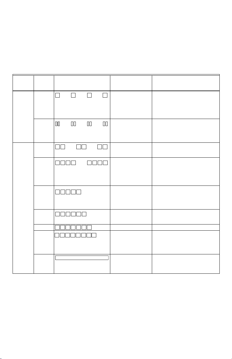
RÉGULATEURS DE CHAUFFE-EAU DE REMPLACEMENT WT8840
Numéro pièce de rechange Remplace Numéro FEO Remplacement FEO FEO
Réservoir, isolation de 1 po,
colonne d’eau de 4 po
Réservoir, isolation de 2 po,
colonne d’eau de 4 po
Réservoir, isolation de 1 po,
colonne d’eau de 5 po
Réservoir, isolation de 2 po,
colonne d’eau de 5 po
WV8840A1000 222-47463-01A
WV8840A1001 222-47463-01E Bradford White
WV8840A1050 222-47463-02A
WV8840A1051 222-47463-02E Bradford White
WV8840B1042 316910-000
WV8840B1109 316910-000 AOSmith
WV8840B1110 321166-000 AOSmith
WV8840B1059 316910-001
WV8840B1117 316910-001 AOSmith
WV8840B1118 321166-001 AOSmith
239-47463-01*
239-47463-02*
100112336 et
9007884005
100112337 et
9007885005
Bradford White
Bradford White
* Comprend la veilleuse et le joint de la chambre de combustion.
AOSmith
AOSmith
34-00013EF—03 2
 Loading...