

Page 1
Honeywell Proprietary
and Confidential REVISIONS
A
51121307
OneWireless Multinode
Agency Compliance
Professional Installation Guide
Honeywell Industrial Automation and Control
Ft. Washington, Pennsylvania
NOTICE – HONEYWELL INTERNATIONAL, INCORPORATED
TRADE SECRET - PROPRIETARY
Proprietary Notice:
This document and the information contained herein are confidential to, and the property of Honeywell, Inc. This
document and the information contained herein is made available only to employees of Honeywell, for the sole
purpose of conducting Honeywell's business. This document, and the information contained herein, shall be
maintained in strictest confidence; shall not be copied in whole or in part; and shall not be disclosed or distributed
to persons who are not employees of Honeywell, and for whom such information is not necessary in connection
with their assigned responsibilities. Upon request, or when the employee in possession of this document no longer
has need for this document for the authorized Honeywell purpose, this document shall be returned to the
employee's manager. There shall be no exceptions to the terms and conditions set forth herein except as
authorized in writing by the responsible Honeywell Vice President.
PRELIMINARY
FCF: OneWireless Multinode Agency Compliance
Professional Installation Guide
FMF: IACD/Ft.W
Made by: David Shipley
Issue: AT5 8/22/2007 SIZE Sh. No.: 1 of 31
Approval
Prints to
A 51121307
Honeywell
Page 2
Honeywell Proprietary
A
51121307
and Confidential REVISIONS
APPROVAL SIGNATURES
________________________________________________________________
Gary Brown, Hardware Engineering Manager Date
________________________________________________________________
John Herman, Program Management Date
__________________________________________________July 18, 2007__
Yu-Gene Chen, Product Marketing Date
________________________________________________________________
William Osei-Bonsu, Hardware Engineering Date
__________________________________________________July 18, 2007___
David Shipley, Agency Compliance Date
________________________________________________________________
Richard Allen, Agency Compliance Date
Revision Record
Revision
AT5 07/18/2007 Draft for Peer Review and signature sign off
Date
Purpose/Distribution
FCF: OneWireless Multinode Agency Compliance
Honeywell
Professional Installation Guide
FMF: IACD/Ft.W
Made by: David Shipley
Approval
Prints to
A 51121307
Issue: AT5 8/22/2007 SIZE Sh. No.: 2 of 31
Page 3

Honeywell Proprietary
A
51121307
and Confidential REVISIONS
TABLE OF CONTENTS
1 DESIGNATION, SCOPE AND PREFACE...........................................................................................6
1.1 DESIGNATION.....................................................................................................................................6
1.1.1 Model Numbers and Revisions :..................................................................................................6
1.2 SCOPE...............................................................................................................................................6
1.3 PREFACE ...........................................................................................................................................6
2 FEDERAL COMMUNICATION COMMISSION (FCC) ........................................................................7
2.1 FCC COMPLIANCE STATEMENT...........................................................................................................7
2.2 IMPORTANT FCC NOTE.................................................................................................................7
2.2.1 RF Safety Statement:...................................................................................................................7
2.3 FCC AND INDUSTRY CANADA (IC) IDENTIFICATION NUMBERS:..............................................................8
3 ABBREVIATIONS & DEFINITIONS ....................................................................................................9
4 MULTINODE GENERAL DESCRIPTION..........................................................................................10
4.1 INTENDED USE .................................................................................................................................10
4.2 MULTINODE DEVICE DIAGRAMS.........................................................................................................10
5 PRODUCT SPECIFICATIONS...........................................................................................................11
5.1 FREQUENCY HOPPING SPREAD SPECTRUM (FHSS) RADIO, 2.4GHZ..................................................11
5.2 IEEE 802.11A/B/G (WI-FI) RADIOS..................................................................................................12
5.3 MULTINODE USER ENVIRONMENT......................................................................................................13
5.4 MULTINODE POWER SPECIFICATIONS ................................................................................................13
5.5 WEIGHT ...........................................................................................................................................13
5.6 DIMENSIONS.....................................................................................................................................14
6 CABLES.............................................................................................................................................15
6.1 EXTERNAL INTERFACE CABLES..........................................................................................................15
6.2 ANTENNA CABLES.............................................................................................................................16
7 ANTENNA LIGHTNING ARRESTORS .............................................................................................16
7.1 FOR USE WITH INTEGRAL ANTENNA(S)...............................................................................................16
7.2 FOR USE WITH REMOTE ANTENNA(S).................................................................................................16
8 APPROVED ANTENNA TYPES/GAINS ...........................................................................................17
8.1 FHSS RADIO:..................................................................................................................................17
8.2 802.11A/B/G ACCESS POINT AND BRIDGE (MESH) RADIO ...................................................................17
9 EQUIVALENT ISOTROPICALLY RADIATED POWER (EIRP)........................................................18
10 EIRP LIMITS, FHSS RADIO ..............................................................................................................19
11 EIRP LIMITS, 802.11A (5.8GHZ) ACCESS POINT AND BRIDGE RADIO......................................20
12 EIRP LIMITS, 802.11A (5.4GHZ) ACCESS POINT AND BRIDGE RADIO......................................21
FCF: OneWireless Multinode Agency Compliance
Honeywell
Professional Installation Guide
FMF: IACD/Ft.W
Made by: David Shipley
Approval
Prints to
A 51121307
Issue: AT5 8/22/2007 SIZE Sh. No.: 3 of 31
Page 4

Honeywell Proprietary
A
51121307
and Confidential REVISIONS
13 EIRP LIMITS, 802.11B/G (2.4GHZ) ACCESS POINT AND BRIDGE RADIO..................................22
14 SETTING POWER AND COUNTRY CODE: FHSS RADIO..............................................................23
15 SETTING POWER & COUNTRY CODE: 802.11 ACCESS POINT & BRIDGE RADIO ..................24
15.1 POWER SETTING REFERENCE TABLE, 802.11 ACCESS POINT & BRIDGE RADIO:.................................26
16 AGENCY LABEL INFORMATION.....................................................................................................27
17 RF SAFETY, MAXIMUM PERMISSIBLE EXPOSURE (MPE) STATEMENT...................................28
18 AGENCY COMPLIANCE...................................................................................................................29
18.1 RADIO AND EMC CERTIFICATIONS ....................................................................................................29
18.1.1 Federal Communication Commission (FCC).........................................................................29
18.1.2 Industry Canada (IC).............................................................................................................29
18.1.3 European Telecommunications Standards Institue (ETSI)...................................................29
18.1.4 Australian communications and media authority (ACMA).....................................................29
18.2 PRODUCT SAFETY AGENCY CERTIFICATIONS .....................................................................................30
18.2.1 Canadian Standards Association (CSA)...............................................................................30
18.2.2 Factory Mutual (FM)..............................................................................................................30
18.2.3 European ATEX Certification (ATEX)....................................................................................31
18.3 EUROPEAN UNION CERTIFICATION (CE-MARK)...................................................................................31
19 REFERENCE DOCUMENTS.............................................................................................................31
FCF: OneWireless Multinode Agency Compliance
Honeywell
Professional Installation Guide
FMF: IACD/Ft.W
Made by: David Shipley
Approval
Prints to
A 51121307
Issue: AT5 8/22/2007 SIZE Sh. No.: 4 of 31
Page 5

Honeywell Proprietary
A
51121307
and Confidential REVISIONS
LIST OF FIGURES
Figure 1 –Diagram of Multinode Unit showing various external attributes ____________________________ 10
Figure 3 – Dimension of the Multinode Device_________________________________________________ 14
L
IST OF TABLES
Table 1 – Assembly Number and Revision........................................................................................................... 6
Table 2 –Table of Abbreviations and Definitions .................................................................................................. 9
Table 3 – Specifications of FHSS Radio in Multinode Device............................................................................ 11
Table 4 – IEEE 802.11a/b/g Wi-Fi Radio Specifications..................................................................................... 12
Table 5 – Specifications User Environment Multinode Device........................................................................... 13
Table 6 – Power Specifications Multinode Device.............................................................................................. 13
Table 7 – External Cable Specification for Multinode Device............................................................................. 15
Table 8 - Antenna Cable Specifications for Multinode Device............................................................................ 16
Table 9 – Lightning Arrestor Specifications for Integral Antenna(s) ................................................................... 16
Table 10 – Lightning Arrestor Specifications for Remote Antenna(s)................................................................. 16
Table 11 – Approved Antenna Types/Gains, FHSS Radio................................................................................. 17
Table 12 – Approved Antenna Types/Gains, 802.11a/b/g Radios .....................................................................17
Table 13 – EIRP Limits, FHSS Radio ................................................................................................................. 19
Table 14 – EIRP Limits, 802.11a (5.8GHz) Radios ............................................................................................ 20
Table 15 – EIRP Limits, 802.11a (5.4GHz) Radios ............................................................................................ 21
Table 16 – EIRP Limits, 802.11b/g (2.4GHz) Radios .........................................................................................22
Table 17 – Reference documents...................................................................................................................... 31
FCF: OneWireless Multinode Agency Compliance
Honeywell
Professional Installation Guide
FMF: IACD/Ft.W
Made by: David Shipley
Approval
Prints to
A 51121307
Issue: AT5 8/22/2007 SIZE Sh. No.: 5 of 31
Page 6
Honeywell Proprietary
A
51121307
and Confidential REVISIONS
1 DESIGNATION, SCOPE AND PREFACE
1.1 Designation
HONEYWELL ONEWIRELESS MULTINODE DEVICE.
1.1.1 Model Numbers and Revisions :
This document is valid for the following Multinode assembly number :
Number Revision Description
51153884-100 B
Honeywell OneWireless Multinode Device Top Level Assembly Drawing
Table 1 – Assembly Number and Revision
1.2 Scope
This document outlines professional installation requirements for the Honeywell Multinode
Device for the Honeywell OneWireless Network. Professional installation is required to
comply with certification agency and legal requirements. This document must be adhered to
for all installations of the Honeywell OneWireless Multinode device.
1.3 Preface
This manual covers professional installation of the optional external antennas for use with the
Honeywell OneWireless Multinode device. Since this device requires manual power limit
settings for use with the higher gain antennas, it is classified by the FCC as a professional
install device. To be in compliance with FCC requirements, the radio must be installed with
one of several approved antennas listed in this document. The Honeywell OneWireless
Multinode device works in conjunction with Honeywell XYR5000 and XYR6000 wireless
transmitters and Wi-Fi access point devices. See the Getting Started with Honeywell
OneWireless, Honeywell OneWireless Planning Guide and Honeywell OneWireless
Multinode User’s Guide, for general information on overall system implementation,
configuration, and management of the multimode.
FCF: OneWireless Multinode Agency Compliance
Honeywell
Professional Installation Guide
FMF: IACD/Ft.W
Made by: David Shipley
Approval
Prints to
A 51121307
Issue: AT5 8/22/2007 SIZE Sh. No.: 6 of 31
Page 7

Honeywell Proprietary
A
51121307
and Confidential REVISIONS
2 FEDERAL COMMUNICATION COMMISSION (FCC)
2.1 FCC Compliance Statement
This device complies with Part 15 of FCC Rules and Regulations. Operation is subject to the
following two conditions: (1) This device may not cause harmful interference and (2) this
device must accept any interference received, including interference that may cause
undesired operation. This equipment has been tested and found to comply with the limits for
a Class A digital device, pursuant to Part 15 of the FCC Rules. These limits are designed to
provide reasonable protection against harmful interference in a residential installation. This
equipment generates, uses, and can radiate radiofrequency energy and, if not installed and
used in accordance with these instructions, may cause harmful interference to radio
communications.
2.2 IMPORTANT FCC NOTE
Intentional or unintentional changes or modifications must not be made to the Multinode
unless under the express consent of the party responsible for compliance. Any such
modifications could void the user’s authority to operate the equipment and will void the
manufacturer’s warranty.
2.2.1 RF Safety Statement:
To comply with FCC’s and Industry Canada’s RF exposure requirements, the following
antenna installation and device operating configurations must be satisfied.
Remote Point-to-Multi-Point antenna(s) for this unit must be fixed and
mounted on outdoor permanent structures with a separation distance
between the antenna(s) of greater than 20cm and a separation distance of at
least 20cm from all persons.
Remote
Fixed Point–to-Point antenna(s) for this unit must be fixed and
mounted on outdoor permanent structures with a separation distance
between the antenna(s) of greater than 20cm and a separation distance of at
least 100cm from all persons.
Furthermore, when using integral antenna(s) the Multinode unit must not be
co-located with any other antenna or transmitter device and have a
separation distance of at least 20cm from all persons.
FCF: OneWireless Multinode Agency Compliance
Honeywell
Professional Installation Guide
FMF: IACD/Ft.W
Made by: David Shipley
Approval
Prints to
A 51121307
Issue: AT5 8/22/2007 SIZE Sh. No.: 7 of 31
Page 8

Honeywell Proprietary
A
51121307
and Confidential REVISIONS
2.3 FCC and Industry Canada (IC) Identification Numbers:
• Honeywell Multinode FHSS Radio Limited Modular Approval
o Federal Communication Commission Identification: S57 – WNMNFHSS
• Honeywell Multinode 802.11a/b/g Radio Limited Modular Approval
o Federal Communication Commission Identification: S57 – WNMNCM9
• Honeywell Multinode FHSS Radio Limited Modular Approval
o Industry Canada Identification: 573I – WNMNFHSS
• Honeywell Multinode 802.11a/b/g Radio Limited Modular Approval
o Industry Canada Identification: 573I – WNMNCM9
FCF: OneWireless Multinode Agency Compliance
Honeywell
Professional Installation Guide
FMF: IACD/Ft.W
Made by: David Shipley
Approval
Prints to
A 51121307
Issue: AT5 8/22/2007 SIZE Sh. No.: 8 of 31
Page 9

Honeywell Proprietary
A
51121307
and Confidential REVISIONS
3 Abbreviations & Definitions
The term Honeywell Multinode Device (or simply Multinode) will be used to describe the
composite unit which includes the Honeywell FHSS Radio Board, 3eTI Mesh Board, Power
Supply board, and all subassemblies housed inside the Multinode enclosure.
ACMA
ATEX
AWG
Co-located
COTS
CSA
EMC
ETSI
EU
FCC
FHSS
FM
IC
IEEE
IR
IrDA
LED
MPE
MTBF
NEMA
PCB
PCI
RAM
RJ-45
RPN
SQA
Wi-Fi
WNSIA
Australian Communications and Media Authority
Potentially Explosive Atmospheres Directive
American Wire Gauge
Two or more radios transmitting simultaneously and with less than
20cm of separation distance.
Commercial Off-The-Shelf
Canadian Standards Association
Electromagnetic Compatibility
European Telecommunications Standards Institute
European Union
Federal Communications Committee
Frequency-Hopping Spread Spectrum
Factory Mutual
Industry Canada
Institute of Electrical and Electronics Engineers
Infrared
Infrared Data Association
Light Emitting Diode
Maximum Permissible Exposure
Mean Time Between Failures
National Electrical Manufacturers Association
Printed Circuit Board
Peripheral Components Interconnect
Random Access Memory
Registered Jack-45
Reverse Polarity N-type
Supplier Quality Assurance
Wireless Local Area Network based on IEEE 802.11 Specifications
Wireless Network for Secure Industrial Application
Table 2 –Table of Abbreviations and Definitions
FCF: OneWireless Multinode Agency Compliance
Honeywell
Professional Installation Guide
FMF: IACD/Ft.W
Made by: David Shipley
Approval
Prints to
A 51121307
Issue: AT5 8/22/2007 SIZE Sh. No.: 9 of 31
Page 10
Honeywell Proprietary
A
51121307
and Confidential REVISIONS
4 MULTINODE GENERAL DESCRIPTION
4.1 Intended Use
The Multinode unit is a key component of the Honeywell Wireless Network for Secure
Industrial Application (WNSIA). It provides wireless mesh connectivity for wireless sensor
networks and wireless worker appliances. The Multinode uses powerful radios to
communicate with gateway devices connected to a wired DCS network, and a low-powered
radio to communicate with wireless sensors. The Multinode unit consists of two types of
radios: a sensor radio for communication with XYR 6000 transmitters and IEEE 802.11a/b/g
radios for mesh (bridge) network and communication with mobile access point (client)
devices.
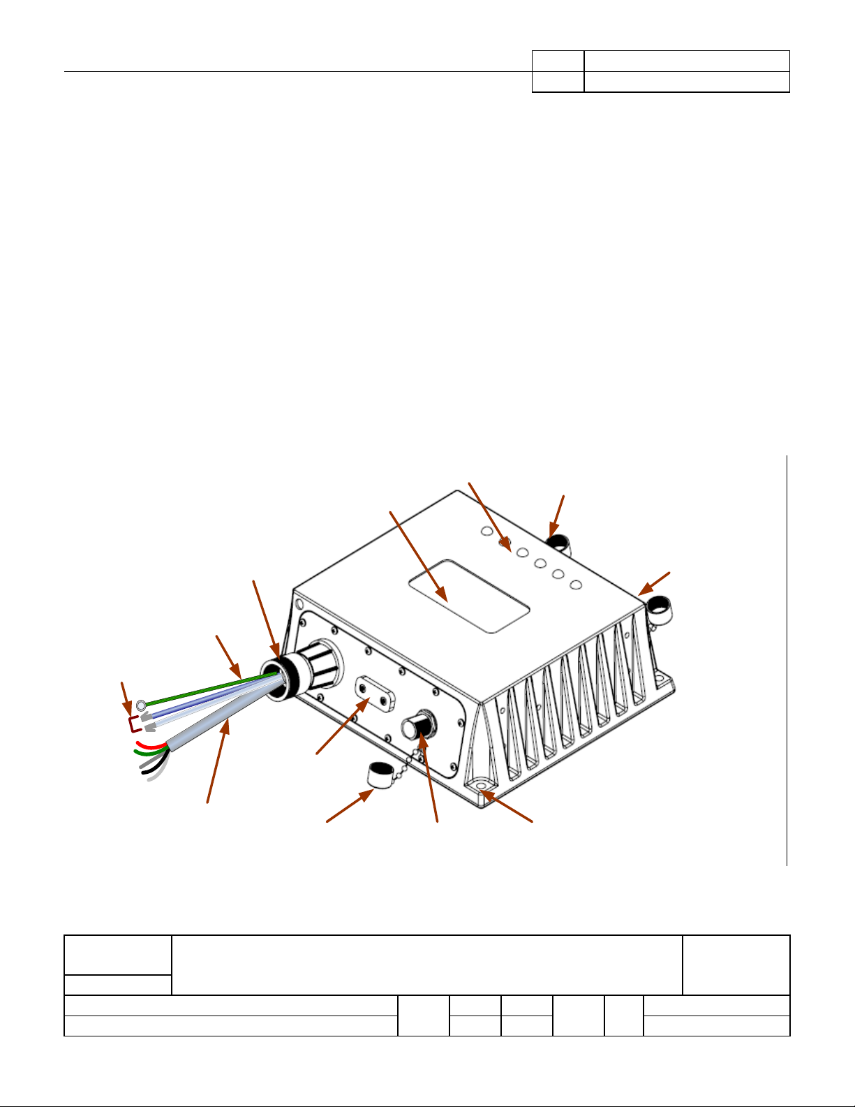
4.2 Multinode Device Diagrams
Figure 1 shows the unit-level drawing of the Multinode Device. All cables exit the unit via a ¾”
conduit hub. The conduit hub allows end user to land conduit on the Multinode Device.
1
shows the Multinode and all of external interfaces.
Figure
Client Ant C on.
Mesh Ant. Con.
(RPN-Type)
(Not Shown)
Honeywell Logo
Recess Area
LEDs (6X)
Ethernet
Cables
Mesh Ant Con.
Client Ant. Con.
(RPN-Type)
¾” Conduit Hub
Grou nd Cable
Infrared Port
24VDC P o we r
Cable
Figure 1 –Diagram of Multinode Unit showing various external attributes
Dust Boots
for Ant Con (3X)
FHSS Ant. Con.
(N-Type)
Mounting Holes (4X)
(Not Shown )
FCF: OneWireless Multinode Agency Compliance
Honeywell
Professional Installation Guide
FMF: IACD/Ft.W
Made by: David Shipley
Approval
Prints to
A 51121307
Issue: AT5 8/22/2007 SIZE Sh. No.: 10 of 31
Page 11

Honeywell Proprietary
A
51121307
and Confidential REVISIONS
5 PRODUCT SPECIFICATIONS
5.1 Frequency Hopping Spread Spectrum (FHSS) Radio, 2.4GHz
Warning! The Multinode unit must be Professionally Installed in accordance with the
requirements specified in this document. See Section 10, for professional installation
maximum power setting requirements. Only the specified power settings, antenna types and
gains and cable lengths (attenuation) as outlined in this document are valid for Multinode
installations.
Item Specification
Wireless Standard
Data Rates and Modulation Data Rate: 250kbps
Frequency Band 2,402 – 2,482MHz
Transmit Power
Receive Sensitivity
(typical)
Frequency Hopping Spread Spectrum (FHSS), 2.4GHz
Modulation: Gaussian Frequency Shift Keying (GFSK)
Maximum: 19dBm
(Maximum transmit power will vary by channel and individual country
regulations.
-98dBm
Table 3 – Specifications of FHSS Radio in Multinode Device.
FCF: OneWireless Multinode Agency Compliance
Honeywell
Professional Installation Guide
FMF: IACD/Ft.W
Made by: David Shipley
Approval
Prints to
A 51121307
Issue: AT5 8/22/2007 SIZE Sh. No.: 11 of 31
Page 12

Honeywell Proprietary
A
51121307
and Confidential REVISIONS
5.2 IEEE 802.11a/b/G (Wi-Fi) Radios
The Multinode has two IEEE 802.11 radios for implementing client (access point) and mesh
(bridge) networks.
Warning! The Multinode unit must be Professionally Installed in accordance with the
requirements specified in this document. See Section 11, for professional installation
maximum power setting requirements. Only the specified power settings, antenna types and
gains and cable lengths (attenuation) as outlined in this document are valid for Multinode
installations.
Item Specification
Wireless Standards
Data Rates and
Modulation
Frequency Bands and
Operating Channels
Transmit power
(Maximum transmit
power will vary by
channel, data rate, and
individual country
regulations.
Receive sensitivity
(typical)
IEEE 802.11a/b/g
• 802.11a: 54, 48, 36, 24, 18, 12, 9, 6 Mbps, Orthogonal Frequency Division
Multiplexing (OFDM)
• 802.11b: 11, 5.5, 2, 1 Mbps, Direct Sequence Spread Spectrum (DSSS)
• 802.11g: 54, 48, 36, 24, 18, 12, 9, 6 Mbps, OFDM
United States and Canada (FCC and IC):
• 802.11b/g: 2,412 – 2,462MHz, Channels 1 – 11
• 802.11a: 5,745 – 5,825, Channels 149,153,157,161,165
Europe (ETSI):
• 802.11b/g: 2,412 – 2,472MHz, Channels 1 – 13
• 802.11a: 5,500 – 5,700, Channels
100,104,108,112,116,120,124,128,132,136,140
Australia (ACMA):
• 802.11b/g: 2,412 – 2,472MHz, Channels 1 – 13
• 802.11a: 5,745 – 5,825, Channels 149,153,157,161,165
Maximum:
• 802.11a: 23 dBm
• 802.11b: 16 dBm
• 802.11g: 16 dBm
802.11a:
-88dB@6Mbps, -87dB@9Mbps, -85@12Mbps, -83dB@18Mbps,
-80dB@24Mbps, -75dB@36Mbps, -73dB@48Mbps, -71dB@54Mbps
802.11b:
-95dB@1Mbps, -94dB@2Mbps, -92dB@5.5Mbps, -90dB@11Mbps
802.11g:
-90dB@6Mbps, -89dB@9Mbps, -87@12Mbps, -85dB@18Mbps,
-82dB@24Mbps, -79dB@36Mbps, -76dB@48Mbps, -74dB@54Mbps
Table 4 – IEEE 802.11a/b/g Wi-Fi Radio Specifications.
FCF: OneWireless Multinode Agency Compliance
Honeywell
Professional Installation Guide
FMF: IACD/Ft.W
Made by: David Shipley
Approval
Prints to
A 51121307
Issue: AT5 8/22/2007 SIZE Sh. No.: 12 of 31
Page 13

Honeywell Proprietary
A
51121307
and Confidential REVISIONS
5.3 Multinode User Environment
Item Specification
Operating Temperature: -20 OC to +60 OC
Storage Temperature: -20 OC to +60 OC
Operating Humidity: 0 to 100% RH
Table 5 – Specifications User Environment Multinode Device.
5.4 Multinode Power Specifications
Item Specification
Operating Voltage: 20.4Vdc to 26.4Vdc
Power Consumption
(typical):
25W
Table 6 – Power Specifications Multinode Device.
5.5 Weight
The weight of the complete Multinode units shall be 7.0 lb. (3.2 kg) maximum. This weight
does not include the integral antennas.
.
FCF: OneWireless Multinode Agency Compliance
Honeywell
Professional Installation Guide
FMF: IACD/Ft.W
Made by: David Shipley
Approval
Prints to
A 51121307
Issue: AT5 8/22/2007 SIZE Sh. No.: 13 of 31
Page 14

Honeywell Proprietary
A
51121307
and Confidential REVISIONS
5.6 Dimensions
Figure 2 – Dimension of the Multinode Device
FCF: OneWireless Multinode Agency Compliance
Honeywell
Professional Installation Guide
FMF: IACD/Ft.W
Made by: David Shipley
Approval
Prints to
A 51121307
Issue: AT5 8/22/2007 SIZE Sh. No.: 14 of 31
Page 15

Honeywell Proprietary
A
51121307
and Confidential AT1 REVISIONS
6 Cables
6.1 External Interface Cables
Cable Type Specification Qty Comments/Specification
External
Ethernet
CAT5E
Stranded Core
2 Routed through conduit hub.
Termination = RJ-45 Modular Plug
Finished Length = 24 inches
24VDC Power Multi-
conductor,
AWG
1 Finished Length = 24 inches
Routed through conduit hub
Conductor Color:
Red & Black = 24VDC
White & Green = Common
Drain wire = Chassis potential
Ground
Conductor
AWG10 1 Routed through conduit hub
Color = Green or Green with yellow stripes.
Finished length = 24 inches
Note:
• Finished length is measured from conduit hub to outside tip of cable.
• Ground conductor must be attached to product safety protective earth and building steel ground.
• All external wiring must be routed through metal conduit.
Table 7 – External Cable Specification for Multinode Device.
FCF: OneWireless Multinode Agency Compliance
Honeywell
Professional Installation Guide
FMF: IACD/Ft.W
Made by: David Shipley
Approval
Prints to
A 51121307
Issue: AT1 08/01/2007 SIZE Sh. No.: 15 of 31
Page 16

Honeywell Proprietary
A
51121307
and Confidential AT1 REVISIONS
6.2 Antenna Cables
Cable
Application
FHSS 50018278FHSS 50018278FHSS 50018278-
802.11a/b/g 51202358-
802.11a/b/g 51202358-
802.11a/b/g 51202358-
Honeywell
Part #
001
003
010
001
003
010
Cable
Type
400
Series
400
Series
400
Series
400
Series
400
Series
400
Series
Connector
Type
Frequency
(GHz)
Length
(m)
N male to N male 2.4 1 0.9
N male to N male 2.4 3 1.1
N male to N male 2.4 10 2.4
RPN plug to N
2.4/5.8 1 0.9 / 1.8
male
RPN plug to N
2.4/5.8 3 1.1 / 2.3
male
RPN plug to N
2.4/5.8 10 2.4 / 3.8
male
Table 8 - Antenna Cable Specifications for Multinode Device.
Loss
(dB)
7 Antenna Lightning Arrestors
7.1 For use with Integral Antenna(s)
Application Honeywell
Part Number
Specification Connector
Type
Frequency
(GHz)
Attenuation
(dB)
FHSS 51202359-200 50 ohm NM - NF 0 – 6 0.4 (max)
802.11 a/b/g 51202359-300 50 ohm RPN Plug -
0 - 6 0.5 (max)
NF
Table 9 – Lightning Arrestor Specifications for Integral Antenna(s)
7.2 For use with Remote Antenna(s)
Application Honeywell
Part Number
Specification Connector
Type
Frequency
(GHz)
Attenuation
(dB)
FHSS 50018279-090 50 ohm NF to NF 0 – 3 0.4 (max)
802.11 a/b/g 51202359-100 50 ohm NF toNF 0 - 6 0.5 (max)
NOTE: Depending on application needs, the “integral” arrestors may be used for remote antennas.
Table 10 – Lightning Arrestor Specifications for Remote Antenna(s)
FCF: OneWireless Multinode Agency Compliance
Honeywell
Professional Installation Guide
FMF: IACD/Ft.W
Made by: David Shipley
Approval
Prints to
A 51121307
Issue: AT1 08/01/2007 SIZE Sh. No.: 16 of 31
Page 17

Honeywell Proprietary
A
51121307
and Confidential AT1 REVISIONS
8 Approved Antenna Types/Gains
8.1 FHSS Radio:
Antenna
Type
Omni
(integral)
Omni
(remote)
Sector
(remote)
Antenna
Application
Point to
Multi-Point
Point to
Multi-Point
Point to
Multi-Point
Manufacturer Manufacturer
Part Number
SMARTANT
HON04-
052160
HYPERLINK HGV-2409U
HYPERLINK
HG2414SP-
120
Honeywell
Part
Number
51506534-
100
50018414-
001
Beam
Width
Omni 5 2.4
Omni 8 2.4
NA 120° 14 2.4
Peak
Gain
(dBi)
Freq.
(GHz
)
Agency
Compliance
FCC, IC,
ETSI, ACMA
FCC, IC,
ETSI, ACMA
FCC, IC,
ETSI, ACMA
Table 11 – Approved Antenna Types/Gains, FHSS Radio
8.2 802.11a/b/g Access point and Bridge (Mesh) Radio
Antenna
Type
Omni
(integral)
Omni
(remote)
Omni
(remote)
Omni
(remote)
Sector
(remote)
Sector
(remote)
Sector
(remote)
YAGI
(remote)
DISH
(remote)
DISH
(remote)
Antenna
Application
Point to
Multi-Point
Point to
Multi-Point
Point to
Multi-Point
Point to
Multi-Point
Point to
Multi-Point
Point to
Multi-Point
Point to
Multi-Point
Point to
Multi-Point
Fixed Point
to Point
Fixed Point
to Point
Manufacturer
SMARTANT SAA04-220080
HYPERLINK HGV-2409U
HYPERLINK HG5412U NA Omni 12
HYPERLINK HG5812U-PRO NA Omni 12
HYPERLINK HG2414SP-120 NA 120° 14
HYPERLINK HG5417P-090 NA 90° 17
HYPERLINK HG5817P-090 NA 90° 17
TELEX 5816AB NA 19° 16.5
HYPERLINK HG5423D NA 9° 23
HYPERLINK HG5824D NA 9° 24
Manufacturer
Part Number
Honeywell
Part
Number
51153883-
305
50018414-
001
Beam
Width
Omni
Omni 8
Peak
Gain
(dBi)
4.5
7
Freq
(GHz)
2.4
802.11b/g
5.4
802.11a
5.8
802.11a
2.4
802.11b/g
5.4
802.11a
5.8
802.11a
2.4
802.11b/g
5.4
802.11a
5.8
802.11a
5.8
802.11a
5.4
802.11a
5.8
802.11a
Agency
Compliance
FCC, IC,
ETSI, ACMA
FCC, IC,
FCC, IC,
ETSI, ACMA
FCC, IC,
FCC, IC,
ETSI, ACMA
FCC, IC,
FCC, IC,
FCC, IC,
ETSI
ACMA
ETSI
ACMA
ETSI
ACMA
ACMA
ETSI
ACMA
Table 12 – Approved Antenna Types/Gains, 802.11a/b/g Radios
FCF: OneWireless Multinode Agency Compliance
Honeywell
Professional Installation Guide
FMF: IACD/Ft.W
Made by: David Shipley
Approval
Prints to
A 51121307
Issue: AT1 08/01/2007 SIZE Sh. No.: 17 of 31
Page 18

Honeywell Proprietary
A
51121307
and Confidential AT1 REVISIONS
9 Equivalent Isotropically Radiated Power (EIRP)
In radio communication systems, Equivalent isotropically radiated power (EIRP), or
alternatively, Effective isotropic radiated power is the amount of power that would have to be
emitted by an isotropic antenna (that evenly distributes power in all directions and is a
theoretical construct) to produce the peak power density observed in the direction of
maximum antenna gain. EIRP can take into account the losses in transmission line and
connectors and includes the gain of the antenna. The EIRP is often stated in terms of
decibels over a reference power level, that would be the power emitted by an isotropic
radiator with an equivalent signal strength. The EIRP allows making comparisons between
different emitters regardless of type, size or form. From the EIRP, and with knowledge of a
real antenna's gain, it is possible to calculate real power and field strength values.
EIRP(dBm) = (Radio Power (dBm)) – (Cable Loss (dB)) + (Antenna Gain(dBi))
Antenna gain is expressed relative to a (theoretical) isotropic reference antenna (dBi).
FCF: OneWireless Multinode Agency Compliance
Honeywell
Professional Installation Guide
FMF: IACD/Ft.W
Made by: David Shipley
Approval
Prints to
A 51121307
Issue: AT1 08/01/2007 SIZE Sh. No.: 18 of 31
Page 19

Honeywell Proprietary
A
51121307
and Confidential AT1 REVISIONS
10 EIRP LIMITS, FHSS RADIO
Antenna
Type
Omni
Omni
Sector
Radio Usage /
Application
Point to
Multi-
Point
Point to
Multi-
Point
Point to
Multi-
Point
Max.
Freq.
(GHz)
Integral 2.4 5 0 0
Remote 2.4 8 1 0.9
Remote 2.4 14 1 0.9
Ant.
Gain
(dBi)
Min. Cable
Length
(m)
Min.
Cable
Loss
(dB)
Max. Radio
Output
Power (dBm)
Max.
EIRP
(dBm)
19 24
14 19
17 24
12 19
12 25
6 19
Agency/
Country
FCC, IC
ETSI, ACMA
FCC, IC
ETSI, ACMA
FCC, IC
ETSI, ACMA
Notes:
1. The values in the above table have been determined through agency certification testing.
2. The following shall apply for antenna type, frequency range, application/usage and agency/country
compliance:
• Antenna gains above the maximum values shown shall not be used.
• Cable length/loss below the minimum values shown shall not be used.
• Maximum overall radio output power shown shall not be exceeded.
• Maximum EIRP values shown above shall not be exceeded.
Table 13 – EIRP Limits, FHSS Radio
FCF: OneWireless Multinode Agency Compliance
Honeywell
Professional Installation Guide
FMF: IACD/Ft.W
Made by: David Shipley
Approval
Prints to
A 51121307
Issue: AT1 08/01/2007 SIZE Sh. No.: 19 of 31
Page 20

Honeywell Proprietary
A
51121307
and Confidential AT1 REVISIONS
11 EIRP LIMITS, 802.11a (5.8GHz) Access Point and Bridge Radio
Max.
Radio
Output
Power
(dBm)
Max.
EIRP
(dBm)
Pro-
Install
Power
Setting
23 30 25
23 30 25
23 33 25
20 30 2
17 32 -7
14 30 -12
17 31 -7
15 30 -11
23 45 25
8 30 -24
Agency/
Country
FCC, IC
FCC, IC
FCC, IC
FCC, IC
FCC, IC
Ant.
Type
Omni
Omni
Sector
Yagi
Dish
Radio Usage /
Application
Point to
Multi-Point
Point to
Multi-Point
Point to
Multi-Point
Point to
Multi-Point
Fixed
Pt. to Pt.
Integral
Remote
Remote
Remote
Remote
Freq.
(GHz)
5.8
802.11a
5.8
802.11a
5.8
802.11a
5.8
802.11a
5.8
802.11a
Max.
Ant.
Gain
(dBi)
7 0 0
12 1 1.8
17 1 1.8
16.5 1 1.8
24 1 1.8
Min.
Cable
Length
(m)
Min.
Cable
Loss
(dB)
Notes:
1. The values in the above table have been determined through agency certification testing.
2. Maximum transmit power will vary by channel, data rate, and individual country regulations.
3. The following shall apply for antenna type, frequency range, application/usage and agency/country
compliance:
• Antenna gains above the maximum values shown shall not be used.
• Cable length/loss below the minimum values shown shall not be used.
• Maximum overall radio output power shown shall not be exceeded.
• Maximum EIRP values shown above shall not be exceeded.
ACMA
ACMA
ACMA
ACMA
ACMA
Table 14 – EIRP Limits, 802.11a (5.8GHz) Radios
FCF: OneWireless Multinode Agency Compliance
Honeywell
Professional Installation Guide
FMF: IACD/Ft.W
Made by: David Shipley
Approval
Prints to
A 51121307
Issue: AT1 08/01/2007 SIZE Sh. No.: 20 of 31
Page 21

Honeywell Proprietary
A
51121307
and Confidential AT1 REVISIONS
12 EIRP LIMITS, 802.11a (5.4GHz) Access Point and Bridge Radio
Max.
Radio
Output
Power
(dBm)
Max.
EIRP
(dBm)
Pro-
Install
Power
Setting
23 30 2
19 30 -6
14 30 -17
8 30 -35
Agency/
Country
Ant.
Type
Omni
Omni
Sector
Dish
Radio Usage /
Application
Point to
Multi-Point
Point to
Multi-Point
Point to
Multi-Point
Fixed
Pt. to Pt.
Integral
Remote
Remote
Remote
Freq.
(GHz)
5.4
802.11a
5.4
802.11a
5.4
802.11a
5.4
802.11a
Max.
Ant.
Gain
(dBi)
7 0 0
12 1 1.8
17 1 1.8
23 1 1.8
Min.
Cable
Length
(m)
Min.
Cable
Loss
(dB)
Notes:
1. The values in the above table have been determined through agency certification testing.
2. Maximum transmit power will vary by channel, data rate, and individual country regulations.
3. The following shall apply for antenna type, frequency range, application/usage and agency/country
compliance:
• Antenna gains above the maximum values shown shall not be used.
• Cable length/loss below the minimum values shown shall not be used.
• Maximum overall radio output power shown shall not be exceeded.
• Maximum EIRP values shown above shall not be exceeded.
ETSI
ETSI
ETSI
ETSI
Table 15 – EIRP Limits, 802.11a (5.4GHz) Radios
FCF: OneWireless Multinode Agency Compliance
Honeywell
Professional Installation Guide
FMF: IACD/Ft.W
Made by: David Shipley
Approval
Prints to
A 51121307
Issue: AT1 08/01/2007 SIZE Sh. No.: 21 of 31
Page 22

Honeywell Proprietary
A
51121307
and Confidential AT1 REVISIONS
13 EIRP LIMITS, 802.11b/g (2.4GHz) Access Point and Bridge Radio
Max.
Radio
Output
Power
(dBm)
Max.
EIRP
(dBm)
Pro-
Install
Power
Setting
16 21 40
15 19 2
16 23 40
12 19 -4
16 28 40
6 19 -23
Agency/
Country
FCC, IC
ETSI, ACMA
FCC, IC
ETSI, ACMA
FCC, IC
ETSI, ACMA
Ant.
Type
Omni
Omni
Sector
Radio Usage /
Application
Point to
Multi-Point
Point to
Multi-Point
Point to
Multi-Point
Integral
Remote
Remote
Freq.
(GHz)
2.4
802.11b/g
2.4
802.11b/g
2.4
802.11b/g
Max.
Ant.
Gain
(dBi)
4.5 0 0
8 1 0.9
14
Min.
Cable
Length
(m)
10 2.4
1 0.9
Min.
Cable
Loss
(dB)
Notes:
1. The values in the above table have been determined through agency certification testing.
2. Maximum transmit power will vary by channel, data rate, and individual country regulations.
3. The following shall apply for antenna type, frequency range, application/usage and agency/country
compliance:
• Antenna gains above the maximum values shown shall not be used.
• Cable length/loss below the minimum values shown shall not be used.
• Maximum overall radio output power shown shall not be exceeded.
• Maximum EIRP values shown above shall not be exceeded.
Table 16 – EIRP Limits, 802.11b/g (2.4GHz) Radios
FCF: OneWireless Multinode Agency Compliance
Honeywell
Professional Installation Guide
FMF: IACD/Ft.W
Made by: David Shipley
Approval
Prints to
A 51121307
Issue: AT1 08/01/2007 SIZE Sh. No.: 22 of 31
Page 23

Honeywell Proprietary
A
51121307
and Confidential AT1 REVISIONS
14 Setting Power and Country Code: FHSS Radio
Warning! The Multinode unit must be Professionally Installed in accordance with the
requirements specified in this document. Only the specified power settings, antenna types
and gains and cable lengths (attenuation) as outlined in this document are valid for Multinode
installations.
Set the radio power level using the Authentication Device application. Due to regulations, this
command is only available if professional installer options have explicitly been enabled on
your PDA. If you have not enabled professional installer options and would like to do so,
please contact Honeywell DE or TAC. A separate application, AuthDev Power Settings, is
required to enable the "Write TX Power Level" option.
Perform the following procedure to read and change the radio power level on your multinode
or wireless device:
• Open the Authentication Device application on your Windows Mobile PDA.
• From the main menu, choose the Advanced Options menu to open the Advanced
Options form.
• From the Advanced Options form, choose "Read TX Power Level" from the command
drop down box.
• Aim the Authentication Device at your node and press the Transmit Command button
to read the data from the node. The TX Power reading will be presented on your
screen.
• If you have enabled professional installer options within the Authentication Device,
choose the "Write TX Power Level" from the command drop down box.
• Choose a new power level. Aim the Authentication Device at your node and press the
Transmit Command button to write the data to the node.
FCF: OneWireless Multinode Agency Compliance
Honeywell
Professional Installation Guide
FMF: IACD/Ft.W
Made by: David Shipley
Approval
Prints to
A 51121307
Issue: AT1 08/01/2007 SIZE Sh. No.: 23 of 31
Page 24

Honeywell Proprietary
A
51121307
and Confidential AT1 REVISIONS
15 Setting Power & Country Code: 802.11 Access Point & Bridge Radio
Warning! The Multinode unit must be Professionally Installed in accordance with the
requirements specified in this document. Only the specified power settings, antenna types
and gains and cable lengths (attenuation) as outlined in this document are valid for Multinode
installations.
Programming the Country Code
A hidden page on the Multinode Configuration Tool has been designed for professional
installers to change country code and radio output power settings. A valid authorization code
has to be entered for the any information to be modified. This authorization code is hard-
coded in the firmware and shall be kept as a SECRET at all times.
To access the hidden page, type the following URL in your browser:
https://192.168.254.128/cgi-bin/sgateway?PG=911
Change 192.168.254.128 to the IP address of your unit, and make sure you login as:
Login: CryptoOfficer, Password: CryptoFIPS
You should see something like this:
FCF: OneWireless Multinode Agency Compliance
Honeywell
Professional Installation Guide
FMF: IACD/Ft.W
Made by: David Shipley
Approval
Prints to
A 51121307
Issue: AT1 08/01/2007 SIZE Sh. No.: 24 of 31
Page 25

Honeywell Proprietary
A
51121307
and Confidential AT1 REVISIONS
The authorization code is: “Raptor2007!” without the quote (YOU MUST KEEP THIS AS A
SECRET)
Change the following options based on values you determined in Section 11:
Country Code
Adjustment to Max TX power of Access Point Radio (increase or decrease)
Adjustment to Max TX power of Bridge Radio (increase or decrease)
After applying the changes, you will be notified to reboot the unit for any changes to take
effect.
Note that the adjustment of radio Max TX power has limits. It will level off on both the low end
and high end. This feature is provided for professional installers to adjust the card output
power to match the specific selection of antenna and keep the total output power under the
regulatory threshold.
The setting here are saved in non-volatile memory inside the unit. Restoring the unit to
factory default settings does not change these values.
FCF: OneWireless Multinode Agency Compliance
Honeywell
Professional Installation Guide
FMF: IACD/Ft.W
Made by: David Shipley
Approval
Prints to
A 51121307
Issue: AT1 08/01/2007 SIZE Sh. No.: 25 of 31
Page 26

Honeywell Proprietary
A
51121307
and Confidential AT1 REVISIONS
15.1 Power Setting Reference Table, 802.11 Access Point & Bridge Radio:
Multinode Bridge and Access Point Radio Ports
WIRELESS MODE 802.11a 802.11a 802.11b/g mixed 802.11b/g mixed
CHANNEL 120 (5.6GHz) 157 (5.785GHz) 7 (2.442GHz) 6 (2.437GHz)
TX PWR MODE FIXED, 8 FIXED, 8 FIXED, 8 FIXED, 8
Professional
Installer TX Power
Setting
40 24.0 23.0 17.2 16.2
35 24.0 23.0 17.2 16.2
30 24.0 23.0 17.2 16.2
25 24.0 23.0 17.2 16.2
20 24.0 23.0 17.2 16.2
15 24.0 23.0 17.2 16.2
10 23.9 20.7 17.2 16.2
5
0
-5
-10
-15
-20
-25
-30
-35
-40
MEASURED
OUTPUT POWER
(dBm)
23.7
21.8
19.7
17.0
15.0
12.5
9.7
8.5
8.4
8.4
MEASURED
OUTPUT POWER
(dBm)
20.1 15.7 16.2
19.6 13.8 16.1
17.2 11.3 12.4
15.7 9.0 10.7
11.8 7.4 8.4
8.9 6.7 6.4
7.3 5.2 4.9
5.2 2.4 2.8
4.6 2.3 1.6
4.6 2.3 1.4
MEASURED
OUTPUT POWER
(dBm)
MEASURED
OUTPUT POWER
(dBm)
FCF: OneWireless Multinode Agency Compliance
Honeywell
Professional Installation Guide
FMF: IACD/Ft.W
Made by: David Shipley
Approval
Prints to
A 51121307
Issue: AT1 08/01/2007 SIZE Sh. No.: 26 of 31
Page 27

Honeywell Proprietary
A
51121307
and Confidential AT1 REVISIONS
16 Agency Label Information
The following information shall be clearly and permanently labeled on the Multinode unit:
FCF: OneWireless Multinode Agency Compliance
Honeywell
Professional Installation Guide
FMF: IACD/Ft.W
Made by: David Shipley
Approval
Prints to
A 51121307
Issue: AT1 08/01/2007 SIZE Sh. No.: 27 of 31
Page 28

Honeywell Proprietary
A
51121307
and Confidential AT1 REVISIONS
17 RF Safety, Maximum Permissible Exposure (MPE) statement
To comply with FCC’s and Industry Canada’s RF exposure requirements, the following
antenna installation and device operating configurations must be satisfied.
Remote Point-to-Multi-Point antenna(s) for this unit must be fixed and mounted
on outdoor permanent structures with a separation distance between the
antenna(s) of greater than 20cm and a separation distance of at least
persons.
Remote Fixed Point–to-Point antenna(s) for this unit must be fixed and mounted
on outdoor permanent structures with a separation distance between the
antenna(s) of greater than 20cm and a separation distance of at least
all persons.
Furthermore, when using integral antenna(s) the Multinode unit must not be co-
located with any other antenna or transmitter device and have a separation
distance of at least 20cm from all persons.
20cm from all
100cm from
FCF: OneWireless Multinode Agency Compliance
Honeywell
Professional Installation Guide
FMF: IACD/Ft.W
Made by: David Shipley
Approval
Prints to
A 51121307
Issue: AT1 08/01/2007 SIZE Sh. No.: 28 of 31
Page 29

Honeywell Proprietary
A
51121307
and Confidential AT1 REVISIONS
18 AGENCY COMPLIANCE
18.1 Radio and EMC Certifications
18.1.1 Federal Communication Commission (FCC)
Specification: FCC Part 15.247 Subpart B for unintentional radiators
Specification: FCC Part 15.247 Subpart C for intentional radiators
18.1.2 Industry Canada (IC)
Specification: FCC Part 15.247 Subpart B for unintentional radiators
Specification: FCC Part 15.247 Subpart C for intentional radiators
Method: RSS-210, Issue 6 and RSS-Gen, Issue 1
18.1.3 European Telecommunications Standards Institue (ETSI)
Emissions Specification and Method: EN 300 328 V1.7.1
Emissions Spec and Method: EN 301 893 V1.3.1
Immunity Specification: EN 301 489-17 V1.2.1
Immunity Method: EN 301 489-1 V1.6.1
Product Standard: IEC61326-1 (1st Edition, 2002-02, Industrial Locations)
18.1.4 Australian communications and media authority (ACMA)
Specification: AS NZS 4771-2000
FCF: OneWireless Multinode Agency Compliance
Honeywell
Professional Installation Guide
FMF: IACD/Ft.W
Made by: David Shipley
Approval
Prints to
A 51121307
Issue: AT1 08/01/2007 SIZE Sh. No.: 29 of 31
Page 30

Honeywell Proprietary
A
51121307
and Confidential AT1 REVISIONS
18.2 Product Safety Agency Certifications
18.2.1 Canadian Standards Association (CSA)
IEC61010-1 (2nd Edition, 2001-02), "Safety Requirements for Electrical Equipment for
Measurement, Control and Laboratory Use, part 1: General Requirements
CSA HAZ-LOC Standards?
• Temperature code: T4 (135°C) based on the maximum specified ambient of 60°C.
18.2.2 Factory Mutual (FM)
FM electrical equipment requirements for use within Class I, Division 2, Groups A, B, C and
D/Zone 2, Group IIC Hazardous Locations.
Factory Mutual Approval Standard Class No. 3600, "Electrical Equipment for Use in
Hazardous (Classified) Locations - General Requirements
Factory Mutual Approval Standard Class No. 3810, "Electrical and Electronic Test,
Measuring, and Process Control Equipment
Factory Mutual Approval Standard Class No. 3611, "Electrical Equipment for Use in Class I,
Division 2, Class II, Division 2 and Class III, Division 1 and 2 Hazardous (Classified)
Locations
• Temperature code: T4 (135°C) based on the maximum specified ambient of 60°C.
FCF: OneWireless Multinode Agency Compliance
Honeywell
Professional Installation Guide
FMF: IACD/Ft.W
Made by: David Shipley
Approval
Prints to
A 51121307
Issue: AT1 08/01/2007 SIZE Sh. No.: 30 of 31
Page 31

Honeywell Proprietary
A
51121307
and Confidential AT1 REVISIONS
18.2.3 European ATEX Certification (ATEX)
The completely assembled Multinode will conform to European electrical equipment
requirements for use within Zone 2, Ex n IIC, Hazardous Locations.
European Norms Standard EN 50014:1992, "Electrical Apparatus for Potentially Explosive
Atmospheres - General Requirements"
European Norms Standard EN 50021:1999, "Electrical Apparatus for Potentially Explosive
Atmospheres - Type of Protection "n"
The temperature code for the Multinode shall not exceed T4 (135°C) based on the maximum
specified ambient of 60°C.
18.3 European Union Certification (CE-mark)
• Compliance with:
o R&TTE Directive 1999/5/EC
o EMC Directive 2004/108/EC
o LVD Directive 73/23/EEC
o ATEX Directive 94/9/EC
19 Reference Documents
1
Getting Started with Honeywell OneWireless
2
Honeywell OneWireless Planning Guide
3
Honeywell OneWireless Multinode User’s Guide
4
Radio Antenna: A Primer White Paper
5
Honeywell OneWireless System Administration Guide
6
Honeywell OneWireless Field Network Dictionary
7
OneWireless Builder Parameter Reference
8
OneWireless Builder User’s Guide
Table 17 – Reference documents
FCF: OneWireless Multinode Agency Compliance
Honeywell
Professional Installation Guide
FMF: IACD/Ft.W
Made by: David Shipley
Approval
Prints to
A 51121307
Issue: AT1 08/01/2007 SIZE Sh. No.: 31 of 31
 Loading...