How it Works
Log In / Sign Up
Buy Points
How it Works
FAQ
Contact Us
Questions and Suggestions
Users
Honeywell
Loading...
W
w964f
WA510
Wafer Flanged Dynamic Pressure-regulated Control Valves
WAP
WAP-PLUS
WAVE2EX
WBR-AK
WBX
WCPU66LB
WD4SE
WEB-600
WEB-600-O
WEB-600-O-US
WEB-600-US
WEB-645
WEB-700
2
WEB-700-O
2
WEB/CP-202-XPR
WEB/CP-202-XPR-GW
WEB/CP-602-XPR
WEB/CP-602-XPR-GW
WEB-RL6N
WEB-RS5N
WebStat
WebStatô
WFSADPT
WFSAV
WFSGW
WFSLCDUI
WFSMM
WFSPS
WFSRM
WFSSD
WFSSM
WG510
WI0U100A
WI0U100B
WI0U66LA
WiFi Thermostat
Wi-Fi Thermostat 9000
Wi-Fi VisionPRO 8000
3
Win-Pak PE
Win-Pak Pro International
Win-Pak SE
Wireless
2
Wireless Alarm Bar
Wireless Dual Discrete Input Transmitter
Wireless FocusPRO 5000
Wireless FocusPRO 6000
Wireless Occupancy Solution
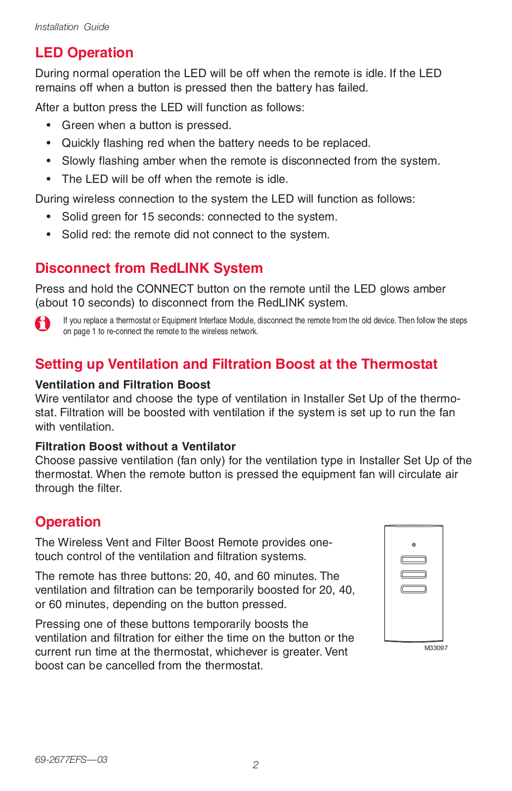
Wireless Vent and Filter Boost Remote
Wireless Vent Boost Remote
Wireless Zoning Adapter Kits
WLAN Secure Wireless Client
WLUWIFIM010
WMMU66LB
WMNBM11
WNMNCM9
4
WNMNFHSS
4
WP241B
WP241C
WP241D
WP241E
WP241F
WP241G
WP241H
WP241J
WP241Y
WPF20
WPF20A
WPS
WRECVR
2
WREX
WS60-A
WS8
WSK-24
WSK-HEAT
WSK-HEAT-ROR
wt6500
2
WT8840
3
WTE-G-D-3.6-PT02
WTE-G-D-3.6-PT03
WTE-G-D-3.6-PT04
WTE-G-DCL-3.6-PT01
WTE-G-DCL-3.6-PT02
WTE-G-DCL-3.6-PT03
WTE-G-DCL-3.6-PT04
WV4460E
WW591
WW592
X
X
X1379088401
X47
X5
3
X-618
2
XC100
XC100-CSSK-A
XC100D
X-DA4125
X-ND100
Loading...
Loading...
Nothing found
Wireless Vent and Filter Boost Remote
Installation Guide
12 pgs
984.62 Kb
0
Table of contents
Loading...
Honeywell Wireless Vent and Filter Boost Remote Installation Guide
...
Honeywell Installation Guide
Download
Specifications and Main Features
Frequently Asked Questions
User Manual
Download
Page 1
Page 2
Page 3
Page 4
Page 5
Page 6
Page 7
Page 8
Page 9
Page 10
Page 11
Page 12
Loading...
+
hidden pages
Unhide
You need points to download manuals.
1 point = 1 manual.
You can buy points or you can get point for every manual you upload.
Buy points
Upload your manuals