

Page 1
Wireless Alarm Bar Installation Guide
Wireless Alarm Bar
TM
Rev. B
P/N: F08-4007-000
Installation Guide
1
August 2018
Page 2

Wireless Alarm Bar Installation Guide
Product Registration
Register your product online by visiting:
http://www.raesystems.com/support/product-registration
By registering your product, you can:
• Receive notification of product upgrades or enhancements
• Be alerted to Training classes in your area
• Take advantage of RAE Systems special offers and promotions
© 2018 Honeywell International.
2
Page 3

Wireless Alarm Bar Installation Guide
Contents
1. General Information ............................................................................................................. 6
2. Purpose Of This Guide ........................................................................................................ 6
3. Flexible Configurations ........................................................................................................ 7
3.1. Wireless Alarm Bar Mounting ....................................................................................... 8
3.1.1. Mounting The Wireless Alarm Bar .......................................................................... 8
3.1.2. Optional Pole Mounting .......................................................................................... 9
3.2. Wireless Alarm Bar Wiring .......................................................................................... 10
3.2.1. Complete Wireless Alarm Bar Wiring Diagram ..................................................... 10
3.2.2. Opening The Junction Box ................................................................................... 12
3.2.3. Connecting AC Power (Mains) Wiring ................................................................... 13
3.2.4. Reassembly .......................................................................................................... 14
3.2.5. External Grounding ............................................................................................... 14
4. Powering And Programming .............................................................................................. 15
5. AC-Powered Wireless Alarm Bar Specifications ................................................................ 15
6. DC-Powered Wireless Alarm Bar Specifications ................................................................ 16
3
Page 4

Wireless Alarm Bar Installation Guide
IMPORTANT!
Read Before Installing
This Installation Guide is for wiring and installation of the Wireless Alarm Bar only. It must be used in
conjunction with the RAEPoint User’s Guide for safe configuration and operation. The RAEPoint User’s Guide is
available at www.raesystems.com.
WARNINGS
This Manual must be carefully read by all individuals who have or will have the responsibility of using, maintaining,
or servicing this product. The product will perform as designed only if it is used, maintained, and serviced in
accordance with the manufac turer’s instructions. The user should understand how to set the correct parameters and
interpret the obtained results.
For safety reasons, this equipment must be operated and serviced by qualified personnel only. Read and
understand the instruction manual completely before operating or servicing.
AVERTISSEMENT
Pour des raisons de sécurité, cet équipment doit être utilisé, entretenu et réparé uniquement par un personnel
qualifié. Étudier le manuel d’instructions en entier avant d’utiliser, d’entretenir ou de réparer l’équipement.
Read Before Operating
This manual must be carefully read by all individuals who have or will have the responsibility of using, maintaining,
or servicing this product. The product will perform as designed only if it is used, maintained, and serviced in
accordance with the manufacturer’s instructions. The user should understand how to set the correct parameters and
interpret the obtained results.
CAUTION!
To reduce the risk of electric shock, turn the power off before opening this instrument or performing service. Never
operate the instrument when the instrument is open. Service this produc t on l y in an area kno wn to be nonhazardous.
Proper Product Disposal At End Of Life
EU Directive 2012/19/EU: Waste Electrical and Electronic Equipment (WEEE)
This symbol indicates that the product must not be disposed of as general industrial or domestic
waste. This product should be disposed of through suitable WEEE disposal facilities. For more
information about disposal of this product, contact your local authority, distributor, or the
manufacturer.
4
Page 5

Caution
Wireless Alarm Bar Installation Guide
This device complies with Part 15 of the FCC Rules / Industry Canada license-exempt RSS standard(s). Operation
is subject to the following two conditions: (1) this device may not cause harmful interference, and (2) this device
must accept any interference received, including interference that may cause undesired operation.
Le présent appareil est conforme aux CNR d'Industrie Canada applicables aux appareils radio exempts de licence.
L'exploitation est autorisée aux deux conditionssuivantes : (1) l'appareil ne doit pas produire de brouillage, et (2)
l'utilisateur del'appareil doit accepter tout brouillage radioélectrique subi, même si le brouillage estsusceptible d'en
compromettre le fonctionnement.
Changes or modifications not expressly approved by the party responsible for compliance could void the user's
authority to operate the equipment.
This equipment has been tested and found to comply with the limits for a Class B digital device, pursuant to part 15
of the FCC Rules. These limits are designed to provide reasonable protection against harmful interference in a
residential installation. This equipment generates uses and can radiate radio frequency energy and, if not in stalled
and used in accordance with the instructions, may cause harmful interference to radio communications. However,
there is no guarantee that interference will not occur in a particular installation. If this equipment does cause har mful
interference to radio or television reception, which can be determined by turning the equipment off and on, the user
is encouraged to try to correct the interference by one or more of the following measures:
• Reorient or relocate the receiving antenna.
• Increase the separation between the equipment and receiver.
• Connect the equipment into an outlet on a circuit different from that to which the receiver is connected.
• Consult the dealer or an experienced radio/TV technician for help.
Under Industry Canada regulations, this radio transmitter may only operate using an antenna of a type and
maximum (or lesser) gain approved for the transmitter by Industry Canada. To reduce potential radio interference to
other users, the antenna type and its gain should be so chosen that the equivalent isotropically radiated power
(e.i.r.p.) is not more than that necessary for successful communication.
Conformément à la réglementation d'Industrie Canada, le présent émetteur radio peutfonctionner avec une
antenne d'un type et d'un gain maximal (ou inférieur) approuvé pour l'émetteur par Industrie Canada. Dans le but
de réduire les risques de brouillage radioélectrique à l'intention des autres utilisateurs, il faut choisir le ty pe
d'antenne et son gain de sorte que la puissance isotrope rayonnée équivalente (p.i.r.e.) ne dépasse pas l'intensité
nécessaire à l'établissement d'une communication satisfaisante.
5
Page 6

Wireless Alarm Bar Installation Guide
1. General Information
As part of a wireless mesh network, the Wireless Alarm Bar communicates with wireless detectors
and controllers and can direct any of its five internal relays to trigger audible and visible alarms.
Remote alarm notifications are critical for many applications where local device alarms are simply
not visible enough or loud enough to alert a wide area. RAEPoint relay settings can be fully
configured wirelessly via the system controller. The Wireless Alarm Bar is suitable for use in
Class I, Division 2, Groups C & D hazardous locations (USA onl y).
Key Features
• Mounted and pre-wired wit h two 10J xenon lights and a 112dB horn.
• Five internal SPDT relays
• Wireless transmission distance of 1000 ft (300m) line-of-sight. Range can be extended by using
wireless routers.
• Suitable for use in Class I, Division 2, Groups C & D hazardous locations (USA o nly)
• LEDs indicate status
Applications
• Oil and gas exploration
• Refineries and petrochemical plants
• Fenceline monitoring
2. Purpose Of This Guide
This guide is designed to provide information on installing and wiring the Wireless Alarm Bar. Refer
to the RAEPoint User’s Guide for testing and operation information (all functions of the RAEPoint
Wireless Alarm Bar are controlled through the RAEPoint that is integrated with the horn and strobe
lights).
6
Page 7

Wireless Alarm Bar Installation Guide
3. Flexible Configurations
The Wireless Alarm Bar can be configured for large or small systems, and the network can be
expanded or units removed, depending on the facility or facilities being monitored.
Simple configuration that uses MeshGuard sensors and a Wireless Alarm Bar host:
Full network, including externally controlled devices:
7
Page 8
Wireless Alarm Bar Installation Guide
456.0 mm/18″
476.0 mm/18.75″
3.1. Wireless Alarm Bar Mounting
Make sure that there is approximately 12" (30 cm) of clearance on all sides of the Wireless Alarm
Bar so that the horn’s sound is not attenuated and to ensure clear view of the two visible alarm
lights.
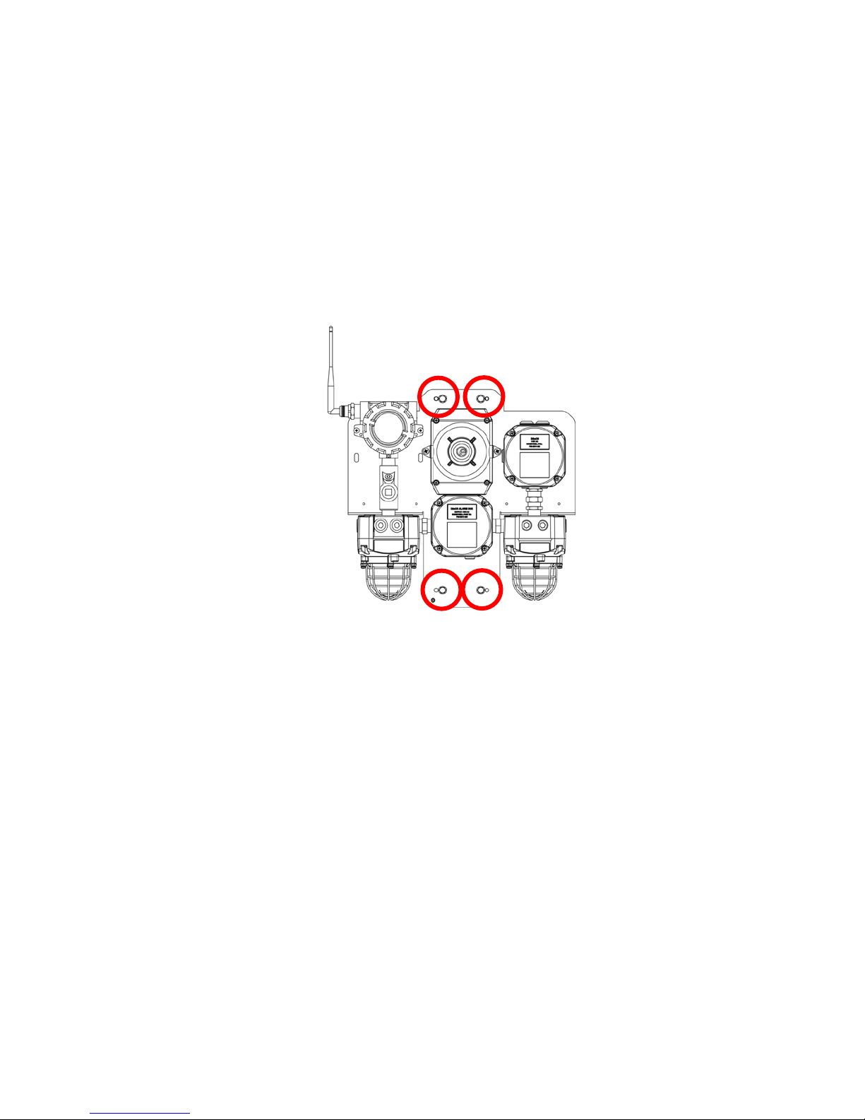
3.1.1. Mounting The Wireless Alarm Bar
When mounting the RAEPoint on a wall, use heavy-duty steel screws located as indicated below.
Follow these steps:
1. Locate the Wireless Alarm Bar on a wall or other flat surface. Make sure there is at least 12”
(30 cm) of clearance around the unit. Mark the mounting holes’ locations.
2. Remove the Wireless Alarm Bar.
3. Drill pilot holes in the wall or mounting surface.
4. Hold the Wireless Alarm Bar firmly against the wall or mounting surface and insert and tighten
the screws.
The Wireless Alarm Bar is now ready for electrical wiring and testing.
8
Page 9

Wireless Alarm Bar Installation Guide
3.1.2. Optional Pole Mounting
If it is not mounted on a wall or other flat surface, the Wireless Alarm Bar can be attached to a pole
using optional brackets (Part Number 019-2052-000).
Note: The pole must be between 1” (25mm) and 2.5” (63mm) in diameter.
Slip the screws through the two holes that are side by side in order to mount the Wireless Alarm
Bar’s plate to a vert ical pole.
Loosely assemble the clamp parts around the pole. Note that the screws have nuts that fit into the
clamp parts. The clamp parts are designed to hold the nut so that you do not need to use a wrench
on this side. Hand-tighten the parts until snug.
Use a hex wrench to tighten the hex screws from the front of the enclosure:
Once the clamp parts and the enclosure are securely held against the pole, stop tightening.
9
Page 10

Wireless Alarm Bar Installation Guide
Wires must be fed in
3.2. Wireless Alarm Bar Wiring
The Wireless Alarm Bar already has most wiring done at the factory. It is only necessary to connect
the power supply wires and grounding (according to local requirements). Power and internal
grounding wires must be fed through a connector at the bottom of the unit.
through a 1/2" NPT insert
(UL-certified). Conduit
seals are required within
IMPORTANT!
Prior to factory shipment, the RAEPoint is tested. However, the instrument should be tested after
installation.
18″ (45 cm) of conduit
entrances for Group C
hazardous locations.
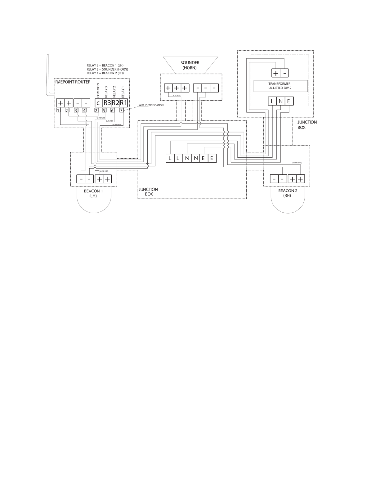
3.2.1. Complete Wireless Alarm Bar Wiring Diagram
The schematic diagram below shows internal wiring of the Wireless Alarm Bar. Refer to the
diagram on page 13 for power connections.
Note: Thermistors are pre-installed in the Junction Box to protect the relays.
10
Page 11
Wireless Alarm Bar Installation Guide
11
Page 12

Wireless Alarm Bar Installation Guide
3.2.2. Opening The Junction Box
You must remove the cover assembly from the front of the junction box in order to connect wires to
the terminal block.
Unscrew the four screws on the front of the junction box.
Before lifting the cover, gently rock it to break the seal.
Gently lift the cover away from the base of the enclosure to gain access to the interior. Not e: A
ground wire connects the cover and the base of the junction box. Be careful not to damage it.
12
Page 13
Wireless Alarm Bar Installation Guide
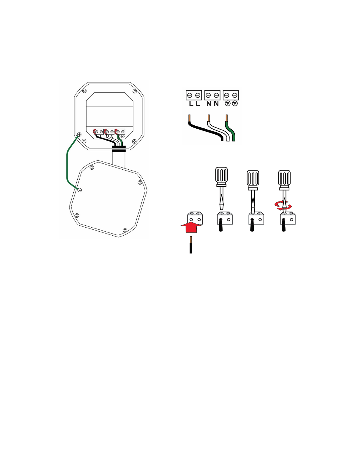
Ground
Live
Neutral
3.2.3. Connecting AC Power (Mains) Wiring
This diagram shows the wiring for external AC (Mains) power to the RAEPoint Wireless Alarm Bar.
Follow the local wire color code scheme for your region.
Note: This diagram only shows the connection points for external power and ground. For clarity, no
other wires for the Wireless Alarm Bar are shown.
Other wires are already connected to the RAEPoint and the rest of the Wireless Alarm Bar. Do not
alter them or their connections.
13
Page 14

Wireless Alarm Bar Installation Guide
Threaded
Ground
3.2.4. Reassembly
Once wiring is completed, carefully place the cover back onto the base, avoiding damage to the
mating surfaces. Make sure it is perfectly aligned with the base and then slowly tighten the four
screws.
3.2.5. External Grounding
If external or redundant grounding (earth connection) is required, a threaded post is located on
plate for wiring to ground (earth). Place the round lug from the ground wire over the threaded post
and then the split washer, flat washer, and nut. Tighten the nut and then connect the other end of
the ground wire to an appropriate grounding location.
wire
post with nut
and washers
IMPORTANT!
Prior to factory shipment, the Wireless Alarm Bar is tested. However, the instrument should be
tested after installation.
14
Page 15

Wireless Alarm Bar Installation Guide
Input Power
110 VAC 60 Hz, 35W maximum
Wireless
2.4GHz
ISM-band, IEEE 802.15.4/Mesh Radio
Transmission Range
1,000 ft (300m) typical
IP Rating
IP-65
Mechanical Interface
3/4” NPT Male
Installation
2” pipe holding or wall mounting
Temperature
-4° F to 104° F (-20° C to +40° C) (Certified)
Humidity
0 to 95% relative humidity, non-condensing
Pressure
90 to 110kPa
Status Indicators
4 LEDs (Network, Alarm, Communication, Mode)
Dimensions
17.95" L x 18.75" W x 6.9" H (456 x 476 x 173 mm)
Housing Material
Aluminum
Weight
26.5 lbs (12 kg)
Safety Compliance
UL: Class I, Division 2 Group A,B,C,D
Wireless Certification
FCC Part 15
(Contact RAE Systems for other countries)
Strobes
Two 10 Joule xenon strobes (yellow & red)
Material: Marine-grade LM6 aluminum alloy
Sounder (Horn)
112dBA at 3 ft (1m)
Material: Marine-grade aluminium Al Si12 Cu
4. Powering And Programming
Refer to the RAEPoint User’s Guide for information on how to power, test, and program the
RAEPoint. The horn and lights of the Wireless Alarm Bar are prewired, so all operations are
controlled by the RAEPoint.
5. AC-Powered Wireless Alarm Bar Specifications
The AC-Powered Wireless Alarm Bar includes the RAEPoint, as specified in the RAEPoint User’s
Guide, plus two strobe lights and a horn, as detailed below:
Specifications subject to change
R&TTE directive (1999/5/EC)
Peak Intensity: 19103 Cd (yellow), 3332 Cd (red)
15
Page 16

Wireless Alarm Bar Installation Guide
Input Power
24 to 28VDC, 35W maximum
Wireless
2.4GHz
ISM-band, IEEE 802.15.4/Mesh Radio
Transmission Range
1,000 ft (300m) typical
IP Rating
IP-65
Mechanical Interface
3/4” NPT Male
Installation
Wall mounting
Temperature
-4° F to 120° F (-20° C to +50° C) (Certified)
Humidity
0 to 95% relative humidity, non-condensing
Pressure
90 to 110kPa
Status Indicators
4 LEDs (Network, Alarm, Communication, Mode)
Dimensions
17.95" L x 18.75" W x 6.9" H (456 x 476 x 173 mm)
Housing Material
Aluminum
Weight
26.5 lbs (12 kg)
Safety Compliance
ATEX: II 3G Ex T2 G c (Zone 2)
UL: Class I, Division 2 Group A,B,C,D
Wireless Certification
FCC Part 15
(Contact RAE Systems for other countries)
Strobes
Two 10 Joule xenon strobes (yellow & red)
Material: Marine-grade LM6 aluminum alloy
Sounder (Horn)
112dBA at 3 ft (1m)
Material: Marine-grade aluminum Al Si12 Cu
6. DC-Powered Wireless Alarm Bar Specifications
The DC-Powered Wireless Alarm Bar includes the RAEPoint, as specified in the RAEPoint User’s
Guide, plus two strobe lights and a horn, as detailed below:
R&TTE directive (1999/5/EC)
Peak Intensity: 19103 Cd (yellow), 3332 Cd (red)
Specifications subject to change
Brazil Radio Specifications
Radio model: RM900A
Frequency range: Within 902 to 907.5 MHz and 915 to 928 MHz, use IEEE 802.15.4 channel 1, 6,
7, 8, 9 and 10
Modulation: 802.15.4 DSSS BPSK
RF power(Tx): 20dBm
Data rate: 40kbps
Radio model: RM2400A
Frequency range: 2.400 to 2.4835GHz
Modulation: 802.15.4 DSSS BPSK
RF power(Tx): 20dBm
Data rate: 250kbps
16
Page 17

Wireless Alarm Bar Installation Guide
US
Cl. I Div 2, Group C, D
Wireless Approval For QATAR In Middle East
ictQATAR
Type Approval Reg. No.: R-4697
Type Approval Reg. No.: R-4465
Wireless Approval For UAE In Middle East
TRA REGISTERED N o: ER36636/15
DEALER No: HONEYWELL INTERNATIONAL MIDDLE EAST - LTD - DUBAI BR
TRA REGISTERED N o: ER36063/14
DEALER No: HONEYWELL INTERNATIONAL MIDDLE EAST - LTD - DUBAI BR
Hazardous Location Applic a t ion
The Wireless Alarm Bar includes multiple components (RAEPoint, junction box, t wo strobe li ghts ,
and one horn). The table below shows suitable application based on the components for the
combined system.
17
Page 18

Europe, Middle East, Africa
Americas
Asia Pacific
For more information
www.honeywellanalytics.com
www.raesystems.com
Life Safety Distribution GmbH
Tel: 00800 333 222 44 (Freephone number)
Tel: +41 44 943 4380 (Alternative number)
Fax: 00800 333 222 55
Middle East Tel: +971 4 450 5800
(Fixed Gas Detection)
Middle East Tel: +971 4 450 5852
(Portable Gas Detection)
gasdetection@honeywell.com
Honeywell Analytics
Distribution Inc.
Tel: +1 847 955 8200
Toll free: +1 800 538 0363
Fax: +1 847 955 8210
detectgas@honeywell.com
RAE Systems by Honeywell
Phone: 408.952.8200
Toll Free: 1.888.723.4800
Fax: 408.952.8480
Honeywell Analytics Asia Pacific
Tel: +82 (0) 2 6909 0300
Fax: +82 (0) 2 2025 0328
India Tel: +91 124 4752700
analytics.ap@honeywell.com
Technical Services
EMEA: HAexpert@honeywell.com
US: ha.us.service@honeywell.com
AP: ha.ap.service@honeywell.com
F08-4007-000
RevB August 2018
© 2018 Honeywell International
 Loading...