

Page 1
XYR 5000 WG510/WA510
Wireless Gauge and Absolute Pressure Transmitters
34-XY-01-01 10/2003 PRODUCT SPECIFICATION AND MODEL SELECTION GUIDE
Function
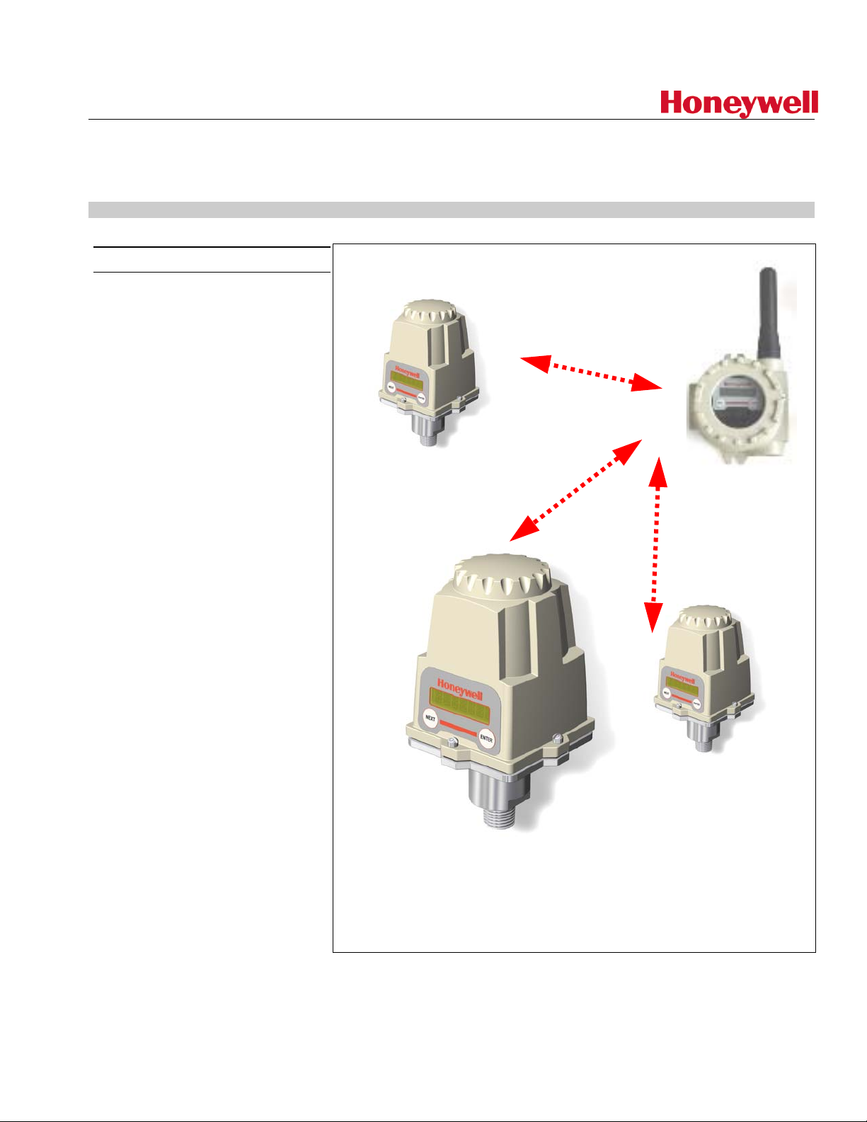
The WG/A510 is part of the XYR
5000 family of wireless products.
These transmitters cover a wide
pressure range, and can be used to
monitor a variety of processes and
assets in hazardous and remote
areas. Since there are no wires to
run, the transmitter can be installed
and operational in minutes, quickly
providing information about the
variable being monitored. The Smart
Response Manager allows the
transmitter to adapt to changing
process conditions, allowing greater
visibility to process variation. Smart
Response Manager allows the user
to set thresholds which, when
exceeded, cause the transmitter to
adjust sampling and data
transmission rates.
The transmitter combines a high
accuracy piezoresistive sensor with
a Radio Frequency (RF) transceiver
that communicates in a digital
protocol, using Frequency Hopping
Spread Spectrum (FHSS). FHSS
ensures data integrity by continually
switching the carrier wave over a
wide range of frequencies. Power is
supplied by a C size 3.6 V lithium
battery, with an expected lifetime of
up to five years.
Enjoy the benefits of wireless
technology today:
Base Radio
Wireless
Transmitters
Improve Product Quality, Ensure
High Uptime, Reduce Maintenance
and Operational Costs, Meet
Regulatory Requirements, and
Enhance Flexibility.
Page 2

MODELS
Gauge Pressure
Model #
WG511
WG512
WG513
WG514
Absolute
Pressure
Model #
WA515
WA516
WIRELESS GENERAL SPECIFICATIONS
Wireless Communication
UPPER RANGE
LIMIT
PSIG PSIG
0 - 30 60 316L SS/316 SS
0 - 250 500 316L SS/316 SS
0 - 1000 2000 316L SS/316 SS
0 - 5000 12000 17-4 pH/316 SS
UPPER RANGE
LIMIT
PSIA PSIA
0 - 30 60 316L SS/316 SS
0 - 250 500 316L SS/316 SS
902 MHz – 928 MHz Frequency Hopping Spread Spectrum (FHSS)
OVERLOAD LIMIT DIAPHRAGM/BODY MATERIAL
(wetted parts)
OVERLOAD LIMIT DIAPHRAGM MATERIAL
FCC certified ISM license-free band.
Every data block transmitted is verified (CRC check) and acknowledged by the
Base Radio.
RF Transmit Power
Data Rate
Antenna
Signal Range
*Actual range may vary depending on site topography.
SELF DIAGNOSTICS
Self-checking software and hardware that identifies and reports out of spec conditions, and field unit low battery
voltage.
OPERATING/STORAGE CONDITIONS
Humidity
Temperature Ambient Sensor:
31 mW, 17.8 mW typical.
Configurable: 4.8 Kbps, 19.2 Kbps, or 76.8 Kbps.
Internal 3” omni-directional, ¼ wave, monopole.
Up to 2000 feet (600 meters) from Base Radio with clear line of sight.*
99% RH (non-condensing).
-40 to +230°F (-40 to +110°C)
Ambient Electronics:
Process fluid:
Display (Full visibility):
-40 to +185°F (-40 to +85°C)
-40 to +250°F (-40 to +121°C)
-4 to +158°F (-20 to +70°C)
Page 2 of 5
Display (Reduced visibility):
Storage:
-40 to +185°F (-40 to +85°C)
-58 to +185°F (-50 to +85°C).
Page 3

DEVICE CONFIGURATION
Parameter Configuration
• RF Channel Setup: 1 to 16.
• Baud Rate: 4.8 Kbps, 19.2 Kbps, 76.8 Kbps.
• RF ID: 1 to 50.
• Password.
• Tag Name (up to 21 characters).
• Normal Transmit Rate: (1–5 sec, 10 sec, 15 sec, 20 sec, 40 sec, 1
min).
• Normal Sampling Rate: (1–10 sec, 15 sec, 20 sec, 30 sec, 1 min).
• Abnormal Transmit Rate: (1–5 sec, 10 sec, 15 sec, 20 sec, 40
sec, 1 min).
• Abnormal Sampling Rate: (1–10 sec, 15 sec, 20 sec, 30 sec).
• Pressure Normal Upper Value: Disabled/Enabled. Enabled to
change Sampling and Transmit rates during abnormal process
conditions.
• Pressure Normal Lower Value: Disabled/Enabled. Enabled to
change Sampling and Transmit rates during abnormal process
conditions.
• Engineering Units: PSI, bar, mBar, Pa, kPa, Torr, Atm, inH20,
inHg, ftH20, mmHg, g/cm2, kg/cm2.
• Pressure Zero.
• Offset: User defined offset will be transmitted instead of actual
• Trim: Applies a user-defined one- or two-point correction curve to
Configuration Panel
PERFORMANCE
Accuracy (linearity and
hysteresis)
Combined Zero and Span Stability
Resolution
PHYSICAL SPECIFICATIONS
Process connections
Base Material (bob-wetted)
Electronic Housing
Vibration and Shock
Integrated LCD display with membrane switch buttons for local configuration.
LCD display is 7-digit (alternating) high contrast, anti-reflective monochrome.
Display cycles between pressure level and RF status.
±0.1% FS over temperature.
Less than ±0.1% of sensor URL per year @ 21°C (70°F).
24-bit A/D converter.
1/2" - NPTM.
304 SS
GE Lexan. V0 Rating and UV Stable.
Certified per IEC EN00068 2-6 (Vibration) and 2-27 (Shock)
value.
the actual value.
Random Vibration
Net weight
Electromagnetic Compatibility (CE
Compliance)
Page 3 of 5
Certified to withstand 6 g’s, 15 minutes per axis from 9 – 500 Hz.
1 kg (2 lbs).
Operates within Specifications in fields from 80 to 1,000 MHz with Field
Strengths to 30 V/m. Meets EN 50082-1 General Immunity Standard and EN
55011 Compatibility Emissions Standard.
Page 4

APPROVALS
Environmental protection
Electrical classification
DIMENSIONS
NEMA 4X (pending)..
FM Rated Intrinsically Safe for Class I, Div. 1, Groups A,B,C,D; Class II, Div. 1,
Groups E,F,G; Class III, Div. 1 (pending)..
Page 4 of 5
Page 5

Model Selection Guide
s
P
itters
_
_
Model Selection Guide
XYR 5000 Wireles
ressure Transm
Model Selection Guide
34-XY-16-01 Issue 0
Instructions
Select the desired key number.
Key Number
_ _ _
KEY NUMBER Selection
Description
Gauge Pressure Transmitter 0 - 0.3 to 0 - 30 PSIG WG511
Gauge Pressure Transmitter 0 - 2.5 to 0 - 250 PSIG WG512
Gauge Pressure Transmitter 0 - 10 to 0 - 1000 PSIG WG513
Gauge Pressure Transmitter 0 - 50 to 0 - 5000 PSIG WG514
Span
Honeywell Confidential & Proprietary
Absolute Pressure Transmitter 0 - 0.3 to 0 - 30 PSIA WA515
Absolute Pressure Transmitter 0 - 2.5 to 0 - 250 PSIA WA516
Industrial Measurement and Control
Honeywell International Inc.
2500 West Union Hills Drive
Phoenix, Arizona 85027 Honeywell International Inc.
Page 5 of 5
 Loading...