

Page 1

HONEYWELL EXCEL 5000 OPEN SYSTEM
BEFORE INSTALLATION
The W7070A2000 ZAPP Wireless Receiver (including the
ZAPP External Antenna) is capable of exchanging data with
the following four types of ZAPP room units:
• The RT7070A2008 ZAPP Wireless Handheld Remote
Control
• the T7270A2001 ZAPP Wireless Wall Module with
temperature sensor and setpoint;
• the T7270A2019 ZAPP Wireless Wall Module with
temperature sensor; and
• the T7270B2009 ZAPP Wireless Wall Module for HAVC,
light, and sunblind applications.
The W7070A2000 is suitable for use with up to eight rooms in
which the aforementioned ZAPP room units are in operation.
The W7070A2000 ZAPP Wireless Receiver receives data
from the ZAPP room units at 868.3 MHz.
STANDARDS AND NORMS
The ZAPP System complies with CE and EN 300 220-1 and
EN 301 489-1 as well as L
Guidelines Version 3.2.
IMPORTANT!
It is recommended that devices be kept at room
temperature for at least 24 hours before applying
power to allow any condensation resulting from low
shipping/storage temperatures to evaporate.
Use in Combination with Legacy Devices
The W7070A2000 ZAPP Wireless Receiver is suitable for use
only with the T7270A2001, T7270A2019, T7270B2009 ZAPP
Wireless Wall Modules and the RT7070A2008 ZAPP Wireless
Handheld Remote Control. It cannot communicate with (but is
likewise unaffected by) legacy devices (e.g. the T7270A1001,
T7270A1019, T7270B1009, or the RT7070A1008).
Set-Up
Because of interference from other devices and the building
structure, it is not possible to exactly define the wireless
transmission range. For further details, see section
"Installation of Wireless Systems" on page 3.
ONMARK® Application Layer
LonWorks Communications
The W7070A2000 utilizes a free-topology transceiver
(FTT10A) Link Power compatible L
allows daisy-chain, loop, and star network configurations or
any combination thereof.
Depending upon the L
one or two termination modules may be required (see Fig. 4).
Different connections to the termination module are
necessary, depending upon whether it is used in a single- or
double-terminated network configuration. For more
information, please see “LonWorks Mechanisms” (EN1B0270GE51).
NOTE: The L
Wire the W7070A2000's LonWorks ® communications
network using level IV 22 AWG or plenum-rated level IV 22
AWG non-shielded, twisted pair, solid conductor wire.
INSTALLATION
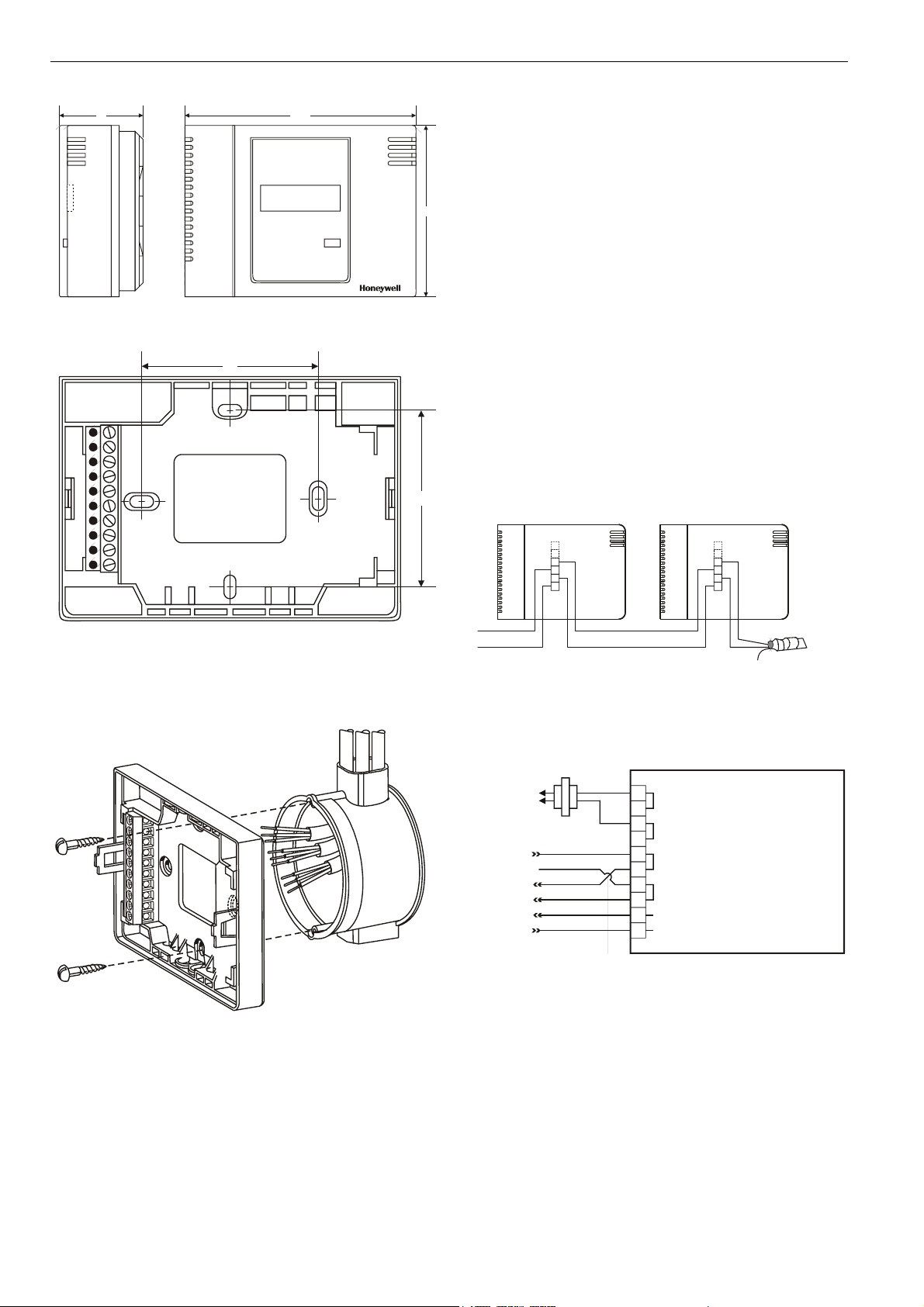
See Fig. 1 for outside dimensions and Fig. 2 for sub-base
mounting dimensions. The W7070A2000 can be mounted in
any orientation desired on a panel, wall, or onto a standard
wall outlet box (see Fig. 3).
Power
Input power provided must be 24 Vac (±20%), 50 or 60 Hz.
The power consumption of the W7070A2000 (including the
connected active antenna) is 2 VA.
Use the heaviest gauge wire available, up to 14 AWG
(2.5 mm
wiring.
W7070A2000
ZAPP WIRELESS RECEIVER
INSTALLATION INSTRUCTIONS
ONWORKS
ONWORKS
ONWORKS
eliminating installation errors due to miswiring
®
network configuration used,
®
network is insensitive to polarity,
CAUTION
Avoid electrical shock or equipment damage. Turn
power OFF prior to connecting to or removing connections from any terminals.
2),
with a minimum of 18 AWG (1.0 mm2) for all power
®
network that
® U.S. Registered Trademark
Copyright © 2009 Honeywell Inc. • All Rights Reserved EN1B-0396GE51 R0409B
Page 2
W7070A2000 ZAPP WIRELESS RECEIVER
11642
Fig. 1. W7070A2000, outside dimensions (in mm)
60
60
Wiring Details
Fig. 5 illustrates the terminal assignments of the
W7070A2000. Refer to job drawings for specific wiring
diagrams. Connections to the W7070A2000 are made at an
internal terminal block accessible beneath the front cover. No
tools are required to remove the front cover.
86
1. Simply pull away the cover from the sub-base as shown in
Fig. 6.
Use a minimum wire size of 20 AWG (0.5 mm
output connections. The maximum length of all input / output
cables is 20 m.
Wire to the terminal blocks as follows:
2. Strip 13 mm insulation from the conductor.
3. Insert the wire in the required terminal location and tighten
the screw to complete the termination.
4. Ensure that the wire entering the terminal block does not
extend above the numbered face of the terminal block to
avoid contact between the wires and the printed circuit
board on the underside of the front cover (see Fig. 7).
5
6
7
8
2
) for all input /
5
6
7
8
Fig. 2. Sub-base mounting dimensions (in mm)
1
2
3
4
5
6
7
8
9
10
Fig. 3. Mounting on wall outlet box
Fig. 4. Termination module connection (daisy-chain
120/240 VAC
LONW
L
ONWORKS
ZAPP External Antenna
BROWN
ORANGE
TERMINATION
MODULE (209541B)
network configuration)
W7070A2000
ORKS
NETWORK IN
NETWORK OUT
24 VAC
24 VAC COM
24 VAC
1
24 VAC
2
3
24 VAC
4
24 VAC
5
LonWorks
6
LonWorks
7
LonWorks
8
LonWorks
9
ZAPP EXTERNAL ANTENNA BUS-
10
ZAPP EXTERNAL ANTENNA BUS+
Fig. 5. W7070A2000 terminal assignments
EN1B-0396GE51 R0409B
2
Page 3

W7070A2000 ZAPP WIRELESS RECEIVER
ZAPP EXTERNAL ANTENNA
Each W7070A2000 is delivered together with a corresponding
ZAPP External Antenna, to which it must be connected before
it can receive signals from the ZAPP devices.
Install the ZAPP External Antenna only outside of metal
housings (e.g. control cabinets).
Fig. 6. Terminal cover removal
88
1
2
3
4
5
6
7
8
9
10
Fig. 7. Terminal box connections
Environmental Ratings
Operating Temperature
(0…50 °C).
Shipping/Storage Temperature
(-20…70 °C).
Relative Humidity
5…95 % non-condensing
Receiver Class
The ZAPP External Antenna (Receiver Class 2) is an
active electronic element. It broadcasts no electromagnetic energy. Communication between the ZAPP
External Antenna and the W7070A2000 is via bus (see
also Fig. 9).
Housing
IP20
83
Fig. 8. ZAPP External Antenna, dimensions (mm)
Install the ZAPP External Antenna at a suitable location near
(i.e. within 30 m) of the W7070A2000.
ZAPP External Antenna W7070A2000
28
max. 30 m
Fig. 9. Max. distance
The ZAPP External Antenna may be connected to only a
single W7070A2000.
See also section "ZAPP External Antenna – Installation and
Wiring" on page 6.
Installation of Wireless Systems
Due to the use of wireless technology for sending signals from
transmitters i.e. ZAPP room units to evaluation units
(receivers) and the discontinuation of the use of electrical
cable connections, there are some basic guidelines that must
be followed during planning and installation.
This information is intended to help both the planner with
configuring the radio path and the system integrator/engineer
or service technician with installation and troubleshooting.
EN1B-0396GE51 R0409B
3
Page 4

W7070A2000 ZAPP WIRELESS RECEIVER
X
X
Basics for Radio Signals in Buildings
Radio signals are electromagnetic waves and as such
diminish in strength on their way from the transmitter to the
receiver, even when unobstructed. This drop in signal
strength is inversely proportional to the square of the distance
between the transmitter and the receiver.
SIGNAL STRENGTH
DISTANCE
ZAPP
RM. UNIT
Fig. 10. Attenuation of signal strength with distance
ZAPP
ANTENNA
Physical Obstructions
Beside this natural (distance-dependent) drop in signal
strength, the presence of physical obstructions (e.g. walls,
metallic objects, reinforcements in walls, metallized foils of
thermal insulations or metallized heat-absorbent glass)
located between the transmitter and the receiver can further
weaken signal strength. This is referred to as "damping
attenuation."
It is true that radio waves can penetrate walls to an extent, but
the resultant drop in signal strength is greater than with
unobstructed propagation in the free field.
Here are some examples of the blocking effect of different
types of walls:
Table 1. Blocking effect of different wall materials
material penetration
wood, gypsum, uncoated glass without metal 90...100%
brick, pressboard 65...95%
reinforced concrete with iron reinforcement 10...90%
metal, aluminum pasting 0...10%
In actual practice, this means that the building material used
in a building is of paramount importance for the evaluation of
the transmitting range. For an evaluation of the environment,
some standard values are listed:
Table 2. Evaluating installation environment
pathway typical range
unobstructed direct line
of sight
gypsum wall/wood 25 m through max. 4 walls
brick wall/gas concrete 15 m through max. 2 walls
reinforced concrete
walls/ceilings
NOTE: Storage areas and elevator shafts should be
regarded as obstructions.
ZAPP
RM. UNIT
Fig. 11. Obstruction of signal
Likewise, avoid mounting the antenna and transmitter such
that the radio waves travel along walls (see Fig. 12).
ZAPP
RM. UNIT
Fig. 12. Attenuation of signal strength at walls
30 m in passages, corridors, up to
100 m in halls
10 m through max. 1 wall/ceiling
ZAPP
ANTENNA
SHEET
METAL
ZAPP
ANTENNA
ZAPP
ANTENNA
ZAPP
ANTENNA
ZAPP
ANTENNA
EN1B-0396GE51 R0409B
4
Page 5

W7070A2000 ZAPP WIRELESS RECEIVER
Distance to Other Interference Sources
A distance between the ZAPP room units and other (thirdparty) transmitters (e.g. GSM / DECT / wireless LAN) of at
least 1 m should be maintained.
ZAPP
ANTENNA
ZAPP
ANTENNA
3RD-PARTY
TRANSMITTER
X
MIN. 1 m
ZAPP
RM. UNIT
Fig. 13. Distance to interference sources
Further, a minimum distance of 35 cm should be maintained
between different ZAPP components (i.e. ZAPP External
Antennas, ZAPP Wall modules, and ZAPP Handhelds; it is, of
course, no problem if a ZAPP External Antenna and a
W7070A2000 Wireless Receiver are closer together).
X
Mounting Of Receiving Antenna
Ideally, an external receiving antenna should be mounted at a
central location in the room. If possible, the antenna should
have a distance of min. 0.1 m (min. λ/4, example: at 868 MHz
≈ 9 cm) to the wall and 0.5 m to the ceiling.
CEILING
MIN. 0.5 m
3RD-PARTY
TRANSMITTER
Troubleshooting
Table 3. Possible causes of trouble and measures
error possible cause measure
ZAPP Ext.
Antenna
never receiving
signal.
ZAPP Ext.
Antenna
sometimes
not receiving
signal.
ZAPP
Receiver
displays
invalid
values on
L
ONWORKS
interface.
ZAPP room unit not
transmitting.
Distance between
ZAPP room unit and
ZAPP Ext. Antenna
beyond limit.
Improper connection of
ZAPP Ext. Antenna.
ZAPP room unit not
taught-in.
Wrong ZAPP room unit
taught-in.
ZAPP room unit
removed.
Mounting place of the
ZAPP room unit has
been changed.
Change of ambient
conditions (metal
cabinets, door, equipment, people,
jamming).
Distance between
ZAPP room unit and
ZAPP Ext. Antenna at
limit.
ZAPP room units have
been taught in and,
afterwards, ZAPP
Receiver has been recommissioned.
Check ZAPP room unit
as described above.
Decrease distance.
Check routing of cable
between ZAPP Ext.
Antenna and ZAPP
Receiver.
Renewed teaching-in
of ZAPP room unit to
ZAPP Receiver.
Renewed teaching-in
of ZAPP room unit to
ZAPP Receiver.
Renewed teaching-in
of ZAPP room unit to
ZAPP Receiver.
Shift ZAPP room unit
or ZAPP Ext. Antenna.
Ensure min. distance
to interference source;
remove obstructions.
Shift ZAPP room unit
or ZAPP Ext. Antenna.
Decrease distance.
Force updating by
operating adjustment
wheel of every taughtin ZAPP Wall Module
or pushing setpoint key
of every taught-in
ZAPP Handheld.
ZAPP
ANTENNA
Fig. 14. Positioning antenna in ceiling area
EN1B-0396GE51 R0409B
5
Page 6

W7070A2000 ZAPP WIRELESS RECEIVER
ZAPP External Antenna – Installation and Wiring
1 2
2
1
3 4
ZAPP External Antenna W7070A2000
2
12
9
10
1
2
1
JE-LiYCY 2x2x0.5 mm²
1/10
2/9
Manufactured for and on behalf of the Environmental and Combustion Controls Division of Honeywell Technologies Sàrl, Rolle, Z.A. La Pièce 16, Switzerland by its Authorized Representative:
Honeywell GmbH
Böblinger Strasse 17
71101 Schönaich, Germany
Tel.: (++49) (0) 7031 637 01
Fax: (++49) (0) 7031 637 493
http://ecc.emea.honeywell.com
Subject to change without notice. Printed in Germany
This document is definitive for the enclosed product and replaces all previous publications.
Honeywell Inc. hereby declares that this device complies with the basic requirements and other relevant regulations of guideline 1999/5/EC. The declaration of
conformity of the product can be requested from the manufacturer.
Note to non-E.U. countries: This product may only be used if operation in the 868 MHz frequency band is permissible.
EN1B-0396GE51 R0409B
or
JE-Y(St)Y 2x2x0.8mm²
or
2x0.5mm²JE-Y(St)Y
 Loading...