

Honeywell VTL120 Installation Instruction
e
n
e
r
g
y
www.energysavingtrust.org.uk
g
n
i
v
a
s
VTL120
Reversible Flow Radiator Thermostat
Installation Instruction
1. Notes and Safety instructions
These products are approved to the
European CEN standard EN215, which
supersedes BS 6284.
Whilst Honeywell takes all reasonable practical
steps to design and manufacture its products to
comply with the requirements of the Health and
Safety at Work Act 1974 all products must be
properly used and purchasers are reminded that
their obligations under the Act are to ensure that
the installation and operation of such products
at a place of work should be safe and without
risk to health.
Honeywell reserves the right at any time and
without notice to change any product or any
information contained in this publication.
1.2 Check list
• Check all connections for securing and leakes.
• Use clean pipework, free from swarf.
• Consider the use of an automatic by-pass
valve (e.g. Honeywell DU145) to ensure the
specification is adherded to.
• Don’t allow heat from blow torch onto body.
• Don’t install the valve in a position which is
subject to draughts, sun radiation or behind
curtains.
• Don’t overtighten the head/body connection,
as the insulating sleeve may become damaged.
2. Location
The thermostat can be fitted in any orientation
with the flow through the body in either
direction.
3. Technical Data
Maximum working pressure 10 bar (140 psi)
Closing time 20 minutes
To ensure that the valve will thermostatically
close the differential pressure must not
exceed 1.0 bar.
Maximum differential pressure to ensure
reliable and quiet operation is 0.2 bar.
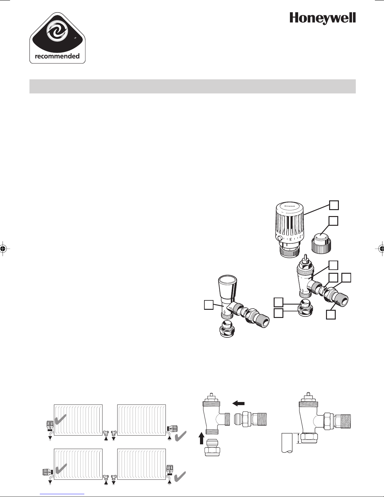
4. Component parts
1
1 Wheelhead
2 Decorators Cap
2
3 Valve body
4 Tail piece
5 Olive
6 Nut
7 Lockshield valve
3
5
7
5
6
4
5. Installation
5.1 Fitting - valve connections
1. Fit the connection fittings to the valve.
2. Cut copper tube to entry depth of 10 mm.
6
EB-VTL120; 04 100 50 001 000
10 mm
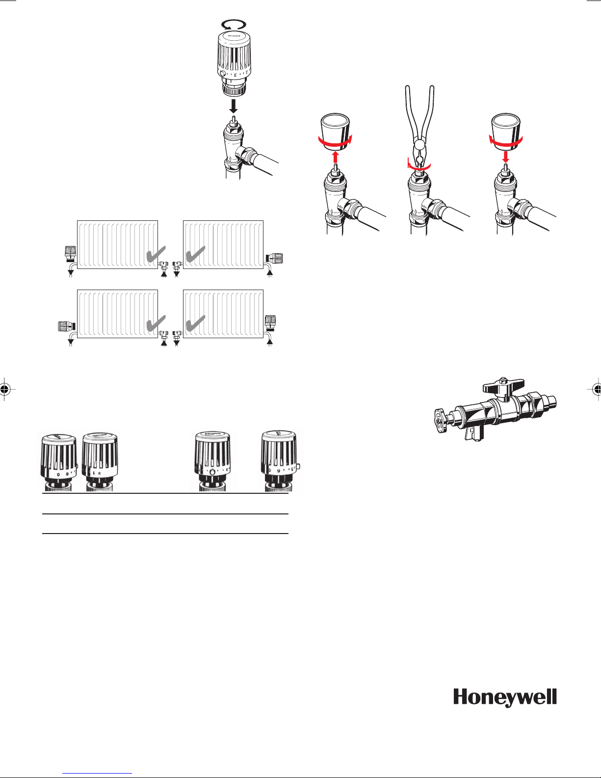
5.2 Head to body
1.Turn head to open position.
2.Position head so indicator is
facing user.
3.Screw on head, ensuring lugs
and slots engage as collar
is tightened.
5.3 Lockshield valve
1.Install the lockshield valve opposite from
thermostat
6. Adjustment / Setting of thermostat
The VT117E is adjustable by turning the top
anti-clockwise to increase temperature setting
or clockwise to decrease temperature setting.
7. To shut off the lockshield valve
1.Unscrew and remove cover cap.
2.Turn the spindle clockwise till stop by using a
pliers
3.Fit cover cap.
8. Service
8.1 Decorator cap
When removing the radiator for any reason
the decorators cap supplied with the valve
should be used to isolate the flow.
8.2 Servicing
Use the service tool VA8200A001 for cleaning
or replacement of the valve seating without
draining the system.
For further informations
see seperate manual.
0
123 ● 56
*
closed 6°C 8°C 12°C 16°C 20°C 23°C 26°C
These temperatures are for guideance only
and are based on horizontal mounting on the
flow pipe. If the radiator thermostat is installed
in any other direction then the temperature will
vary by 1°C to 2°C.
Note: Heating can freeze when thermostats
with zero position are set at position „0“.
Honeywell Control Systems Ltd.
Honeywell House
Arlington Business Park
Bracknell, Berkshire RG12 1EB
Phone: 01344 656000
Fax: 01344 656240
9. Disposal
Observe the local requirements regarding
correct waste recycling/disposal.
www.honeywelluk.com
EN3H-0315GE25R1105
 Loading...