

Honeywell VT15 Installation And User Instruction
VT15
Standard Radiator Thermostat
Installation and User Instruction
1. Additional Information
What is a thermostatic radiator valve (TRV)?
..an explanation for householders
TRVs sense the air temperature around them and
regulate the flow of water through the radiator which they are fitted
to. They do not control the boiler.
TRVs sense the air temperature around them and regulate the flow
of water through the radiator which they are fitted to. They do not
control the boiler.
They should be set at a level that gives you the room temperature
you want. These settings may have to be different in each room,
and should set the TRVs to suit each room an then leave them to
do their job.
Turning a TRV to a higher setting will not make the room heat up
any faster. How quickly the room heats up depends on the boiler
size and setting, and the radiator size. Turning the TRV to a lower
setting will result in the room beiing controlled at a lower temperature, and saves energy.
TRVs need a free flow of air to sense the temperature, sp they must
not be covered by curtains or blocked by furniture.
TRVs cannot turn off the boiler when the whole house is warm. To
do that, you will need a room thermostat as well. The radiator in the
room with the romm thermostat should normally have a TRV, but, if
it does, keep the TRV on the maximum setting and adjust the room
thermostat as explained with the instructions.
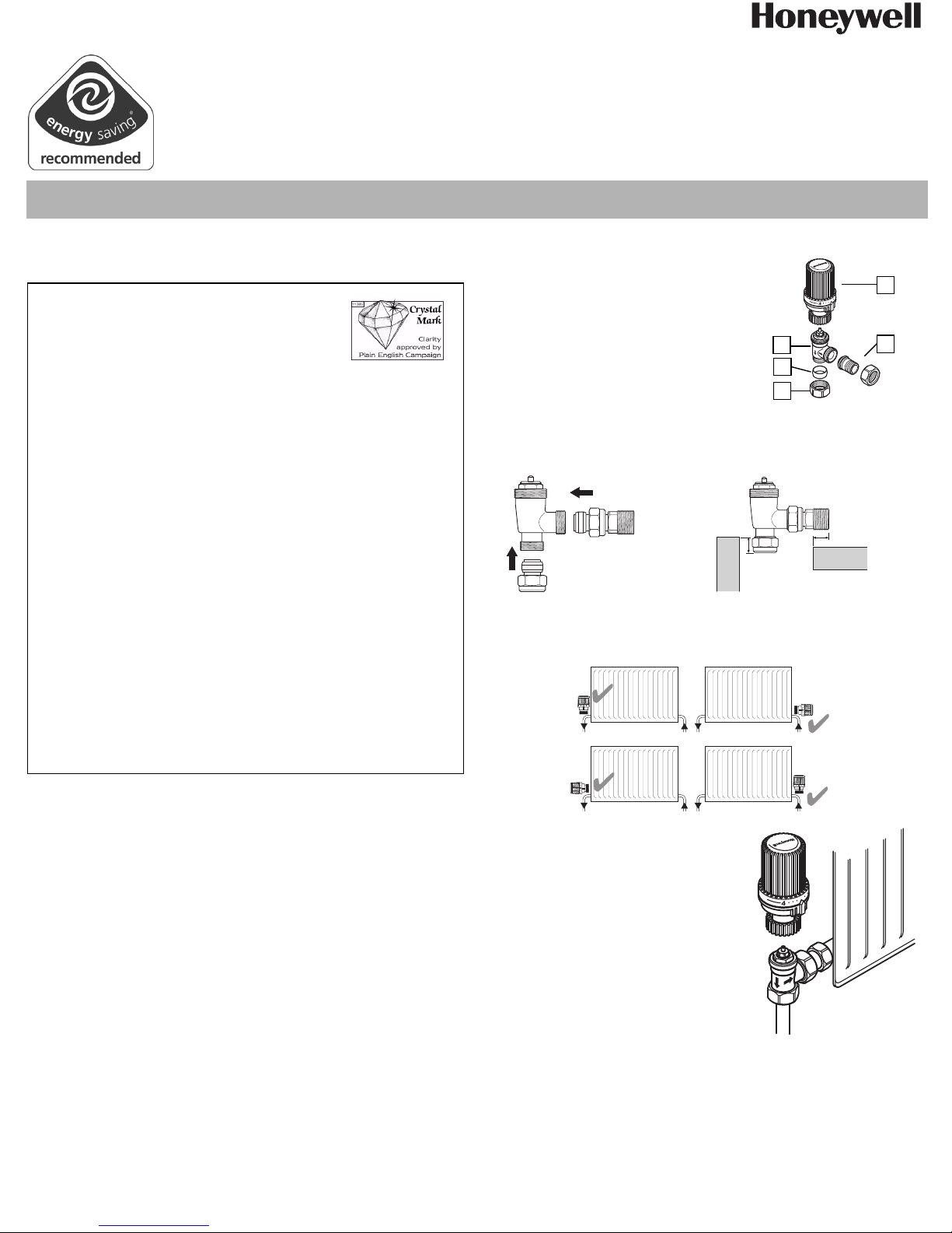
4. Component parts
1. Thermostatic Head
2. Valve Body
3. Tailpiece
4. Olive
5. Nut
5. Installation
5.1. Fitting - valve connections
1. Fit the connection fittings to the valve.
2. Cut copper tube to entry depth of 10 mm.
10mm
5
3
2
4
5
1
3
10mm
6. Location
The thermostat can be fitted in any orientation with the flow through the
body in either direction.
2. Notes and Safety instructions
Whilst Honeywell takes all reasonable practical steps to design and
manufacture its products to comply with the requirements of the Health
and Safety at Work Act 1974 all products must be properly used and
purchasers are reminded that their obligations under the Act are to
ensure that the installation and operation of such products at a place of
work should be safe and without risk to health.
Honeywell reserves the right at any time and without notice to change
any product or any information contained in this publication.
3. Functional Description
The VT15 Standard Radiator Thermostat will control the air temperature of the room in which they are situated from a range of 6°C to
26°C.You can choose the temperature that exactly suits your needs.
Different rooms can be controlled at different temperatures, depending
on their use. For example, the bathroom can be warmer or cooler than
other rooms where the VT15 is installed and so on.
The VT15 will also save you money by turning the radiator down, or closing off, when other sources of heat are warming the room. Such
sources of heat are televisions, sunshine and even people.
50036790-001
Honeywell y Subject to change EN2H-2123GE25 R1108
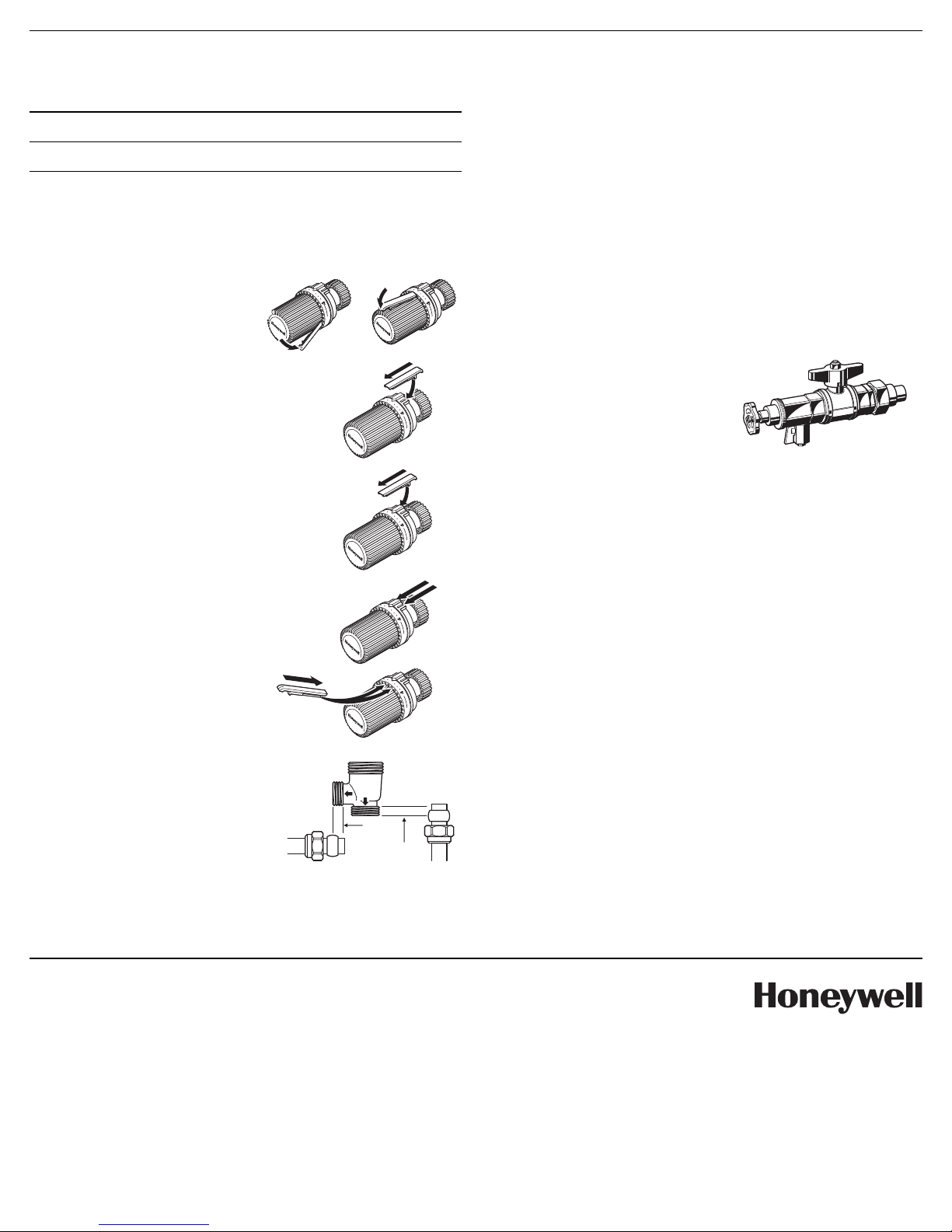
7. Body to head connection
Initially adjust the thermostat to No. 5
then hold the thermostat so that the
position indicator on the thermostatic
head is facing the user.
Screw the thermostatic head to the
valve body, ensuring that the thermostatic head is located fully over the large
hexagonal nut. A slight downward force
will be necessary to do this.
5
3
VT15
8. Temperature Scale
The VT15 is adjusted by turning the top anticlockwise to increase the
temperature setting or clockwise to decrease the temperature setting.
6°C 10°C 15°C 20°C 23°C 26°C
0*12345
Thermostatic off
Frost
Position
Normal
Setting
These temperatures are for guidance only and may vary slightly depending on the nature of the installation.
9. Using the “Memory Clip“
3
3
1. Remove “Memory Clip” and fit
into required setting Position
5
5
10. Temperature limiting
To set the upper limit:
1. Set to the required value and insert the right
hand stop bar with the “Memory Clip”
To set the lower limit:
1. Set to the required value and insert the left
hand stop bar with the “Memory Clip”
3
5
3
5
11. Temperature locking
1. Set to the required value and insert the
right and left hand stop bars with the
“Memory Clip”
12. Removal of temperature
limits and locking
1. Remove stop bars with the
“Memory Clip“
3
5
3
5
13. Fitting Valve Connections
Copper Connections
1. Cut copper tube to an entry depth
of 8mm
Radiator Connections
1. Screw 1/2’’ BSP tailpiece into the
tapping on radiator.
8mm
OR
8mm
14. Specification
Maximum flow temperature 130°C (266°F)
Maximum working pressure 10 Bar (150psi)
To ensure that the valve will thermostatically close the differential pres-
sure must not exceed 1.0 bar.
Maximum differential pressure to ensure reliable and quiet operation is
0.2 bar.
Hystersis <1.0k
Heat conduction 0.6k
Change in differential pressure 0.4k
Closing time 20 mins
CEN Approved EN215
15. Servicing
Use the service tool VA8200A001 for
cleaning or replacement of the valve
seating without draining the system.
For further informations see seperate
manual.
16. Radiator Removal
If it is necessary to remove the radiator for decorating or other reasons,
ensure that the thermostatic head is positioned at the `0´ position.
However, if the temperature in the room falls below 6°C, the thermostat
will open.
If there is any possibility that the temperature in the room will fall below
6°C, then the decorators cap supplied with the valve should be used to
isolate the flow.
17. Check list
• Check all connections for securing and leaks.
• Use clean pipework, free from swarf.
• Consider the use of an automatic by-pass valve
(e.g. Honeywell DU145) to ensure the specification is adherded to.
• Don’t allow heat from blow torch onto body.
• Don’t install the valve in a position which is subject to draughts, sun
radiation or behind curtains.
• Don’t overtighten the head/body connection, as the insulating sleeve
may become damaged.
NOTE: Ensure that the foam insert located in the thermostatic head
is in place in the head before the head is attached to the
valve body.
London Office
Honeywell Control Systems Ltd.
Honeywell House
Arlington Business Park
Bracknell, Berkshire RG12 1EB
T (0 13 44) 65 60 00
F (0 13 44) 65 62 40
www.honeywell.com/uk
EN2H-2123GE23 R1108
November 2008
© 2008 Honeywell International Inc.
Subject to change without notice
Manufactured for and on behalf of the Environmental and Combustion Controls Division of Honeywell Technologies Sàrl, Rolle, Z.A.
La Pièce 16, Switzerland or its authorized representative.
 Loading...