Honeywell VBF2 Catalog Page

Honeywell VBF2 Catalog Page

Control Ball Valves

VBF2 Two-way Flanged Control Ball Valve

The VBF2 Two-Way Ball Valve Assemblies, with and without actuators, control hot and chilled water with glycol solutions up to 50% in closed loop heating, ventilating, and air conditioning (HVAC) systems to provide two-position or modulating functions. These valve assemblies can be ordered with or without factory-mounted non-spring return or spring return direct-coupled actuators (DCA).

• Sizes from 4 to 6 inch with ANSI Class 125 flanged connections

• Equal percentage or linear flow characteristics

• Choice of four, factory-installed actuation control schemes: Floating, Modulating (2-10 V), Spring Return 24V 2-Position, Spring Return Modulating/Floating

• Field configurable for normally open or normally

• closed fail-safe position

• Removable manual operating handle to control valve

• during installation or in an event of power failure

• ANSI Class IV leakage specification (0.01% of Cv)

• Optional NEMA 3R (IP54) rated enclosure for outdoor applications

• Option of four actuator mounting positions on the valve

• Wide range of Cv choices from 91 to 650

• Valve ball and stem 316 stainless steel

Dimensions in inches (millimeters)

E

Valve Type: Control Ball Valve

Body Pattern: Two-way Connection Type: Flanged

Flow Characteristic: Equal percentage

Controlled Medium: Chilled or hot water with up to 50% Glycol; not for use with steam or fuels.

Leakage Rating: ANSI Class IV (0.01% of Cv maximum)

Maximum Safe Operating Pressure: 240 psi (1655 kPa)

Maximum Differential Pressure Ratings (Close-off): 70 psi (483 kPa)

Fluid Temperature Range: -22 F to +250 F (-30 C to +121 C)

Materials (Body): Cast Iron

(Stem): 316 Stainless Steel

(Seat): Teflon®

(Plug/Ball/Disc): 316 stainless steel

B

A

C

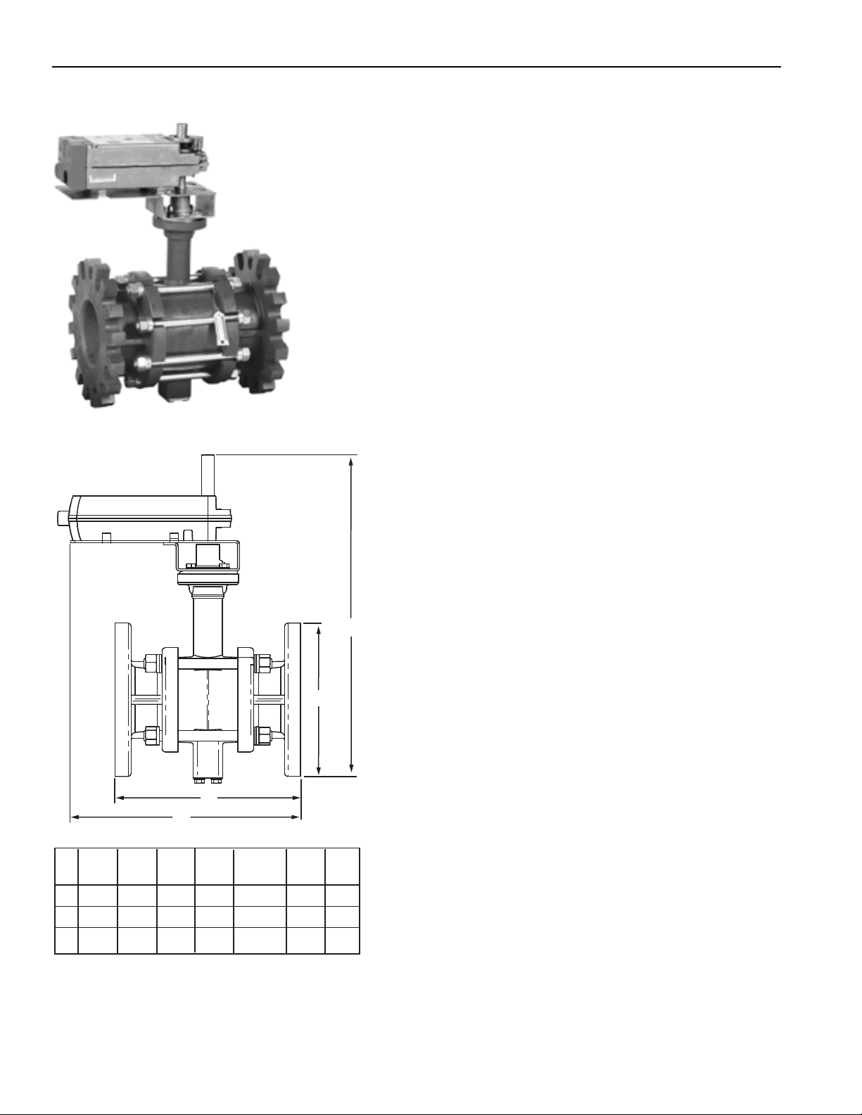
Size

Model

A

B

C

D (depth)

E

Wt.

(in.)

Number

in.

in.

in.

(not shown)

in.

lb


(mm)

(mm)

(mm)

in. (mm)

(mm)

(kg)

4

VBF2J

11

9

13-1/4

9

18-3/4

65


(278)

(229)

(337)

(229)

(476)

(31)

5

VBF2K

12-3/8

10

14-1/4

10

19

75


(352)

(254)

(362)

(254)

(483)

(34)

6

VBF2L

13-7/8

11

15-1/8

11

19-7/8

90


(352)

(278)

(384)

(278)

(505)

(41)


M13732

524

customer.honeywell.com

70-6910

Control Ball Valves

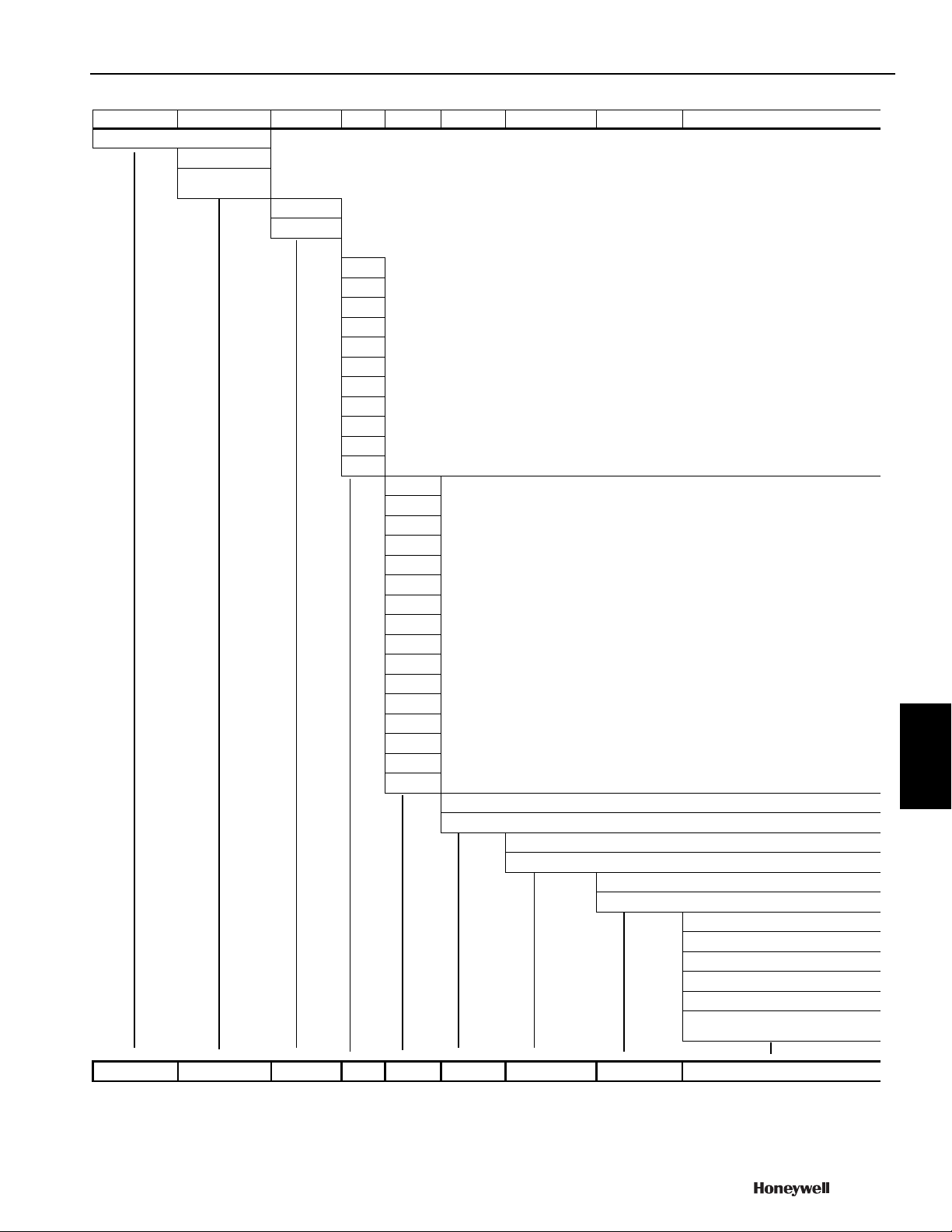
Valve

Fitting

Body/Flow

Size

CV

T/P

Trim

Enclosure

Actuator

VB = valve, ball


F = Flanged


N = Female


NPT threaded


2 = 2 way


3 = 3 way


inch

S.I. metric


A

1/2

DN15


B

3/4

DN20


C

1


DN25


D

1-1/4

DN32


E

1-1/2

DN40


F

2


DN50


G

2-1/2

DN65


H

3


DN80


J

4


DN100


K

5


DN125


L

6


DN150


B

CV Designator (specific values vary by valve size)


C


D


E


F


….


S


T


U


1


2


3


4


5


6


7


1 = ANSI Valve construction


3 = ANSI 300 Valve construction


P = Plated (chrome or nickel)


S = Stainless Steel


0 = no enclosure


R = NEMA 3R enclosure


X = no actuator


A = NSR, Floating, conduit


B = NSR, Modulating


C = SR, 2-Position, 24 Vac


D = SR, Floating/Modulating


F = NSR, Floating, open terminal


strip, 1/2 and 3/4 inch only


VB


F

2


A


B

1


S


0


A


<![if ! IE]>

<![endif]>Commercial

<![if ! IE]>

<![endif]>Components

70-6910


525


Loading...