

Page 1

Place Bar Code Here
V4043, V4044 Valves;
CAUTION
V8043, V8044 Zone Valves
INSTALLATION INSTRUCTIONS
APPLICATION
These valves consist of an actuator motor and valve
assembly for controlling the flow of hot and/or cold water.
The V4043 and V8043 provide two-position, straightthrough control of supply water. The V4044 and V8044
provide two-position, diverting control of supply water.
The valves are designed for use with fan coil and other
units requiring quiet, compact water valves. The V8043E
and F also control supply water for baseboard radiators
and convectors. The V4043E and V8043J provide
straight-through control of steam only. Models are
available with 125 or 300 psi operating pressure.
INSTALLATION
When Installing this Product...
1. Read these instructions carefully. Failure to follow
them could damage the product or cause a hazardous condition.
2. Check the ratings given in the instructions and on
the product to make sure the product is suitable for
your application.
3. Installer must be a trained, experienced service
technician.
4. After installation is complete, check out product
operation as provided in these instructions
1. Disconnect power supply before connecting
wiring to prevent electrical shock of equipment damage.
2. Normally it is not necessary to remove the
powerhead from the valve body during installation. If the valve must be disassembled, be
certain that it is reassembled with the water
IMPORTANT
LOCATION
Install the valve in an area with adequate clearance to:
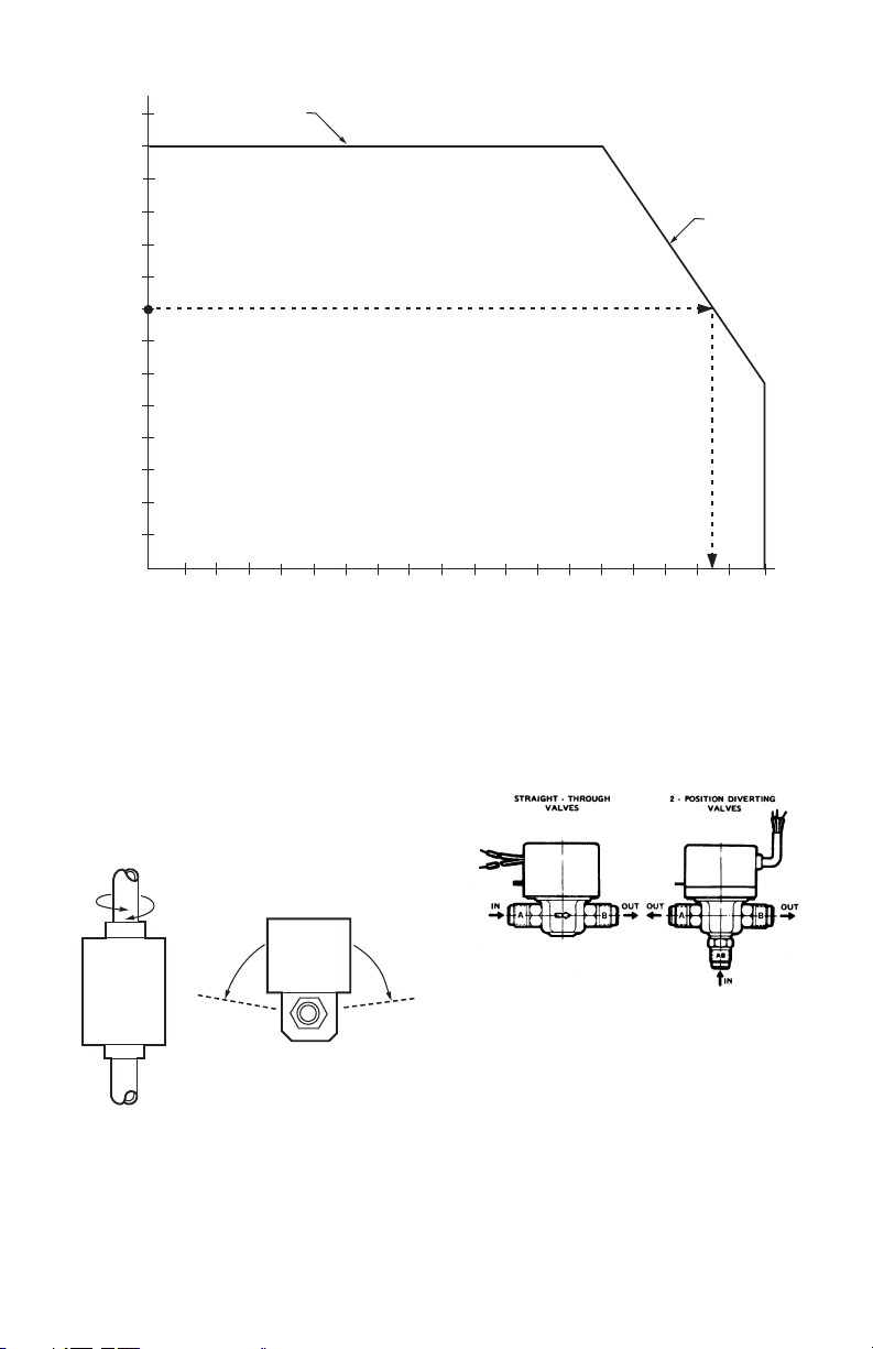
The valve location should be in an area where the
temperature does not exceed the maximum valve
operating temperature as shown in Fig. 1. The maximum
valve operating temperature depends on the maximum
ambient temperature at the valve location and the
maximum fluid temperature. Using the graph in Fig. 1,
the maximum valve operating temperature can be found
as follows:
1. Measure ambient temperature at valve and locate
2. Draw a line from this ambient temperature, parallel
3. Draw a line from this point down to the fluid temp-
flow in the direction of the arrow. Reversal of
the powerhead will result in damage to the
gear train.
3. On 24V systems, never jumper the valve coil
terminals even temporarily. This may burn
out the heat anticipator in the thermostat.
Use this valve in hydronic heating systems
which do not contain dissolved oxygen in the
system water. The dissolved oxygen, which is
found in systems that have a frequent source of
makeup water, causes the rubber plug inside
the valve to deteriorate and eventually fail.
— Move the manual opening lever on the side of the
powerhead.
— Remove the powerhead cover.
— Wire the powerhead.
— Replace the powerhead motor.
this temperature on the ambient temperature scale
on the graph.
with the fluid temperature scale, to the maximum
fluid temperature line.
erature scale to find maximum operating temperature. (Note the example, shown by the dashed line
in Fig. 1).
95-6983-11
Page 2
V4043, V4044 VALVES; V8043, V8044 ZONE VALVES
A
70
(21)
MAXIMUM AMBIENT
TEMPERATURE LINE
EXAMPLE: 150°F (66°C) IS THE AMBIENT TEMPERATURE AT THE VALVE,
235F (113C) IS MAXIMUM FLUID TEMPERATURE.
90
100
80
(32)
(38)
(27)
130
120
110
(54)
(49)
(43)
140
(60)
210
(99)
200
(93)
190
(88)
180
(82)
170
(77)
160
(71)
150
(66)
140
(60)
AMBIENT TEMPERATURE
130
(54)
120
(49)
110
(43)
100
(38)
90
(32)
80
(27)
DEGREES F
DEGREES C
Fig. 1. Maximum temperature characteristics of valves.
MOUNTING
The valve can be mounted in any position on a vertical
line. If the valve is mounted horizontally; the powerhead
must be even with or above the center line of the piping.
Make sure that enough room is provided above the
powerhead to remove the cover for servicing.
MAXIMUM FLUID
TEMPERATURE
LINE
150
160
170
180
190
200
210
220
230
(66)
(71)
(77)
(82)
(88)
(93)
(99)
(104)
FLUID TEMPERATURE
when the valve is de-energized. Refer to the equipment
manufacturer’s instructions to determine which port (A or
B) should be connected to the coil bypass.
(110)
240
(116)
250
(121)
M8164
HORIZONTAL
PIPING
VERTICAL
PIPING
M10162
Fig. 2. Mounting positions.
Mount the valve directly in the tube or pipe. Make sure
that the flow through the valve is in the direction indicated
by the arrow stamped on the valve body.
On diverting valves, the three fittings or ports are labeled
on the bottom of the valve body casting. See Fig. 3. Port
AB is the inlet port and is open at all times. Port A is
closed when the valve is de-energized; port B is open
95-6983—11 2
Fig. 3. Inlet and outlet ports on straight-through and
diverting valves.
FLARE FITTING MODELS
Use new, properly reamed pipe, free from chips. The
valve body is threaded for standard 5/8 in. OD copper, 45
degree SAE flare fitting nuts. These nuts are not furnished
with the valve and must be obtained separately.
SWEAT COPPER MODELS
1. Use new, properly reamed pipe, free from dents or
corrosion.
2. Place the valve onto the pipe. Set the manual opening lever to MAN. OPEN position before applying
heat. This protects the plug inside the valve by
removing it from the seat.
Page 3
V4043, V4044 VALVES; V8043, V8044 ZONE VALVES
3. IMPORTANT: Take care not to burn the plastic portion of the composite adapter plate when soldering.
4. Sweat the joints, keeping the outer surface free
from solder. DO NOT use silver solder because of
the high melting temperature required.
To Install Replacement Powerhead
SYSTEMS WITH OLD STYLE VALVE BODIES (SERIES
1-5)
To install a replacement powerhead in a system with an
old style body (series 1-5), the valve body must be
converted to accept the new powerhead using Part No.
40003918 Conversion Kit. The kit includes a metal plate
with a driveshaft and rubber plug, O-ring, and four screws.
IMPORTANT
Converting the valve body for use with the new
powerhead does not require removal of the valve
body from the pipeline. However, it is necessary
to drain the water from the system before beginning the conversion.
A
MAN
OPEN
AUTO
MANUAL
OPENING
A
LEVER
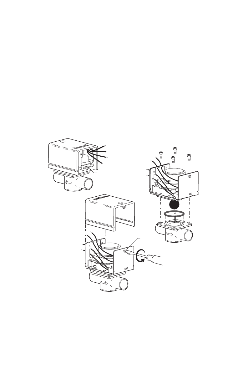
1. Disconnect the power supply before connecting the
wiring to prevent electrical shock or equipment
damage.
2. Disconnect the leadwires to the powerhead at the
terminal block or conduit connection. Remove the
conduit or cable connector if fitted. Label each wire
for rewiring later.
3. Drain the water from the system.
4. Remove the old powerhead from the valve body
(Fig. 4)
a. Place the manual opening lever (normally
closed models only) on the old powerhead in
the MAN. OPEN position (see Fig. 4A).
b. Remove the cover (Fig. 4B).
c. With the cover off, remove the four screws
securing the powerhead to the valve body.
d. Lift the powerhead off the valve body (Fig. 4C).
e. Remove the O-ring from the top of the valve
body.
C
6
V8043F 1051
24V 50/60 CY
.32 AMP @ 60 CY
B
MADE IN CANADA
A
Fig. 4. Remove old powerhead from systems using old style valve bodies
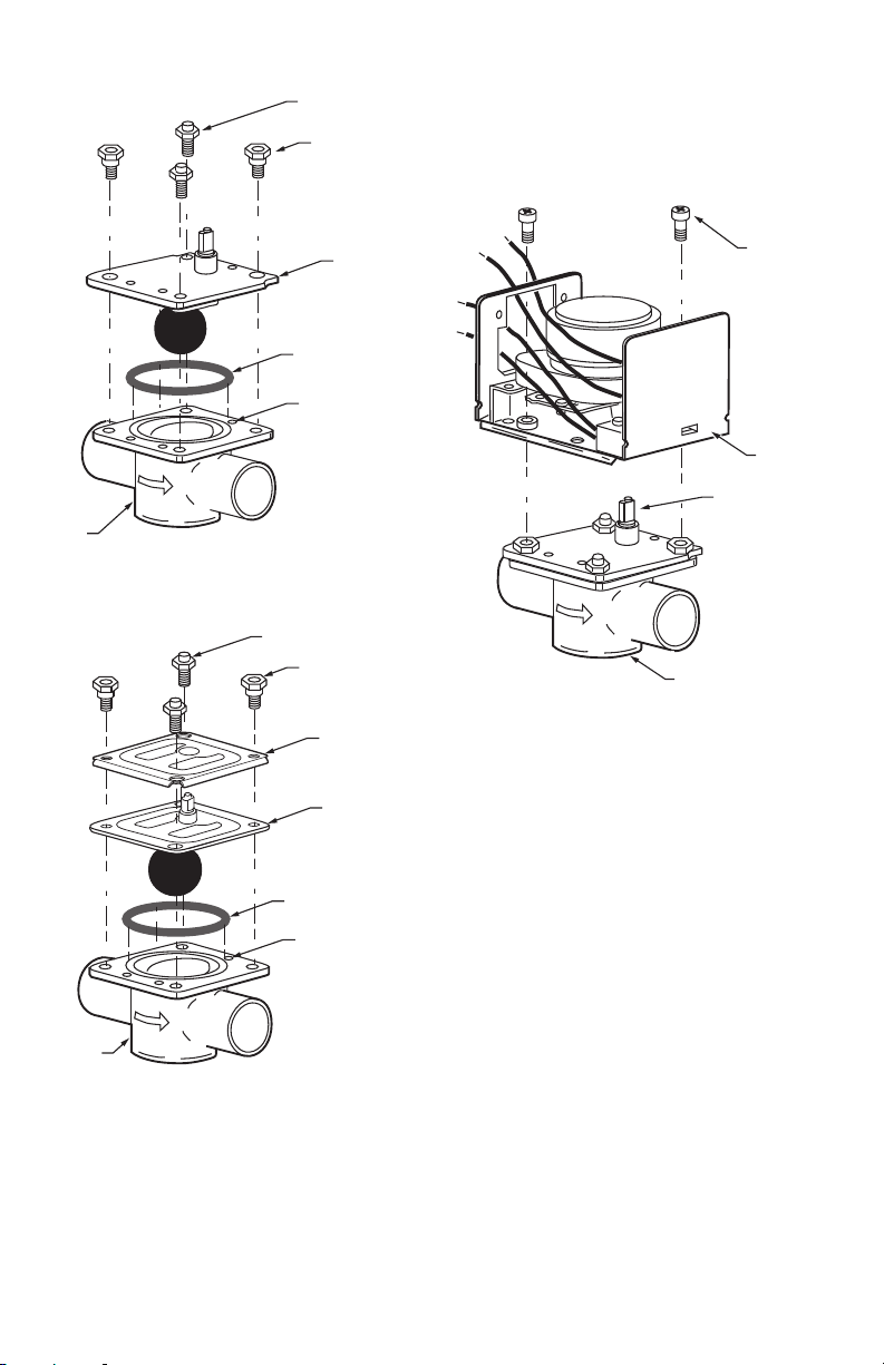
5. Install 40003918 Conversion Kit (Fig. 5)
a. Insert the new O-ring in the valve body.
b. Place metal plate with the rubber plug on top of
the valve body. Make sure the guide pins on the
underside of the metal plate fit into the recesses
on the valve body.
c. Secure the metal plate to the valve body with
the four screws (two sets) provided. One set of
screws has heads with recessed threads to
A
COVER
RETAINING
SCREW
6
V8043F 1051
24V 50/60 CY
.32 AMP @ 60 CY
MADE IN CANADA
B
insert screws for mounting the new powerhead;
insert this set into the larger screw openings.
The other set has domed heads; insert this set
into the smaller screw openings. Each set of
screws must be inserted in opposite corners of
the metal plate so the screws sit flat on the
plate. Make sure the guide pins on the plate fit
into the recesses on the valve body.
3 95-6983—11
B
M10174
Page 4
V4043, V4044 VALVES; V8043, V8044 ZONE VALVES
A
B
V8043F 1036
24V 50/60 CY
.32 AMP @ 60 CY
MADE IN CANADA
6
SECURING
SCREW (2)
REMOVABLE
HEAD
SHAFT
REMOVABLE HEAD
VALVE BODY ASSEMBLY
M10173
HEX-NUT SCREW
WITH DOMED HEADS (2)
HEX-NUT SCREWS
WITH RECESSED
THREADS AND
SHOULDER SHANK (2)
BRASS
ADAPTER
PLATE
O RING
LOCATING
RECESSES (3)
c. Secure the powerhead to the valve body with
the two screws provided.
d. If fitted, reconnect the conduit or cable. Recon-
nect the leadwires at the powerhead.
e. Replace the powerhead cover.
7. Turn on power.
A
VALVE
BODY
Fig. 5a. Install 40003918 conversion kit with brass
A
VALVE
BODY
Fig. 5b. Install conversion kit with composite (steel &
6. Install new powerhead (see Fig. 6)
a. Place the manual opening lever (normally
closed models only) on the new powerhead in
the MAN. OPEN position.
b. Fit the powerhead onto the valve body, ensuring
that the shaft seats correctly. The powerhead
should be aligned so that the manual opening
lever or slot for lever is at the port A end of the
valve body.
B
adapter plate.
HEX-NUT SCREW
WITH DOMED HEADS (2)
O RING
LOCATING
RECESSES (3)
B
plastic) adapter plate.
M32317
HEX-NUT SCREWS
WITH RECESSED
THREADS AND
SHOULDER SHANK (2)
STEEL
PLATE
PLASTIC
PLATE
M32316
Fig. 6. Install new powerhead.
SYSTEMS WITH NEW STYLE VALVE BODIES
(SERIES 6)
IMPORTANT
On a new style valve body that has been converted to accept the new powerhead, it is not
necessary to drain the system if the valve body
remains in the pipeline.
1. Disconnect the power supply before connecting the
wiring to prevent electrical shock or equipment
damage.
2. Disconnect the leadwires to the powerhead at the
terminal block or conduit connection. Remove the
conduit or cable connector, if fitted. Label each wire
for rewiring later.
3. Remove the old powerhead (see Fig. 7):
a. Place the manual opening lever (normally
closed models only) on the old powerhead in
the MAN. OPEN position (Fig. 7A).
b. Remove the screw securing the cover to the
powerhead (Fig. 7B).
c. Lift off the cover from the powerhead.
d. Remove the two screws securing the power-
head to the valve body (Fig. 6).
e. Lift the powerhead off the valve body.
95-6983—11 4
Page 5

Fig. 7. Remove old powerhead cover from systems using new style valve bodies.
A
AUTO
MAN
OPEN
MANUAL
OPENING
LEVER
COVER
RETAINING
SCREW
M10161
A
B
B
V8043F 1036
24V 50/60 CY
.32 AMP @ 60 CY
MADE IN CANADA
6
A
B
4. Install the new powerhead (see Fig. 6):
a. Place the manual opening lever (normally
closed models only) on the new powerhead in
the MAN. OPEN position.
b. Fit the powerhead onto the valve body, ensuring
that the shaft seats correctly. The powerhead
should be aligned so that the manual opening
lever or slot for lever is at the port A end of the
valve body.
c. Secure the powerhead to the valve body with
the two screws provided.
d. If fitted, reconnect the conduit or cable. Recon-
nect the leadwires to the powerhead.
e. Replace the powerhead cover.
5. Turn on the power.
V4043, V4044 VALVES; V8043, V8044 ZONE VALVES
TO
LINE
YELLOW
LEADS
MOTOR
AUXILIARY
SWITCH
THERMOSTAT
(TYPICALLY T87F)
TO CIRCULATOR
OR ANOTHER VALVE
RED LEADS
WIRING
Disconnect the power supply before connecting wiring to
prevent electrical shock or equipment damage.
All wiring must comply with local codes and ordinances.
Connections to the individual valves are shown in Fig. 8-
9. See Fig. 10 through 16 for typical hookups.
If replacing a Taco, Dole, Flair or White Rodgers 3-wire
valve with a 2-wire V8043E or F, see Fig. 17 through 29.
Check that the pressure rating of the new valve is
appropriate for the application.
M5953
Fig. 8. Typical wiring for V8043E, V8044E.
R
THERMOSTAT
(TYPICALLY T87F)
TO CIRCULATOR
OR ANOTHER
VALVE
END SWITCH
1
24V
TRANSFORMER
TH
POWER SUPPLY. PROVIDE DISCONNECT MEANS AND
1
OVERLOAD PROTECTION AS REQUIRED.
TR
TH TR
Fig. 9. Typical wiring for V8043F.
5 95-6983—11
L1
(HOT)
L2
M5952
Page 6

V4043, V4044 VALVES; V8043, V8044 ZONE VALVES
T822 T822 T822
L1
(HOT)
L2
1
POWER SUPPLY. PROVIDE DISCONNECT MEANS AND OVERLOAD
1
PROTECTION AS REQUIRED.
2
CONNECT V8043A BLACK LEADWIRE TO THERMOSTAT.
2
V8043A V8043A V8043A
2 2
M10168
Fig. 10. T822 thermostat, V8043A valve hookup.
T822 T822 T822
L1
(HOT)
L2
1
POWER SUPPLY. PROVIDE DISCONNECT MEANS AND OVERLOAD
1
PROTECTION AS REQUIRED.
2
CONNECT V8043E YELLOW LEADWIRE TO THERMOSTAT.
3
CONNECT V8043E RED LEADWIRES TO L1 (HOT) LINE AND
PRIMARY CONTROL.
Fig. 11. T822, V8043E zone hookup for gas or oil. No
V4044, V8044
VALVE OPERATOR
AQUASTAT® CHANGEOVER CONTROL SWITCHES TO HEATING (RED)
1
AT FLUID TEMPERATURE OF 85F (29C) MAX TO COOLING (BLUE) AT
FLUID TEMPERATURE OF 60F (18C) MIN.
Fig. 12. Wiring diagram for V4044 and V8044 with
Aquastat changeover control.
2
V8043E V8043E V8043E
3 3 3
domestic hot water.
1
MOTOR
2 2
L4006A
CIRCULATOR
HEATING
COOLING
THERMOSTAT
RED
BLUE
YELLOW
HIGH
LIMIT
TO OIL PRIMARY
CONTROL OR TO
TRANSFORMER
AND LOW VOLTAGE
GAS VALVE
M10169
TO
POWER
M10171
T822 T822 T822
L1
(HOT)
L2
1
POWER SUPPLY. PROVIDE DISCONNECT MEANS AND OVERLOAD
1
PROTECTION AS REQUIRED.
2
CONNECT V8043E YELLOW LEADWIRE TO THERMOSTAT.
3
CONNECT V8043E RED LEADWIRES TO AQUASTAT®.
Fig. 13. T822, V8043E zone hookup for gas or oil with
or without domestic hot water. Without domestic hot
water, use L8148J for gas, L8148A for oil. With
domestic hot water, use L8124E for gas, L8124A or C
ZONE 1
V8043F
END SWITCH
TH-TR
TH
TR
TZ
TV
C1
C2
TO
CIRCULATOR
Fig. 14. Typical 3-zone system. Use an AT87A
transformer to power up to 5 more zone valves.
2
V8043E V8043E V8043E
3 3 3
TT
1
2C1
C2
CIRCULATOR
for oil.
T87F
END SWITCH END SWITCH
TH-TR
L8124G
ZONE 2 ZONE 3
V8043F V8043F
TH
TR
L1
2
(HOT)
1
L2
B1
B2
TO BURNER
CIRCUIT
2 2
B1
TO BURNER
CONTROL
CIRCUIT
B2
M10170
T87F T87F
ADD
JUMPER
TO EACH
TH
120 V
POWER
SUPPLY
VALV E
TR
M5954
TH-TR
95-6983—11 6
Page 7

V4043, V4044 VALVES; V8043, V8044 ZONE VALVES
L1
(HOT)
L2
1
C
A
B
D
THERMOSTAT
V8043E
TO
AUXILIARY
CIRCUITS
1
POWER SUPPLY. PROVIDE DISCONNECT MEANS
AND OVERLOAD PROTECTION AS REQUIRED.
M10163
YELLOW
YELLOW
RED
RED
E
CONNECTIONS FOR V8043E
TO
CIRCULATOR
CONTROL
CIRCUIT
(LEADWIRE MODEL)
TH-TR TH
ZONE 1
INTEGRAL
TRANSFORMER
W775A PANEL
ZONE 1
END SWITCH
V8043F
ZONE 2
END SWITCH
V8043F
TH-TR TH
TR
B
B
R
W
BR
T87F
TR
ZONE 2
T87F
ZONE 3
END SWITCH
V8043F
TH-TR TH
TR
ZONE 3
B
B
R
W
BR
W
BR
T87F
ZONE 4
END SWITCH
V8043F
TH-TR TH
TR
ZONE 4
B
B
R
B
B
R
W
BR
T87F
M5980
ZONE V8043E
RED
RED
YELLOW
YELLOW
W775A PANEL
RED
RED
YELLOW
POWER
SUPPLY
YELLOW
B
B
R
W
BR
L1
(HOT)
L2
Fig. 15. Typical 4-zone system. Use an additional W775A to power up to 4 more zone valves.
TO BURNER
AND / OR
ZONE 1
ZONE 2
T87F
T87F T87F T87F T87F
ZONE 3
ZONE 4
ZONE 5
CIRCULATOR
CIRCUIT
V8043F
END SWITCH
TH-TR
TH
TR
NOTE: IF CODE PERMITS, V8043E AND V8043F CAN BE USED INTERCHANGEABLY WHEN WIRED AS SHOWN.
V8043F
END SWITCH
TH-TR
Fig. 16. Typical 5-zone system. Use an AT87A transformer to power up to 5 more zone valves.
How to Replace a Taco 3-Wire Valve with
a Honeywell 2-Wire Valve
A
TO AUXILIARY
CIRCUITS
THERMOSTAT
19.)
B
C
D
E
1
L1
(HOT)
L2
POWER SUPPLY. PROVIDE DISCONNECT MEANS
1
AND OVERLOAD PROTECTION AS REQUIRED.
Fig. 17. Existing Taco System. (Wires are identified by
letters for easy correspondence to wires on Figs. 18 &
TH
TR
AT87A
TRANSFORMER
TACO VALVE
1
2
3
M5958
V8043F
END SWITCH
TH-TR
TH
TR
L1
(HOT)
L2
1
Fig. 18. Wiring a Honeywell V8043E to a Taco System.
(Wires are identified by letters for easy
V8043E V8043E
YELLOW
YELLOW
RED
RED
POWER SUPPLY. PROVIDE DISCONNECT MEANS AND
1
OVERLOAD PROTECTION AS REQUIRED.
YELLOW
YELLOW
RED
RED
M10164
correspondence to wires on Fig. 17.)
7 95-6983—11
Page 8

V4043, V4044 VALVES; V8043, V8044 ZONE VALVES
V8043F
END SWITCH
1
L1
(HOT)
L2
L1
(HOT)
L2
Fig. 19. Wiring a Honeywell V8043F to a Taco System
(2 options). (Wires are identified by letters for easy
correspondence to wires on Fig. 17.)
C
TH-TR
A
THERMOSTAT
V8043F
END SWITCH
1
C
TH-TR
A
THERMOSTAT
1
POWER SUPPLY. PROVIDE DISCONNECT MEANS AND
OVERLOAD PROTECTION AS REQUIRED.
D
TO
AUXILIARY
E
CIRCUITS
TH
TR
B
D
TO
E
AUXILIARY
CIRCUITS
TH
TR
B
M5960
How to Replace a Dole 3-Wire Valve with
a Honeywell 2-Wire Valve
DOLE VALVE
C
B
THERMOSTAT
B
THERMOSTAT
A
D
22.)
A
C
E
F
1
L1
(HOT)
L2
POWER SUPPLY. PROVIDE DISCONNECT MEANS
1
AND OVERLOAD PROTECTION AS REQUIRED.
Fig. 20. Existing Dole System. (Wires are identified by
letters for easy correspondence to wires on Figs. 21 &
1
L1
(HOT)
L2
TO TERMINALS
T, T ON
BURNER RELAY
POWER SUPPLY. PROVIDE DISCONNECT MEANS
1
AND OVERLOAD PROTECTION AS REQUIRED.
Fig. 21. Wiring a Honeywell V8043E to a Dole System.
(Wires are identified by letters for easy
correspondence to wires on Fig. 20.)
D
3
1
F
TO TERMINALS
T, T ON
BURNER RELAY
V8043E
YELLOW
YELLOW
RED
RED
2
4
E
M5977
M5965
V8043F
A
B
TH-TR
C
THERMOSTAT
A
B
TH-TR
C
THERMOSTAT
END SWITCH
END SWITCH
1
L1
(HOT)
L2
1
L1
(HOT)
L2
1
POWER SUPPLY. PROVIDE DISCONNECT MEANS AND
OVERLOAD PROTECTION AS REQUIRED.
Fig. 22. Wiring a Honeywell V8043F to a Dole system
(2 options). (Wires are identified by letters for easy
correspondence to wires on Fig. 20.)
V8043F
F
TO TERMINALS
E
T, T ON
BURNER RELAY
TH
TR
D
F
TO TERMINALS
E
T, T ON
BURNER RELAY
TH
TR
D
M5966
How to Replace a Flair 3-Wire Valve with
a Honeywell 2-Wire Valve
FLAIR VALVE
1
L1
(HOT)
L2
Fig. 23. Existing Flair System. (Wires are identified by
letters for easy correspondence to wires on Figs. 23 &
L1
(HOT)
L2
POWER SUPPLY. PROVIDE DISCONNECT MEANS
1
AND OVERLOAD PROTECTION AS REQUIRED.
Fig. 24. Wiring a Honeywell V8043E to a Flair System.
(Wires are identified by letters for easy
correspondence to wires on Fig. 23.)
A
1
B
C
B
THERMOSTAT
TO TERMINALS
T, T ON
BURNER RELAY
THERMOSTAT
C
1
POWER SUPPLY. PROVIDE DISCONNECT MEANS AND
OVERLOAD PROTECTION AS REQUIRED.
1
3
2
4
A
24.)
E
TO TERMINALS
T, T ON
F
BURNER RELAY
5
D
M5978
V8043E
YELLOW
D
YELLOW
E
F
RED
RED
M5965
95-6983—11 8
Page 9

V4043, V4044 VALVES; V8043, V8044 ZONE VALVES
V8043F
END SWITCH
1
L1
(HOT)
L2
L1
(HOT)
L2
1
Fig. 25. Wiring a Honeywell V8043F to a Flair System
(2 options). (Wires are identified by letters for easy
A
B
TH-TR
C
THERMOSTAT
V8043F
END SWITCH
1
A
B
TH-TR
C
THERMOSTAT
POWER SUPPLY. PROVIDE DISCONNECT MEANS AND
OVERLOAD PROTECTION AS REQUIRED.
correspondence to wires on Fig. 23.)
F
TO TERMINALS
E
T, T ON
BURNER RELAY
TH
TR
D
F
TO TERMINALS
E
T, T ON
BURNER RELAY
TH
TR
D
M5966
How to Replace a White-Rodgers 3-Wire
Valve with a Honeywell 2-Wire Valve
WHITE-RODGERS
WATE R VALVE
THERMOSTAT
56
4
1
POWER SUPPLY. PROVIDE DISCONNECT MEANS AND OVERLOAD
PROTECTION AS REQUIRED.
1311 OR 1321
VALVE
6
4
5
Fig. 26. Existing White-Rodgers System.
1
L1
(HOT)
L2
5
3
THERMOSTAT
TO
AUXILIARY
1
CIRCUIT
L1
(HOT)
L2
POWER SUPPLY. PROVIDE DISCONNECT MEANS AND
1
OVERLOAD PROTECTION AS REQUIRED.
IF TRANSFORMER SUPPLIES POWER TO AUXILIARY CIRCUIT,
2
WIRE AUXILIARY CIRCUIT AS SHOWN IN LOWER DIAGRAM.
TAPE UNUSED END AND TUCK INTO HOLE.
3
Fig. 27. Wiring a Honeywell V8043E to a White-
Rodgers System.
3
2
1
6
4
TO 6 ON
THERMOSTAT
TO AUXILIARY
CIRCUIT
TO AUXILIARY
CIRCUIT
YELLOW
RED
YELLOW
YELLOW
RED
RED
RED
1
L1
(HOT)
L2
M5711
2
M5712
V8043F
2
L1
(HOT)
1
L2
TO AUXILIARY
CIRCUITS
END SWITCH
TR
TH
TH-TR
6
5
4
3
THERMOSTAT
TO AUXILIARY
2
CIRCUITS
L1
(HOT)
1
L2
1
POWER SUPPLY. PROVIDE DISCONNECT MEANS AND
OVERLOAD PROTECTION AS REQUIRED.
2
IF TRANSFORMER SUPPLIES POWER TO AUXILIARY CIRCUIT,
WIRE AUXILIARY CIRCUIT AS SHOWN IN LOWER DIAGRAM.
3
TAPE UNUSED END AND TUCK INTO HOLE.
Fig. 28. Wiring a Honeywell V8043F to a White-
Rodgers System (one option).
END SWITCH
TH-TR
TR
TH
M5713
V8043F
TO
2
AUXILIARY
CIRCUIT
L1
(HOT)
1
L2
END SWITCH
TH TR
TH-TR
6
5
4
3
THERMOSTAT
TO
AUXILIARY
2
CIRCUIT
L1
(HOT)
1
L2
POWER SUPPLY. PROVIDE DISCONNECT MEANS AND
1
OVERLOAD PROTECTION AS REQUIRED.
IF TRANSFORMER SUPPLIES POWER TO AUXILIARY CIRCUIT,
2
WIRE AUXILIARY CIRCUIT AS SHOWN IN LOWER DIAGRAM.
TAPE UNUSED END AND TUCK INTO HOLE.
3
Fig. 29. Wiring a Honeywell V8043F to a White-
Rodgers System (alternate option).
END SWITCH
M5714
9 95-6983—11
Page 10

V4043, V4044 VALVES; V8043, V8044 ZONE VALVES
CAUTION
OPERATION AND CHECKOUT
On 24 V systems, never jumper the valve coil
terminals even temporarily. This may burn out
the heat anticipator in the thermostat.
NORMALLY CLOSED MODELS
With the manual opener set to AUTO and the powerhead
energized, the valve is opened as shown in Fig. 30A.
When the powerhead is de-energized, a spring-return
mechanism drives the valve to the closed position as
shown in Fig. 30B. The valve can also be opened with no
electrical power by moving the manual opening lever over
the stop and pushing slowly and firmly to the MAN. OPEN
position. The stop permits the valve to be locked in the
open position. The valve will return to the automatic
position when the valve is energized.
Auxiliary switch is not energized when the valve is
manually opened.
NORMALLY OPEN MODELS
When the powerhead is de-energized, a spring-return
mechanism drives the valve to the open position (Fig.
30A). When energized, the valve is closed as shown in
Fig. 30B. A reverse-acting thermostat is required to
control a normally open valve.
NOTE: Inlet Port is stamped “A”, Outlet Port is stamped
“B” on the valve body.
Checkout
1. Raise the setpoint on the zone thermostat above
the room temperature to initiate a call for heat.
2. Observe all control devices—the valve should open
and the auxiliary switch should make the circuit to
the circulator or other valve at the end of the opening stroke.
3. Lower the setpoint on the zone thermostat below
the room temperature.
4. Observe the control devices. The valve should
close and the auxiliary equipment should stop.
Service
This valve should be serviced by a trained, experienced
service technician.
1. If the valve is leaking, drain the system and check
to see if the O-ring needs replacing.
2. If the gear train is damaged, replace the entire powerhead assembly. See the Installation section. If the
motor is burned out, replace the motor. See
Replacement Parts list in the TRADELINE® Catalog.
NOTE: Honeywell zone valves are designed and tested
for silent operation in properly designed and
installed systems. However, water noises may
occur as a result of excessive water velocity or
piping noises may occur in high temperature
(over 212° F [100° C]) systems with insufficient
water pressure.
NOTE: These hydronic valves are not suitable for use in
open loop systems where there is air exposure.
B
OUT
A
IN
CLOSED POSITION
B
OUT
B
M5951
A
IN
OPEN POSITION
A
Fig. 30. V8043 operation for normally closed valve.
95-6983—11 10
Page 11

V4043, V4044 VALVES; V8043, V8044 ZONE VALVES
11 95-6983—11
Page 12

V4043, V4044 VALVES; V8043, V8044 ZONE VALVES
Automation and Control Solutions
Honeywell International Inc.
1985 Douglas Drive North
Golden Valley, MN 55422
customer.honeywell.com
® U.S. Registered Trademark
© 2010 Honeywell International In c.
95-6983—11 T.D. Rev. 09-10
Printed in U.S.A.
 Loading...