

Page 1
62-0202-02
V5852A, V5853A, V5862A,
WARNING
CAUTION
M19619C
INLET
OUTLET
PORT A
PORT AB
PORT B
V5863 FLOWV5862A3 FLOW
1 (25)
1-1/4 (32)
1-1/2 (38)
4-1/8 (105)
4-15/16 (125)
5-1/8 (130)
1-5/8 (41)
2 (50)
2-3/16 (55)
2-1/16 (53)
2-7/16 (62)
2-9/16 (65)
3-5/8 (92)
3-5/8 (92)
3-7/8 (98)
BCDE
2-5/16 (58)
2-5/16 (58)
2-11/16 (69)
G
2 (50)
2-3/16 (55)
2-9/16 (65)
F
VALVE SIZE
A (mm)
E
A
C
C
F
B
D
23/32
(18)
G
1/4 (6)
STROKE
MINIMUM CLEARANCE
9-7/8
(250)
FLOW DIAGRAM
FOR 1, 1-1/4 AND 1-1/2 INCH VALVES
V5863A Cartridge Globe Valves
INSTALLATION INSTRUCTIONS
INSTALLATION
When Installing this Product...
1. Read these instructions carefully. Failure to follow
them could damage the product or cause a
hazardous condition.
2. Check ratings given in instructions and on the
product to ensure the product is suitable for your
application.
3. Installer must be a trained, experienced service
technician.
4. After installation is complete, check out product
operation as provided in these instructions.
5. Do not use Series 3000 actuators on 1/2 in. or
3/4 in. valves.
Severe Scalding Hazard.
Contact with hot liquid can lead to severe
injury or cause death.
For a pressurized valve, only open with Valve
Cartridge Replacement Tool. For complete safety,
release system pressure to the valve body before
changing cartridge.
IMPORTANT
Mount all 1/2 in. and 3/4 in. valves in return flow.
When delta p-values exceed 8.70 psi (60 kPa),
noise can develop.
Mounting
The valve body should be completely installed in the pipe
line before the actuator is installed.
IMPORTANT
The insert is packed separately from the 1/2 in.
and 3/4 in. V5852, V5853 Sweat Valves. The
valve must be installed and soldered before
installing the insert in the valve. Torque insert
between 27 and 44 in.-lb.
1. Verify pipe size and flow direction for the valve
being used.
2. Position the valve for easy actuator installation.
3. Install the valve using the applicable tools and
supplies (wrenches, solder, flux, torch or soldering
iron). Follow standard practices.
Sweat Valve Damage Hazard.
Soldering the valve with the cartridge in place
can damage the device.
Prior to attaching valve to piping, remove
cartridge from potential exposure to heat.
IMPORTANT
• Before installing the valve, use the protective
cover/manual handle to ensure the valve stem
operates freely. Impaired stem operation can
indicate a bent stem (due to rough handling).
This condition can require replacing the valve.
• When installing valves, make sure the flow
direction is correct by checking the arrow on the
valve body.
• Mount the valve only with the stem pointing
upward.
• Leave the protective cover in place until ready to
attach the actuator.
Location
Select a location where the valve and actuator are
accessible.
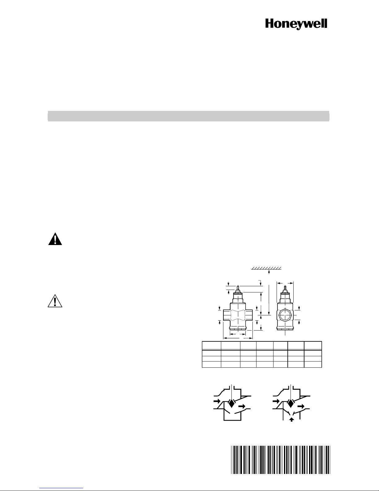
Fig. 1. Dimensions of Series 3000 V5862A and
V5863A Valves in in. (mm).
Page 2
V5852A, V5853A, V5862A, V5863A CARTRIDGE GLOBE VALVES
V5852/V5862
B
V5853/V5863
B
1/4
STROKE
(7)
A
1/4
STROKE
(7)
B
A
23/32
(18)
B
23/32
(18)
B
1-3/16 (30)
C
1-3/16 (30)
D
C
FLOW DIAGRAM
INLET
D
FLOW DIAGRAM
PORT A
E
PORT B
OUTLET
PORT AB
VALVE
SIZE
1/2 (13)
3/4 (19)
2-1/3 (60)
3-2/9 (82)
B
A
(NPT)
1/2 NPT
3/4 NPT
C
1-1/3 (34)
1-1/4 (32)
(NPT)
1/2 NPT
3/4 NPT
V5853 (SWEAT)
VALVE
SIZE
1/2 (13)
3/4 (19)
2-1/2 (63)
3-2/9 (82)
B
A
NPT
5/6 (21)
1 (27)
C
1-1/6 (30)
1-4/7 (40)
1-1/3 (34)
1-2/7 (33)
V5863 (NPT)
VALVE
SIZE
1/2 (13)
2-5/7 (69)
3/4 (19)
3-2/9 (82)
NOTE: SOLDER ENDS CONFORM TO ANSI B16-18.
B
A
NPT
1/2 NPT
3/4 NPT
C
1-1/4 (32)
1-3/5 (41)
D
1-1/3 (34)
1-2/7 (33)
D
D
(SWEAT)
5/8 (16)
7/8 (22)
(SWEAT)
5/8 (16)
7/8 (22)
E
(NPT)
1/2 NPT
3/4 NPT
E
M34543
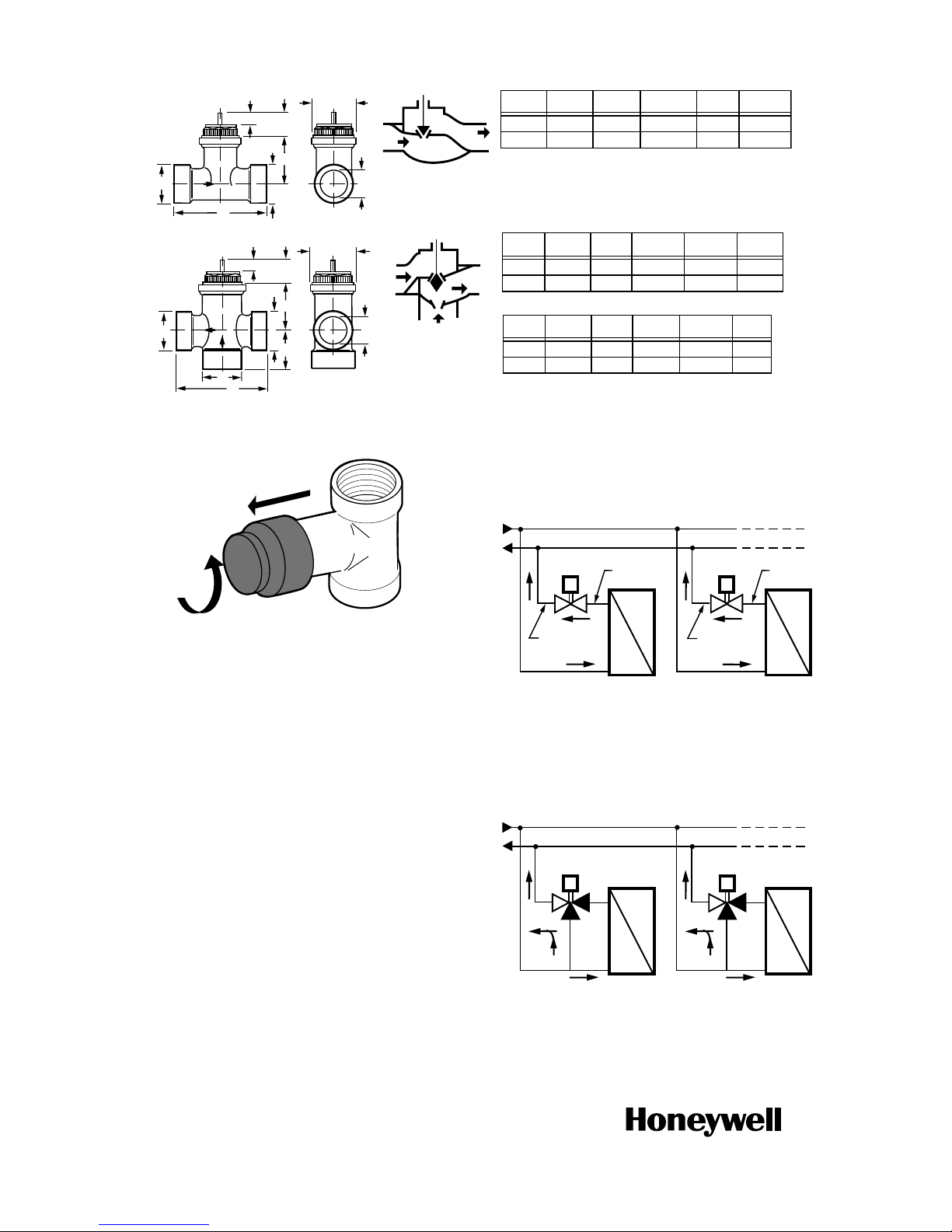
D
Fig. 2. Dimensions of Series 1000 and 2000 V5852A, V5853A, V5862A and V5863A Valves in in. (mm).
Two-Way Valve Flow
In the two-way valves, the direction of flow is always from
inlet port to outlet port as indicated by the arrows on the
valve body (see Fig. 4).
M8228A
Fig. 3. Removing protective cover from valve.
OPERATION
The valves are supplied with a threaded plastic protective
cover/manual handle to protect the stem and to allow for
manual operation. Use the protective cover/manual
handle to fill the system during initial installation.
Turning the protective cover/manual handle:
— Clockwise: pushes the center stem of the valve down,
compressing the valve spring and closing the valve.
— Counterclockwise: allows the spring to expand,
pushing the center stem up and opening the valve.
NOTES:
— You can also use the protective cover/handle
for heating/cooling with neither a controller
nor actuator during building construction.
— Retain the protective cover. It can be needed
for future manual operation.
By using this Honeywell literature, you agree that Honeywell will have no liability for any
damages arising out of your use or modification to, the literature. You will defend and
indemnify Honeywell, its affiliates and subsidiaries, from and against any liability, cost, or
damages, including attorneys’ fees, arising out of, or resulting from, any modification to the
literature by you.
Automation and Control Solutions
Honeywell International Inc.
1985 Douglas Drive North
Golden Valley, MN 55422
customer.honeywell.com
® U.S. Registered Trademark
© 2013 Honeywell International Inc.
62-0202—02 M.S. Rev. 02-13
Printed in United States
INLET
M5357A
+
–
OUTLET
INLET
+
–
OUTLET
Fig. 4. Two-way valve operation block diagram.
Three-Way Valve Flow
Three-way valves are designed as mixing valves. This
means that port AB is total flow outlet; port A is controlled
flow inlet; and port B is bypass inlet (see Fig. 5).
AB
A
B
+
– AB
A
B
Fig. 5. Three-way valve operation block diagram.
M5358
+
–
 Loading...