

Page 1
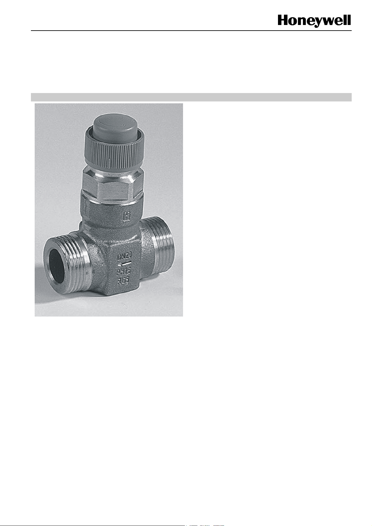
V5825B
Small Linear Valve / PN25
DH Compact Valve
PRODUCT DATA
FEATURES
• Pressure-balanced kvs 1.0...10 m3/hr
• Normally-closed valve
• Supplied with manual adjustment cap for start-up
• Small size
• Threaded and welding connection sets
• Bronze body, stainless steel trim
• Low seat leakage rate
• Metal-to-metal seating for long life span
GENERAL
Single-seated 2-way valves for modulating control of hot /
chilled water in heating, ventilating, and air conditioning
systems.
These valves are designed especially for flow control in
hydraulic systems with high temperatures and pressures,
such as district heating systems. It can also be used in
combination with M6410/M7410 (300 N) actuators as well as
with ML7430/35 and ML6435 (400 N) actuators.
• Easy mounting of direct-coupled electric actuators
• Approval per DIN EN 14597
SPECIFICATIONS
Action valve is closed by its spring
Nominal pressure rating PN25
Rangeability 50:1
Leakage rate: max. 0.05% of k
Characteristic split characteristic / linear - equal
percentage
Stroke 6.5 mm
Close-off pressure 0...1600 kPa with 300 N actuator
Valve body
End connections
Material
Trim
Seat
Plug
Stem
Packing EPDM, O-ring
Medium water; glycol/water mixture
Medium temperature 2...130 °C
Dimensions See Fig. 2 on page 4
0...2500 kPa with 400 N actuator
external thread per ISO 228/1
red bronze (DIN 1705)
stainless steel (W.-No. 1.4305)
stainless steel (W.-No. 1.4305)
stainless steel (W.-No. 1.4305)
(max. 50% glycol per VDI 2035)
VS
Copyright © 2009 Honeywell Inc. • All rights reserved EN0B-0403GE51 R0709
Page 2
V5825B SMALL LINEAR VALVE / PN25
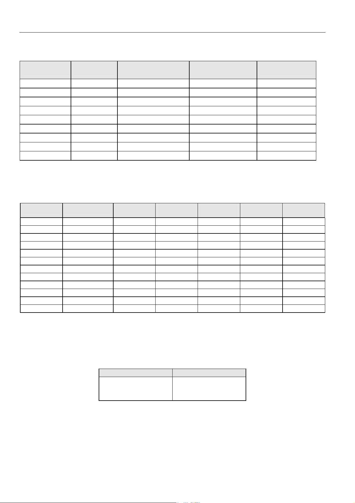
SIZES AND FLOW CAPACITIES
size kVS (m3/h)
DN15 0.25 1600 2500 V5825B1001
DN15 0.40 1600 2500 V5825B1019
DN15 0.63 1600 2500 V5825B1027
DN15 1.0 1600 2500 V5825B1035
DN15 1.6 1600 2500 V5825B1043
DN20 2.5 1600 2500 V5825B1050
DN20 4.0 1600 2500 V5825B1068
DN25 6.3 1600 2500 V5825B1076
DN32 10.0 1600 2500 V5825B1084
close-off pressure (kPa)
with 300 N actuator
close-off pressure (kPa)
with 400 N actuator
order number
ACTUATORS
Suitable electric actuators:
OS no. data sheet
M7410C1015 EN0B-0096GE02 24 Vac - valve cap 300 -
M6410C2031 EN0B-0096GE02 24 Vac - integrated 300 -
M6410C4037 EN0B-0096GE02 24 Vac 2 integrated 300 -
M6410L2031 EN0B-0096GE02 230 Vac - integrated 300 -
M6410L4037 EN0B-0096GE02 230 Vac 2 integrated 300 -
M7410E1028 EN0B-0097GE02 0/2...10 V - valve cap 300 -
M7410E2034 EN0B-0097GE02 0/2...10 V - integrated 300 -
M7410E4030 EN0B-0097GE02 0/2...10 V 2 integrated 300 -
ML6435B1008 EN0B-0259GE51 24 Vac - valve cap 400 stem retract
ML6435B1016 EN0B-0259GE51 230 Vac - valve cap 400 stem retract
ML7430E1005 EN0B-0260GE51 0/2...10 V - integrated 400 -
ML7435E1004 EN0B-0260GE51 0/2...10 V - valve cap 400 stem retract
For further technical information about electric actuators, please consult Honeywell Product Data Sheets.
control
signal
auxiliary
switches
manual
adjustment
stem force
(N)
power failure
position
APPROVAL
NOTE: For V5825B valves in combination with the following actuators, approval according to DIN EN 14597.
Actuator O.S. no. DIN registration no.
ML6435B1008
ML6435B1016
ML7435E1004
EN0B-0403GE51 R0709 2
1F152/08
Page 3

V5825B SMALL LINEAR VALVE / PN25
OPERATION
DH Compact valves V5825B are available in four sizes, from
DN15 through DN32. This description refers to size DN25.
A built-in return spring (4) produces the closing force on the
port A to port B. The valve is supplied with a screwed-on
valve cap for manual operation and for protection of the
1
4
5
2
3
6
AB
1 valve insert
2 valve body
3 valve plug
Fig. 1. DH Compact Valve V5825B, size DN25
(cross-sectional drawing)
4 return spring
5 cone stem boring
6 compensation chamber
system. This allows the system to be filled and set up for the
initial heating / cooling during the building construction phase
without the use of a controller or actuator.
The medium flows through the valve from port A to port B, in
the direction of the arrow mark on the valve body.
The flow rate is limited by the setting of the valve plug (3),
which is positioned either using the manually adjustable valve
cap or by an actuator. Maximum stroke means maximum flow
rate.
In order to be able to close precisely against high pressure
differences, the valve compensates pressure differences by
means of a cone stem boring (5) connecting to a compensation chamber (6).
Some specific actuators automatically retract the stem in the
event of a power failure in order to close the valve and stop
the flow of medium (refer to section "Actuators" on page 2).
INSTALLATION
When installing the valve, ensure that the flow direction
corresponds with the arrow direction on the valve body (see
Installation Instructions MU1B-0224GE51).
• The valve must not be mounted with the stem pointing
below the horizontal.
• The valve should be installed stress-free.
External threaded or welding connection sets are available
(refer to section "Accessories" on page 5).
• The installation of a strainer is strongly recommended; in
district heating systems, it is obligatory.
• Make sure that water hammers are avoided.
• For pressure test, the valve (with actuator) must be open.
• The adjustment cap must be removed from the valve only
when an actuator is fitted.
• The water must not contain more than 50% glycol
according to VDI 2035 requirements.
MAINTENANCE
In case of leakage or heavy soiling of the valve, the complete
valve insert (1) can be replaced (see section "Spare Parts" on
page 6).
EN0B-0403GE51 R0709
3
Page 4

V5825B SMALL LINEAR VALVE / PN25
DIMENSIONS
Valve V5825B
valve
normally
closed
max. 6.5
18
11. 5
fmax
c
g
d
e
Fig. 2. V5825B Dimensions (mm)
threaded connection welding connectionDN a
b
b* a2 b* a1
15 G¾" 65 125 R½" 175
20 G1" 70 138 R¾" 184
25 G1¼" 75 154 R1" 180
32 G1½" 100 192 R1¼" 264
a
dimensions in mm
16∅
20∅
27∅
32∅
a2
a1
b
b*
c d e f g
59 18 35 77 270
67 18 36 85 280
69 23 46 87 280
89 25 57 107 300
EN0B-0403GE51 R0709
4
Page 5

V5825B SMALL LINEAR VALVE / PN25
ACCESSORIES
Connection Sets
For threaded connections according to ISO 7/1 for steel pipes or malleable iron, refer to Fig. 3 (ACS-...T) or Fig. 4 (ACS-...W).
a
Fig. 3. External threaded connection
Two connection sets are necessary
connection pipe size DN order no. connection set description a b c
external
thread
welding
R½"
R¾"
R1"
R1¼"
½"
¾"
1"
1¼"
15
20
25
32
15
20
25
32
b
ACS-15T
ACS-20T
ACS-25T
ACS-32T
ACS-15W
ACS-20W
ACS-25W
ACS-32W
a c
Fig. 4. Welding connection
threaded connection
(consisting of 1 union nut,
1 tailpiece, and 1 gasket)
welding connection
(consisting of 1 union nut,
1 tailpiece, and 1 gasket)
G¾"
G1"
G1¼"
G1½"
G¾"
G1"
G1¼"
G1½"
R½"
R¾"
R1"
R1¼"
-
-
-
-
-
-
-
-
16∅
20∅
27∅
32∅
EN0B-0403GE51 R0709
5
Page 6

V5825B SMALL LINEAR VALVE / PN25
SPARE PARTS
Table 1. Valve inserts
kvs order no.
0.25 0903809
0.40 0903810
0.63 0903811
1.0 0903812
1.6 0903813
2.5 0903814
4.0 0903815
6.3 0903816
10.0 0903817
Table 2. Adapter for Salina
valve type to
be replaced
V5872B1003 V5825B1001 0.25 AK15-15
V5872B1011 V5825B1019 0.40 AK15-15
V5872B1029 V5825B1027 0.63 AK15-15
V5872B1037 V5825B1035 1.0 AK15-15
V5872B1045 V5825B1043 1.6 AK15-15
V5872B1052 V5825B1050 2.5 AK20-15
V5872B1060 V5825B1068 4.0 AK20-25
V5872B1078 V5825B1076 6.3 AK25-25
V5872B1086 V5825B1084 10.0 n.a.
NOTE: The valve adapter kit contains all of the components
required to replace one V5872B valve with the
V5825B.
new valve
model
kvs
order no. of valve
adapter kit
Fig. 5. Typical valve insert
Fig. 6. Valve adapter
Manufactured for and on behalf of the Environmental and Combustion Controls Division of Honeywell Technologies Sàrl, Rolle, Z.A. La Pièce 16, Switzerland by its Authorized Representative:
Automation and Control Solutions
Honeywell GmbH
Böblinger Strasse 17
71101 Schönaich
Germany
Phone: (49) 7031 63701
Fax: (49) 7031 637493
http://ecc.emea.honeywell.com
Subject to change without notice. Printed in Germany
EN0B-0403GE51 R0709
 Loading...