

Page 1
GENERAL
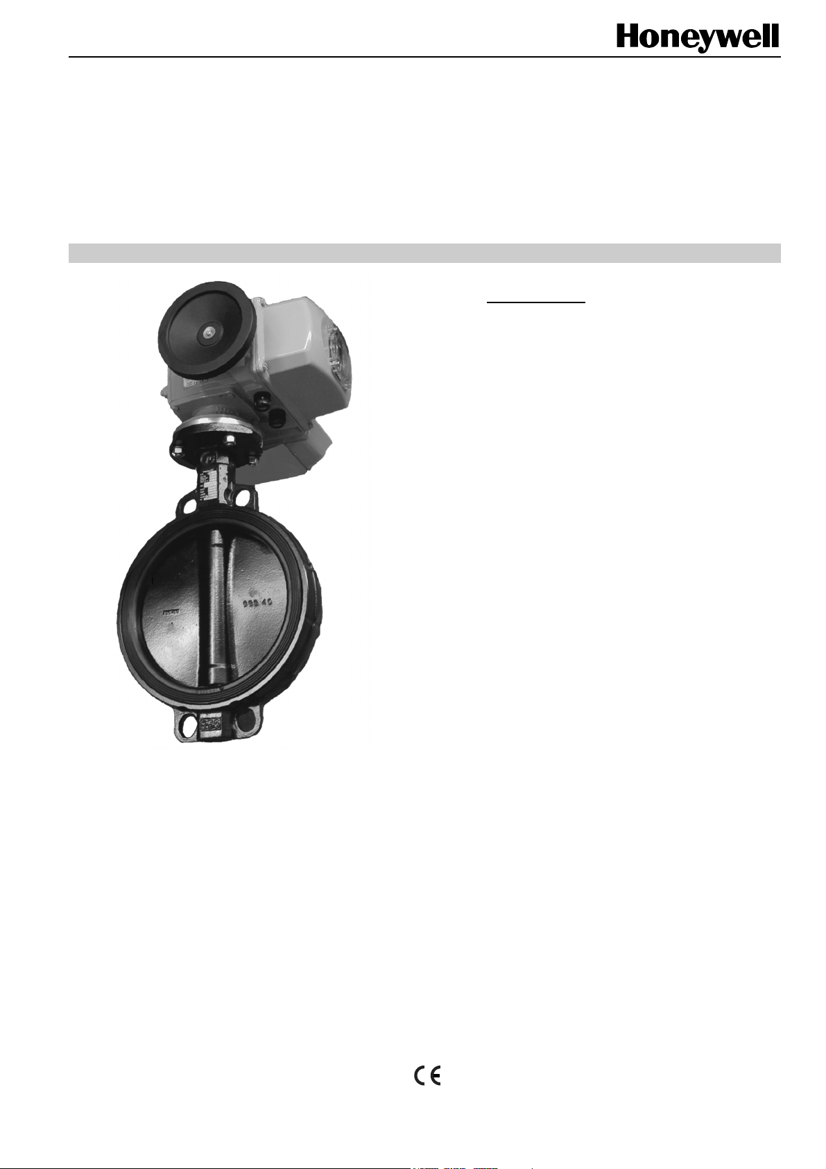
The V5422L and V5422E Actuated Butterfly Valves are
suitable for heating and cooling applications as well as in
boiler management systems. They can also be employed for
general services, water treatment, etc.
The V5422L series is equipped with floating-control actuators
(230 V, three-point).
The V5422E series is equipped with modulating-control
actuators with a standard control signal of 0...10 V (2...10 V,
0...20 mA, and 4...20 mA also possible).
The actuators and valves are delivered factory-mounted. The
position control and the end stops are completely justified.
V5422L / V5422E
ACTUATED BUTTERFLY VALVES
SPECIFICATION DATA
FEATURES
• With factory-mounted electric actuator
• Centric butterfly valve with elastomer liner
• Wide DN range (DN250 through DN400)
• For heating water containing up to 50% glycol
• Wafer body
• For modulating and floating control
• Maintenance-free control drive
• Mechanical setting indicator
• Manual adjustment wheel and declutch button
• Ample reserve torque
• Sizable terminal compartment for cabling
• Long unit lifetime
SPECIFICATIONS
Valves
Sizes DN250...DN400
Nominal pressure rating PN10
Shut-off pressure 10 bar
Tightness bubble-tight
Temperature of medium -10...+120 °C
Body Wafer, ductile iron GGG40
Liner EPDM
Disc ductile iron GGG40
coating: DeltaMagni
Shaft Stainless steel 1.4021
Actuators
Motor voltage 230 Vac (±10%), 50 to 60 Hz
Current, running time See Table 1
Angle of rotation 90°
Duty cycles max. 30% (class S4 IEC60034)
Running noise 65 dBA
Ambient temperature -20...+70 °C
Motor insulation class F according to VDE 0530
Protection class IP67 as per DIN 40050
Cable gland M20, cable ∅ 9...16 mm
Copyright © 2008 Honeywell Inc. • All rights reserved EN0B-0319GE51 R0108
Page 2
V5422L / V5422E ACTUATED BUTTERFLY VALVES
Table 1. Type list for different valve sizes and corresponding data
floating
version
V5422L1006 V5422E1001 0.8 1.6 30 250 250 5070 37.4
V5422L1014 V5422E1019 1.2 1.7 30 600 300 7430 45.5
V5422L1022 V5422E1027 1.2 1.7 30 600 350 10320 61
V5422L1030 V5422E1035 1.2 1.7 60 1000 400 13290 100
modulating
version
actuator current (A)
nominal start
run time
(sec)
actuator
torque (Nm)
valve size
(DN)
Kvs
(m3/h)
weight
(kg)
GENERAL CHARACTERISTICS
Position Indication and Running Status
The actuator's position is indicated by a mechanical pointer
located behind a window on the actuator's cover.
The actuator's running status is indicated by three LED's
located on the main PCB:
• The green LED (Op) is lit when the valve has been
opened.
• The red LED (Cl) is lit when the valve has been closed.
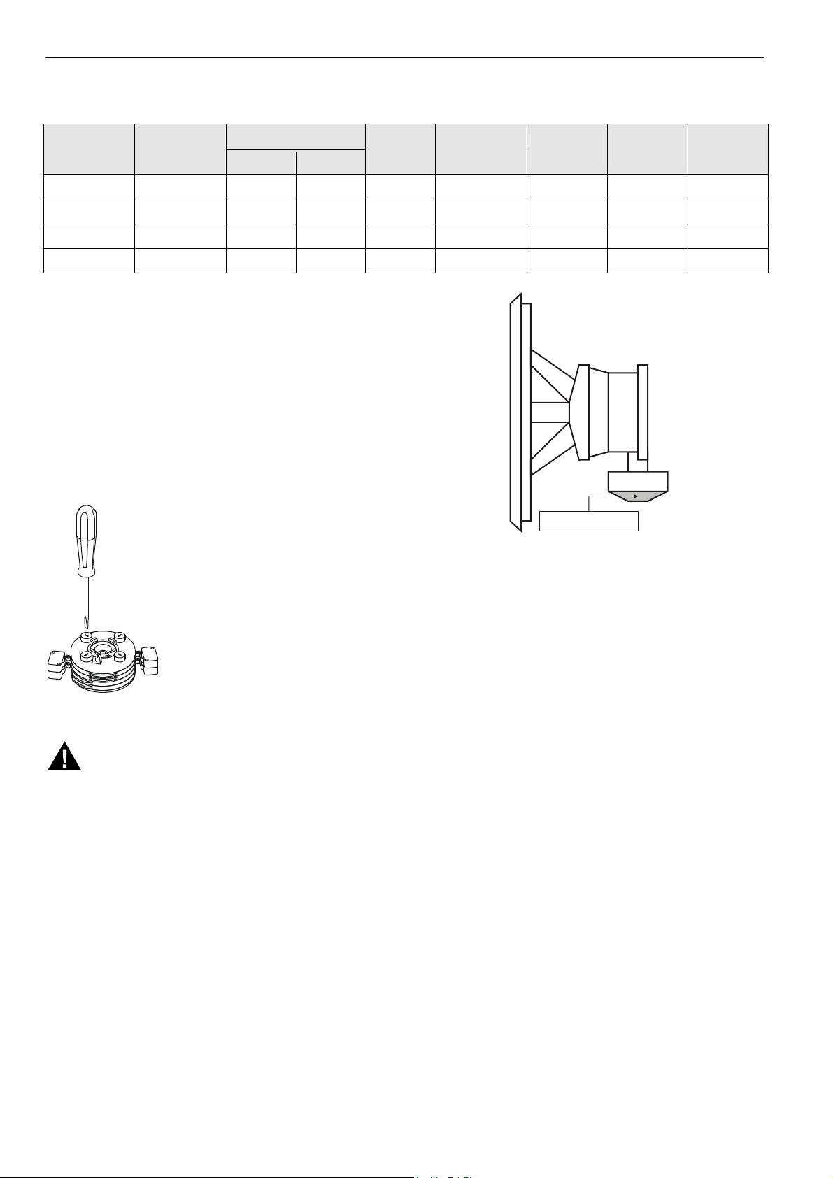
Angle Limitation
The angle at the drive shaft can be
adjusted to between 0° and 90°.
The end position is limited both electrically and mechanically. The electrical
limitation can be adjusted by pressing
and turning (with a screwdriver) the
adjustment screws situated on the
white and black cams.
The end position is factory-set to -2°
and +92°. As a rule, it is not necessary
to alter this value.
Manually Adjusting Valve
CAUTION
Before manually adjusting the valve, you must first
disconnect the power supply!
The valve can be manually adjusted using the manual
adjustment wheel and declutch button (see Fig. 1).
Fig. 1. Manual adjustment wheel and declutch button
The manual safety wheel is disengaged automatically when
the motor is running. To use the manual safety wheel, it must
therefore first be re-engaged using the declutch button.
Motor and Gear Protection
The actuator motor is protected against overheating by a
bimetal temperature monitor.
The motor and gear train are also protected against
mechanical overload by a torque limiter switch. The yellow
LED (Tq) is lit when the torque limiter has been activated.
Maintenance
The actuators are maintenance-free. They are lubricated for a
minimum of 100,000 operations.
If it becomes necessary to renew the grease completely, use
a lubricant complying with the following specifications:
• temperature range: -30...+135 °C
• penetration: ASTM 265/295 at 25 °C
• drop point: 180 °C
E.g. ELF Expecta 250, TOTAL Multis EP2, SHELL alvania
EP2, MOBIL Mobilux EP2, or ESSO Beacon EP2.
declutch button
EN0B-0319GE51 R0108 2
Page 3
V5422L / V5422E ACTUATED BUTTERFLY VALVES
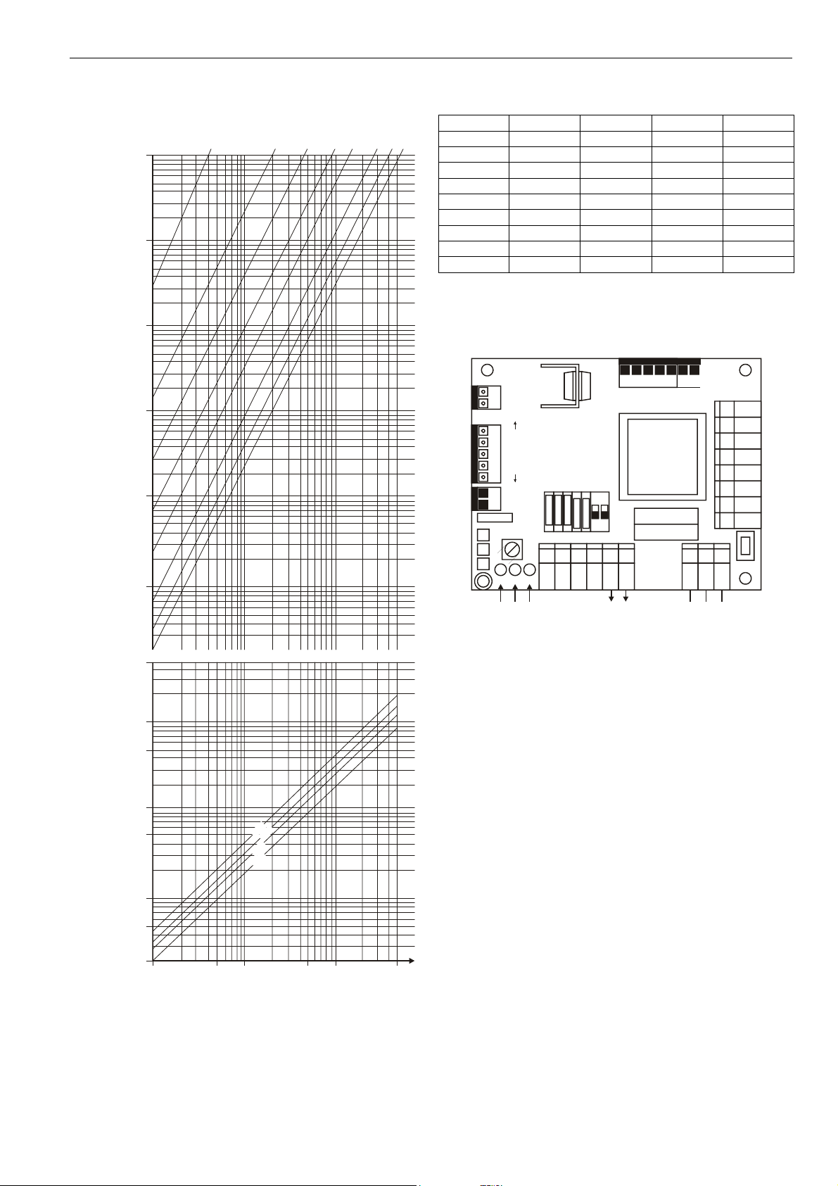
Flow Rate and Pressure Drop
°
0
2
pressure drop (bar)
10
1
0.1
0.01
0.001
0.0001
50000
°
0
1
Table 2. K
value (m3/h) vs. opening angle
V
DN250 DN300 DN350 DN400
°
0
3
0
0
5
4
0
0
0
9
7
6
10°
20°
30°
40°
50°
60°
70°
80°
90°
4 12 28 35
81 170 239 287
254 437 746 682
513 771 1400 1297
919 1338 2223 2190
1569 2237 3314 3777
2844 4037 5503 6529
4680 6850 9428 11786
5070 7430 10320 13290
°
°
°
°
°
V5422L (Floating Control)
The V5422L series is equipped with a main PCB (see Fig. 3)
located (together with the angle indicator) under the cover
(see Fig. 4). To access the main PCB, remove the cover.
Tr1 Tr2
1
2
18
17
16
17
18
4
9
Dead
Band
P1
Cl Op Tq
red/green/yellow LEDs
feedback jacks
microswitches
A
B
7
654321
70 71 72 73 31 32
70
71 72 73 31 32 L N PE
Fig. 3. Main PCB of the V5422L
input
15
12 14 11
10
Tr1
R2
R1
LNPE
power supply
27 26 41 40 1 2 3 3
Ful
10000
5000
1000
0
5
500
400
300
250
3
flow (cubic meters per h)
100
50
20
0.1 0.5 1 5 10 50
velocity (m/s)
Fig. 2. Flow rate and valve pressure drop
EN0B-0319GE51 R0108
3
Page 4

V5422L / V5422E ACTUATED BUTTERFLY VALVES
angle
indicator
main printed
circuit board
feedback
terminals
Fig. 4. Explosion view
Input Terminals
An external floating controller controls the actuator of the
V5422L. This controller transmits the phase to input 31 (for
closing the valve) or to input 32 (for opening the valve). See
also Fig. 12.
Feedback Terminals
The V5422L is equipped with two change-over switches (see
Fig. 5):
• terminals 20, 21, and 22 (provides a feedback signal that
the valve is in the OPEN position) and
• terminals 23, 24, and 25 (provides a feedback signal that
the valve is in the CLOSED position).
20
21
22
23
24
25
Fig. 5. Feedback terminals
NOTE: These change-over switches must be supplied with
power from an independent (external) power source
(maximum permissible load: 230 Vac, 16 A).
Adjusting the V5422L for Floating Control
A
B
7
Fig. 6. Default microswitch settings of the V5422L
• To adjust the V5422L for floating control, microswitches 5
and 6 (located on the main PCB; see Fig. 3) must both be
set to position "B" (see Fig. 6).
NOTE: In the case of the V5422L, microswitches 1, 2, 3,
and 4 have no function/effect.
5
6
3
4
ON
221
1
Adjusting the Direction of Rotation of the V5422L
• To adjust the direction of rotation so that the V5422L
closes in the clockwise (right) direction, microswitch 7
must be set to position "A".
• To set the direction of rotation so that the V5422L closes
in the counterclockwise (left) direction, microswitch 7 must
be set to position "B".
EN0B-0319GE51 R0108 4
Page 5

V5422L / V5422E ACTUATED BUTTERFLY VALVES
V5422E (Modulating Control)
The V5422E series is equipped with a main PCB (see Fig. 7)
located (together with a feedback potentiometer and the angle
indicator) under the cover (see Fig. 4). To access the main
PCB, remove the cover.
Tr1 Tr2
1
2
18
17
16
17
feedback jacks
18
microswitches
4
A
adjustment
9
Dead
Band
Cl Op Tq
red/green
/yellow LEDs
B
7
654321
70 71 72 73 31 32
70
71 72 73 31 32 L N PE
analog
input/output
P1
P2 offset
Fig. 7. Main PCB of the V5422E
Adjusting the V5422E for Modulating Control
A
B
7
6
Fig. 8. Default microswitch settings of the V5422E
• To adjust the V5422E for modulating control, microswitches 5 and 6 (located on the main PCB; see Fig. 7)
must both be set to position "A" (see Fig. 8).
Adjusting the Direction of Rotation of the V5422E
• To adjust the direction of rotation so that the V5422E
closes in the clockwise (right) direction, microswitch 7
must be set to position "A".
• To set the direction of rotation so that the V5422E closes
in the counterclockwise (left) direction, microswitch 7 must
be set to position "B".
See also section "Reversing Direction of Rotation of the
V5422E".
Adjusting the Input Signal Range of the V5422E
The input signal range (0/2...10 V or 0/4...20 mA) and the
corresponding output signal are set using microswitches 1, 2,
3, and 4 (see Table 3).
15
12 14 11
10
Tr1
R2
R1
LNPE
power supply
27 26 41 40 1 2 3 3
Ful
1
ON
5
3
4
221
Table 3. Adjusting the input signal range (V5422E)
Input
signal
output
signal
microswitch positions
1 2 3 4 5 6 7*
0…10 V 0…10 V B B B B A A A/B
2…10 V 2…10 V B B B A A A A/B
4…20 mA 4…20 mA A A A A A A A/B
0…20 mA 0…20 mA A A A B A A A/B
0…10 V 0…20 mA B B A B A A A/B
2…10 V 4…20 mA B B A A A A A/B
4…20 mA 2…10 V A A B A A A A/B
0…20 mA 0…10 V A A B B A A A/B
*Depends upon desired direction of rotation.
Terminals for Input/Output Signals
An external modulating controller controls the actuator of the
V5422E by means of an analog signal provided at terminal
70/71. An analog output signal for position indication is
provided at terminal 71/72.
Adjusting the Input/Output Signal Offset
The offset of modulating actuators is adjusted at the factory
and should not be changed. If you wish to change the offset
(using offset potentiometer P2; see Fig. 7), note that an
excessively small offset will result in oscillation of the
actuator.
Reversing Direction of Rotation of the V5422E
In the case of the V5422E, it is possible to reverse the
direction of rotation of the valve by adjusting the feedback
signals. The feedback signals are adjusted by resetting the
microswitches and replugging the feedback potentiometer's
cables. To do this, proceed as follows:
1. Turn the power off.
2. Reset the microswitches as shown in Table 3, but with
microswitch 7 in position B.
3. Replug the feedback potentiometer's cables as shown in
Fig. 9.
Fig. 9. Replugging the feedback potentiometer's cables
4. Apply the desired control signal (10 V or 20 mA, as the
case may be) for the closing position.
5. Turn the power back on.
6. Using a small screwdriver, adjust the potentiometer P1
(located on the main PCB; see Fig. 7) until the valve
closes completely.
EN0B-0319GE51 R0108
5
Page 6

V5422L / V5422E ACTUATED BUTTERFLY VALVES
VALVE MOUNTING
Install the actuated valve in the pipe according the following
steps (see also Fig. 10).
1. Spread the valve's flanges to facilitate installation. The
valve's disc must be partially open.
2. Set all stay-bolts while keeping the valve's disc slightly
open and without tightening the nuts.
3. Open the valve's disc completely. Ensure that the piping is
aligned. Tighten diagonally opposite the nuts until the
flanges are in contact with the body of the valve. Never
use gaskets or grease. Never weld the flanges after the
valve has been installed.
Step 1 Step 2 Step 3
Fig. 10. Installing the valve
Bolting
Table 4 lists the number of bolts and nuts required for
mounting. The number is dependent upon the size (DN).
Table 4. Bolts and nuts required for installation
DN
bolts (M x length) number
250 M20x150 12
300 M20x160 12
350 M20x160 16
400 M24x200 16
PN10
length
WIRING DIAGRAMS
PE
N
V5422L
V5422E
L
32
31
open (counterclockwise)
close (clockwise)
Fig. 12. Floating Control (V5422L)
PE
N
L
70
71
72
Fig. 13. Modulating Control (V5422E)
power supply:
power supply:
Y = 0...10 V
(2...10 V, 0/4...20 mA)
POS = 0...10 V
(2...10 V, 0/4...20 mA)
single-phase
230 Vac
single-phase
230 Vac
Fig. 11. Bolting
EN0B-0319GE51 R0108 6
Page 7

DIMENSIONS
Actuator Dimensions and Weight
Table 5. Actuator dimensions and weight
valve size
(DN)
250 479 167 308 81 177 18
300 509 169 315 89 177 17
350 509 169 315 89 177 17
400 564 172 417 133 167 30
M20
Fig. 14. Actuated butterfly valve (side view)
actuator dimensions (mm)
A B C D E
position indicator
weight
(kg)
V5422L / V5422E ACTUATED BUTTERFLY VALVES
Fig. 16. Actuated butterfly valve (cross-sectional view)
Valve Dimensions and Weight
E
valve size
(DN)
E
Table 6. Valve dimensions and weight
valve dimensions (mm)
A B C D H
250 273 203 68 324 243 19.4
300 302 232 78 378 292 29.4
350 358 258 78 425 333 43.8
400 407 287 102 475 383 66.6
2x M20
weight
(kg)
D
A
C
H
B
D
B
A
Fig. 15. Actuated butterfly valve (top view)
C
Fig. 17. Valve dimensions
EN0B-0319GE51 R0108
7
Page 8

Manufactured for and on behalf of the Environmental and Combustion Controls Division of Honeywell Technologies Sàrl, Ecublens, Route du Bois 37, Switzerland by its Authorized Representative:
Automation and Control Solutions
Honeywell GmbH
Böblinger Straβe 17
D-71101 Schönaich
Phone: (49) 7031 63701
Fax: (49) 7031 637493
http://ecc.emea.honeywell.com
Subject to change without notice. Printed in Germany
EN0B-0319GE51 R0108
 Loading...