

Page 1

APPLICATION
The V5197A is a firing rate valve used to provide variable
flow control of air, natural gas, liquefied petroleum (LP), and
manufactured gases. The V5197A is actuated by a firing rate
motor that can be mounted directly on the valve. The V5197A
is not applicable as a safety shutoff valve.
V5197A
Firing Rate Gas Valve
PRODUCT DATA
FEATURES
• Used with air, natural, manufactured or liquefied
petroleum (LP) gases.
• For modulating applications that do not require final
shutoff service of firing rate valve.
• Two valve body types (small and large) applicable to
seven pipe sizes:
• Small body type for 3/4 in. (19 mm), 1 in. (25 mm),
1-1/4 in. (32 mm), 1-1/2 in. (38 mm) and 2 in. (51 mm)
pipes, NPT or ISO 7 threads.
• Large body type for 2 in. (51 mm), 2-1/2 in. (64 mm)
and 3 in. (76 mm) pipes, NPT or ISO 7 threads.
• Two downstream 1/4 in. NPT threaded pressure taps
available.
• Accepts C6097 Pressure Switch mounted directly to
flange (downstream pressure tap only).
• Unpainted cast aluminum body.
• Suitable for electric or pneumatic operators with the
appropriate linkage.
• May be used with manufacturers own linkage and
drive motor.
• Flow adjustment screw on bottom of valve controls
maximum flow.
• Visual position indicator.
The V5197A is specially designed to provide fine control
of gas flow in applications where a high turn down ratio is
required.
The maximum flow adjustment screw on the bottom of the
valve allows adjusting the maximum flow of gas through the
V5197 while maintaining the linear modulating characteristics
and stroke.
The V5197A is part of the Honeywell Integrated Valve Train
System that allows gas train components to be directly bolted
together.
® U.S. Registered Trademark
Copyright © 2003 Honeywell International Inc.
All Rights Reserved
Contents
Application ........................................................................ 1
Features ........................................................................... 1
Specifications ................................................................... 2
Ordering Information ........................................................ 2
Installation ........................................................................ 5
Checkout and Operation .................................................. 8
Service Information .......................................................... 8
65-0247-2
Page 2
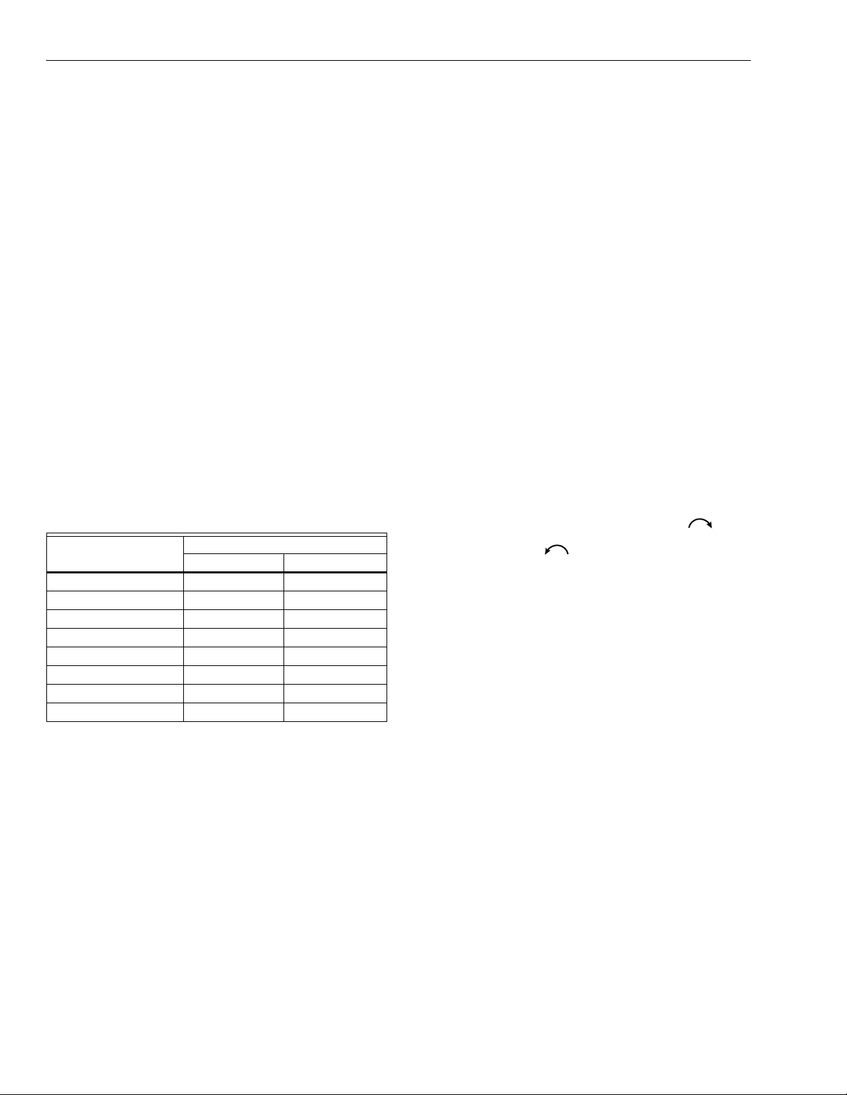
V5197A FIRING RATE GAS VALVE
SPECIFICATIONS
IMPORTANT
The specifications in this publication do not
include normal manufacturing tolerances; therefore,
an individual unit may not exactly match the
specifications listed. Also, this product is tested
and calibrated under closely controlled conditions,
and some minor differences in performance can be
expected if those conditions are changed.
Models:
V5197A1003: Small body.
V5197A1011: Large body.
Type of Gas: Air, natural, manufactured, mixed or liquefied
petroleum (LP) gases only.
Pipe Size of the gas train: 3/4 in. (19 mm), 1 in. (25 mm),
1-1/4 in. (32 mm), 1-1/2 in. (38 mm), 2 in. (51 mm),
2-1/2 in. (64 mm), 3 in. (76 mm).
Pressure Rating: Maximum operating pressure of 15 psi
(1 Bar).
Maximum Valve Capacities: SCFH gas: 0.64 sp. gr. at
1 in. wc pressure drop across valve (flow limit adjustment
set at 100% open). See Table 1.
(natural gas at 0.64 sp.gr.) at 1 in. w.c. (2.5 mBar)
Pipe Size in in. (mm)
3/4 (19) 2450 69
1 (25) 3080 87
1-1/4 (32) 4430 125
1-1/2 (38) 5010 142
2 (51)—small body 5480 155
2 (51)—large body 12,600 356
2-1/2 (64) 14,800 419
3 (76) 16,900 478
a
Standard cubic feet per hour (SCFH) and standard cubic
meters per hour (SCMH) listed. For other gases, multiply the
listed capacity by the square root of (0.64 divided by the
specific gravity of the other gas).
Flow curves: See Fig. 1 through 8.
Table 1. Maximum Flow Capacity
Pressure Drop Across Valve.
Flow Capacity
SCFH SCMH
a
NOTE: The percentage settings listed on the figures refer
to the setting of the flow adjustment screw on the
bottom of the V5197. Pressure drops are shown as
solid, broken or dotted lines on the figures.
Bolt/Nut Fasteners (Provided with the valve):
Small body: 3/8-16 by 1-3/8, Grade 5 bolt. Metric equivalent
M8x1.25x35mm, class 9.8. Tighten to 13 ft-lb (18 N•m).
Large body: 1/2-13 by 2.00, Grade 5 bolt. Metric equivalent
M12x1.75x50mm, class 9.8. Tighten to 25 ft-lb
(34 N•m).
Tapping and plug: Two downstream 1/4 in. NPT taps.
Plugs : 1/4 in. hex socket.
Ambient Operating Temperature Rating: -40°F to +150°F
(-40°C to +66°C).
Material: Cast aluminum body, brass and stainless steel
internal parts, NBR seals.
Mounting: Directly bolted to Integrated Valve Train (IVT)
components or IVT adapters.
Mechanical Strength: Group 2.
Maximum flow adjustment (Fig 9):
Located on the bottom of the valve with a 1/4 in. (6 mm)
hex key:
To decrease the maximum flow, turn clockwise ;
to increase the maximum flow, turn
counterclockwise .
Mounting position: Any position.
Dimensions: See Fig. 10 and 11.
Weight:
Small Body—5-1/4 lb (2.4 kg).
Large Body— 11-5/8 lb (5.3 kg).
Accessory: 201391 Shaft Adapter for 3/8 in. (10 mm) round
or square shaft (provided with both small body and large
body valves.
Approvals:
Underwriters Laboratories, Inc. (UL).
CSA.
EN161 Approval requires the use of an EN161-approved
actuator.
CE.
ORDERING INFORMATION
When purchasing replacement and modernization products from your TRADELINE® wholesaler or distributor, refer to the
TRADELINE® Catalog or price sheets for complete ordering number.
If you have additional questions, need further information, or would like to comment on our products or services, please write or
phone:
1. Your local Honeywell Automation and Control Products Sales Office (check white pages of your phone directory).
2. Honeywell Customer Care
1885 Douglas Drive North
Minneapolis, Minnesota 55422-4386
In Canada—Honeywell Limited/Honeywell Limitée, 35 Dynamic Drive, Scarborough, Ontario M1V 4Z9.
International Sales and Service Offices in all principal cities of the world. Manufacturing in Australia, Canada, Finland, France,
Germany, Japan, Mexico, Netherlands, Spain, Taiwan, United Kingdom, U.S.A.
65-0247—2 2
Page 3
V5197A FIRING RATE GAS VALVE
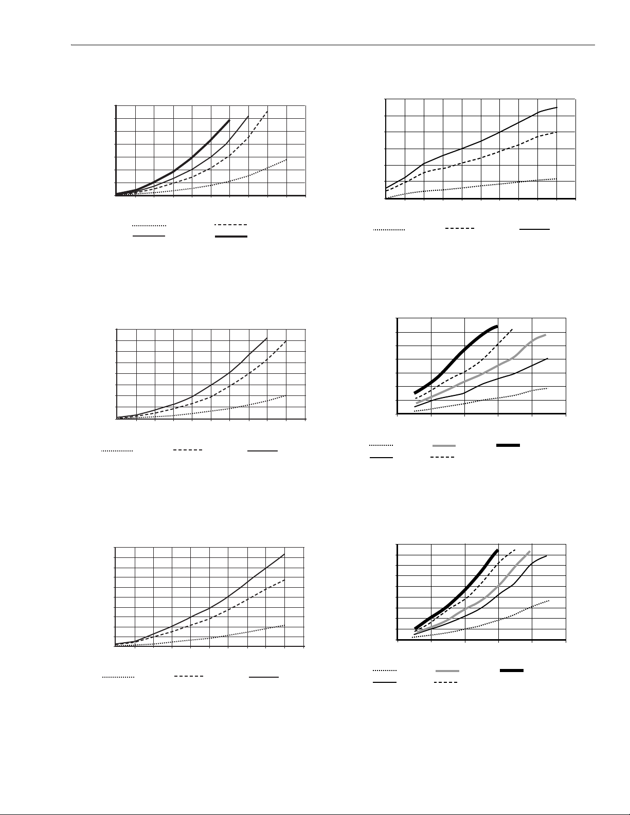
B
FLOW 0.64 s.g. GAS (cfh)
V5197A1003
0
FLOW 0.64 s.g. GAS (cfh)
V5197A1003
0
M17523B
FLOW 0.64 s.g. GAS (cfh)
V5197A1003
0
B
FLOW 0.64 s.g. GAS (cfh)
V5197A1003
0
FLOW 0.64 s.g. GAS (cfh)
0
V5197A1011
FLOW 0.64 s.g. GAS (cfh)
0
A
V5197A1011
14000
12000
10000
8000
6000
4000
2000
0
0 10203040506070809010
1 INCH
20 INCH
100%
DEGREE OPEN
10 INCH
40 INCH
M17521
Fig. 1. V5197A (small body) flow curves at stated
pressure drops with flow adjustment set at 100%.
16000
14000
12000
10000
8000
6000
4000
2000
0
0 102030405060708090
1 INCH
75%
DEGREE OPEN
10 INCH
20 INCH
M17522B
3000
2500
2000
1500
1000
500
0
0 102030405060708090
1 INCH
25%
DEGREE OPEN
10 INCH
10
20 INCH
M17524
Fig. 4. V5197A (small body) flow curves at stated
pressure drops with flow adjustment set at 25%.
14000
12000
10000
8000
6000
4000
2000
0
10
020406080
1 INCH
5 INCH
25%
DEGREE OPEN
10 INCH
20 INCH
10
40 INCH
M17894A
Fig. 2. V5197A (small body) flow curves at stated
pressure drops with flow adjustment set at 75%.
10000
9000
8000
7000
6000
5000
4000
3000
2000
1000
0 102030405060708090
1 INCH
50%
DEGREE OPEN
10 INCH
20 INCH
Fig. 3. V5197A (small body) flow curves at stated
pressure drops with flow adjustment set at 50%.
Fig. 5. V5197A (large body) flow curves at stated
pressure drops with flow adjustment set at 25%.
18000
16000
14000
12000
10000
8000
6000
4000
2000
10
020406080
1 INCH
5 INCH
50%
DEGREE OPEN
10 INCH
20 INCH
30 INCH
M17895
Fig. 6. V5197A (large body) flow curves at stated
pressure drops with flow adjustment set at 50%.
3 65-0247—2
10
Page 4

V5197A FIRING RATE GAS VALVE
FLOW 0.64 s.g. GAS (cfh)
V5197A1011
0
A
A
4
16000
14000
12000
10000
8000
6000
4000
2000
0
020406080
1 INCH
2 INCH
75%
DEGREE OPEN
5 INCH
10 INCH
20 INCH
Fig. 7. V5197A (large body) flow curves at stated
pressure drops with flow adjustment set at 75%.
V5197A 1011
18000
16000
14000
12000
10000
8000
6000
4000
FLO W 0.64 s.g. G AS (cfh)
2000
100%
M17896
32000109-005 2 in. (51 mm—small body valve only.
32001605-001 2 in. (51 mm)—large body valve only.
32001605-002 2-1/2 in. (64 mm).
32001605-003 3 in. (76 mm).
Pipe Adapters, BSP:
32000109-006 3/4 in. (19 mm).
32000109-007 1 in. (25 mm).
32000109-008 1-1/4 in. (32 mm).
32000109-009 1-1/2 in. (38 mm).
32000109-010 2 in. (51 mm)—small body valve only.
32001605-004 2 in. (51 mm)—large body valve only.
32001605-005 2-1/2 in. (64 mm).
32001605-006 3 in. (76 mm).
10
4074EYE Bag Assembly (bolts, nuts and washers for large
body valve), supplied.
4074EYF Bag assembly (bolts, nuts and washers for small
body valve), supplied.
4074EYK Bag Assembly (O-rings and tube of lubricant for
small body valve), supplied.
4074EYL Bag Assembly (O-rings and tube of lubricant for
large body valve), supplied.
The following non-part-numbered items are provided with
the valve:
ML7999 Actuator Mounting Bracket
Mounting Bracket Screws
Valve Drive Stem
020406080
DEGREE OPEN
.5 INCH
1 INCH
5 INCH
10 INCH
20 INCH
60 INCH
100
M17897
Fig. 8. V5197A (large body) flow curves at stated
pressure drops with flow adjustment set at 100%.
Accessories:
201391 3/8 in. Shaft Adapter for mounting ML7999A/B to
V5197.
Pipe Adapters, NPT:
32000109-001 3/4 in. (19 mm).
32000109-002 1 in. (25 mm).
32000109-003 1-1/4 in. (32 mm).
32000109-004 1-1/2 in. (38 mm).
FLOW
ADJUSTMENT
Fig. 9. V5197 Flow Adjustment.
M1763
65-0247—2 4
Page 5

V5197A FIRING RATE GAS VALVE
1
)
2
1
6
V
D
S
V
P
I
S
0-5/16
(277)
4-27/32 (123)
2-1/2 (64)
6-7/16 (165)
7-1/8
(181
3-25/3
(96)
M17528
2-11/16
(322)
4-13/16 (122)
4 (102)
9-1/4 (235)
7-15/1
(202)
4-3/4
(121)
M17898
Fig. 10. V5197A Firing Rate Gas Valve (small body), with
mounting bracket (included) and ML7999 Actuator
(not supplied), dimensions in in. (mm).
Fig. 11. V5197A Firing Rate Gas Valve (large body), with
mounting bracket (included) and ML7999 Actuator (not
supplied), dimensions in in. (mm).
INSTALLATION
Installing the Valve Drive Stem in the V5197
When Installing this product…
1. Read these instructions carefully. Be sure to follow
Warning information carefully.
2. Check the ratings given in the instructions and on
the product to make sure the product is suitable for
your application.
3. Installer must be a trained, experienced flame
safeguard control technician.
4. After installation is complete, check out product
operation as provided in these instructions.
1. Place the short end of the Valve Drive Stem in the top of
the V5197 Valve drive so that the square portion of the
drive stem is fully engaged in the square hole in the
valve drive assembly. See Fig. 12.
NOTE: The short end of the Valve Drive Stem is
1 in. (25 mm) in length (measured from the square
portion of the stem); the long end of the Valve
Drive Stem is 1-1/8 in. (35 mm) long.
2. Tighten the valve position indicator setscrew (located
in the valve drive assembly) to a torque setting of
5 inch-pounds (80 inch-ounces/6 kg-cm).
WARNING
Explosion Hazard and Electrical Shock Hazard.
Can cause explosion, serious injury or death.
1. Turn off gas supply before starting installation.
2. Disconnect power supply for valve actuator
(if applicable) before beginning installation.
More than one disconnection can be involved.
Installation
ALVE
RIVE
TEM
ALVE
OSITION
NDICATOR
ETSCREW
IMPORTANT
Install the valve so the arrow on the valve body
points in the gas flow direction.
M17686
Fig. 12. Inserting the Valve Drive
Stem in the V5197 Valve.
5 65-0247—2
Page 6

V5197A FIRING RATE GAS VALVE
Installing the V5197 in the IVT
Refer to the Integrated Valve Train Installation instructions
(form 66-1099) for complete instructions on mounting a
V5197A in a Honeywell Integrated Valve Train System.
Allow sufficient clearance for assembling the motor and
linkage (if applicable), and for general servicing.
IMPORTANT
Install the valve so the arrow on the valve body
points in the gas flow direction. Make sure the O-ring
seals (provided) are properly positioned and seated
at the inlet and outlet flange connections.
1. Install the V5197 Valve so the arrow on the valve body
points in the gas flow direction.
NOTE: Normally, the V5197 will be located
downstream of the safety shutoff valve(s) in
the Integrated Valve Train.Refer to form
66-1099 or the following steps.
2. Using the grease packet provided (or equivalent,
general purpose, lithium grease), grease the O-rings
provided with the valve. Make sure the grease is applied
evenly around the O-ring. See Fig. 13.
3. Connect the V5197 Valve to the safety shutoff valve
(SSOV) using three bolts, nuts and lockwashers as
shown in Fig. 13.
NOTE: Tightening torque for nuts/bolts:
• Small body flanges: 13 ft-lb (18 N-m).
• Large body flanges: 25 ft-lb (34 N-m).
4. Connect the pipe adapter to the other end of the V5197
Valve using three bolts, nuts and lockwashers.
5. Assemble the downstream gas piping:
a. Use new, properly reamed, pipe, free from chips.
b. Apply moderate amounts of good quality pipe dope,
resistant to the action of liquid propane (LP) gas,
on the pipe threads. See Fig. 14.
c. Do not thread pipe too far into pipe adapter.
The pipe should end flush with the O-ring sealing
surface of the pipe adapters. Valve distortion or
malfunctions can result from excess pipe in the
valves.
6. Mount the ML7999 Actuator on the V5197 Valve and
secure the actuator to the mounting bracket.
7. Wire the ML7999 Actuator according to instructions
in form no. 65-0239.
8. Restore power to the system.
GREASE
PACKET
GREASE
PACKET
O-RING
PIPE ADAPTER
Fig. 13. Mounting the V5197 Valve in the IVT.
Mounting the ML7999 Mounting Bracket
The ML7999 Actuator and mounting bracket can be installed
in one of four positions, depending on accessibility of the
valve and actuator. See Fig. 15.
VALVE
V5197
O-RING
3 BOLTS ON
EACH SIDE
M17681
1. Choose the actuator and bracket position best suited for
your location and place the mounting bracket over the
drive shaft of the V5197 valve. See Fig. 16.
2. Manually open the V5197 valve for proper alignment of
the ML7999 Actuator.
3. Secure the mounting bracket with the three screws
provided.
65-0247—2 6
Page 7

V5197A FIRING RATE GAS VALVE
INCORRECT:
T
CORRECT: NORMAL
0
7
G
2
S
A
7
FULL THREAD
TWO CLEAN THREADS
WITH MODERATE
AMOUNT OF DOPE
PIPE
ADAPTER
CORRECT
USE PIPE DOPE RESISTANT
1
TO ACTION OF LP GAS.
DISTORTS VALVE SEAT
LOOSE
CHIPS
1
REAM PIPE AND BLOW
OUT CHIPS (TO AVOID
LODGING ON SEAT)
TOO LONG,
EXCESS DOPE
CAN BLOCK DISK
FROM VALVE SEA
PIPE
ADAPTER
INCORRECT:
TOO LONG,
DISTORTS VALVE SEAT
M1641
Fig. 14. Preparing pipes.
Mounting the ML7999 Actuator
1. Insert the shaft adapter and place the actuator over the
shaft. Position and seat the actuator.
ML7999
MOUNTIN
BRACKET
Fig. 15. Possible mounting positions of the
ML7999 Actuator and mounting bracket.
V519
M17682
NOTE: Use the 201391 shaft adapter (included with
the valve) to mount the ML7999 Actuator to the
V5197 Valve drive stem. Place the adapter as
shown in Fig. 16 so that the valve drive shaft is
between the adapter and the four setscrews.
2. Secure the actuator to the mounting bracket using a
bolt, nut and locking washer. See Fig. 17.
CAUTION
Equipment Damage Hazard.
Improper alignment can damage the actuator.
Align the ML7999 Actuator bottom panel parallel with
the ML7999 mounting bracket (Fig. 18). Failure to do
so will cause undue stress on the actuator motor and
shorten its operating life.
3. Partially tighten the four hub setscrews to ensure that
the actuator seats firmly against the mounting bracket
with the shaft centered in the actuator hub. See note 1
in Fig. 18.
4. Tighten the anti-rotation bolt to the torque
recommendation for the selected bolt/nut.
5. Tighten the hub setscrews against the shaft to a torque
of 60 in-lb (69 kg-cm). See Fig. 17.
M17685
Fig. 16. Attaching the ML7999 Actuator mounting bracket
to the V5197 Valve (valve in the open position).
01391
HAFT
DAPTER
ML7999A/B
ACTUATOR HUB
V5197
DRIVE STEM
7 65-0247—2
Fig. 17. Proper positioning of 201391 shaft adapter
and V5197 drive shaft.
ML7999
SETSCREWS
M2102
Page 8

V5197A FIRING RATE GAS VALVE
)
ML7999
1
HUB
SCREWS
1
V5197
1
ML7999 MUST BE MOUNTED PARALLEL WITH MOUNTING BRACKET.
ANTI-ROTATION
BOLT AND LOCKING
NUT (NOT SUPPLIED
ML7999
MOUNTING
BRACKET
M17683
replaced (see Service Information section). It is recommended
that this test also be included in the scheduled inspection and
maintenance procedures.
NOTE: Additional leakage and closure tests may be required
for other gas train components (for example, safety
shutoff valves [SSOV]).
1. Close the downstream manual gas valve(s).
2. Energize the valve train to apply gas pressure.
3. Test with rich soap and water solution to make sure
there is no leak at any pipe adapter/valve mating
surfaces.
4. Restore the system to normal operation.
Fig. 18. Mounting the ML7999 Actuator
on the V5197 Valve.
CHECKOUT AND OPERATION
Checkout
WARNING
Explosion Hazard and Electrical Shock Hazard.
Can cause explosion, serious injury or death.
1. Do not allow fuel to accumulate in the combustion
chamber for longer than a few seconds without
igniting. An explosive mixture can result.
2. Do not put the system into service until you have
satisfactorily completed the following Valve Leak
Test, all applicable tests described in the Checkout
section of the instructions for the flame safeguard
control, and any other tests required by the burner
manufacturer.
3. All tests must be performed by a trained,
experienced flame safeguard control technician.
4. Close all manual fuel shutoff valves as soon as
trouble occurs.
After the installation is completed, cycle the valve several
times with the manual fuel shutoff cock closed. Make sure the
valve and actuator function properly. Also perform the Valve
Leak Test before putting the valve into service.
Valve Leak Test
This is a test for checking the leakage tightness of the firing
rate gas valve only. It should be performed only by trained,
experienced flame safeguard control technicians during the
initial startup of the burner system, or whenever the valve is
Operation
A V5197A Firing Rate Gas Valve is operated by an actuator.
The valve opens counterclockwise and closes
clockwise . When closed, the valve does not totally seal
off the gas flow and has no safety shutoff function. For further
information, refer to the actuator instructions.
Make sure that the actuator does not force the V5197 Valve
beyond the limits of the valve stroke (90 degrees). This can
damage or destroy the valve position indicator setscrew.
SERVICE INFORMATION
WARNING
Explosion Hazard and Electrical Shock Hazard.
Can cause explosion, serious injury or death.
1. Turn off the gas supply and disconnect all electrical
power to the valve actuator before servicing.
2. Properly position and seat the seals in ends of the
valve body to prevent a hazardous gas leak.
Read these instructions and form 66-1099 carefully
for servicing information.
IMPORTANT
Only trained, experienced flame safeguard control
technicians should attempt to service or repair flame
safeguard controls and burner assemblies.
Scheduled Inspection and Maintenance
Set up and follow a schedule for periodic inspection and
maintenance for the burner, all other controls and the valves.
It is recommended that the valve leak test in the Operation
and Checkout section be included in this schedule. Refer to
the instructions for the primary safety control and safety
shutoff valve(s) for more information.
Automation and Control Solutions
Honeywell International Inc. Honeywell Limited-Honeywell Limitée
1985 Douglas Drive North 35 Dynamic Drive
Golden Valley, MN 55422 Scarborough, Ontario
65-0247—2 G.R. Rev. 06-03 www.honeywell.com
M1V 4Z9
Printed in U.S.A. on recycled
paper containing at least 10%
post-consumer paper fibers.
 Loading...