

Honeywell V5100 User Manual
V5100
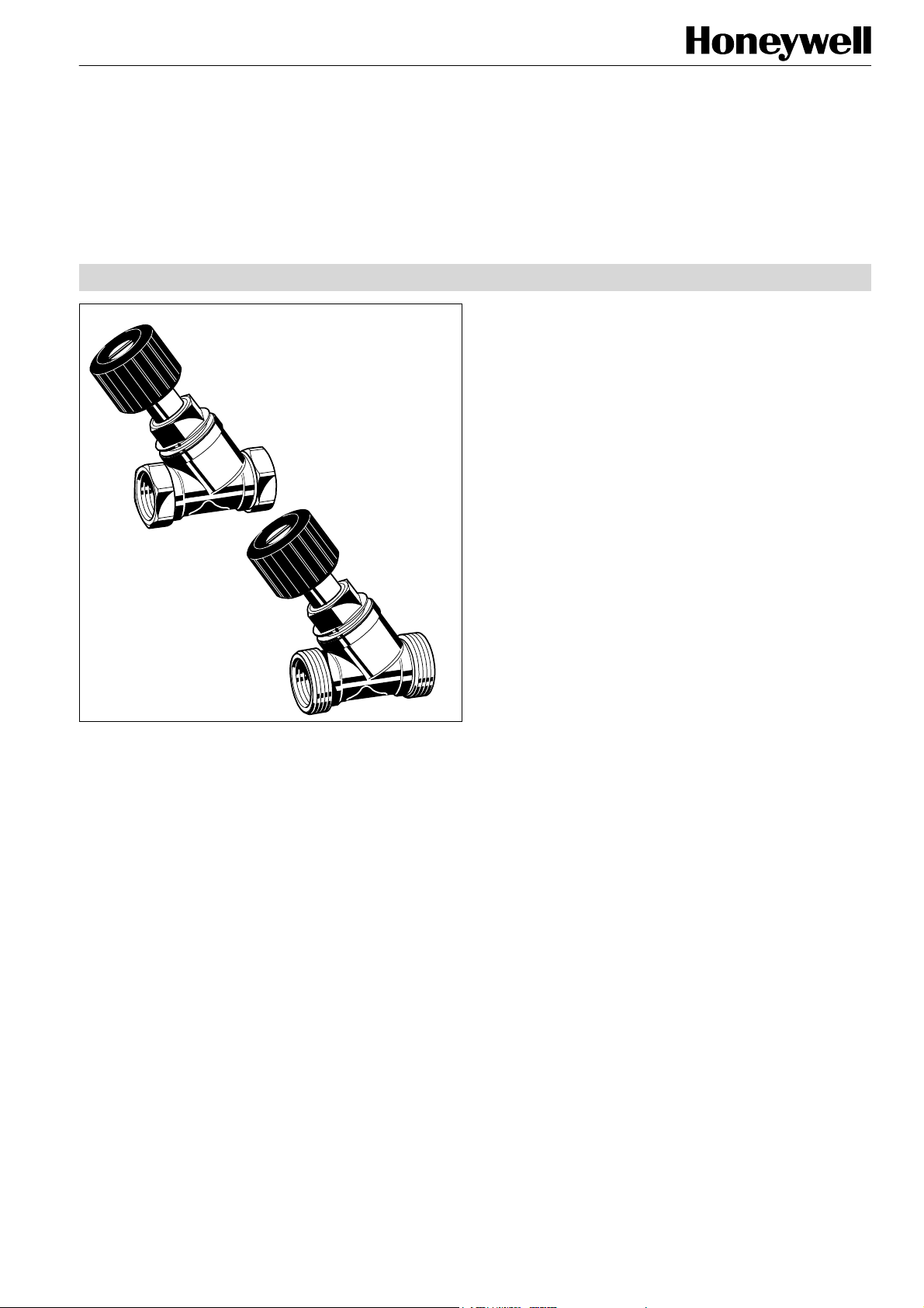
Stop Valve-3
RED BRONZE Y-PATTERN SHUTOFF VALVE
Stop Valve-3
with internal threads
Stop Valve-3
with external threads
Design
The valve consists of:
• Y-pattern valve body PN16, DN10...DN40 with internal
threads to DIN2999 (ISO7) for threaded pipe.
DN10...DN20 also for copper and precision steel pipe
10...22 mm using compression pipe fittings (see ‘Accessories’ on page 4), or
• Y-pattern valve body PN16, DN10…DN40 with external
threads to ISO228 for use with connections (see ‘Accessories’)
• Valve insert
• Handwheel
Materials
• Valve housing made of red bronze
• Valve insert made of brass
• Seat seal made of PTFE
• Spindle seals made of EPDM
• Handwheel made of black plastic
Application
PRODUCT DATA
V5100 type valves are used as shutoff valves in hydronic
heating and cooling systems. The valves further have an
integrated draining support. The draining function can be
used with the standard Kombi-System draining adapter (see
‘Accessories’ further below).
They can also be used to connect the impulse tube of Kombi3-plus, Kombi-2-plus and Kombi-PC differential pressure
controllers.
Features
• Valve body made of corrosion-resistant red bronze
• Integrated draining function with adapter
• High flow rates
• Available from DN10 to DN40
Specifications
Medium Water or water-glycol mixture
pH-value 8...9,5
Operating temperature 2...130°C (36...266°F)
Operating pressure max. 16 bar (232 psi)
k
vs (cv)-values DN10 2.5 (2.9)
DN15 2.5 (2.9)
DN20 7.0 (8.2)
DN25 7.0 (8.2)
DN32 22.0 (25.7)
DN40 22.0 (25.7)
Function
The valve is normally open so the medium can flow. The
valve is closed by turning the handwheel clockwise until tight
and the pipeline is shutoff.
Copyright © 2004 Honeywell International Inc. • All rights reserved EN0H-0277GE25 R1204
STOP VALVE-3 (V5100)
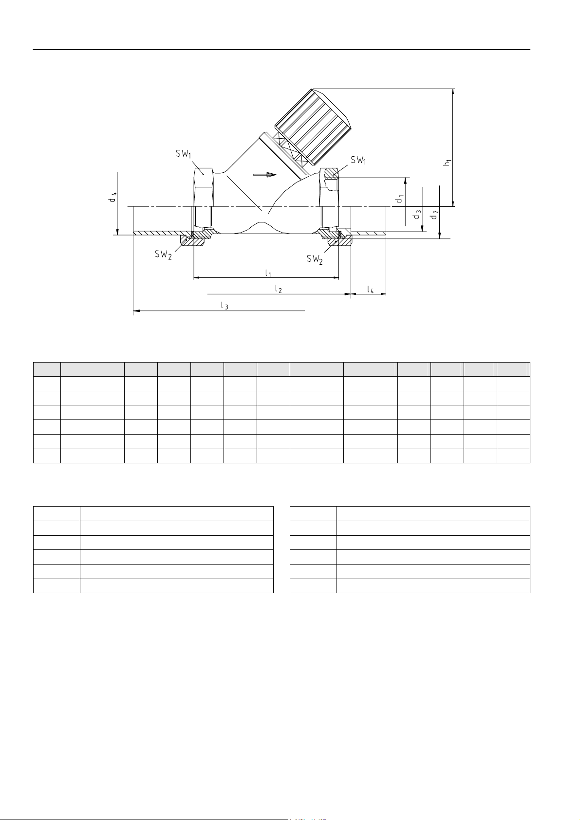
Dimensions
Fig. 1. Side view
Table 1. Dimensions
DN kvs (cv)-value h1 l1 l2 l3 l4 d1 d2 d3 d4 SW1 SW2
10
15
20
25
32
40
2.5 (2.9) 60 60 74 110 10
2.5 (2.9) 65 65 81 125 12
7.0 (8.2) 70 75 92 146 17
7.0 (8.2) 72 90 108 170 20
22.0 (25.7) 120 110 128 200 25
22.0 (25.7) 120 120 140 220 29
Rp3/8”
Rp1/2”
Rp3/4”
Rp1”
Rp1 1/4”
Rp1 1/2”
G5/8”A 12 16 22 27
G3/4”A 15 20,5 27 30
G1”A 22 26 32 37
G1 1/4”A 28 33 41 47
G1 1/2”A 35 41 50 52
G1 3/4”A 42 47,5 55 60
NOTE: All dimensions in mm unless otherwise stated.
Table 4. Abbreviations used for dimensions
DN
d1
d2
d3
d4
h1
Nominal size
Internal thread on body (connection size)
External thread on body
Inner Ø of connection
Outer Ø of connection
Height with valve fully open
l1
l2
l3
l4
SW1
SW2
Body length according to DIN3502
Installed length with soldering connections
Installed length with welding connections
Length of pipe penetration
Wrench size
Wrench size union-nut (not supplied with valve)
NOTE: The V5100X… is not supplied with union-nuts and sealing rings.
EN0H-0277GE25 R1204 2 Honeywell GmbH • All rights reserved
 Loading...