

Page 1
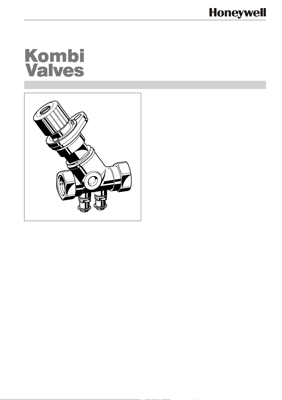
V5032
Kombi-2-plus
BALANCING AND SHUTOFF VALVE
PRODUCT DATA
CONTENTS
Design...................................................................................1
Materials................................................................................1
Application............................................................................1
Features................................................................................1
Specifications.......................................................................2
Function................................................................................2
Dimensions, kvs-values and Ordering Information ..........2
Accessories..........................................................................3
Connections .......................................................................3
Accessories........................................................................ 3
Measuring equipment.........................................................3
Spare parts.........................................................................3
Flow Data.................................................................... 4 to 11
Influence of Coolants on Flow Values..............................12
Correction Factor f ...........................................................12
Design
The Kombi-2-plus valve consists of:
•
Valve body with pressure test cocks and internal threads
DN10...DN20 to DIN2999 (ISO7) for threaded pipe or copper and precision steel pipe 10...20 mm (see Accessories),
or
•
Valve body DN25...DN80 with pressure test cocks and
internal threads to DIN2999 (ISO7) for threaded pipe
•
Valve insert
•
Blue handwheel with pre-setting dial and display
Materials
•
Valve housing made of red bronze
•
Valve insert and pressure test cocks made of brass
•
O-rings and soft seals made of EPDM
•
Handwheel, pre-setting dial and display made of plastic
Application
The Kombi-2-plus is installed in the return mains of pump
driven warm water heating systems and cold water cooling
systems to regulate the hydronic balance and as shutoff
valve. The Kombi-2-plus has an O-ring spindle seal and is
maintenance free. The valve body can be insulated easily
and is equipped with pressure test cocks for differential pressure or flow measurement.
Further functions can be retrofitted without interrupting operation of the system: draining, filling and automatic regulation
(in combination with a Kombi-3-plus BLACK valve in the supply and a Kombi-Diaphragm Unit).
Features
• Maintenance free spindle with double O-ring sealings
• PTFE seat sealing
• High accuracy of the pre-setting because of individual
adjustment
• Valve body PN16
• Dimensions DN15 to DN40 can be retrofitted with a
Kombi-Diaphragm Unit
• Robust valve body made of corrosion resistant red
bronze
• Availabe in sizes up to DN80
• Visible pre-setting dial with concealed pre-setting
wheel
Copyright © 2002 Honeywell AG • All rights reserved EN0H-0048GE25 R0402
Page 2
KOMBI-2-PLUS (V5032)
Specifications
Medium
Operating temperature
Operating pressure
Differential pressure
vs
(cv)-values
k
NOTE: Differential pressure: Closing pressure for
Kombi-2-plus with installed Kombi-Diaphragm Unit.
Regarding noise generation the conditions, requirements and installation design have to be taken into
account.
Water, water-glycole mixture
2...130°C (36...266°F)
max. 16 bar (232 psi)
max. 2,0 bar (29 psi) –
see NOTE below
see table on page 2
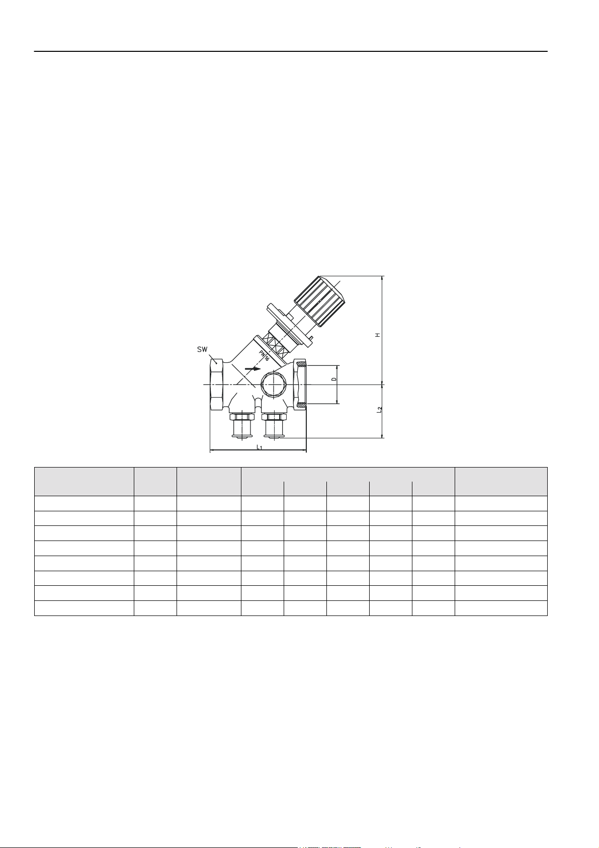
Dimensions, kvs-values and Ordering Information
Function
The hydronic balance is a significant requirement for the
efficient operation of a hydronic heating or cooling installation.
In an unbalanced system under or over provision of hot water
to individual radiators or circuits can occur. Apart from the
correct selection of radiator valves, regulation of individual
circuits is also necessary and in some cases, such as in
DIN 18 380, VOB part C, is required by national standards.
This requirement is met with the shutoff and balancing valve
Kombi-2-plus. The Kombi-2-plus for the return has the functions shutoff, pre-setting, regulation (with diaphragm unit,
accessory), draining and filling (draining adapter, accessory).
Type DN kvs (cv)- Dimensions OS-No.
value D H L
Internal threads 15 2,7 (3,16) Rp1/2” 85 65 41 27 V5032Y0015
Internal threads 20 6,4 (7,49) Rp3/4” 100 75 42 32 V5032Y0015
Internal threads 25 6,8 (7,96) Rp1” 100 90 45 41 V5032Y0015
Internal threads 32 21,0 (24,6) Rp1 1/4” 137 110 46 50 V5032Y0015
Internal threads 40 22,0 (25,7) Rp1 1/2” 137 120 49 55 V5032Y0015
Internal threads 50 38,0 (44,5) Rp2” 158 150 55 70 V5032Y0015
Internal threads 65 47,7 (55,8) Rp2 1/2” 195 180 68 85 V5032Y0015
Internal threads 80 71,0 (83,1) Rp3” 210 200 75 100 V5032Y0015
NOTE: All values in mm if not stated otherwise.
Dimension ‘H’ refers to fully open valve.
1
2
L
SW
EN0H-0048GE25 R0402 2 Honeywell AG • All rights reserved
Page 3
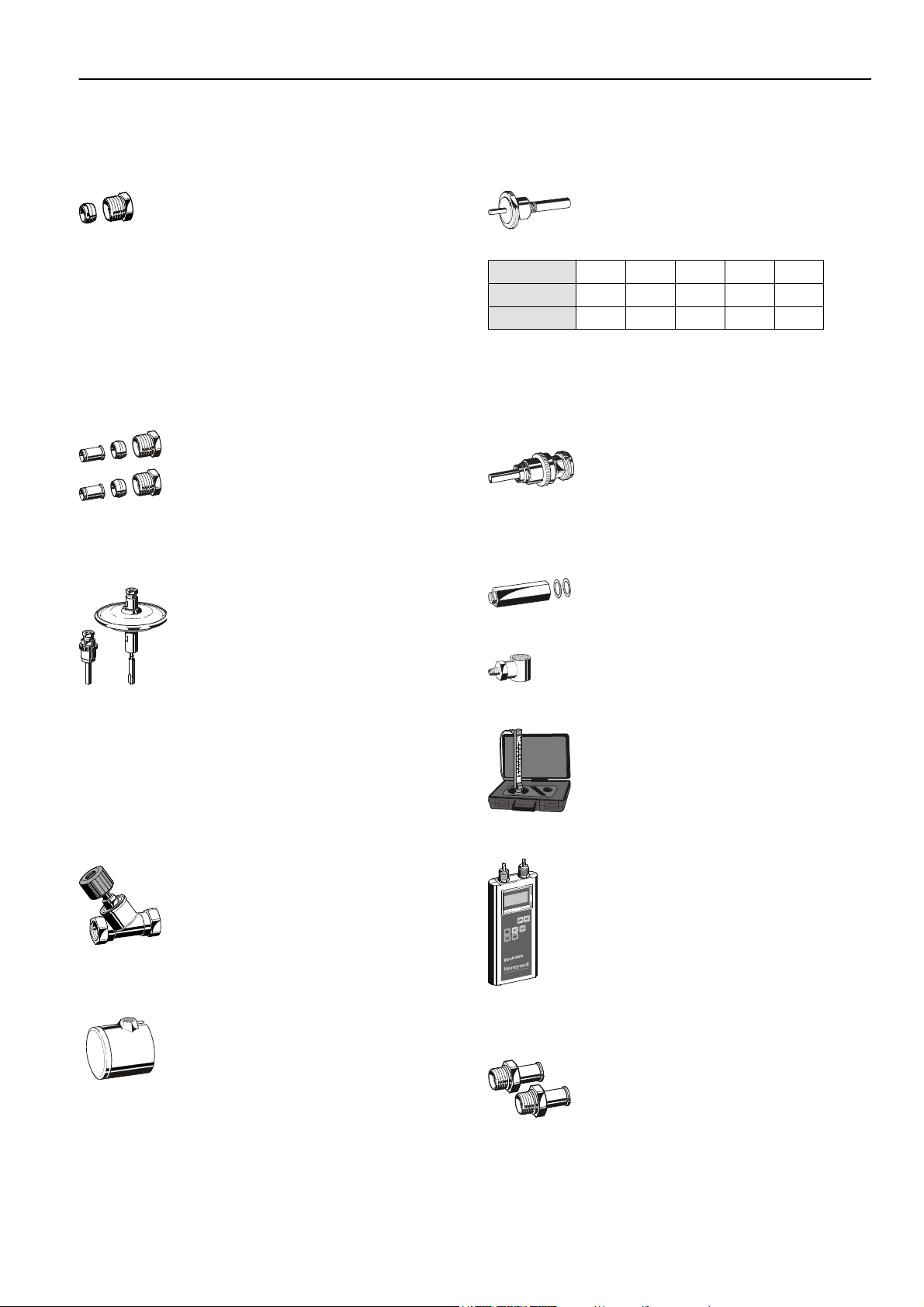
Accessories
Connections
Set of compression ring and nut
1/2” x 10 mm VA650A1210
1/2” x 12 mm VA650A1212
1/2” x 14 mm VA650A1214
1/2” x 15 mm VA650A1215
1/2” x 16 mm VA650A1216
3/4” x 18 mm VA650A2018
3/4” x 22 mm VA650A2022
NOTE: Support inserts have to be used for soft copper and
Set of compression ring, nut and support insert (2 pcs each)
Accessories
Kombi-DU Diaphragm Unit (V5012) for valves DN15...DN40
steel pipe (wall thickness 1 mm).
1/2” x 12 mm VA651A1212
1/2” x 15 mm VA651A1215
1/2” x 16 mm VA651A1216
3/4” x 18 mm VA651A2018
Setting range 0,1...0,3 bar
(1,45...4,35 psi) differential
pressure
Setting range 0,3...0,6 bar
(4,35...8,7 psi) differential
pressure
V5012A0103
V5012A0306
KOMBI-2-PLUS (V5032)
Adapter for actuators with M 30 x 1,5 connection
for valves DN15...DN40 VA2500A001
vs
-values for Kombi-2-plus with installed adapter:
k
DN
kvs-value
cv-value
NOTE: The Kombi-2-plus valve must be pre-set to 1.5 (for
DN15...25) or 1.0 (DN32...40) when used with actuator.
Pump pressure: max. 2 bar (29 psi)
Draining adapter
15 20 25 32 40
1,50 3,50 3,50 5,50 5,50
1,76 4,1 4,1 6,44 6,44
for all sizes VA3500A001
Measuring equipment
Extension piece for pressure test cocks, length 45 mm – for use with
insulated Kombi-2-plus
for all sizes VA2601A008
Measuring adapters (2 pcs)
for all sizes VS3600A008
NOTE: For product information and diagrams see product
data sheet ‘V5012 Kombi-DU’.
The Kombi-2-plus valve must be pre-set to 1.5 (for
DN15...25) or 1.0 (DN32...40) when used with the
Kombi-Diaphragm Unit.
Pump pressure: max. 2 bar (29 psi)
Kombi-3-plus BLACK (V5100) as shutoff valve and Kombi-DU connection point in the s upply
DN15 V5100Y0015
DN20 V5100Y0020
DN25 V5100Y0025
DN32 V5100Y0032
DN40 V5100Y0040
Tamper-proof cap
for valves DN15...DN25 VA2501A010
for valves DN32...DN50 VA2501A032
Flow meter
for all sizes VM200A1001
‘BasicMES’ handheld measuring computer
for all sizes; computer is supplied with case and accessories
Spare parts
Pressure test cocks (2 pcs)
for all sizes VA2600A008
VM241A1002
Honeywell AG • All rights reserved 3 EN0H-0048GE25 R0402
Page 4
KOMBI-2-PLUS (V5032)
P
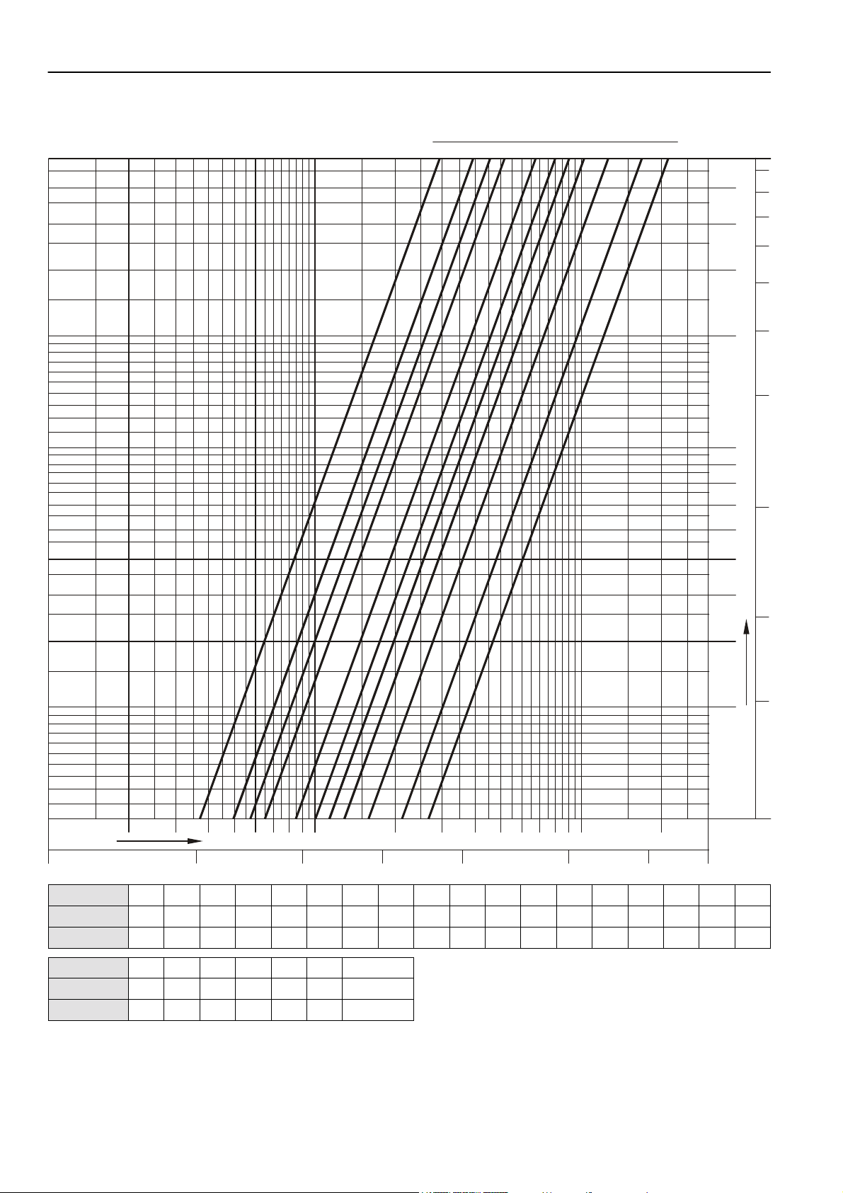
Flow Data DN15
0,3
0,6
0,8
re-setting
1,5 2
2,5
7
3,5
4
4,9
0
0
1
31
,
8
6
8
5
7
0
,
6
4
0
,
5
3
0
,
4
0
,
3
2
0
,
2
0
0
0
0
1
9
8
0
,
7
1
6
10 2
kg/h
Flow
Pre-setting
kv-value
cv-value
5
4
3
2
r
p
a
o
b
r
a
d
m
P
e
r
u
s
0
s
0
e
r
0
0
1
1
P
356781009245
4
0,025 0,050,0028 0,01 0,5l/sec
0,1
7 8 1000932
6
0,25
3
0,3 0,4 0,6 0,8 1,0 1,2 1,4 1,6 1,8 2,0 2,2 2,4 2,6 2,8 3,0 3,2 3,4 3,6
0,37 0,43 0,49 0,57 0,65 0,73 0,81 0,88 0,94 1,00 1,05 1,10 1,16 1,22 1,32 1,42 1,57 1,74
0,43 0,50 0,57 0,67 0,76 0,85 0,95 1,03 1,10 1,17 1,23 1,29 1,36 1,43 1,54 1,66 1,84 2,04
5
,
0
3
,
0
.
I
.
S
.
P
5
4
1
,
0
Pre-setting
kv-value
cv-value
3,8 4,0 4,2 4,4 4,6 4,8 4,9 = open
1,92 2,12 2,31 2,49 2,63 2,67 kvs = 2,70
2,25 2,48 2,70 2,91 3,08 3,12 3,16
NOTE: Flow diagram is ONLY valid for valve WITHOUT installed actuator (-adapter) or Kombi-Diaphragm Unit
EN0H-0048GE25 R0402 4 Honeywell AG • All rights reserved
Page 5

Flow Data DN20
P
0,3
0,6
0,8
KOMBI-2-PLUS (V5032)
re-setting
1,5
1
2,5 3
2
3,5
4
51,2 5,9
0
0
1
7
,
8
6
8
5
7
0
,
6
4
0
,
5
3
0
,
4
0
,
3
2
0
,
2
0
0
0
0
1
9
8
0
,
7
1
6
60 100
kg/h
Flow
l/sec
Pre-setting
kv-value
cv-value
5
4
3
2
r
p
a
o
b
r
a
d
m
P
e
r
u
s
0
s
0
e
r
0
0
1
1
P
2 4 5 6 7 8 100093 2 4 5 6 7 8 1000093
0,05
0,10,017
0,25
0,5
1,0
2,5
0,3 0,4 0,6 0,8 1,0 1,2 1,4 1,6 1,8 2,0 2,2 2,4 2,6 2,8 3,0 3,2 3,4 3,6
0,68 0,72 0,84 0,97 1,10 1,30 1,50 1,70 1,90 2,10 2,30 2,50 2,70 2,91 3,12 3,36 3,60 3,86
0,80 0,84 0,98 1,13 1,29 1,52 1,76 1,99 2,22 2,46 2,69 2,93 3,16 3,40 3,65 3,93 4,21 4,52
5
,
0
3
,
0
.
I
.
S
.
P
5
4
1
,
0
Pre-setting
kv-value
cv-value
3,8 4,0 4,2 4,4 4,6 4,8 5,0 5,2 5,4 5,6 5,8 5,9 = open
4,12 4,40 4,69 4,99 5,28 5,57 5,84 6,07 6,26 6,32 6,38 kvs = 6,40
4,82 5,15 5,49 5,84 6,18 6,52 6,83 7,10 7,32 7,39 7,46 7,49
NOTE: Flow diagram is ONLY valid for valve WITHOUT installed actuator (-adapter) or Kombi-Diaphragm Unit
Honeywell AG • All rights reserved 5 EN0H-0048GE25 R0402
Page 6

KOMBI-2-PLUS (V5032)
P
Flow Data DN25
0,3
0,6
0,8
re-setting
1,5
1
2,5 3
2
3,5
4
5,9
51,2
0
0
1
7
,
8
6
8
5
7
0
,
6
4
0
,
5
3
0
,
4
0
,
3
2
0
,
2
0
0
0
0
1
9
8
0
,
7
1
6
60 100
kg/h
Flow
l/sec
Pre-setting
kv-value
cv-value
5
4
3
2
r
p
a
o
b
r
a
d
m
P
e
r
u
s
0
s
0
e
r
0
0
1
1
P
2 4 5 6 7 8 100093 2 4 5 6 7 8 1000093
0,05
0,10,017
0,25
0,5
1,0
2,5
0,3 0,4 0,6 0,8 1,0 1,2 1,4 1,6 1,8 2,0 2,2 2,4 2,6 2,8 3,0 3,2 3,4 3,6
0,68 0,72 0,84 0,97 1,10 1,30 1,50 1,70 1,90 2,10 2,30 2,50 2,70 2,95 3,20 3,48 3,76 4,05
0,80 0,84 0,98 1,13 1,29 1,52 1,76 1,99 2,22 2,46 2,69 2,93 3,16 3,45 3,74 4,07 4,40 4,74
5
,
0
3
,
0
.
I
.
S
.
P
5
4
1
,
0
Pre-setting
kv-value
cv-value
3,8 4,0 4,2 4,4 4,6 4,8 5,0 5,2 5,4 5,6 5,8 5,9 = open
4,34 4,64 4,94 5,24 5,52 5,80 6,06 6,30 6,50 6,65 6,75 kvs = 6,80
5,08 5,43 5,78 6,13 6,46 6,79 7,09 7,37 7,61 7,78 7,90 7,96
NOTE: Flow diagram is ONLY valid for valve WITHOUT installed actuator (-adapter) or Kombi-Diaphragm Unit
EN0H-0048GE25 R0402 6 Honeywell AG • All rights reserved
Page 7

Flow Data DN32
P
0,5
KOMBI-2-PLUS (V5032)
re-setting
1
1,2
1,5 2
4
5
3
6,5
6
0
0
1
7
,
8
6
8
5
7
0
,
6
4
0
,
5
3
0
,
4
0
,
3
2
0
,
2
0
0
0
0
1
9
8
0
,
7
1
6
100 2
kg/h
Flow
Pre-setting
kv-value
cv-value
5
4
3
2
r
p
a
o
b
r
a
d
m
P
e
r
u
s
0
s
0
e
r
0
0
1
1
P
3 5 6 7 8 10009245
4
0,25 0,50,028 0,1 5,0l/sec
1,0
7 8 10000932
6
2,5
3
0,5 0,6 0,8 1,0 1,2 1,4 1,6 1,8 2,0 2,2 2,4 2,6 2,8 3,0 3,2 3,4 3,6 3,8
1,40 1,45 1,55 1,60 2,60 3,70 4,80 5,90 6,50 6,90 7,50 8,30 9,20 10,2 11,2 12,2 13,2 14,1
1,64 1,70 1,81 1,87 3,04 4,33 5,62 6,90 7,61 8,07 8,78 9,71 10,8 11,9 13,1 14,3 15,4 16,5
5
,
0
3
,
0
.
I
.
S
.
P
5
4
1
,
0
Pre-setting
kv-value
cv-value
4,0 4,2 4,4 4,6 4,8 5,0 5,2 5,4 5,6 5,8 6,0 6,2 6,4 6,5 = open
15,0 15,8 16,5 17,1 17,7 18,2 18,6 19,0 19,4 19,7 20,0 20,4 20,8 kvs = 21,0
17,6 18,5 19,3 20,0 20,7 21,3 21,8 22,2 22,7 23,0 23,4 23,9 24,3 24,6
NOTE: Flow diagram is ONLY valid for valve WITHOUT installed actuator (-adapter) or Kombi-Diaphragm Unit
Honeywell AG • All rights reserved 7 EN0H-0048GE25 R0402
Page 8

KOMBI-2-PLUS (V5032)
P
Flow Data DN40
re-setting
6
0,5 6,5
1
1,2
1,5 2
3
5
4
7
,
8
6
8
5
7
0
,
6
4
0
,
5
3
0
,
4
0
,
3
2
0
,
2
0
0
0
0
0
0
1
1
9
8
0
,
7
1
6
100 2
kg/h
Flow
Pre-setting
kv-value
cv-value
5
4
3
2
r
p
a
o
b
r
a
d
m
P
e
r
u
s
0
s
0
e
r
0
0
1
1
P
3 5 6 7 8 10009245
4
0,25 0,50,028 0,1 5,0l/sec
1,0
7 8 10000932
6
2,5
3
0,5 0,6 0,8 1,0 1,2 1,4 1,6 1,8 2,0 2,2 2,4 2,6 2,8 3,0 3,2 3,4 3,6 3,8
1,40 1,45 1,55 1,60 2,60 3,70 4,80 5,90 6,50 6,90 7,50 8,30 9,20 10,2 11,2 12,2 13,2 14,1
1,64 1,70 1,81 1,87 3,04 4,33 5,62 6,90 7,61 8,07 8,78 9,71 10,8 11,9 13,1 14,3 15,4 16,5
5
,
0
3
,
0
.
I
.
S
.
P
5
4
1
,
0
Pre-setting
kv-value
cv-value
4,0 4,2 4,4 4,6 4,8 5,0 5,2 5,4 5,6 5,8 6,0 6,2 6,4 6,5 = open
15,0 15,8 16,5 17,1 17,7 18,2 18,6 19,0 19,4 19,7 20,0 20,8 21,6 kvs = 22,0
17,6 18,5 19,3 20,0 20,7 21,3 21,8 22,2 22,7 23,0 23,4 24,3 25,3 25,7
NOTE: Flow diagram is ONLY valid for valve WITHOUT installed actuator (-adapter) or Kombi-Diaphragm Unit
EN0H-0048GE25 R0402 8 Honeywell AG • All rights reserved
Page 9

Flow Data DN50
P
KOMBI-2-PLUS (V5032)
re-setting
1
1,5
2
2,5 3
3,5
4
57
7,9
0
0
1
7
,
8
6
8
5
7
0
,
6
4
0
,
5
3
0
,
4
0
,
3
2
0
,
2
0
0
0
0
1
9
8
0
,
7
1
6
100
Flow
Pre-setting
kv-value
cv-value
5
4
3
2
r
p
a
o
b
r
a
d
P
m
e
r
u
s
0
s
0
e
r
0
0
1
1
P
4kg/h
2
3 5 6 7 8 10009 2 4 5 6 7 8 10000932
0,25
0,50,028 0,1 5,0l/sec
1,0
2,5
3
1,0 1,2 1,4 1,6 1,8 2,0 2,2 2,4 2,6 2,8 3,0 3,2 3,4 3,6 3,8 4,0 4,2 4,4
0,80 1,25 1,88 2,72 3,78 5,10 6,68 8,54 10,7 13,0 15,6 18,7 21,0 22,8 24,3 25,4 26,4 27,2
0,94 1,46 2,20 3,18 4,42 5,97 7,82 9,99 12,5 15,2 18,3 21,9 24,6 26,7 28,4 29,7 30,9 31,8
5
,
0
3
,
0
.
I
.
S
.
P
5
4
1
,
0
Pre-setting
kv-value
cv-value
4,6 4,8 5,0 5,2 5,4 5,6 5,8 6,0 6,2 6,4 6,6 6,8 7,0 7,2 7,4 7,6 7,9 = open
28,0 28,8 29,5 30,2 31,0 31,7 32,4 33,0 33,6 34,1 34,6 35,0 35,4 35,8 36,2 36,8 kvs = 38,0
32,8 33,7 34,5 35,3 36,3 37,1 37,9 38,6 39,3 39,9 40,5 41,0 41,4 41,9 42,4 43,1 44,5
Honeywell AG • All rights reserved 9 EN0H-0048GE25 R0402
Page 10

KOMBI-2-PLUS (V5032)
P
Flow Data DN65
re-setting
1,5 2 3 41
5
67,9
0
0
1
7
,
8
6
8
5
7
0
,
6
4
0
,
5
3
0
,
4
0
,
3
2
0
,
2
0
0
0
0
1
9
8
0
,
7
1
6
100
kg/h
Flow
Pre-setting
kv-value
cv-value
5
4
3
2
r
a
b
m
0
1
3 2 4 5 6 7 8 100009324563
2 4 5 6 7 8 1000
9
0,25 0,50,028 0,1 5,0l/sec
1,0
2,5
10,0
1,0 1,2 1,4 1,6 1,8 2,0 2,2 2,4 2,6 2,8 3,0 3,2 3,4 3,6 3,8 4,0 4,2 4,4
1,40 1,50 2,50 3,50 4,50 5,50 7,70 10,0 12,2 14,5 16,7 19,0 21,3 23,7 26,0 28,3 30,1 31,9
1,64 1,76 2,93 4,10 5,27 6,44 9,01 11,7 14,3 17,0 19,5 22,2 24,9 27,7 30,4 33,1 35,2 37,3
5
,
0
3
,
0
.
I
p
.
o
S
r
a
.
d
P
P
e
r
u
s
5
0
s
4
0
e
1
r
,
0
0
1
P
Pre-setting
kv-value
cv-value
4,6 4,8 5,0 5,2 5,4 5,6 5,8 6,0 6,2 6,4 6,6 6,8 7,0 7,2 7,4 7,6 7,9 = open
33,6 35,4 37,2 38,6 40,1 41,5 43,0 44,0 44,9 45,4 46,0 46,5 47,0 47,1 47,3 47,4 kvs = 47,7
39,3 41,4 43,5 45,2 46,9 48,6 50,3 51,5 52,5 53,1 53,8 54,4 55,0 55,0 55,3 55,5 55,8
EN0H-0048GE25 R0402 10 Honeywell AG • All rights reserved
Page 11

Flow Data DN80
P
KOMBI-2-PLUS (V5032)
re-setting
1,5 2 3 41
56 7,97
0
0
1
7
,
8
6
8
5
7
0
,
6
4
0
,
5
3
0
,
4
0
,
3
2
0
,
2
0
0
0
0
1
9
8
0
,
7
1
6
100
kg/h
Flow
Pre-setting
kv-value
kv-value
5
4
3
2
r
a
b
m
0
1
3 2 4 5 6 7 8 100009324563
2 4 5 6 7 8 1000
9
0,25 0,50,028 0,1 5,0l/sec
1,0
2,5
10,0
1,0 1,2 1,4 1,6 1,8 2,0 2,2 2,4 2,6 2,8 3,0 3,2 3,4 3,6 3,8 4,0 4,2 4,4
2,20 4,20 6,20 8,10 10,1 12,1 15,3 18,5 21,6 24,8 28,0 30,9 33,9 36,8 39,8 42,7 44,9 47,0
2,57 4,91 7,25 9,48 11,8 14,2 17,9 21,6 25,3 29,0 32,8 36,1 39,7 43,1 46,6 50,0 52,5 55,0
5
,
0
3
,
0
.
I
p
.
o
S
r
a
.
d
P
P
e
r
u
s
5
0
s
4
0
e
1
r
,
0
0
1
P
Pre-setting
kv-value
kv-value
4,6 4,8 5,0 5,2 5,4 5,6 5,8 6,0 6,2 6,4 6,6 6,8 7,0 7,2 7,4 7,6 7,9 = open
49,2 51,3 53,5 55,2 57,0 58,7 60,5 62,2 63,4 64,5 65,7 66,8 68,0 68,6 69,2 69,8 kvs = 71,0
57,6 60,0 62,6 64,6 66,7 68,7 70,8 72,8 74,2 75,5 76,9 78,2 79,6 80,3 81,0 81,7 83,1
Honeywell AG • All rights reserved 11 EN0H-0048GE25 R0402
Page 12

KOMBI-2-PLUS (V5032)
Influence of Coolants on Fl ow Va lue s
The flow through a valve is defined by the kv-value. The kv-value is the flow m through a valve in [m³/h] at a differential pressure
of 1 bar (14,5 psi) and is only valid for fluids with a density of σ0 = 1000 kg/m³. This condition is met by water at a temperature of
20°C (68°F). For fluids with another density the following formula can be applied:
Kv
Medium
m
=
p
∆
ρ
Medium
×
ρ
0
Correction Factor f
When the density σ is expressed in t/m³ instead of kg/m³ the correction factor f is the result. The correction factor f can be used
to re-calculate kv-value, pressure drop and flow:
KvKv
Medium
Medium
Normal water 100% 1,000 0,998 0,994 0,988 0,981 0,972
Ethylen glycol 70% 1,052 1,047 1,041 1,033 1,024 1,015
e.g. Antifrogen N 50% 1,086 1,079 1,070 1,061 1,052 1,042
Propylen glycol 70% 1,035 1,029 1,021 1,012 1,002 0,991
e.g. Antifrogen L 50% 1,053 1,044 1,035 1,025 1,014 1,002
0
f
Table 1. Values for correction factor f
water part 5°C (41°F) 20°C (68°F) 35°C (95°F) 50°C (122°F) 65°C (149°F) 80°C (176°F)
Medium
fpp
×∆=∆
0
Correction factor f
Medium
mm
1
×=
1
×=
0
f
Control Products
Honeywell AG Phone: (49) 2932 9880
Zu den Ruhrwiesen 3 Fax: (49) 2932 988239
D-59755 Arnsberg-Neheim mng@honeywell.com http://europe.hbc.honeywell.com
EN0H-0048GE25 R0402 12 Subject to change • All rights reserved
 Loading...