

Page 1
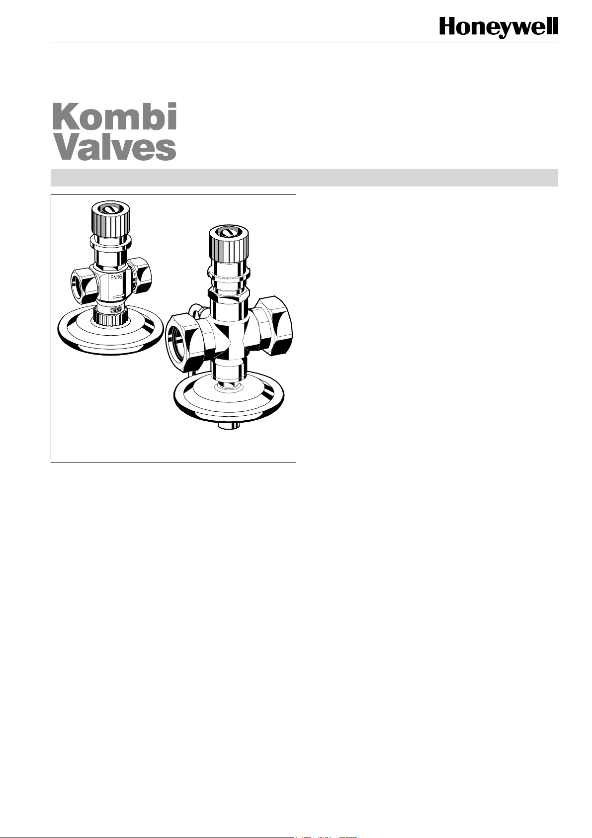
Kombi-FC, DN 15
Kombi-FC, DN 25
and DN 40
V5015
Kombi-FC
FLOW CONTROLLER
PRODUCT DATA
Application
Kombi-FC flow controllers are installed in the return of systems with constant volume flows, for example one-pipe systems. They support a hydronic balance by keeping the flow
through consumers at a constant pre-set level even under
changing pressure conditions.
Apart from flow control the Kombi-FC also provides shutoff
and draining functions (see ‘Accessories’). The compact body
design allows installation under restricted space conditions.
Features
• Automatic flow control, infinitely pre-settable up to
000 kg/h
1
• Easy pre-setting of the flow without pipe system cal-
culation
• Leaden sealing of pre-setting possible
• Additional functions shutoff and draining
• Compact design
• Robust, low-noise and flow efficient valve housing
made of corrosion-resistant red bronze
Specifications
Design
The Kombi-FC is made up of:
• Valve housing PN16, DN15, DN25 and DN40 with connection threads, flat sealing. Refer to ‘Accessories’ for
suitable pipe connections
• Valve insert
• Diaphragm unit
• Handwheel
• Union-nuts with sealings
Medium
pH-value
Operating temperature
Operating pressure
Min. differential pressure
Max. differential pressure
Max. Flow
Water or water-glycol mixture
8...9,5
2...130°C (36...266°F)
max. 16 bar (232 psi)
0,2 bar (2,9 psi),
recommended value also see
diagram ‘Flow Characteristic’
2 bar (29 psi)
DN15 1000 kg/h
DN25 2000 kg/h
DN40 4000 kg/h
Materials
• Valve housing made of red bronze
• Valve insert made of brass with EPDM O-rings and soft
sealings
• Diaphragm housing made of stainless steel with membrane made of EPDM
• Handwheel made of blue plastic
• Union-nuts made of nickel-plated brass with EPDM seal-
ings
Copyright © 2002 Honeywell AG • All rights reserved EN0H-0205GE25 R0902
Function
The Kombi-FC control valve is a proportional controller without need of auxiliary energy. Thereby the pressure sensing is
done before and after a throttle, which is adjusted by the
handwheel. At version DN 15 pressure sensing is done internally. At versions DN 25 and DN 40 pressure sensing is done
before the throttle by using pipes or tubes for pressure sensing. Pressure sensing after the throttle is done internally.
The flow is controlled by the differential pressure over the
throttle and kept to a constant, pre-set value.
Page 2
KOMBI-FC (V5015)
r
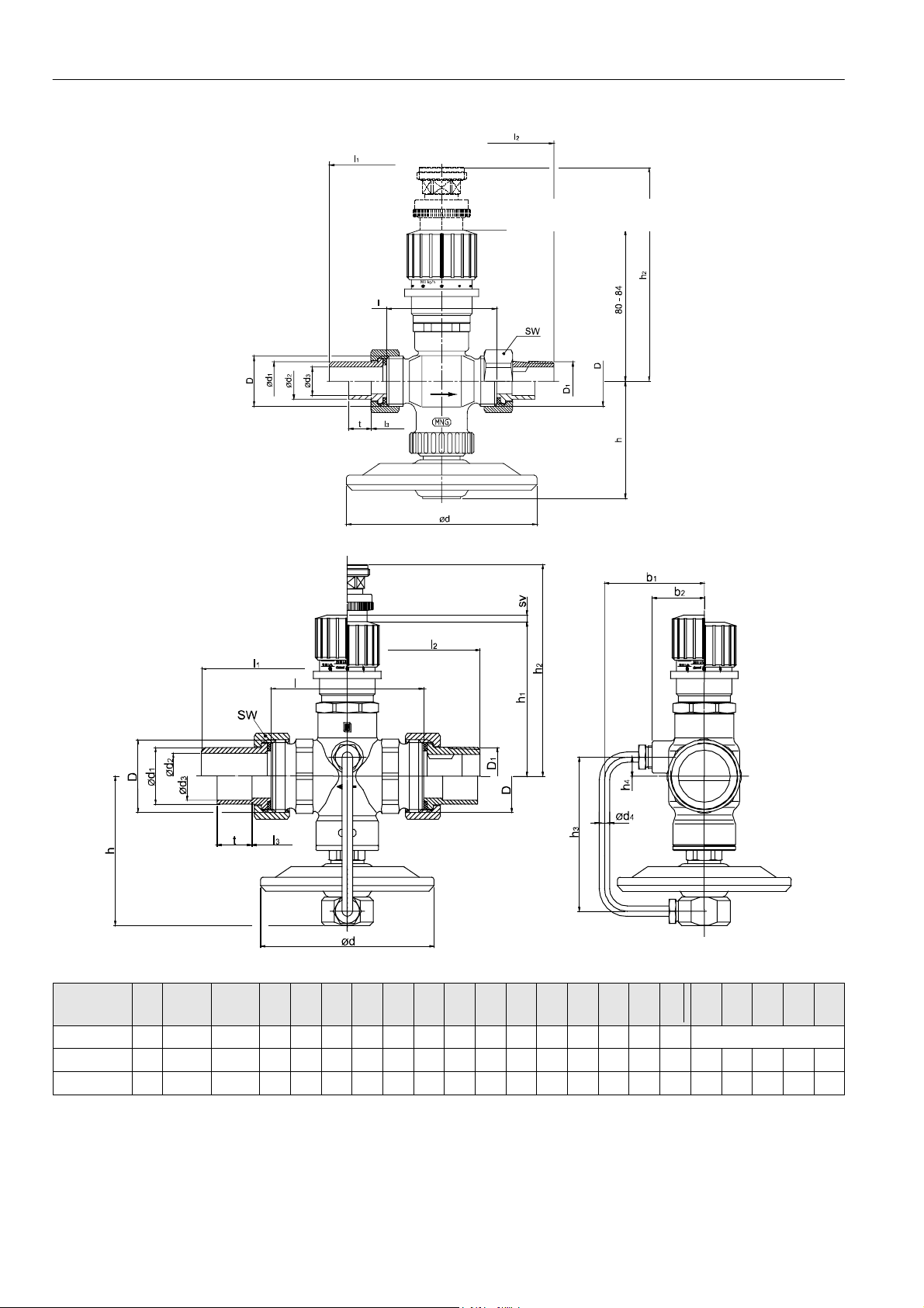
Dimensions
Installed draining adapte
Fig. 1 Dimensions DN15
Fig. 2. Dimensions DN25 and DN40
OS-No. DN D
DIN ISO 228D1DIN 2999
V5015X0015 15 G 3/4 R 1/2 100 20,5 19 15 58 118 118 74 12 30 62 80 116 4 Pressure pipe is installed
V5015X0025 25 G 1 1/4 R 1 100 33 26,4 28 88 168 153 110 20 46 86 89 122 4 6 89 11 58 30
V5015X0040 40 G 1 3/4 R 1 1/2 100 47,5 41 42 113 215 233 135 29 60 88 93 126 7 6 101 21 58 37
NOTE: All dimensions in mm unless otherwise stated.
NOTE: Draining adapters and tailpieces are not supplied with the valve.
EN0H-0205GE25 R0902 2 Honeywell AG • All rights reserved
Ød Ød1 Ød2 Ød3 l l1 l2 l3 t SW h h1 h2 SV Ød4 h3 h4 b1 b2
Page 3

Ordering Information
Order text DN Max. Flow kvs (cv)-value OS-No.
Kombi-FC Flow Controller
Application Examples
KOMBI-FC (V5015)
15 1000 kg/h 2,5 (2,93) V5015X0015
25 2000 kg/h 5,0 (5,85) V5015X0025
40 4000 kg/h 10,0 (11,70) V5015X0040
Fig. 2 Kombi-FC maintains constant flow in single pipe
cooling and heating circuits
Fig. 3. Kombi-FC fitted as a flow rate regulator on fan coil
units
Please Note
• To avoid stone deposit and corrosion the composition of the medium should conform with VDI-Guideline 2035.
• Additives have to be suitalbe for EPDM sealings.
• Mineral oil or any products with mineral oil content in the medium result in heavy swelling and, in most cases, failure of
EPDM sealings.
• System has to be flushed thoroughly before initial operation.
• No complaints or costs resulting from non-compliance with above rules will be accepted by Honeywell.
• Please contact us if you should have any special requirements or needs.
Honeywell AG • All rights reserved 3 EN0H-0205GE25 R0902
Page 4

KOMBI-FC (V5015)
Accessories
Brass soldering tailpiece, flat sealing
15 mm, for valves DN15
28 mm, for valves DN25
42 mm, for valves DN40
Steel welding tailpiece, flat sealing
1/2", for valves DN15
1", for valves DN25
1 1/2", for valves DN40
Externally threaded brass tailpiece, flat sealing
1/2", for valves DN15
1", for valves DN25
1 1/2", for valves DN40
Reducing soldering tailpiece
Valve DN25 on copper pipe
22 mm
Valve DN40 on copper pipe
28 mm
Reducing welding tailpiece
Valve DN25 on pipe DN20
Ventil DN40 on pipe DN32
VA5530A015
VA5530A025
VA5530A040
VA5540A015
VA5540A025
VA5540A040
VA5500A015
VA5500A025
VA5500A040
VA5512A020
VA5512A032
VA5511A020
VA5511A032
Draining adapter
VA3500A001
Kombi-3-plus RED (
supply
NOTE: Also see Product Data 'Kombi-3-plus'.
Kombi-3-plus BLACK (V5100) shutoff valve for the supply
NOTE: Also see Product Data 'Kombi-3-plus'.
V5000) measuring and shutoff valve for the
DN15
DN20
DN25
DN32
DN40
DN15
DN20
DN25
DN32
DN40
V5000X0015
V5000X0020
V5000X0025
V5000X0032
V5000X0040
V5100X0015
V5100X0020
V5100X0025
V5100X0032
V5100X0040
Reducing externally threaded tailpiece
Valve DN25 on thread
connection 3/4“
Valve DN40 on thread
connection 1 1/4“
Adapter with union-nut and sealing
For extension valve DN15 on
connection DN20
For extension valve DN25 on
connection DN32
NOTE: Suitable union tailpieces see above.
VA5510A020
VA5510A032
VA2101A020
VA2101A032
'Stop-Ball' ball valve for the supply
DN15
DN20
DN25
DN32
DN40
NOTE: Also see Product Data 'VB550 - Stop-Ball'.
VB550X0015
VB550X0020
VB550X0025
VB550X0032
VB550X0040
EN0H-0205GE25 R0902 4 Honeywell AG • All rights reserved
Page 5

Flow Characteristic
KOMBI-FC (V5015)
Method of Calculation
Given:
Kombi-3-Plus BLACK in the supply and Kombi-FC in the return
Mass flow in circuit: q
Available differential pressure of circuit: ∆p
Required differential pressure of circuit: ∆p
Required:
Dimension Kombi-FC
Differential pressure Kombi-FC
Result:
The nominal size DN25 of valve is choosen dependent on mass flow q
Kombi-FC is set to 1200 kg/h.
Calculation of the differential pressure:
Differential pressure Kombi-3-Plus BLACK, DN25 ∆p
Differential pressure Kombi-FC ∆p
Required differential pressure ∆p
= 271 mbar for Kombi-FC depending to given mass flow qm = 1200 kg/h is within the recom-
v2
mended range of application.
Honeywell AG • All rights reserved 5 EN0H-0205GE25 R0902
= 1200 kg/h
m
= 400 mbar
0
= 100 mbar
v1
= 1200 kg/h in flow characteristic
m
= 29 mbar
v1
= ∆p0 – (∆pv1 + ∆pv1)
v2
= 400 – (29 + 100) mbar
= 271 mbar
Page 6

KOMBI-FC (V5015)
Automation & Control Products
Honeywell AG Phone: (49) 2932 9880
Zu den Ruhrwiesen 3 Fax: (49) 2932 988239
D-59755 Arnsberg-Neheim mng@honeywell.com http://europe.hbc.honeywell.com
EN0H-0205GE25 R0902 6 Subject to change • All rights reserved
 Loading...