

Page 1

TST... and TST...-R
p
Smart Tem
ELEC. TEMPERATURE SWITCHES/TRANSMITTERS
GENERAL INFORMATION
Honeywell FEMA's TST and TST...R series thermostats
require adjustment (configuration and parameterization) in
only two modes (the basic mode and the expert mode) and
are suitable for the precision-adjustment and monitoring of
medium temperatures in the fields of plant construction,
fluidics, process technology, and pneumatics, as well as in
the monitoring and control of furnaces, heating units, and
process temperatures, as well as for applications in the
field of frost protection.
These thermostats provide sufficient accuracy (0.5% of the
final value) for measurement monitoring in many laboratory
applications. Models with built-on sensors for a temperature range of -50...+200 °C and models with an external sensor for a temperature range of -50...+400 °C are
available. Customized PT1000 precision class-A sensors
(conforming to DIN 60 751) can also be employed in the
aforementioned temperature ranges.
INSTALLATION INSTRUCTIONS
TECHNICAL DATA
Housing polybutylene terephthalate
Ambient temperature -20...+60 °C
Storage temperature -35...+80 °C
Temp. of medium -50...+50 °C, -50...200 °C,
Relative humidity 0...95%, non-condensing
Accuracy, total 0.5% of FSO (full-scale output)
Medium temp. drift 0.3% / 10 K
Parts in contact with medium
Process connections G½" external thread
Electrical connection
Both series 2 5-prong A-coded M12 plugs
TST...-R series additional 3-prong B-coded
Protection class II as per EN 60335-1 (when
Protection rating IP65 as per EN 60529
Climate class C as per DIN EN 60654
Power supply 14...36 Vdc (> 50 °C,
EMC as per EN 61326/A1
Switch outputs configurable as N.O./N.C.
Switching difference (SP and RP) configurable
Relay output (TST..-R-Version)
Contact type 1 switch-over contact
Min. electrical lifetime 250,000 switching cycles
Switching performance, gold (AgSnO
AC1 (resistive) 1.5 VA (24 Vdc / 60 mA,
AC15 (inductive) unsuitable
Max. switch-on current 60 mA for < 5 ms
Min. switching performance 50 mW (> 5 V or > 2 mA)
Switching performance, silver (AgSnO
AC1 (resistive) 690 VA (230 Vac / 3 A)
AC15 (inductive) 230 VA (230 Vac / 1 A)
Max. switch-on current 30 A for < 5 ms
Min. switching performance 500 mW (> 12 V or
Diagnostic output (warning output on plug 2)
Max. load 20 mA / 14...36 Vdc
Transmitter output (analog output)
Voltage/current 0...10 V / 4...20 mA or
Transient response approx. 300 ms
-50...+400 °C (dependent on
model)
as per DIN IEC 60947-5-2
M12 plug as per DIN EN
50044
installed accordingly)
max. 30 Vdc), max. 100 mA
high-side/low-side or as pushpull / inverted push-pull
switches
max. 250 mA / 14...36 Vdc
+Au) contacts
2
230 Vac / 6.5 mA)
) contacts
2
(for cos φ < 0.7: 10 A)
> 10 mA)
10...0 V / 20...4 mA
(config. in expert mode)
® U.S. Registered Trademark
Copyright © 2003 Honeywell Inc. MU1B-0248GE51 R0903
All Rights Reserved 7157 672
Page 2
TST... AND TST...-R ELECTRONIC TEMPERATURE SWITCHES/TRANSMITTERS
A
A
SERIES
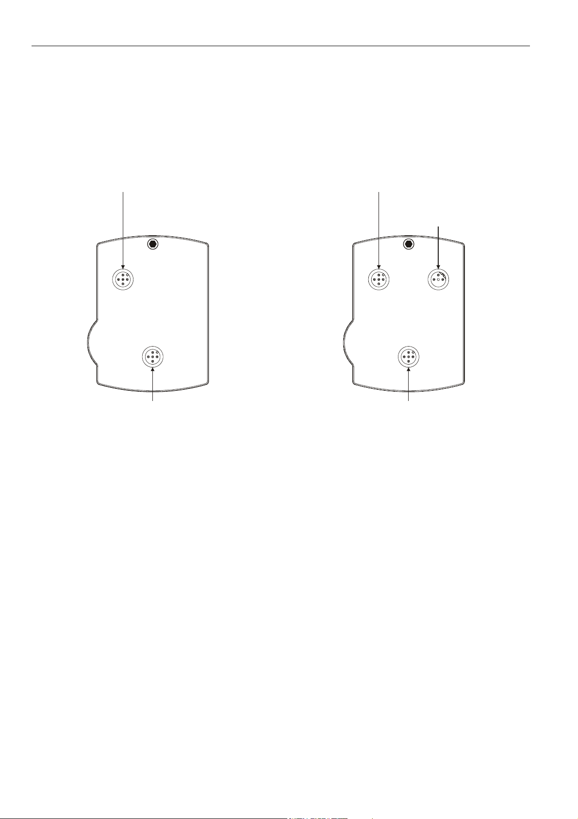
The electronic temperature switches/transmitters are available in two series, TST... and TST...-R, easily distinguishable by the
number of M12 plugs present on the rear side.
TST... Series
The devices of this series provide both switching and
transmitting functionality.
plug 2:
power supply,
OUT, and WARN
plug 1:
power supply,
OUT1, and OUT2
Fig. 1. TST... Series, rear view of housing
TST...-R Series
Like TST... Series devices, the devices of this series provide
switching and transmitting, but also relaying functionality.
plug 2:
power supply,
OUT, and WARN
plug 3:
switch-over
contact relay
plug 1:
power supply,
OUT1, and OUT2
Fig. 2. TST...-R Series, rear view of housing
Two switching outputs (OUT1 and OUT2) are located on a 5prong, A-coded (as per DIN IEC 60947-5-2) M12 plug (plug
1), which you can also use to connect the power supply. You
can configure the two switching outputs as normally-open /
normally-closed high-side/low-side or push-pull / inverted
push-pull switches (see also Table 3 on page 8).
An analog output (AOUT) and a warning output (WARN) are
likewise located on a 5-prong, A-coded (as per DIN IEC
60947-5-2) M12 plug (plug 2), which you can also use to connect the power supply. You can configure the analog output
as either a 0...10 V / 10...0 V analog output or as a 4...20 mA
/ 20...4 mA analog output. The warning output provides feedback about the device's error status (see also section "Technical Data on the WARN Output" on page 6 and section
"Error Codes" on page 8).
A switch-over contact relay output is located on a 3-prong, Bcoded M12 plug (plug 3), for which a 4-prong M12 angle
junction box with pre-attached cable is available as an
accessory. You can configure this relay output to be coupled
with either OUT1 or OUT2 or with the warning output. If you
configure OUT2 as a warning output, the relay output will
then likewise function as a warning output (see also section
"Pin Assignment of Plug 3" on page 4). You cannot configure
the relay output as a normally-open or normally-closed
switch.
MU1B-0248GE51 R0903 2
Page 3

TST... AND TST...-R ELECTRONIC TEMPERATURE SWITCHES/TRANSMITTERS
IMPORTANT
The switching performance of the gold (AgSn0
µ
m]) switch-over contacts of the relay located on plug 3
must not be exceeded insofar as doing so will degrade
the contacts, making them unusable for the specified min.
switching performance; thereafter, the switching performance for silver (AgSnO
Da" on page 1) will apply.
) contacts (see "Technical
2
+Au [5
2
Temperature Ranges
For both series, versions of these devices are available for
the following temperature ranges (see Table 7 on page 19).
• devices with built-on sensor: -50...+50 °C,
• devices with built-on sensor and neck tube:
-50...+200 °C,
• devices with external sensor: -50...+200 °C and
-50...+400 °C.
BEFORE INSTALLATION
IMPORTANT
Installation is to be performed only by qualified personnel.
IMPORTANT
In order to comply with protection rating IP65, unused
M12 plugs must be capped (using the caps available as
accessories). The caps included in the shipment provide
protection against contamination during transportation,
only.
IMPORTANT
Regardless of the current operating mode (basic mode /
expert mode), all changes to output values take effect
immediately (except when OUT1[2] is configured as a
N.O./N.C. high-side/low-side or push-pull / inverted pushpull switch, in which case changes take effect only after
the EDIT symbol has been extinguished). However, they
will be stored permanently only if confirmed (via SAVE).
CAUTION
To avoid electrical shock or damage to the device,
you must ensure that all of the device's connections
are without voltage before attempting to detach plugs
and cables.
Before installing the device and connecting the wiring, check
to ensure that you are installing the proper device version.
See section "Manufacturer's Plate" on page 6).
Thermostats equipped with an external sensor (TST...EPT...)
are secured to a wall or wiring box by means of a retainer
(see Fig. 69 on page 18).
External sensors (P2-TVS...) are screwed directly into the
pipe via a G½" process connection. Using the M8 plug accompanying the shipment, they are then connected electrically to the TST200E... or TST400E... thermostats via a
sensor cable.
IMPORTANT
In order to avoid damage, never attempt to fasten the
device by rotating the housing. Mount the process connection using a suitable hexagonal wrench. Mounting is to
be performed by skilled personnel, only! The cable length
must not exceed 3 m. Use only PT1000-A sensors; otherwise, the specified accuracy of 0.5% for the entire device
cannot be guaranteed. The devices can be mounted in
any orientation desired, however, for optimal legibility of
the display, it is recommended that they be mounted in a
vertical orientation. For optimal legibility of the display,
but also to allow for more-flexible installation, the housing
can be rotated on the sensor by approx. 320°.
Electrical Connection
All wiring must comply with applicable electrical codes and
local ordinances (e.g. in Germany, in accordance with VDE
regulations). To prevent damage to the device, the voltage at
OUT1[2] must not exceed 36 Vdc. Refer to job or manufacturer's drawings for details.
IMPORTANT
In order to comply with protection class II, the auxiliary
power source must be reliably separated from the network power supply circuits as per DIN VDE 0106, part
101. When correspondingly installed, the device complies
with protection class II.
The connections for plugs 1 and 2 are protected against
short-circuiting and incorrect polarity.
NOTE: No tampering with the device is allowed. Opening
the device will invalidate the warranty.
NOTE: The devices must always be provided with power
via either plug 1 and/or plug 2. It is sufficient to
connect the power supply via one of these two
plugs. However, in the event that power is
supplied via both of these plugs, it must have the
same polarity and potential.
INSTALLATION
Dimensions
The housing (without process connection or plugs) has
dimensions of 98 x 70 x 60 mm. The overall dimensions
depend upon the number of plugs/cables and the sensor
type. See also Fig. 72 on page 23.
Mounting and Orientation
Thermostats equipped with a built-on sensor
(TST050...0200...) are screwed directly into the pipe via a
G½" process connection.
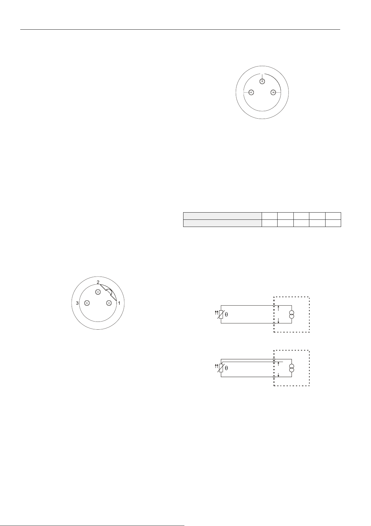
Pin Assignment of Plug 1
All versions of both series come equipped with plug 1, an Acoded, five-prong M12 plug (see Fig. 3).
Fig. 3. A-coded M12 plug
MU1B-0248GE51 R09033
Page 4
TST... AND TST...-R ELECTRONIC TEMPERATURE SWITCHES/TRANSMITTERS
Plug 1 has the following pin assignment:
1. Power supply (14...36 Vdc)
2. OUT2: an open-collector output which can be configured
as an N.O./N.C. high-side/low-side or as a push-pull /
inverted push-pull switch (see also Table 3 on page 8).
3. 0 volt
4. OUT1: an open-collector output which can be configured
as an N.O./N.C. high-side/low-side or as a push-pull /
inverted push-pull switch (see also Table 3 on page 8).
5. Programming interface
NOTE: The voltage provided by OUT1[2] can be as much
as 2.5 V lower than the device's power supply.
Thus, assuming a power supply voltage of e.g.
14 V and that the voltage at OUT1[2] is logical
"high," then: 14 V ≥ "high" ≥ 11.5 V. Assuming that
the voltage is logical "low," then: 2.5 V ≥ "low" ≥
0 V.
Pin Assignment of Plug 2
All versions of both series come equipped with plug 2, an Acoded, 5-prong M12 plug (see Fig. 3).
Plug 2 has the following pin assignment:
1. Power supply (14...36 Vdc)
2. WARN ("WARN" output; max. current load: 20 mA)
3. 0 volt
4. AOUT (which can be configured as a 0...10 V / 10...0 V
output or as a 4...20 mA / 20...4 mA output, max. R
when configured as a current output = 500 Ω)
5. Programming interface
L
Pin Assignment of Plug 3
All versions of the PST...-R series come equipped with plug
3, a B-coded, three-prong M12 plug (see Fig. 4).
Connecting the Sensor
Each sensor is equipped with a 3-prong M8 plug (see Fig. 5).
4
1
Fig. 5. Pin assignment of the sensor's M8 plug
In the event that you would like to connect a two-wire PT1000
sensor to the device (see Fig. 6), you must (in the expert
mode) correspondingly configure the device.
If you choose to use a two-wire sensor connection, you must
take into account that the fact that the device does not automatically compensate for the wire resistance; rather, the wire
resistance will fully affect the measuring results (see Table 1
for information on the resistance given a 10-meter-long [both
ways] connection wire made of copper).
Table 1. Cross-section and resistance of conductor
wire cross-section (mm2)
wire resistance (Ω)
However, it is possible to adjust the device in order to compensate for this resistance (see section "Balancing the
Device" on page 14). The temperature can thus be balanced
within a range of ±5 °C.
An additional option is to employ a three-wire sensor connection (see Fig. 7). However, the prerequisite for this is that
all three lines have identical properties and be exposed to the
same temperatures.
3
0.14 0.22 0.5 0.75 1.5
2.55 1.62 0.71 0.48 0.24
Fig. 4. B-coded M12 plug
NOTE: If inductive components are to be connected to the
switch-over contact relay, it must be prevented
from causing harmful interference or over-voltage.
Plug 3 has the following pin assignment:
1. common
2. N.C. (normally-closed)
3. N.O. (normally-open)
NOTE: The cable for connecting the relay is available as
an accessory. Its green/yellow grounding terminal
(PE) is not connected to the device (protection
class II).
MU1B-0248GE51 R0903 4
3
PT1000
U
1
Fig. 6. Two-wire configuration
4
PT1000
3
U
1
Fig. 7. Three-wire configuration
Page 5
TST... AND TST...-R ELECTRONIC TEMPERATURE SWITCHES/TRANSMITTERS
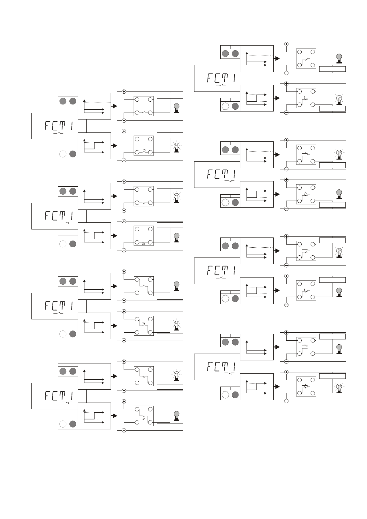
Technical Data on OUT1 and OUT2
• Max. current load per output: 250 mA.
• At the switch output, the voltage can diminish by as
much as 2.5 V.
Example software configurations for e.g. OUT 1 are
presented in Fig. 8 through Fig. 15.
greengreen
21
EXPERT
ZERO
greenorange
21
ON
OFF
ON
OFF
OUT1
OUT1
SP/RP
P
P
Fig. 8. OUT1 as a normally-open low-side switch
greengreen
21
EXPERT
ZERO
greenorange
21
ON
OFF
ON
OFF
OUT1
OUT1
SP/RP
P
P
Fig. 9. OUT1 as a normally-closed low-side switch
greengreen
21
EXPERT
ON
OFF
OUT1
P
plug 1
1 2
3 4
plug 1
1 2
3 4
plug 1
1 2
3 4
plug 1
1 2
3 4
plug 1
314
(max. 250 mA)
OUT1
(max. 250 mA)
OUT1
(max. 250 mA)
OUT1
(max. 250 mA)
OUT1
2
OUT1
(max. 250 mA)
load
load
load
load
load
EXPERT
ZERO
FSO
greengreen
21
greenorange
21
ON
OFF
ON
OFF
OUT1
OUT1
SP/RP
P
P
plug 1
1 2
3 4
plug 1
1 2
3 4
OUT1
load
(max. 250 mA)
OUT1
load
(max. 250 mA)
Fig. 12. OUT1 as a push-pull switch with load connected
to 0 V
EXPERT
ZERO
FSO
greengreen
21
greenorange
21
ON
OFF
ON
OFF
OUT1
OUT1
SP/RP
P
P
plug 1
1 2
3 4
plug 1
1 2
3 4
OUT1
load
(max. 250 mA)
OUT1
load
(max. 250 mA)
Fig. 13. OUT1 as an inverted push-pull switch with load
connected to 0 V
load
(max. 250 mA)
OUT1
load
(max. 250 mA)
OUT1
EXPERT
ZERO
FSO
greengreen
21
greenorange
21
ON
OFF
ON
OFF
OUT1
OUT1
SP/RP
P
P
plug 1
1 2
3 4
plug 1
1 2
3 4
FSO
OUT1
ON
greenorange
OFF
21
SP/RP
P
plug 1
2
314
Fig. 10. OUT1 as a normally-open high-side switch
EXPERT
FSO
greengreen
21
greenorange
21
ON
OFF
ON
OFF
OUT1
OUT1
SP/RP
P
P
plug 1
2
314
plug 1
2
314
Fig. 11. OUT1 as a normally-closed high-side switch
OUT1
load
(max. 250 mA)
OUT1
load
(max. 250 mA)
OUT1
load
(max. 250 mA)
Fig. 14. OUT1 as a push-pull switch with load connected
to the power supply
load
(max. 250 mA)
OUT1
load
(max. 250 mA)
OUT1
EXPERT
ZERO
FSO
greengreen
21
greenorange
21
ON
OFF
ON
OFF
OUT1
OUT1
SP/RP
P
P
plug 1
1 2
3 4
plug 1
1 2
3 4
Fig. 15. OUT1 as an inverted push-pull switch with load
connected to the power supply
When OUT1[2] are configured as high-side switches, then
logical "high" is switched to the corresponding output. When
configured as low-side switches, logical "low" is switched to
the corresponding output as soon as it becomes active. In
MU1B-0248GE51 R09035
Page 6
TST... AND TST...-R ELECTRONIC TEMPERATURE SWITCHES/TRANSMITTERS
the default shipping setting, OUT1[2] are configured as
normally-open low-side open-collector switches (see Fig. 8).
Technical Data on the Analog Output (AOUT)
• configurable either as a 0...10 V / 10...0 V output or as a
4...20 mA / 20...4 mA output.
• max. R
EXPERT EDIT ATT
WARN
OUT2
OUT1 SPRP
AOUT ZERO FSO INV
AOUT
when configured as a current output = 500 Ω.
L
plug 2
1
2
3
AOUT
4
0...10 V
Fig. 16. AOUT as a 0...10 V analog output
plug 2
EXPERT EDIT ATT
WARN
OUT2
OUT1 SPRP
AOUT ZERO FSO INV
AOUT INV
1
2
3
AOUT
4
10...0 V
Fig. 17. AOUT as a 10...0 V analog output
plug 2
EXPERT EDIT ATT
WARN
OUT2
OUT1 SPRP
AOUT ZERO FSO INV
AOUT
1
2
4
AOUT
4...20 mA
L
R max. 500
Ω
3
Fig. 18. AOUT as a 4...20 mA analog output
plug 2
EXPERT EDIT ATT
WARN
OUT2
OUT1 SPRP
AOUT ZERO FSO INV
AOUT INV
1
2
4
AOUT
20...4 mA
R max. 500
L
Ω
3
Fig. 19. AOUT as a 20...4 mA analog output
Technical Data on the WARN Output
• maximum current load: 20 mA
the device does not recognize any error, the WARN output
will remain inactive, and is switched to the power supply.
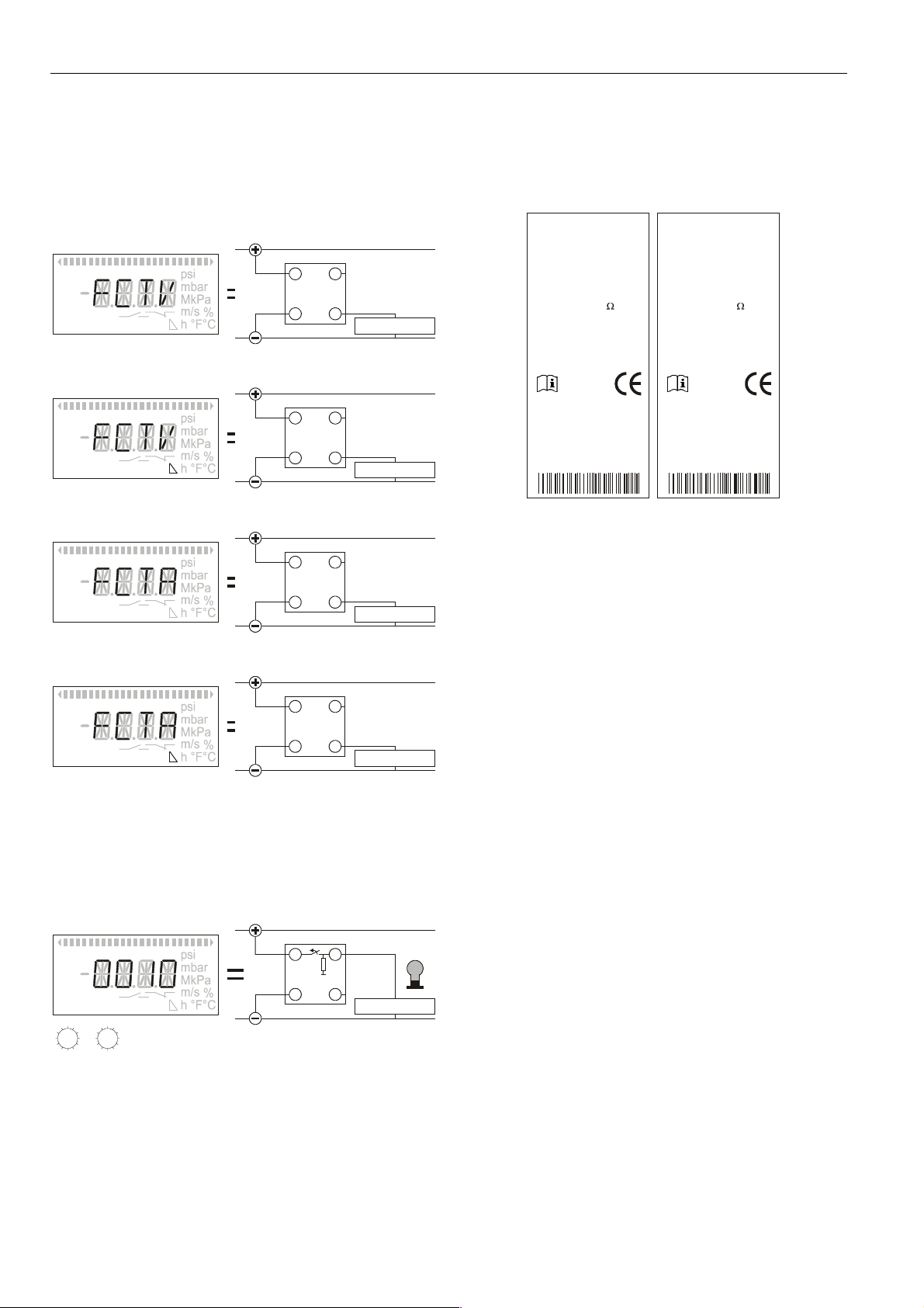
Manufacturer's Plate
The manufacturer's plate contains important technical data.
TST050G12100
-50...+50 °C
14...36 (> 50 °C: 14...30) Vdc
100mA
I of OUT1[2]: 250 mA
max
Analog Out:
0...10V max. 1mA
4...20mA max. 500
IP65 0138
F.-Nr.: 00577410005
FEMA Regelgeräte
Honeywell AG
D-71101 Schönaich
Made in Germany
www.honeywell.de\fema
TST050G12100-R
-50...+50 °C
14...36 (>50 °C: 14...30) Vdc
100mA
I of OUT1[2]: 250 mA
max
Analog Out:
0...10V max. 1mA
4...20mA max. 500
Relays:
AC1: max. 690VA
AC15: max. 230VA
IP65 0138
F.-Nr.: 00577410001
FEMA Regelgeräte
Honeywell AG
D-71101 Schönaich
Made in Germany
www.honeywell.de\fema
Fig. 21. Manufacturer's plate / TST... and TST...-R series
The manufacturer's plate identifies the device model in the
topmost line and below that the following information:
• the nominal temperature range,
• the permissible power supply,
• the max. permissible current load at OUT1[2],
• the max. permissible current load of and max.
permissible resistance at the analog output,
• the date code,
• the manufacturing number, and
• an information symbol referring the installer to these
Installation Instructions.
Hardware Features
All configuration and parameterization data is stored in the
device.
Regardless of the current operating mode (basic or expert
mode), changed parameters and configurations become
immediately effective, but are permanently stored in the
device's memory only after confirmation via SAVE.
The WARN output (pin 2) is not configurable; rather, it is
permanently wired as a high-side switch. See Fig. 20.
EXPERT EDIT ATT
WAR N
OUT2
OUT1 SPRP
AOUT ZERO FSO INV
plug 2
1 2
10 k
τ
internal
3
4
WARN
load
(max. 20 mA, 14...36 Vdc)
12
Fig. 20. WARN output (permanent high-side)
When the device recognizes an error (see section "Error
Codes" on page 8), the WARN output will become active and
is switched (via a pull-down resistor) to 0 V (logical "low). If
MU1B-0248GE51 R0903 6
In the event of a power loss, only permanently stored values
will be again available once power has been restored.
Unstored parameters and configurations are lost! In the event
of a power loss during the transfer of data into device's
memory (via SAVE), data may be lost.
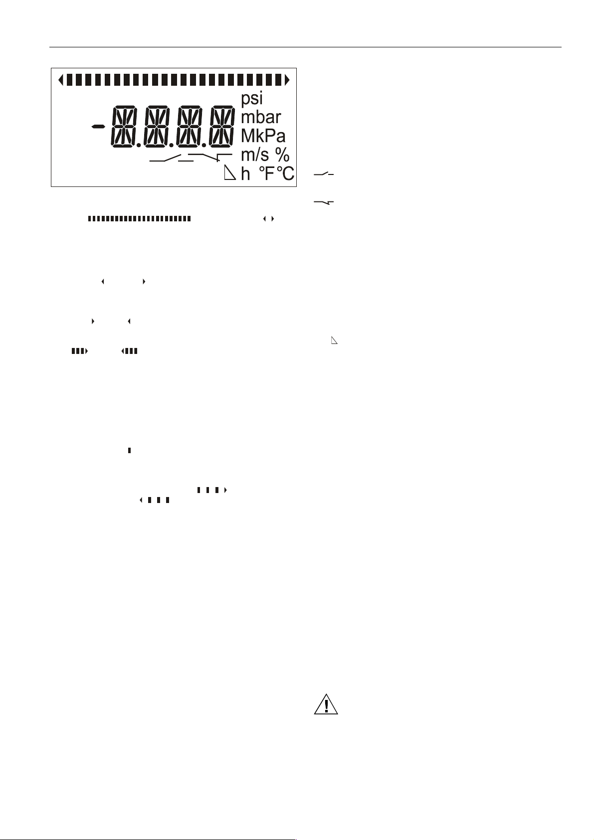
LCD Display Screen
The LCD display screen (see Fig. 22) features a four-digit
display, three decimal points, and a minus sign.
NOTE: When cleaning the display screen, use no harsh
cleaning agents.
In addition to the four-digit numeric display, the LCD display
screen can also present numerous additional symbols useful
in operating the device:
Page 7
TST... AND TST...-R ELECTRONIC TEMPERATURE SWITCHES/TRANSMITTERS
EXPERT EDIT ATT
WARN
WIN
OUT2
OUT1 SPRP
AOUT ZERO FSO INV
Fig. 22. LCD display screen
Bargraph (
The bar graph (at the top of the screen) consists of several
individual segments. The trend display (to the left and right of
the bar graph) consists of two arrowheads.
• When the device is displaying the current temperature,
the left (
to indicate dropping or rising temperature.
• While an output is being parameterized (in the basic
mode) to act as a max. or min. temperature monitor, the
right (
• When an output is being configured (in the expert mode)
to act as a max. or min. temperature monitor, the right
(
three segments of the bar graph will appear.
• When the device is displaying the current temperature,
the number of segments of the bar graph proportional to
the current temperature will appear. Thus, if the current
temperature is equal to the min. measurable temperature, no segments will be displayed; if the current
temperature is equal to the device's max. measurable
temperature, all of the segments will be displayed.
• When parameterizing the device, a single segment of
the bar graph (
to the set value.
• When viewing the max./min temperature or the time
elapsed since the max./min temperature were registered,
the max. drag indicator symbol (
indicator symbol (
EDIT
After the EDIT symbol has been made to appear (see
sections "Setting Parameters in the Basic Mode" on page 12
and "Configuring in the Expert Mode" on page 15), values (in
the basic mode) or units (in the expert mode) can be
changed by rotating and pressing the RPB (rotary/push
button).
Units
You may choose from among the following temperature units:
• °C
• °F.
Settings
These symbols appear during parameterization /
configuration.
ATT Switch-ON/OFF delay (in seconds)
EXPERT Expert mode (enabling the user to change
WARN Warning / alarm
) or right ( ) arrowhead (respectively) will appear
) or left ( ) arrowhead (respectively) will appear.
) or left ( ) arrowhead (respectively) together with
) will appear at a position corresponding
measurement units, switch-points, etc.)
) and Trend Display ( )
) or min. drag
), respectively, is displayed.
WIN Window monitor (for monitoring a temperature
OUT1 Output 1
OUT2 Output 2
SP Switch-point or, in the case of monitoring a
RP Reverse switch-point or, in the case of monitoring
AOUT Analog output (if the current temperature is
ZERO Zero-point of the analog output. Also, it appears if
FSO Full-Scale Output, i.e. upper limit of the analog
INV
See also sections "Sequence of Display Screens in Basic
Mode" on page 10 and "Overview of Parameterization and
Configuration" on page 20, where you will find an explanation
of when the various different screens will appear and for
additional information on the meanings of the individual
symbols.
range)
temperature window (WIN), the upper or lower
temperature limit
a temperature window (WIN), the upper or lower
temperature limit
OUT1[2] configured to be an N.O. switch (FSO or
ZERO also displayed) or as push-pull switch (FSO
and ZERO also displayed)
OUT1[2] configured to be an N.C. switch (FSO or
ZERO also displayed) or as inverted push-pull
switch (FSO and ZERO also displayed)
outside of the span, the AOUT symbol will not be
visible on the screen)
OUT1[2] has been configured to be a low-side
switch (i.e. the device switches logical "low" to the
output)
output. Also, it appears if OUT1[2] has been configured to be a high-side switch (i.e. the device
switches logical "high" to the output)
Inversion of the analog signal (i.e. output is then
configured as 10...0 V or 20...4 mA instead of as
0...10 V or 4...20 mA, respectively)
Time-Out Function
The time-out represents a 1-minute period during which the
device will remain in the basic mode or expert mode (as the
case may be) without automatically reverting to the display
state (whereupon already-changed but not-yet-saved values
will be lost). During the time-out, any manipulation of the RPB
will restart the internal clock, thus prolonging the time-out for
an additional 1 minute and allowing the user to continue
parameterization and/or configuration.
IMPORTANT
If the user allows (by not manipulating the RPB for 1
minute) the time-out to completely elapse, the device will
automatically revert to the display state (i.e. show the
current temperature), and already-changed but not-yetsaved values will be lost.
However, when the device is in the expert mode, the
time-out is enabled only as long as no configuration has
been changed. I.e. changing a configuration disables the
time-out function.
Recognition of Implausible Settings
CAUTION
The software automatically recognizes implausible settings of
SP, RP, ZERO, and FSO. The last-set value takes
MU1B-0248GE51 R09037
Page 8
TST... AND TST...-R ELECTRONIC TEMPERATURE SWITCHES/TRANSMITTERS
precedence over the first-set value. Thus, upon permanently
storing the last-set value, the first-set value will be shifted
right up to the second-set value, as necessary.
In the case of an implausible setting, the corresponding LED
(for OUT1 or OUT2, as the case may be) will light up red.
When this setting is then stored, the value of the other output
(OUT 2 or OUT1, as the case may be) will be automatically
shifted. If your parameterizations are plausible, the red LED
is extinguished and the current switching status is displayed.
Plausible parameterizations are explained below.
Parameterizing the Device to Act as a Switch
When configuring an output as a max. temperature monitor,
SP must be greater than RP; further, a predefined min.
difference between SP and RP must be observed. If this condition is not observed, the corresponding LED will turn red,
and upon permanently storing the settings, the other value
(SP or RP, respectively) will be shifted; SP will then be equal
to RP. The LED will remain red until the min. difference is set.
When configuring an output as a min. temperature monitor,
SP must be less than RP; further, a predefined min.
difference between SP and RP must be observed. If this condition is not observed, the corresponding LED will turn red,
and upon permanently storing the settings, the other value
(SP or RP, respectively) will be shifted; SP will then be equal
to RP. The LED will remain red until the min. difference is set.
CAUTION
After setting the switch-point or reverse switch-point of an
output to act as a min. or max. temperature monitor and after
storing this configuration, you must check if the corresponding switch-points indeed have the desired values and
that the red LED has been extinguished.
NOTE: When configuring an output to act as a window
monitor (WIN), the only restriction applying to the
relative values of SP and RP is that the min.
difference be observed. SP can be greater or less
than RP.
Parameterizing the Analog Output
When configuring the analog output in order to define a span
(i.e. that portion of the device's total measuring range which
is of particular interest to you), FSO minus ZERO must be
greater than or equal to 30% of the device's total measuring
range. If this is not the case, no error is displayed; rather, the
first-set value (i.e. FSO or ZERO, as the case may be) will be
automatically shifted, as necessary.
or 10 V, as the case may be; when configured as FCTA, it is
limited to 4 mA or 20 mA, as the case may be.
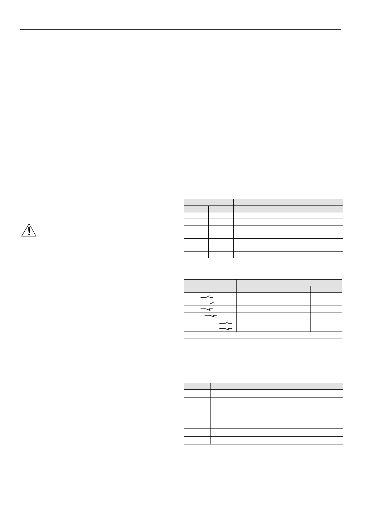
Indicator LEDs
The condition (status) of the switch outputs is indicated by
means of two LEDs located below the display screen. These
two LEDs can display three different colors having the
following meanings:
• Orange: The corresponding output is active.
• Green: The corresponding output is not active (if
specified as a WARN output, "green" likewise means
that the WARN output is not active)
• When editing (EDIT) SP/RP, only the LED of that output
being edited is illuminated; in the event of implausible
values for RP and/or SP, the corresponding LED will
light up red.
• If both indicator lights are illuminated red and the
"WARN" symbol appears: WARN mode.
• If both indicator lights are illuminated, but the "WARN"
symbol does not appear: Implausible RP/SP for both
outputs.
Table 2. Meaning of LED indicators
LED status meaning
LED 1 LED 2 OUT1 status OUT2 status
orange orange active active
green green inactive inactive
orange green active inactive
green orange inactive active
red red error (WARN) or 2x implausible
red -- implausible --
-- red -- implausible
Table 3. Potential of outputs in dependence upon their
symbols in
display
FSO, N.O. high-side "high" floating
ZERO, N.O. low-side "low" floating
FSO, N.C. high-side floating "high"
ZERO, N.C. low-side floating "low"
ZERO, FSO, push-pull "high" "low"
ZERO, FSO, inv. push-pull "low" "high"
N.O. = normally-open; N.C. = normally closed
configuration and status
configuration
active inactive
output signal
Error Codes
A number of different error codes can appear in the display,
serving to indicate a variety of faulty states.
NOTE: The specified accuracy refers to the respective
temperature range. E.g. at FSO minus ZERO =
50%, the accuracy then amounts to 1% of the
correspondingly narrower range.
NOTE: After shifting the value of ZERO, the value of FSO
must be checked and vice-versa.
If the current measured temperature is outside of the
selected span (i.e. either below ZERO or above FSO), the
AOUT symbol will not be visible on the screen and the
current temperature will be displayed. When configured (in
the expert mode) as FCTV, the analog signal is limited to 0 V
MU1B-0248GE51 R0903 8
Table 4. Error codes
text meaning
***1 sensor failure
**1* power supply voltage too low
*1** excessively low ambient temperature
*2** excessively high ambient temperature
1*** OUT1 is overloaded
2*** OUT2 is overloaded
3*** OUT1 and OUT2 both overloaded
Page 9

TST... AND TST...-R ELECTRONIC TEMPERATURE SWITCHES/TRANSMITTERS
Rotary/Push Button (RPB)
Pushing the RPB: Pushing the RPB (rotary/push button)
confirms (in certain cases: rejects) the selections you have
made.
Rotating the Rotary/Push Button: When the EDIT symbol
has been called up, rotating the RPB (CW or CCW)
individual ticks increases or decreases (as the case may be)
the given displayed value. Otherwise, rotating the RPB
sweeps through a sequence of screens.
Possible Settings
Switching Delay ("ATT" Symbol)
The user can employ a convenient function to mask shortterm temperature fluctuations and peaks: the switching delay.
The switching delay can be set to values in the range of
1...3600 seconds. Any subsequent variation in temperature
which does not have the set minimum duration will still be
shown in the display and will be registered by the drag
indicator, but will nonetheless be unable to trigger a switch.
This delay can be applied to the switch-on behavior (
the switch-off behavior, (
), or to both ( ).
),
Locking/Unlocking the Device
Defining a Non-Zero Code
NOTE: The following explanations assume that the device
In order to prevent the unauthorized changing of parameters
and configurations, the user can define a 4-digit, non-zero
code (without a minus sign, and having a value of between
0001 and 9999). This is done by going through the expert
mode's sequence of screens until reaching the screen
shown in Fig. 54.
• The text "CODE" then means that a code has not yet
• The text "LOCK" then means that a code has already
Assuming that the text "CODE" has appeared, you must now
press the RPB in order to confirm that you do indeed wish to
define a code. "0000" will then appear in the display.
The desired code must now be defined by sequentially
rotating (to select) and pressing (to confirm) the RPB for
each digit of the desired code (which must be a 4-digit
number between 0001 and 9999). After the fourth digit of the
desired code has been defined, the text "LOCK" will appear.
You should then rotate the RPB CW one tick, whereupon the
"EXIT" screen (Fig. 55) will appear. After confirming this by
pressing the RPB, the device will re-enter the basic mode,
and the 1-minute grace period will immediately become
effective (see also section "Time-Out Function" on page 7).
If a non-zero code has been defined, the following will apply:
• If the 1-minute grace period is allowed to elapse, or
• if the device is turned OFF and then ON again,
is still in the default shipping setting (i.e. "EXPN" =
not locked for configuration). Otherwise, see
section "Locking the Device for Configuration
("EXPN" -> "EXPL")" on page 9.
been defined and that the user is free to define one.
been defined and, moreover, that the device has already
been locked.
the device will immediately become locked for parameterization and configuration. It is then no longer possible
to make changes to parameters or configurations without first
unlocking the device; rather, parameters can then be viewed,
only. Thus, a parameter can be selected (and will also be
displayed), but after pressing the RPB, instead of the value
changing, the text "LOCK" will appear in the screen for 1
second, after which the unchanged value will re-appear.
In order to be able to again change parameters, it is
necessary to unlock the device (also section "Unlocking a
Locked Device" below).
Unlocking a Locked Device
A device locked for parameterization and configuration can
be unlocked by inputting the correct code. This is done by
going through the basic mode's sequence of screens (Fig. 26
to Fig. 37) and stopping at the last screen, in which the text
"CODE" (instead of "EXP") will appear, thus prompting the
user to input the correct code. You must now press the RPB
in order to confirm that you wish to input the code. "-- -- -- --"
will appear in the display.
The correct code must now be inputted by sequentially
rotating (as appropriate) and pressing the RPB for each digit
of the code (which must be a 4-digit number between 0001
and 9999).
If you have inputted the incorrect code, the device will remain
in the basic mode and display the text "CODE".
Inputting the correct code will place the device into the expert
mode. The 1-minute grace period will then immediately
become effective again. The user then has the option of
either remaining in the expert mode (where configurations
can be viewed and changed) or of entering the basic mode.
Defining No Code (CODE = 0000)
Defining (and permanently storing) a code of 0000 (which is
the default shipping setting) means that that the device will
under no circumstances ever become locked. If, while in the
expert mode, any parameters / configurations are then
changed but not permanently stored (via SAVE), the device
will nevertheless remain in the expert mode until either a
SAVE or a REST (for "restore") is performed.
Locking the Device for Configuration ("EXPN" -> "EXPL")
It is possible to lock the device for configuration; thereafter, it
is still possible to enter the expert mode, but it is impossible
to make any changes while there. To do this, it is necessary
to change the default shipping setting of "EXPN" to "EXPL".
This can be done during the power-up sequence as follows:
1. Immediately after the power is turned ON, press and
hold down (for approx. 5 seconds) the RPB until the
software version is displayed.
2. Now rotate the RPB CW and go through the sequence of
screens until you reach a screen displaying either "EXP"
(indicating that as yet no code [CODE = 0000] had been
defined) or "CODE" (indicating that a non-zero code has
already been defined). If "EXP" appears, you can enter
the expert mode and press the RPB to proceed
immediately to step 3. If "CODE" appears, you must first
input the correct code in order to enter the expert mode,
press the RPB, and then proceed to the step 3.
MU1B-0248GE51 R09039
Page 10

TST... AND TST...-R ELECTRONIC TEMPERATURE SWITCHES/TRANSMITTERS
3. Rotate the RPB CW until you come to a screen
displaying either "CODE" (indicating that as yet no code
[CODE = 0000] had been defined) or "LOCK" (indicating
that a non-zero code has already been defined).
Regardless, you must now press the RPB. You can now
either input the same (old) code or define a new code.
4. The very next screen to appear will display either
"EXPN" or "EXPL" (see Table 5 for the code-dependent
meaning of this text; the first line is the default shipping
setting). Changing "EXPN" to "EXPL" locks the device
for configuration. Changing "EXPL" to "EXPN" unlocks
the device for configuration.
Table 5. Code-dependent meaning of text at power-up
code text
0000 EXPN unlocked unlocked
0000 EXPL unlocked locked
≠0000 EXPN locked unlocked
≠0000 EXPL locked locked
Lost/Forgotten Code
In the event that you have lost or forgotten your code, you
can also unlock the device by means of the master code
obtained from Honeywell (when contacting Honeywell, please
state your device's serial number).
parameterization
(basic mode)
configuration
(expert mode)
Operating Sequence
If the user does not manipulate the RPB for 30 seconds, and
if "LED-" has been set (in the expert mode), the LCD display
screen's backlighting will be shut off automatically (see Fig.
25). If (in the expert mode) "LED+" has been set, the LCD
display screen's backlighting will remain on permanently.
Sequence of Display Screens in Basic Mode
When in the basic mode, rotating the RPB one tick CW at a
time results in the presentation, in the following sequence
(see Fig. 26 to Fig. 37), of all of the individual screens
available in this mode. At any time, you may rotate the RPB
CCW to go back to earlier screens in the reverse sequence.
Fig. 24. LCD display screen after power-up
Fig. 25. LCD display screen 30 s after last manipulation
Power Up
After power has been supplied, the backlighting is activated,
thus illuminating the LCD display, and all of the symbols
appear. Further, the two LEDs are illuminated for one second
(see Fig. 23).
EXPERT EDIT ATT
WARN
WIN
OUT2
OUT1 SPRP
AOUT ZERO FSO INV
Fig. 23. LCD display screen and LEDs on power-up
Basic Mode
After one second, the display goes into the so-called basic
mode. The basic mode is used to display and change (i.e. to
parameterize) SP/RP, ZERO, and FSO, to set the switching
delay, to view/reset the drag (min./max.) temperature
indicators, and to enter the expert mode.
In the first screen (see example in Fig. 24), the current
temperature (as a digital value and bar graph), the corresponding temperature unit, and the trend (increasing /
decreasing temperature) are displayed.
Display state: If the user does not manipulate the RPB for
60 seconds, regardless of the current screen, the LCD
display screen will revert to the first screen displaying the
temperature.
The values displayed in the following examples are valid for
devices of the PST...-R series, which was chosen because it
embodies the full range of possible functions. In the case of
devices of the PST... series, symbols referring to the relay
output will be displayed, but the text "NAPL" ("not
applicable") will appear in the text display.
Fig. 26. First screen displayed in the basic mode
After rotating the RPB one tick CW, the next screen, with
information about the switch-point (SP) of output 1, will be
displayed (see example in Fig. 27; in this case, OUT1 has
been configured as an N.O. high-side switch and as a max.
temperature monitor with a switch-point of 30 °C).
MU1B-0248GE51 R0903 10
Page 11

TST... AND TST...-R ELECTRONIC TEMPERATURE SWITCHES/TRANSMITTERS
A
A
has been configured as an N.O. low-side switch for window
monitoring, with a reverse switch-point of 32 °C).
OUT1 SP
FSO
Fig. 27. Next screen after rotating the RPB
After rotating the RPB another tick CW, the next screen, with
information about the reverse switch-point (RP) of output 1,
will be displayed (see example in Fig. 28; in this case, OUT1
has been configured as an N.O. high-side switch and as a
max. temperature monitor with a reverse switch-point of 20
°C).
OUT1 RP
FSO
Fig. 28. Next screen after rotating the RPB
After rotating the RPB another tick CW, the next screen, with
information on the switching delay for OUT1, will be
displayed (see example in Fig. 29; in this case, the switching
delay has been switched OFF).
WIN
OUT2
RP
ZERO
Fig. 31. Next screen after rotating the RPB
After rotating the RPB another tick CW, the next screen, with
information about the switching delay for OUT2, will be
displayed (see example in Fig. 32; in this case, a switching
delay of 520 seconds has been configured).
TT
OUT2
Fig. 32. Next screen after rotating the RPB
After rotating the RPB another tick CW, the next screen, with
information about the zero-point (ZERO) of the analog output,
will be displayed (see example in Fig. 33; in this case, the
analog output has been configured with a ZERO of -10 °C).
TT
OUT1
Fig. 29. Next screen after rotating the RPB
After rotating the RPB another tick CW, the next screen, with
information about the switch-point (SP) of output 2, will be
displayed (see example in Fig. 30; in this case, OUT2 has
been configured as an N.O. low-side switch for window
monitoring, with a switch-point of 35 °C).
WIN
OUT2
SP
ZERO
Fig. 30. Next screen after rotating the RPB
After rotating the RPB another tick CW, the next screen, with
information about the reverse switch-point (RP) of output 2,
will be displayed (see example in Fig. 31; in this case, OUT2
AOUT ZERO
Fig. 33. Next screen after rotating the RPB
After rotating the RPB another tick CW, the next screen, with
information about the upper limit (FSO) of the analog output's
measuring range, will be displayed (see example in Fig. 34;
in this case, the analog output has been configured with an
FSO of +140 °C).
AOUT FSO
Fig. 34. Next screen after rotating the RPB
After rotating the RPB another tick CW, the next screen, with
information about the min. temperature (recorded by the drag
indicator) will be displayed (see example in Fig. 35; in this
case, the lowest temperature recorded was 15 °C).
MU1B-0248GE51 R090311
Page 12

TST... AND TST...-R ELECTRONIC TEMPERATURE SWITCHES/TRANSMITTERS
Setting Parameters in the Basic Mode
If the device has been locked for parameterization, you will
be unable to do more than view values.
After having unlocked the device (see section "Unlocking a
Fig. 35. Next screen after rotating the RPB
If you now press the RPB, the EDIT symbol will appear,
whereupon you can make the drag indicator's timer appear
by rotating the RPB one tick CW. The timer displays how
long ago (in hours) the min. temperature occurred (e.g. "1.38
h" means that it occurred 1 hour and 38 minutes ago).
Rotating the RPB another tick CW and then pressing it will
reset the timer.
Locked Device"), however, you will be able to change values.
To change a particular value (after unlocking), the display
screen must first be made to present the desired parameter
by going through the sequence of screens listed above until
the corresponding screen is reached (see example in Fig.
38).
NOTE: Immediately after power-on, and until the timer has
been reset, the timer function is not available (and
the text "NAVL" will appear in the display).
After rotating the RPB another tick CW, the next screen, with
information about the max. temperature (recorded by the
drag indicator) will be displayed (see example in Fig. 36; in
this case, the highest temperature recorded was 28 °C).
Fig. 36. Next screen after rotating the RPB
If you now press the RPB, the EDIT symbol will appear,
whereupon you can make the drag indicator's timer appear
by rotating the RPB one tick CW. The timer displays how
long ago (in hours) the max. temperature occurred (e.g. "0.44
h" means that it occurred 44 minutes ago). Rotating the RPB
another tick CW and then pressing it will reset the timer.
NOTE: Immediately after power-on, and until the timer has
been reset, the timer function is not available (and
the text "NAVL" will appear in the display).
After rotating the RPB another tick CW, the next and final
screen will be displayed (see Fig. 37).
OUT1 SP
FSO
Fig. 38. Displaying the desired parameter to be edited
Press the RPB. The screen remains unchanged except that
the EDIT symbol appears (see Fig. 39).
OUT1 SP
FSO
Fig. 39. Display screen after appearance of EDIT symbol
If the RPB is now rotated CW or CCW, the value will correspondingly rise or drop in increments / decrements which
depend upon the model (see example in Fig. 40).
Fig. 37. Final screen after rotating the RPB
The final screen will display either "EXP" or " CODE" (see
section "Unlocking a Locked Device" on how to input the
code).
Upon reaching this final screen, you can return to any one of
the previous screens by rotating the RPB individual ticks
CCW. The previous screens will then be again displayed,
though in the reverse order.
MU1B-0248GE51 R0903 12
OUT1 SP
FSO
Fig. 40. Display screen after increasing value of desired
parameter
After the desired value has been reached, again pressing the
RPB will cause the following screen to appear (see Fig. 41).
However, if no values have been changed, it is not necessary
to save.
Page 13

EDIT
TST... AND TST...-R ELECTRONIC TEMPERATURE SWITCHES/TRANSMITTERS
OUT1 SP
FSO
Fig. 41. Display screen after pressing the RPB: SAVE
You now have only two choices: You can either accept or
reject the new value.
• Accept: Pushing the RPB now means that you want to
permanently save the new value.
• Reject: Rotating the rotary/press button one tick CCW
will cause the next screen to appear (see Fig. 42).
EDIT
OUT1 SP
FSO
Fig. 42. Next screen after rotating back the RPB
If you now press the RPB, the new values will be rejected,
and the former values will be reinstated in the permanent
memory.
Fig. 43. First screen displayed in the expert mode
After rotating the RPB one tick CW, the next screen, with
information about the function of output 1, will be displayed
(see Fig. 44; in this case, OUT1 has been configured as an
N.O. low-side switch).
Fig. 44. Function display for OUT1 in expert mode
After rotating the RPB another tick CW, the next screen, with
information about the configuration of output 2, will be
displayed (see Fig. 45; in this case, OUT2 has been configured as a temperature window monitor).
NOTE: In contrast to the other functions which can be
parameterized in the basic mode, when adjusting
the switching delay, after pressing the RPB, it is
necessary to make a further specification, namely
whether the switching delay should apply to the
switch-on behavior (
), or to both ( ).
(
), the switch-off behavior
Sequence of Screens in Expert Mode
When in the expert mode, rotating the RPB individual ticks
results in the presentation in a sequence of all of the
individual screens of this mode. At any time, the sequence
can be halted by pressing the RPB, whereupon parameters
can be redefined/reconfigured by rotating the RPB. The
values displayed in the following figures are examples.
In the first screen, the configuration of output 1 is displayed
(see example in Fig. 43; in this case, OUT1 has been configured as a max. temperature monitor).
Fig. 45. Next screen after rotating the RPB
After rotating the RPB another tick CW, the next screen, with
information about the function of output 2, will be displayed
(see Fig. 48; in this case, OUT2 has been configured as an
N.C. high-side switch).
Fig. 46. Function display for OUT2 in expert mode
After rotating the RPB another tick CW, the next screen, with
information about the function of the analog voltage output
MU1B-0248GE51 R090313
Page 14

TST... AND TST...-R ELECTRONIC TEMPERATURE SWITCHES/TRANSMITTERS
(FCTV) or analog current output (FCTA), will be displayed
(see Fig. 47).
Fig. 47. Next screen after rotating the RPB
The "V" means that the analog output is configured for
0...10 V. By causing the INV
symbol to appear, this can be
changed to 10...0 V.
The "A" means that the analog output is configured for
4...20 mA. By causing the INV
symbol to appear, this can
be changed to 20...4 mA.
After rotating the RPB another tick CW, the next screen, with
information about the switch-over contact relay, will be
displayed (see example in Fig. 48; in this case, the relay has
been coupled with OUT1).
Fig. 48. Next screen after rotating the RPB
After rotating the RPB another tick CW, the next screen, with
information about the unit of temperature, will be displayed
(see Fig. 49). In this example, the device has been
configured for °C.
To balance the device, proceed as follows:
1. Immediately after turning ON the power (i.e. during the
power-up sequence), press and hold down (for approx. 5
seconds) the RPB until the software version is displayed.
Enter the expert mode and select SET0.
2. Rotate the RPB until the actual temperature is displayed.
If you wish to return the device to its original factory settings,
you must rotate the RPB until the left (
) and right ( ) trend
arrow heads appear simultaneously.
After rotating the RPB another tick CW, the next screen, with
information about the given sensor connection (two-wire or
three-wire, as the case may be) will be displayed (see also
section "Connecting the Sensor" on page 4). In this case,
(see example in Fig. 51), a three-wire sensor has been connected (this is the default setting). To change this configuration, see section "Reconfiguring the Sensor Connection" below.
EXPERT
Fig. 51. Next screen after rotating the RPB
Reconfiguring the Sensor Connection
The reconfiguration of the device to correspond to the given
sensor connection is a hidden function, and can be carried
out only immediately after switching ON the device and while
in the expert mode.
To reconfigure the device, you must turn OFF. Immediately
after turning the device back ON, press and hold down the
RPB for approx. 5 seconds, after which the software version
will appear in the display. You must then enter the expert
mode and choose "WIR2" or "WIR3", as appropriate.
Fig. 49. Next screen after rotating the RPB
After rotating the RPB another tick CW, the next screen will
be displayed (see example in Fig. 50).
EXPERT
Fig. 50. Next screen after rotating the RPB
After pressing the RPB, the current measured temperature
will be displayed. If this temperature deviates from the actual
temperature, you should balance the device. See section
"Balancing the Device" below).
Balancing the Device
Balancing is a hidden function which can be carried out only
immediately after switching the device on and while in the
expert mode.
After rotating the RPB another tick CW, the next screen, with
information about adjusting the display backlighting, will be
displayed (see Fig. 53). In this example, the LED has been
set to remain ON permanently (+).
EXPERT
Fig. 52. Next screen after rotating the RPB
After rotating the RPB another tick CW, the next screen, with
information about simulation modes, will be displayed (see
Fig. 53). In this example, the simulation mode has been
turned OFF.
EXPERT
Fig. 53. Next screen after rotating the RPB
MU1B-0248GE51 R0903 14
Page 15

TST... AND TST...-R ELECTRONIC TEMPERATURE SWITCHES/TRANSMITTERS
See also section "Configuring and Executing a Simulation"
on page 17 for an explanation of how to configure and
execute simulation modes.
After rotating the RPB another tick CW, the next screen, with
information about the code or lock, will be displayed (see Fig.
54). If no code has been set (i.e. code = 0000), the left
display will appear; if a code has been set (i.e. code = 0001
to 9999), the right display will appear.
Fig. 54. Next screen after rotating the RPB
After rotating the RPB another tick CW, the final screen of
the expert mode will be displayed (see Fig. 55).
Fig. 57. Display screen after appearance of EDIT symbol
If the user now again presses the RPB, the screen will revert
to its appearance in Fig. 56. If, however, the RPB is rotated
CW or CCW, different configuration options (in this example:
°F instead of °C) will appear accordingly.
Fig. 58. Display screen after selecting a different unit
If the user now again presses the RPB, the screen will revert
to its appearance in Fig. 56, though with a new unit (namely:
°F). If, however, the RPB is instead rotated to the end of the
sequence, the "EXIT" screen will appear (see Fig. 59).
Fig. 55. Final screen after rotating the RPB
You can return to any of the previous screens by rotating the
RPB individual ticks CCW. The previous screens will be
again displayed, though in the reverse order.
NOTE: If, while in the expert mode, no configuration is
changed, following the time-out (one minute), the
device will revert to the basic mode.
NOTE: If, while in the expert mode, a value is changed,
the device will remain at that position of the
sequence of screens until the user defines a value
via either "SAVE" or "REST."
Configuring in the Expert Mode
The screen must be made to present the desired parameter
by going through the sequence of screens listed above until
the corresponding screen is reached (see example in Fig.
56).
Fig. 56. Displaying the desired parameter to be edited
Fig. 59. Display screen after rotating the RPB to the end
of the display sequence
You can now press the RPB to confirm that you want to exit
the editing sequence, and then rotate the RPB CW or CCW
(as the case may be) until either "SAVE" (see Fig. 60) or
"REST" (see Fig. 61) appears in the screen.
Fig. 60. Display screen after rotating the RPB to "SAVE"
You now have only two choices: You can either accept or
reject the new parameters. Pushing the RPB now means that
you want to permanently save the new parameters. Rotating
the rotary/press button one tick CW will cause the next
screen to appear (see Fig. 61).
Press the RPB. The screen remains unchanged except that
the EDIT symbol now appears (see example in Fig. 57).
Fig. 61. Display screen after rotating the RPB to "REST"
If the user now presses the RPB, the new values will be
rejected, and the former values will be reinstated in the
MU1B-0248GE51 R090315
Page 16

TST... AND TST...-R ELECTRONIC TEMPERATURE SWITCHES/TRANSMITTERS
e
t
e
t
e
t
permanent memory. Following either the "REST" or "SAVE"
screen, the device will revert to the basic mode.
Example Configurations in the Expert Mode
NOTE: When configuring an output as a max. or min.
temperature monitor or window monitor (WIN), it
may occur that the LED of the corresponding
output will light up red. This indicates that the
software has assigned SP and RP implausible
values (e.g. SP = RP). In this case, you will have
to enter the basic mode and change the values of
SP and/or RP so that the red LED is extinguished.
Furthermore, the red LED also lights up when the
current temperature is displayed in the basic mode
or when the settings are implausible.
Configuration of an Output as a Max. Temperature Monitor
When one of its output has been configured as a max. temperature monitor, the device serves to monitor and act upon
changes of temperature relative to a pre-selected upper limit
(SP). The corresponding output will then switch as soon as
this upper limit is exceeded. On the basis of this switching
process, a controller could then e.g. reduce the temperature.
As soon as the temperature drops below the reverse switchpoint (RP), the output will revert to its initial state. Thus, the
switching process is triggered when the temperature rises
above SP, while the reverse switching process is triggered
when the temperature drops below RP!
increase the temperature. As soon as the temperature rises
above the reverse switch-point (RP), the device will revert to
its initial state. Thus, the switching process is triggered when
the temperature drops below SP, while the reverse switching
process is triggered when the temperature rises above RP!
emperature
RP
e.g. +5 °C
SP
e.g. +20 °C
= active
= inactive
tim
Fig. 64. Min. temperature monitor
Example:
EXPERT
SPRP
emperature
SP
e.g. +35 °C
RP
e.g. +28 °C
= active
= inactive
tim
Fig. 62. Max. temperature monitor
Example:
EXPERT
SPRP
Fig. 63. OUT1 configured as a max. temperature monitor
Configuration of an Output as a Min. Temperature Monitor
When one of its output has been configured as a min. temperature monitor, the device serves to monitor and act upon
changes of temperature relative to a pre-selected lower limit
(SP). The corresponding output will then switch as soon as
the temperature drops below the set min. value. On the basis
of this switching process, a controller could then e.g.
Fig. 65. OUT1 configured as a min. temperature monitor
Configuration of an Output as a Window Monitor
When one of its outputs has been configured as a window
monitor, the device serves to monitor and act upon changes
of temperature beyond a pre-selected range. The corresponding output will then switch as soon as the temperature leaves the set range. On the basis of this switching
process, a controller could then e.g. increase or decrease the
temperature, as appropriate. As soon as the temperature
returns to the pre-selected range, the device will revert to its
initial state. Thus, the switching process is triggered when the
temperature leaves the pre-selected range, though with a
certain degree of hysteresis (in order to prevent uncontrolled
switching on the part of the temperature controller).
emperature
RP or SP
e.g. +40 °C
SP or RP
e.g. +30 °C
= active
= inactive
internal
hysteresis
internal
hysteresis
tim
Fig. 66. WIN temperature monitor
MU1B-0248GE51 R0903 16
Page 17

TST... AND TST...-R ELECTRONIC TEMPERATURE SWITCHES/TRANSMITTERS
Fig. 67. OUT1 configured as a "WIN" monitor
display screen will display information and the two LED's
will light up / change color / go out just as though the
temperature were actually changing. As long as the
simulation is running, the text "SIM1" will be displayed
every ten seconds for five seconds. After a while
(approx. 30 minutes), the simulation mode is deactivated
automatically.
NOTE: When configuring an output as a window monitor
(WIN), the only restriction applying to the relative
values of SP and RP is that the min. difference be
observed. SP can be greater or less than RP.
Configuring and Executing a Simulation
There are two simulation modes: SIM1 and SIM2.
The purpose of SIM1 is to allow the user to test his configurations by rotating the RPB (which simulates increasing /
decreasing temperature) and simultaneously observing if the
LED's are lit at the appropriate temperature values and if the
corresponding information (text, symbols) appears in the
display.
The purpose of SIM2 is to allow the user to check the
flawless functioning of downstream devices connected to the
SmartTemp by switching the SmartTemp's outputs ON and
OFF in periodic intervals. Specifically, the user can set the
switch periods of the two outputs (OUT 1 and OUT2) in a
range of from 300 ms to 20 sec (corresponding to a set value
of from 0.0 to 100.0%; see
Table 6. Set value and corresponding switch period
set value switch period
0% approx. 300 ms
1% approx. 500 ms
5% approx. 1 s
10% approx. 2.5 s
50% approx. 10 s
100% approx. 20 s
To set up a simulation mode, proceed as follows:
1. Enter the expert mode.
2. Rotate the RPB CW until "SIM-" appears.
3. Press the RPB. The EDIT symbol will appear.
4. Rotate the RPB CW until SIM1 or SIM2 (as desired)
appears.
5. Press the RPB; the EDIT symbol will disappear.
6. Rotate the RPB CW until the text "EXIT" appears. Press
the RPB to confirm that you wish to exit the expert mode.
It is not necessary to save the simulation mode which
you have just set up – this is done automatically. However, after approx. 30 minutes, the simulation will be
automatically terminated and the device will return to
normal operation.
To execute SIM2, proceed as follows:
1. Immediately after completing the set-up described
above, the device is in the basic mode, and the FSO
(full-scale output) is displayed. Press the RPB; the EDIT
symbol and a value of 100.0% (meaning "max. switching
period") will appear.
2. Set the desired value of between 0.0% (min. switching
period = approx. 300 ms) and 100.0% (max. switching
period = approx. 20 s) by rotating the RPB CW and/or
CCW. OUT1, OUT2, the switch-over contact relay output, the analog output, and also the min./max.
temperature drag indicators will all react as though the
temperature were actually changing. Thus, as long as
the simulation is running, the device's display screen will
display information and the two LED's will light up /
change color / go out just as though the temperature
were actually changing. As long as the simulation is
running, the text "SIM2" will be displayed every ten
seconds for five seconds. After a while (approx. 30
minutes), the simulation mode is deactivated
automatically.
Warn Function
Besides pin 2 of plug 2, which is permanently wired as a
high-side switch serving as a warning output, it is also
possible to configure OUT2 (i.e. pin 2 of plug 1) as a warning
output.
In the event that the power supply voltage drops below a
critical level, or in the event of a sensor defect, operation
outside of the permitted temperature range, or overloading of
OUT1 and OUT2, the two LEDs will both light up red (see
also section "Error Codes" on page 8).
EXPERT
WARN
Fig. 68. OUT2 configured as a warning output
To execute SIM1, proceed as follows:
1. Immediately after completing the set-up described
above, the device is in the basic mode, and the FSO
(full-scale output) is displayed. Press the RPB; the EDIT
symbol will appear.
2. Rotate the RPB CW and/or CCW, thus simulating
increasing/decreasing temperature. OUT1, OUT2, the
switch-over contact relay output, the analog output, and
also the min./max. temperature drag indicators will all
react as though the temperature were actually changing.
Thus, as long as the simulation is running, the device's
MU1B-0248GE51 R090317
Page 18

TST... AND TST...-R ELECTRONIC TEMPERATURE SWITCHES/TRANSMITTERS
A
FACTORY SETTINGS
feature factory setting
definition max. temperature monitor
function normally-open low-side output
OUT1
OUT2
SP two-thirds of FSO
RP one-third of FSO
ATT OFF
definition temperature window monitoring
function normally-open low-side output
SP two-thirds of FSO
RP one-third of FSO
ATT OFF
function non-inverted (normal, i.e.: 0...10 V)
ZERO lower limit of measuring rangeAOUT
FSO upper limit of measuring range
REL coupled with OUT1
Unit °C
Code 0000 (= no code / unlocked), EXPN
LOST/FORGOTTEN CODE
In the event that you have lost or forgotten your code, you
can also unlock the device by means of the master code
obtained from Honeywell (when contacting Honeywell, please
state your device's serial number).
40
25
8.4
50
20
4.5
5
.
4
44
58
50
80
100
ACCESSORIES
The following accessories are not included in the shipment,
but can be ordered.
M12 Couplings
For Plugs 1+2
For plugs 1+2 (5-prong plug for power supply and switching /
analog outputs):
• ST12-5-G (straight design)
• ST12-5-A (angled design)
For Plug 3
For plug 3 (3-prong relay output of TST...R):
• ST12-4-G (straight design)
• ST12-4-A (angled design)
• ST12-4-GK (straight design with 2-meter-long cable)
• ST12-4-AK (angled design with 2-meter-long cable)
Other Accessories
• AST1 wall mounting set (for attaching the TST...E... for
evaluating external sensors), see Fig. 69
• ST8-3 (3-prong M8 plug as per DIN IEC 60947-5-2 with
screw terminals)
60
Fig. 69. AST1 wall mounting set
Thermowells
Material: Stainless steel 1.4571 / 316L
model A B C D E F screwing
G12-100 105 36 19 14 15 83 G ½" (cylindrical)
G12-250 255 36 19 14 15 233 G ½" (cylindrical)
R12-100 105 36 19 14 15 83 R ½" (conical)
R12-250 255 36 19 14 15 233 R ½" (conical)
N12-100 105 36 19 14 15 83 N ½" (conical NPT)
N12-250 255 36 19 14 15 233 N ½" (conical NPT)
C
E
SW27
B
D
inner screwing for
insertion sensor G 1/2”
8 x 0.7 mm
F
Fig. 70. Dimensions of thermowells
MU1B-0248GE51 R0903 18
Page 19

TST... AND TST...-R ELECTRONIC TEMPERATURE SWITCHES/TRANSMITTERS
LITERATURE
See also TST... and TST...-R Electronic Temperatur
Switches/Transmitter, Product Data (EN0B-0439 GE51).
Additional information and technical documentation in
electronic format are available under the following URL's:
www.honeywell.de/fema
and
www.fema.biz
MODELS AND TEMPERATURE RANGES
Table 7. Temperature ranges, connections, and models
temperature range
-50...+50 °C 100 built-on, G½" TST050G12100 TST050G12100-R
-50...+50 °C 250 built-on, G½" TST050G12250 TST050G12250-R
-50...+200 °C 100 built-on neck tube, G½" TST200G12100 TST200G12100-R
-50...+200 °C 250 built-on neck tube, G½" TST200G12250 TST200G12250-R
-50...+200 °C n.a. external, w/ cable* TST200EPT1K TST200EPT1K-R
-50...+400 °C n.a. external, w/ cable* TST400EPT1K TST400EPT1K-R
*Sensors not included in delivery.
sensor immersion
depth (mm)
sensor type, connection
switch / transmitter
model
switch / transmitter /
relay model
With the TST200EPT1K and TST400EPT1K, even customized PT1000 class-A sensors can be evaluated in the
aforementioned temperature ranges. PT1000 class-A sensors, only, may be used insofar as the required accuracy of 0.5% will
otherwise not be maintained.
External Sensors
temperature range
-50...+400 °C 100 2,5 m extern, G½" P2-TVS12-400-100 plug included
-50...+400 °C 250 2,5 m extern, G½" P2-TVS12-400-250 plug included
sensor immersion
depth (mm)
line length
sensor type,
connection
model remark
MU1B-0248GE51 R090319
Page 20

TST... AND TST...-R ELECTRONIC TEMPERATURE SWITCHES/TRANSMITTERS
OVERVIEW OF PARAMETERIZATION AND CONFIGURATION
activity / situation
Current Temperature Is Displayed
current temperature
OUT1 is active
OUT2 is active
AOUT (temp. between ZERO & FSO)
temperature is rising
temperature is dropping
warning
Parameterizing Output 1 [Output 2]
SP
RP
first limit of window (WIN)
second limit of window (WIN)
Configuring Output 1 [Output 2]
max. temperature monitor (SP>RP)
min. temperature monitor (SP<RP)
window monitor (WIN)
output 2 as WARN
N.C. low-side open-collector OUT1[2]
N.O. low-side open-collector OUT1[2]
N.C. high-side open-collector OUT1[2]
N.O. high-side open-collector OUT1[2]
output 1 [2] as "push-pull"
output 1 [2] as inverted "push-pull"
Parameterizing the Analog Output
first limit (ZERO) of range
second limit (FSO) of range
Configuring the Analog Output
0...10 V voltage-controlled output
10...0 V voltage-controlled output
4...20 mA current-control output
20...4 mA current-control output
Configuring the Relay
relay coupled with output 1
relay coupled with output 2
relay configured as alarm output
Configuring Unit
unit EXPERT, °C / °F UNIT NO YES
Parameterizing Switching Delay
delay type (ON or OFF or ON + OFF) OUT1 [2], SP/RP, ATT or or YES NO
minimum duration bar graph, OUT1[2], ATT, s digital value or OFF YES NO
Locking / Unlocking Device Using a Code
unlocked (code = 0000)
locked (code ≠ 0000) - CODE, digital value YES NO
1
The same symbols appearing in the expert mode are also visible in the basic mode, where they indicate the current configuration of the given
output. Exceptions: If an output has been configured to act as a max. / min. monitor, in the basic mode,
1
, OUT1 [OUT2], SP digital value YES NO
, OUT1 [OUT2], RP digital value YES NO
, OUT1 [OUT2], SP digital value YES NO
, OUT1 [OUT2], RP digital value YES NO
EXPERT, SP, RP,
EXPERT, SP, RP,
EXPERT, WIN OUT1 [OUT2] NO YES
EXPERT, WARN OUT2 NO YES
EXPERT,
EXPERT,
EXPERT,
EXPERT,
EXPERT,
EXPERT,
, AOUT, ZERO digital value YES NO
, AOUT, FSO digital value YES NO
EXPERT, AOUT FCTV NO YES
EXPERT, AOUT, INV
EXPERT, AOUT FCTA NO YES
EXPERT, AOUT, INV
EXPERT, OUT1 REL NO YES
EXPERT, OUT2 REL NO YES
EXPERT, WARN REL NO YES
LCD display shows parameters adjustable in
symbols digital values / text basic mode expert mode
, unit digital value - -
OUT1 - - -
OUT2 - - -
AOUT - - -
---
---
WARN digital value NO NO
OUT1 [OUT2] NO YES
OUT1 [OUT2] NO YES
, ZERO FCT1 [FCT2] NO YES
, ZERO FCT1 [FCT2] NO YES
, FSO FCT1 [FCT2] NO YES
, FSO FCT1 [FCT2] NO YES
, ZERO, FSO FCT1 [FCT2] NO YES
, ZERO, FSO FCT1 [FCT2] NO YES
FCTV NO YES
FCTA NO YES
-EXPYESNO
and appear instead of and .
MU1B-0248GE51 R0903 20
Page 21

TST... AND TST...-R ELECTRONIC TEMPERATURE SWITCHES/TRANSMITTERS
OVERVIEW OF PARAMETERIZATION AND CONFIGURATION (CONTINUATION)
activity / situation
Changing Code
device is locked
device is unlocked
Resetting the display lighting
ON continuously
turned OFF
Drag indicator
max. temperature measured , temperature unit (°C / °F)
time since max. temperature , EDIT, h
min. temperature measured , temperature unit (°C / °F)
time since min. temperature , EDIT, h
storage reset [ ], EDIT
Simulation modes
configuring a simulation mode EXPERT, EDIT SIM- / SIM1 / SIM2 NO YES
execute temp. simulation (SIM1) , EDIT digital value, SIM1 YES NO
execute temp. simulation (SIM2) , % digital value, SIM2 YES NO
Hidden Functions ((just after switching-on the device, press the RPB until "V..." appears in the display)
expert mode locked
expert mode unlocked
two-wire sensor connection EXPERT, EDIT WIR2 NO YES
three-wire sensor connection EXPERT, EDIT WIR3 NO YES
balancing the device , , , EXPERT, EDIT, temperature unit SET0 NO YES
EXPERT; EDIT EXPL NO YES
EXPERT, EDIT EXPN NO YES
LCD display shows parameters adjustable in
symbols digital values / text basic mode expert mode
EXPERT LOCK NO YES
EXPERT CODE NO YES
EXPERT LED+ NO YES
EXPERT LED- NO YES
digital value YES NO
digital value or NAVL YES NO
digital value YES NO
digital value or NAVL YES NO
RSET YES NO
MU1B-0248GE51 R090321
Page 22

TST... AND TST...-R ELECTRONIC TEMPERATURE SWITCHES/TRANSMITTERS
A
A
OVERVIEW OF SCREENS
temperature
display
switch-point
of OUT1
reverse
switch-point
of OUT1
switching
delay of OUT1
switch-point
of OUT2
reverse
switch-point
of OUT2
switching
delay of OUT2
OUT1 SP
OUT1 RP
OUT1
WIN
OUT2
SP
ZERO
WIN
OUT2
ZERO
OUT2
config. of OUT1
EXPERT
as min. / max. /
WIN monitor
OUT1 functioning
SPRP
EXPERT
as a N.O./N.C./
FSO
FSO
push-pull switch
config. of OUT2
as a min./max./WIN
monitor or WARN
ATT
OUT2 functioning
FSO
EXPERT
WIN
EXPERT
as a N.O./N.C./
push-pull switch
analog voltage
ZERO
EXPERT
[or current]
output
config. of relay
OUT INV
EXPERT
with OUT1,
RP
ATT
OUT2, or WARN
temperature
OUT1
unit (°C, °F)
zero point
of analog output
FSO
of analog output
drag indictor
(min.
temperature)
drag indicator
(max.
temperature)
shift to
expert mode
or unlock
AOUT ZERO
OUT FSO
balancing
the device
configuring
the sensor
connection
adjusting
the display
lighting
selecting
the simulation
mode
or
set code
or unlock
exiting the
EXPERT
EXPERT
EXPERT
EXPERT
EXPERT
or
EXPERT
expert mode
Fig. 71. Overview of screens in the basic mode (left) and expert mode (right)
MU1B-0248GE51 R0903 22
Page 23

DIMENSIONS
TST... AND TST...-R ELECTRONIC TEMPERATURE SWITCHES/TRANSMITTERS
70
12
SW27
G 1/2”
100, 250 mm
TST050G12100[-R]
TST050G12250[-R]
6 mm
100 mm:
250 mm:
12
SW27
SW27
G 1/2”
100, 250 mm
TST200G12100[-R]
TST200G12250[-R]
6 mm
100 mm:
250 mm:
12 12
98
SW27 SW27
ST8-3
SW27
G 1/2”
SENSOR:
100, 250 mm
100 mm: P2-TVS12-400-100
250 mm: P2-TVS12-400-250
6 mm
43.5
3.7
13
30.3
50.9
0...200 °C:
TST200EPT1K[-R]
0...400 °C:
TST400EPT1K[-R]
Fig. 72. PT 1000 class-A sensors, with stainless steel thermowell (1.4571)
MU1B-0248GE51 R090323
Page 24

TST... AND TST...-R ELECTRONIC TEMPERATURE SWITCHES/TRANSMITTERS
NOTES
MU1B-0248GE51 R0903 24
 Loading...