

Page 1
69-0309-9
T8602A,B,C,D and TS8602A,C
®
Chronotherm
III Fuel Saver Thermostats
INSTALLATION INSTRUCTIONS
APPLICATION
These thermostats provide energy saving control for
24 Vac conventional heating/cooling system or 750 mV
heating and 24 Vac cooling as indicated in Table 1.
Power is supplied for the device by three AA alkaline
batteries (included). This allows the thermostat to be compatible with all control applications.
Cycle rates are adjustable for heating.
The TS8602 current rating in heating is 0.1A at 750 mV.
The current rating on all other models is 1.6A maximum,
up to 30 Vac.
Adaptive Intelligent Recovery™/Conventional Recovery
selection screw is included on the back of the thermostat.
Fan operation switch is included on the back of some
T8602C models to select either independent or direct
thermostat control of the fan in heating.
12/24 hour clock conversion and °C/°F conversion are
available on some models only.
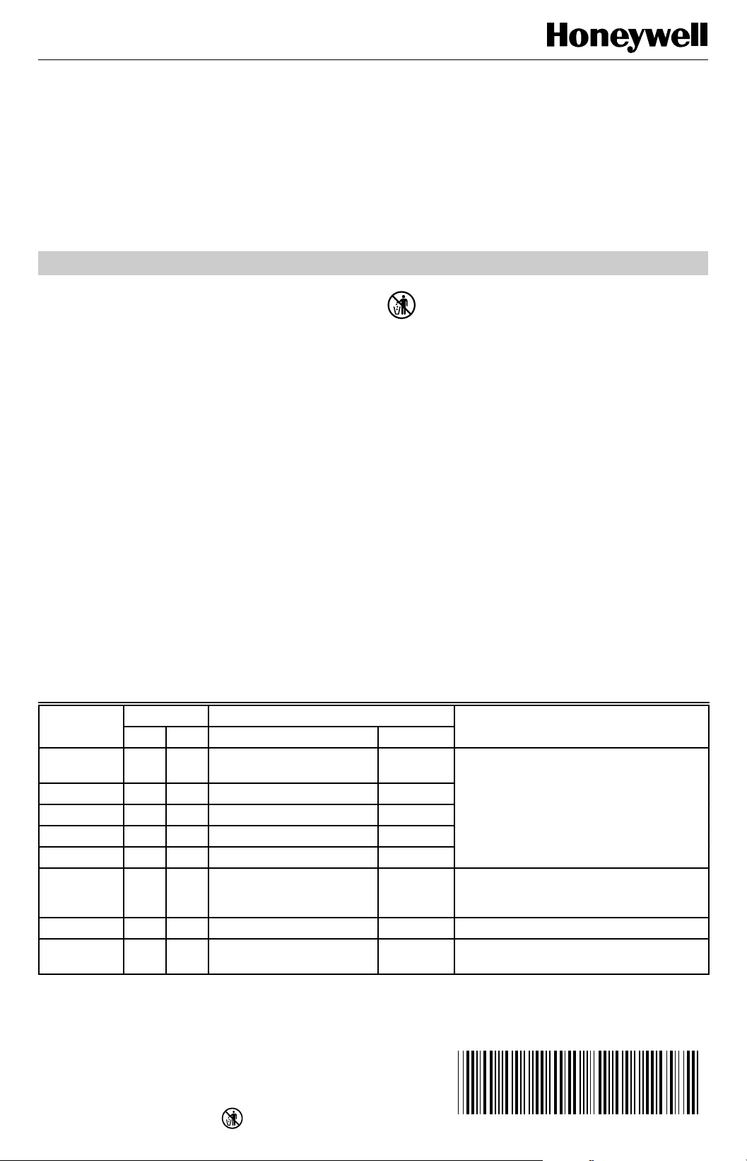
Table 1. Thermostat Models.
Stages Switching
Thermostat Heat Cool System Fan Application
T8602A 1 — — — Gas, oil or electric with independently
T8602B 1 — — ON-AUTO
T8602B 1 — HEAT-OFF —
T8602C 1 1 HEAT-OFF-COOL ON-AUTO
T8602D 1 1 HEAT-OFF-COOL-AUTO ON-AUTO
T8602C 1 1 HEAT-OFF-COOL ON-AUTO Fan operation in heating selectable for
TS8602A 1 — — — Millivolt heating system.
TS8602C
a
Available only in Canada.
a
1 1 HEAT-OFF-COOL ON-AUTO Millivolt heating and 24 Vac cooling
RECYCLING NOTICE
If this control is replacing a control that contains
mercury in a sealed tube, do
control in the trash. Contact your local waste
management authority for instructions regarding
recycling and the proper disposal of your old
control.
If you have any questions, call Honeywell Inc.
at 1-800-468-1502.
INSTALLATION
When Installing This Product…
1 Read these instructions carefully. Failure to follow
them could damage the product or cause a hazardous condition.
2 Check the ratings given on the product to make sure
the product is suitable for your application.
3 Installer must be a trained, experienced service
technician.
4 After installation is complete, check out product
operation as provided in these instructions.
5 Allow thermostat to warm to room temperature
before operating.
controlled fan.
thermostat or independent control; with O
and B terminals for changeover control.
system.
not
place your old
®U.S. Registered Trademark
Copyright © 1995 Honeywell Inc. • • All Rights Reserved
X-XX UL
Page 2
T8602A,B,C,D AND TS8602A,C Chronotherm
®
III FUEL SAVER THERMOSTATS
CAUTION
Disconnect power supply to prevent electrical
shock or equipment damage.
Location
Install thermostat and wallplate about 5 ft (1.5m) above the
floor in an area with good air circulation at room
temperature.
Do not install the thermostat where it can be affected by:
— drafts or dead spots behind doors, in corners, or
under cabinets.
— hot or cold air from ducts.
— radiant heat from sun or appliances.
— concealed pipes and chimneys.
— unheated (uncooled) areas such as an outside wall,
behind the thermostat.
If Replacing An Existing Thermostat
Turn off power to the thermostat at the furnace or boiler. A
two-transformer system can require turning off two
switches or disconnects. Remove any existing wallplate or
subbase from the wall. Write down the letter or number on
each wiring terminal, as the wire is removed, to avoid
miswiring later.
If New Installation
Run cable to the hole in the selected wall location, and pull
about 3 in. (76 mm) of wire through the opening. Colorcoded, 18 gauge thermostat cable with at least one
conductor for each wiring terminal is recommended.
Push excess wire back into the hole, and plug the hole
with nonhardening caulk, putty or insulation to prevent
drafts from affecting the thermostat operation.
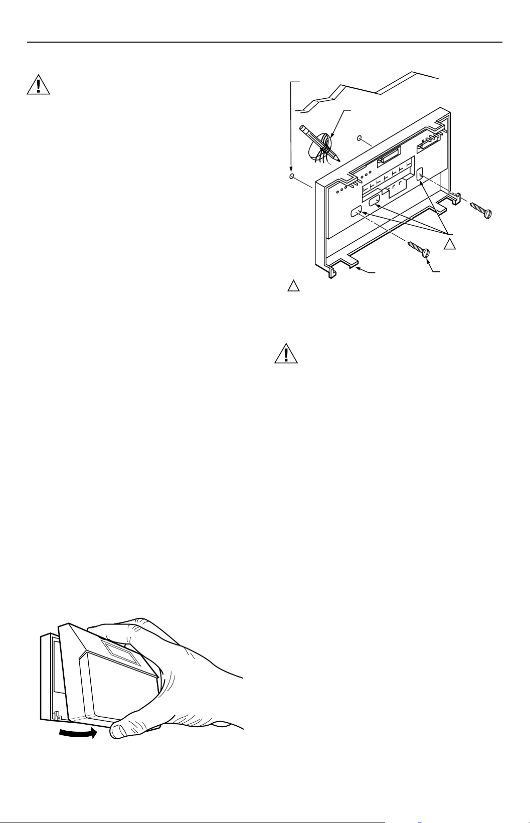
Mounting Wallplate
Remove thermostat from wallplate. See Fig. 1.
The wallplate does not require leveling for operation, but
for appearance only. The wallplate mounts directly onto
the wall with the screws included. Using the wallplate as a
template, with a pencil, mark two (of three) mounting
screw positions on the wallplate that fit the application. See
Fig. 2. Use a 3/16 in. bit to drill holes for the anchors.
Gently tap anchors into the holes until flush with the wall
surface. Thread wires through the center opening of the
wallplate. Mount the wallplate using the two screws
provided. Gently tighten the screws, level the top surface
of the wallplate, and then securely tighten the screws.
WALL
ANCHORS
(2)
WIRES THROUGH
WALL OPENING
USE TWO MOUNTING HOLES THAT
1
BEST FIT APPLICATION.
WALL
WALLPLATE
MOUNTING
HOLES (3)
1
MOUNTING
SCREWS (2)
M2917
Fig. 2. Mounting wallplate on wall.
Wiring
CAUTION
The TS8602A,C can only be used on 750 mV
heating applications. The TS8602A,C will not
function properly on 250 mV, 500 mV or 24 Vac
heating applications.
All wiring must comply with local electrical codes and
ordinances.
Disconnect power before wiring to prevent electrical shock
or equipment damage.
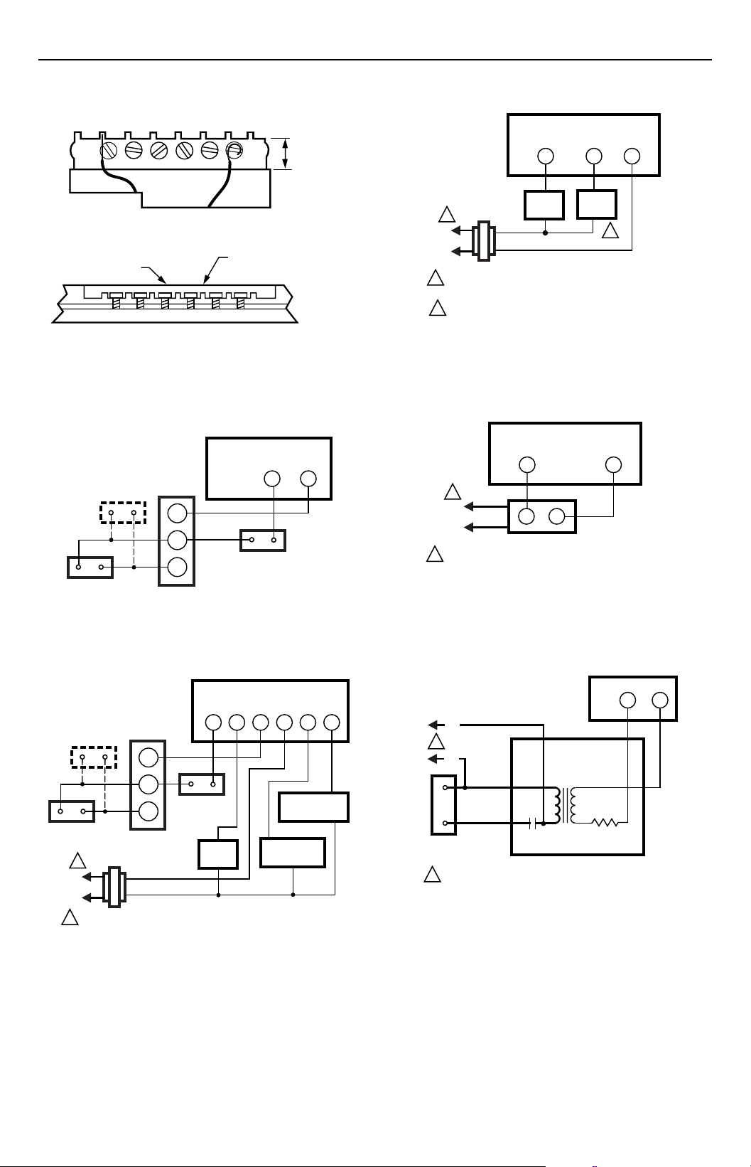
The shape of the terminal barrier permits insertion of
straight or conventional wraparound wiring connections.
Either method is acceptable.
Refer to Fig. 4 through 15 for typical wallplate and
thermostat hookups.
NOTE: • Keep all wiring restricted to the ribbed area
surrounding the terminals (Fig. 3) to assure
thermostat/wallplate contact.
• For single transformer applications, jumper
terminals R and RC for proper operation.
M2918
Fig. 1. Removing thermostat from wallplate.
69-0309—9 2
Page 3
T8602A,B,C,D AND TS8602A,C Chronotherm
®
III FUEL SAVER THERMOSTATS
FOR STRAIGHT
INSERTION –
STRIP 5/16 in. (8 mm)
FOR WRAPAROUND –
STRIP 7/16 in. (11 mm)
RESTRICT
WIRING TO
THIS AREA
FRONT VIEW OF
TERMINAL AREA
WIRING TO BE BELOW
THIS SURFACE
TOP SURFACE
OF SUBBASE
CROSS-SECTIONAL VIEW OF
TERMINAL AREA
M2927
Fig. 3. Keep wiring restricted to the ribbed area
surrounding terminals.
MILLIVOLT HEATING-ONLY
WALLPLATE
PILOTSTAT
CONTROL
(IF USED)
MILLIVOLTAGE
GENERATOR
TH
TH/
PP
PP
MILLIVOLTAGE
GAS CONTROL
W
R
LIMIT
CONTROL
M2931
Fig. 4. TS8602 in typical millivoltage heating circuit.
HEATING-ONLY WALLPLATE
W
GAS
1
L2
L1
(HOT)
1
POWER SUPPLY. PROVIDE DISCONNECT MEANS
AND OVERLOAD PROTECTION AS REQUIRED.
2
MODELS WITH ON-AUTO FAN SWITCH.
VALVE
G
FAN
RELAY
R
2
M2928
Fig. 6. T8602A,B heating-only circuit in a continuous
pilot gas system.
HEATING-ONLY WALLPLATE
W
1
L1
(HOT)
L2
1
POWER SUPPLY. PROVIDE DISCONNECT MEANS
AND OVERLOAD PROTECTION AS REQUIRED.
T
T
OIL PRIMARY
R
M2929
Fig. 7. T8602A,B heating-only circuit in an oil system.
MILLIVOLT HEATING-24Vac
COOLING WALLPLATE
PILOTSTAT
CONTROL
(IF USED)
TH
TH/
PP
LIMIT
PP
CONTROL
MILLIVOLTAGE
GENERATOR
1
L1
(HOT)
L2
1
POWER SUPPLY. PROVIDE DISCONNECT MEANS
AND OVERLOAD PROTECTION AS REQUIRED.
MILLIVOLTAGE
GAS CONTROL
FAN
RELAY
G
W
R
Y O
RC
CHANGEOVER
RELAY
COOLING
CONTACTOR
M2942
Fig. 5. TS8602C in typical millivoltage heating and
24 Vac cooling circuit.
HEATING ONLY WALLPLATE
R
W
BLACK
L1
(HOT)
1
L2
BLUE
RED
RESISTANCE
HEATER
1
POWER SUPPLY. PROVIDE DISCONNECT MEANS
AND OVERLOAD PROTECTION AS REQUIRED.
BIMETAL
SWITCH
SWITCH
HEATER
RED
WHITE
R841C
M2923
Fig. 8. T8602A,B heating-only circuit in an electric
baseboard or ceiling cable system.
69-0309—93
Page 4
T8602A,B,C,D AND TS8602A,C Chronotherm
®
III FUEL SAVER THERMOSTATS
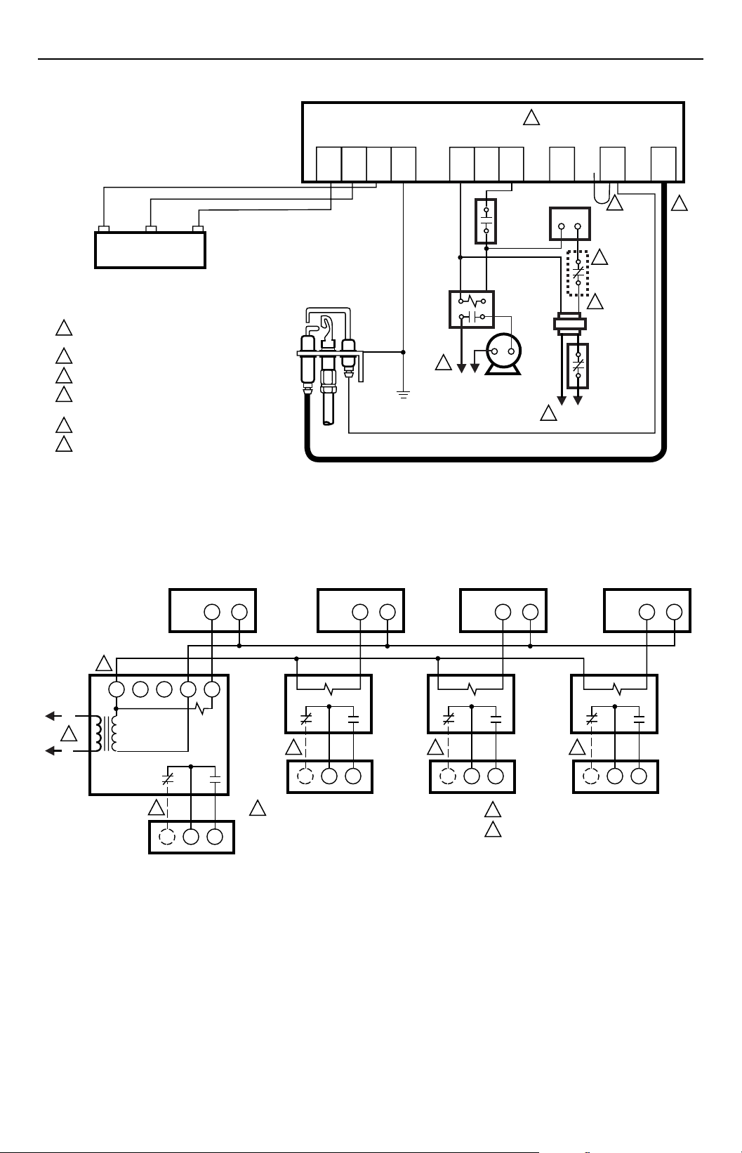
MV
DUAL VALVE COMBINATION
GAS CONTROL
POWER SUPPLY. PROVIDE DISCONNECT MEANS
1
AND OVERLOAD PROTECTION AS REQUIRED.
2
ALTERNATE LIMIT CONTROLLER LOCATION.
3
MAXIMUM CABLE LENGTH 3 FT (0.9M ).
4
CONTROLS IN 24V CIRCUIT MUST NOT BE
GROUND LEG TO TRANSFORMER.
5
LEAVE VENT DAMPER PLUG CONNECTED.
6
REMOVE JUMPER AND CONNECT SENSE
TERMINAL ON TWO ROD APPLICATION ONLY.
MV/PV
VR8345
MV
IGNITER
MV
MV/PV
PILOT GAS
SUPPLY
PV
SENSOR
GND
(BURNER)
PILOT
BURNER
GROUND
24V
GND
1
L1
(HOT)
CONTROLLER
S8610U
24V
L2
COMBUSTION
AIR BLOWER
MOTOR
5
TH-W
AIR
PROVING
SWITCH
COMBUSTION
AIR BLOWER
RELAY
VENT
DAMPER
PLUG
WR
L2
1
THERMOSTAT
4
LIMIT
CONTROLLER
L1
(HOT)
Fig. 9. T8602A,B heating-only circuit in a Honeywell Intermittent Pilot Gas Burner Ignition System.
SENSE
6
2
SPARK
3
M8600
L2
1
L1
(HOT)
2
R8239A1052
C
ZONE 1
VALVE OR
DAMPER
MOTOR
ZONE 1
HEATING ONLY WALLPLATE
W
RG
Y
W
3
R
ZONE 2
VALVE OR
DAMPER
MOTOR
ZONE 2
HEATING ONLY WALLPLATE
R
W
R8222B1067 R8222B1067
3 3 3
1
POWER SUPPLY. PROVIDE DISCONNECT MEANS
AND OVERLOAD PROTECTION AS REQUIRED.
ZONE 3
VALVE OR
DAMPER
MOTOR
ZONE 3
HEATING ONLY WALLPLATE
2
3
ZONE 4
HEATING ONLY WALLPLATE
R
W
R8222B1067
ZONE 4
VALVE OR
DAMPER
MOTOR
USE ONE R8239 FOR EVERY FOUR ZONES.
USE FOR 3-WIRE ZONE VALVE OR DAMPER.
W
M2921
R
Fig. 10. T8602A,B circuit for controlling incompatible or three-wire zone valves or dampers. Heating or cooling
equipment is operated by an end switch on the zone valve or motor, or by a thermostat in a master zone.
69-0309—9 4
Page 5

T8602A,B,C,D AND TS8602A,C Chronotherm
®
III FUEL SAVER THERMOSTATS
L2
1
L1
(HOT)
2
C
ZONE 1
HEATING ONLY WALLPLATE
R8239A1052
RG
Y
W
ZONE 1
VALVE OR
DAMPER
MOTOR
W
R
ZONE 2
HEATING ONLY WALLPLATE
R
W
ZONE 2
VALVE OR
DAMPER
MOTOR
ZONE 3
HEATING ONLY WALLPLATE
W
ZONE 3
VALVE OR
DAMPER
MOTOR
1
POWER SUPPLY. PROVIDE DISCONNECT MEANS
AND OVERLOAD PROTECTION AS REQUIRED.
2
USE ONE R8239 FOR EVERY FOUR ZONES.
ZONE 4
HEATING ONLY WALLPLATE
R
ZONE 4
VALVE OR
DAMPER
MOTOR
W
M2922
R
Fig. 11. T8602A,B circuit for controlling Honeywell or compatible two-wire zone valves or dampers. Heating or
cooling equipment is operated by an end switch on the zone valve or motor, or by a thermostat in a master zone.
HEATING-COOLING WALLPLATE
3 3
G
1
L1
(HOT)
L2
1
L1
(HOT)
L2
1
POWER SUPPLY. PROVIDE DISCONNECT MEANS
AND OVERLOAD PROTECTION AS REQUIRED.
2
PRIMARY CONTROL, SUCH AS GAS VALVE OR ELECTRONIC
IGNITION MODULE.
3
CURRENT DRAW FOR W OR Y PLUS G MUST BE
LESS THAN 1.6A.
W
HEATING
PRIMARY
CONTROL
FAN
RELAY
2
RC
R
Fig. 12. T8602C,D heating/cooling circuit in a
Y
COOLING
CONTACTOR
M2924
2
1
L1
(HOT)
L2
1
POWER SUPPLY. PROVIDE DISCONNECT MEANS
AND OVERLOAD PROTECTION AS REQUIRED.
2
PRIMARY CONTROL, SUCH AS GAS VALVE OR ELECTRONIC
IGNITION MODULE.
Fig. 13. T8602C,D heating/cooling circuit in a single
transformer system with gas heat/electric cooling and
electric furnace/electric cool. Controls fan in cooling
only (typical multi-speed fan application).
HEATING-COOLING WALLPLATE
G
W
HEATING
PRIMARY
CONTROL
FAN
RELAY
R
Y
COOLING
CONTACTOR
M2925
two-transformer (one for heating, one for
cooling) system with gas heat and electric cooling,
RC and R terminals.
69-0309—95
Page 6

T8602A,B,C,D AND TS8602A,C Chronotherm
®
III FUEL SAVER THERMOSTATS
HEATING-COOLING WALLPLATE
W
RELAY
1
L1
(HOT)
1
L1
(HOT)
L2
L2
POWER SUPPLY. PROVIDE DISCONNECT MEANS
1
AND OVERLOAD PROTECTION AS REQUIRED.
T
T
OIL PRIMARY
G
FAN
RELAY
Y
R
AIR
COND.
EQUIP.
M2926
Fig. 14. T8602C,D heating/cooling circuit in an oil
heating and electric cooling system. Heating trans-
former is in oil primary.
HEATING-COOLING WALLPLATE
2
3
Y
O
COOLING
DAMPER
W
HEATING
PRIMARY
CONTROL
G
FAN
RELAY
R
RC
B
HEATING
DAMPER
COOLING
CONTACTOR
RECOVERY
SELECTION
ADAPTIVE
INTELLIGENT ™
CONVENTIONAL
2
4A
SYSTEM
GRAVITY
AIR/WATER
HOT
WATER
GAS/OIL
WARM AIR
ELECTRIC
WARM AIR
1 SCREWS 2A, 2B AVAILABLE ON SOME MODELS ONLY.
2 SWITCH 4A FOR FAN OPERATION SELECTION AVAILABLE ON
SOME MODELS ONLY.
1A
OUT 1/2
TO 1 TURN
IN
IN IN
(FACTORY SETTING)
OUT 1/2
TO 1 TURN
1B
OUT 1/2
TO 1 TURN
OUT 1/2
TO 1 TURN
IN
3A
IN
(FACTORY SETTING)
OUT 1/2 TO 1 TURN
3A1A1B
2A 2B
TIME/TEMP
DISPLAY
24 HR IN
12 HR
o
C
o
F
1
2A 2B
OUT 1/2
TO 1 TURN
Fig. 16. Cycle rate adjustment.
IN
OUT 1/2
TO 1 TURN
M2082C
1
L1
(HOT)
L2
1
POWER SUPPLY. PROVIDE DISCONNECT MEANS
AND OVERLOAD PROTECTION AS REQUIRED.
2
FOR SYSTEMS WHERE THERMOSTAT MUST CONTROL
FAN DIRECTLY IN HEATING, SET FAN OPERATION SWITCH
TO ELEC POSITION. USE ONLY ONE TRANSFORMER, AND
JUMPER R AND RC.
3
FOR SINGLE TRANSFORMER SYSTEM, JUMPER R AND RC.
1
L1
(HOT)
L2
M319A
Fig. 15. T8602C heating/cooling circuit in a two-
transformer system (gas heating and electric cooling).
Includes O and B terminals for changeover control.
See Table 2 to set fan operation switch.
SETTING AND ADJUSTMENTS
Adjusting Cycle Rate
NOTE: MOST APPLICATIONS WILL NOT REQUIRE A
CHANGE IN CYCLE RATE.
The room air temperature will vary slightly from the comfort
temperature setting with the cycling of the furnace or air
conditioner. The equipment cycles off and on as the room
temperature approaches the setpoint.
The cycle rate of this thermostat is set for heating at six
cycles per hour and for cooling at three cycles per hour as
shipped from the factory. The cooling cycle rate cannot be
adjusted. On all models, except the TS8602, the heating
cycle rate can be adjusted by turning one or both cycle
rate adjustment screws located on the back of the thermostat. See Fig. 16. The screws should only be backed
out about one-half to one turn, or be turned in until tight.
Adaptive Intelligent Recovery™/
Conventional Recovery
The thermostat is factory-set for Adaptive Intelligent
Recovery™, but may be converted to conventional
recovery using screw 3A on the back of the thermostat as
in-dicated in Fig. 16.
69-0309—9 6
Page 7

T8602A,B,C,D AND TS8602A,C Chronotherm
SET
PRESENT
DAY/TIME
AHEAD
SET
PRESENT
DAY/TIME
DAY
®
III FUEL SAVER THERMOSTATS
With Adaptive Intelligent Recovery™, the room will reach
the comfort temperature at the exact time programmed
into the thermostat. The control temperature will increase
gradually, and turn the equipment on and off several times
to reach the comfort temperature slowly and on time.
There will be no wasted of energy associated with rapid
temperature changes and temperature overshoot.
With conventional recovery, the start time should be
programmed to be earlier than the desired comfort time. It
may require some trial and error to arrive at the best
starting time.
Setting Time/Temperature (Some Models)
The display readout may be converted between a 12 and
24 hour clock or °C and °F using screws 2A and 2B as
indicated in Fig. 16.
Setting Fan Operation
Some T8602C models include a fan operation switch on
the back of the thermostat on the lower left corner. See
Fig. 15. See Table 2 to determine correct setting of fan
operation switch.
CAUTION
The fan operation switch, which is available on
some T8602C models, is factory set to the NON
ELEC. position. If the system requires direct
thermostat control of the fan in heat mode, the
switch must be set to the ELEC. position. See
Table 2.
Table 2. T8602C Fan Operation Switch Setting.
Fan Operation
Fan Operation
Fan controlled
directly by
thermostat in heat
mode (typically
electric furnaces).
Fan has
independent
control in heat
mode (typically
gas, oil, millivolt
and some electric
furnaces).
Switch Setting
(4A) Comments
Set to ELEC.
position.
Use only one
system
transformer
jumper R and
RC.
Set to NON
ELEC. position
System may
have one or two
transformers;
if one
transformer,
jumper R and
RC.
IMPORTANT
The low battery warning will be displayed about
two months before the batteries are dead. When
the batteries are dead, the system will shut down.
After batteries are replaced, thermostat will
require reprogramming.
Mounting The Thermostat
Hang the thermostat on the tabs at the top of the base.
See Fig. 18A. Swing down and press on the lower edge
until the thermostat snaps into place. See Fig. 18B. Open
the cover, and tighten the captive mounting screws. See
Fig. 18C.
Setting Day and Time
Set the present day and time. When the thermostat is first
turned on, the display will read 1:00 PM and the room
temperature. It will go off for only a few seconds, then
begin to flash on and off.
Press .
Press TIME or to set the current
time.
Press .
Press to set the current day. Each press of the
DAY key advances the display one day.
If the display will not come on:
• Check mounting of thermostat to wallplate. If loose or
misaligned, remove thermostat and reinstall on the
wallplate, making sure it is firmly attached.
• Check to see that all the batteries are good and
installed correctly.
BACK
Installing Batteries
Power is supplied for the thermostat by three AA alkaline
batteries. Batteries are included with thermostat. Install
batteries in back of thermostat as shown in Fig. 17. The
display will flash 1:00 PM and room temperature.
When the batteries are going dead, the display will flash
REPL BAT. If device has system switch, set to OFF.
Remove the thermostat from the wall and install three new
AA alkaline batteries. We recommend Energizer®
batteries. Change batteries within approximately 30
seconds from the time the batteries are removed to
prevent program loss and the necessity to reprogram.
M2083
BATTERY
PLACEMENT
(NOTE CORRECT PLUS
AND MINUS DIRECTION)
Fig. 17. Battery placement.
69-0309—97
Page 8

T8602A,B,C,D AND TS8602A,C Chronotherm
®
III FUEL SAVER THERMOSTATS
A.
C.
PRESENT
DAY/TIME
HOLD
TEMP
B.
PM
MON
RETURN
PM
MON
RETURN
HEAT ON
TEMPERATURE
PRESENT
SETTING
TIME
LEAVE
AHEAD
BACK
WARMER
COOLER
PERIOD
CHANGE
TO LAST
PERIOD
SKIP
NEXT
RETURN
RUN
PROGRAM
SET
DAY
WAKE
SET
SLEEP
HEAT/COOL
HEAT ON
M2919
Fig. 18. Mounting thermostat on wallplate.
CHECKOUT
NOTE: On models without system or fan switch,
disregard instructions about moving the switch.
Heating
Move the system switch to HEAT and the fan switch to
AUTO. Press WARMER key until the setting is about 10°F
(6°C) above room temperature. Heating should start and
the fan should run (may be a short delay on forced air
systems). Press COOLER key until the setting is about
10°F (6°C) below room temperature. The heating equipment should shut off.
Cooling
CAUTION
Do not operate cooling if outdoor temperature is
below 50°F (10°C). Refer to manufacturer recommendations.
NOTE: When cooling setting is changed, thermostat will
wait up to five minutes before turning on the air
conditioner. This delay protects the compressor.
Move the system switch to COOL and the fan switch to
AUTO. Press COOLER key until the setting is about 10°F
(6°C) below room temperature. The cooling equipment
and fan should start. Press the WARMER key until the
setting is about 10°F (6°C) above room temperature. The
cooling equipment and fan should stop.
NOTE: On an AUTO changeover thermostat (T8602D),
the heating temperature must be set at least 3°F
(2°C) below the cooling temperature, or the
display will flash.
Fan
Move the system switch to OFF, and the fan switch to ON.
The fan should run continuously. When the fan switch is in
the AUTO position, the fan cycles with the heating or
cooling system.
Installer Self-Test (Optional)
Perform the following test as a check of all thermostat
functions. If thermostat does not respond as indicated,
replace the thermostat.
1 Press AHEAD and BACK keys at the same time.
While holding down the keys, all segments of the
display should be on. See Fig. 19.
2 Set system switch to OFF, where applicable. Press
AHEAD and BACK and PRESENT SETTING keys
at the same time to enter self-test.
3 Press each key as listed below, and look for
responses listed as key is held down and released.
REPL
AM
BAT
PM
SUN MON TUE WED THU FRI SAT COOL ON HEAT ON
WAKE LEAVE RETURN SLEEP TEMPORARY
Fig. 19. All segments on display.
SET
PT
M410C
M410C
69-0309—9 8
Page 9

T8602A,B,C,D AND TS8602A,C Chronotherm
LEAVE
®
III FUEL SAVER THERMOSTATS
System Press
Switch
Position
OFF 03 Blank
COOL or
AUTO
(with fan
in AUTO)
This
Key
CHANGE
TO LAST
PERIOD
SKIP
NEXT
PERIOD
PRESENT
SETTING
PRESENT
SETTING
PRESENT
SETTING
Look For This Response
Key
Down Key Released
07 Blank
15 Blank
15 Cooling, fan and
SYSTEM LED on.
15 Cooling, fan and
SYSTEM LED off.
OFF 06 Blank
WARMER
COOLER
02 Blank
05 Blank
AHEAD
BACK
04 Blank
01 Blank
First Digit
(cph At 50% On Time)
0 or 1 1
2 or 3 3
4 or 5 9
6 or 7 6
Cycle Rate Setting
Second
Digit
Clock
(Hr.) Degrees
Recovery
0 12 F Conventional
1 12 C Conventional
2 12 F Adaptive Intelligent
Recovery™
3 12 C Adaptive Intelligent
Recovery™
4 24 F Conventional
5 24 C Conventional
6 24 F Adaptive Intelligent
Recovery™
7 24 C Adaptive Intelligent
Recovery™
Setting
00 Blank
12 See note A
A
(Check
Each
RETURN
WAKE
position)
OFF 08 Blank
SLEEP
13 Microprocessor mask
DAY
SET
HEAT/COOL
PRESENT
SETTING
HEAT 14 Heating and SYSTEM
OFF 10 Blank
m
PRESENT
SETTING
1
PRESENT
SETTING
HOLD
TEMP
RUN
PROGRAM
no. and revision no.
09 Blank
14 Blank
LED on.
14 Heating and SYSTEM
LED off.
11 Normal operating
display
End Self-Test
1 For electric heat fan operation, the fan will operate with
m
the heating system when the fan switch is in AUTO.
A HEAT displayed when system switch is in HEAT,
COOL when in COOL, HEAT and COOL when in
AUTO, neither when in OFF. Also, a four-digit code is
displayed, with each digit explained as follows.
HH
GG
M1612
M1612
Third
Digit
Fourth
Digit
Thermostat
Type No.
System
Switch Position
0 C or D OFF or AUTO
1 B OFF
2 C or D COOL
4 C or D HEAT
5 A or B HEAT or no switch
Thermostat
Model
0 TS8602A;
System
Switch Position
Any position.
T8602A,B or C
1 T8602D HEAT, OFF, or COOL
3 T8602D AUTO
4 TS8602C; T8600, 01,
Any position.
or 03A,B or C
5 T8600, 01, or 03D HEAT, OFF, or COOL
7 T8600, 01, or 03D AUTO
This equipment is a Class B digital apparatus which complies with Canadian Radio Interference Regulations, CRC c.1374.
69-0309—99
Page 10

T8602A,B,C,D AND TS8602A,C Chronotherm
®
III FUEL SAVER THERMOSTATS
69-0309—9 10
Page 11

T8602A,B,C,D AND TS8602A,C Chronotherm
®
III FUEL SAVER THERMOSTATS
69-0309—911
Page 12

T8602A,B,C,D AND TS8602A,C Chronotherm
®
III FUEL SAVER THERMOSTATS
Home and Building Control
Honeywell Inc.
1985 Douglas Drive North
Golden Valley, MN 55422
Home and Building Control
Honeywell Limited-Honeywell Limitée
740 Ellesmere Road
Scarborough, Ontario
M1P 2V9
69-0309—9 12
69-0309—9 J.H. Rev. 7-95 Printed in Taiwan R.O.C.
Helping You Control Your World
QUALITY IS KEY
 Loading...