

TR29 Wall Mount Sensor Enclosure
INSTALLATION INSTRUCTIONS
APPLICATION
The TR29 wall mount sensor enclosure can be used with any
1/4-in.or 3/8-in. diameter probe sensor. Sensor can be
mounted inside of the enclosure or directly to the wall or duct
using the mounting clips supplied with the unit.
INSTALLATION
The TR29 is shipped with 2 mounting clips with adhesive strip
on the back. Choose the appropriate size mounting clip for
diameter probe you are using.
WALL OR DUCT MOUNT (Mounting Clip
only)
1. Choose the location for the mounting clip.
NOTE: Mounting surface for clip must be flat, with no
surface irregularities. The surface has to be
free of dust and grease.
2.
Remove the release liner from the clip adhesive surface.
3. Position the clip and firmly press the clip with adhesive
against the mounting surface.
4.
While holding the clip body against the mounting surface,
engage the sensor endpoint at the clip holding pawl.
5. Position the sensor body to be centered. See Fig. 1.
6. Attach the sensor leads as required.
COVER DISASSEMBLY
A snap-fit locking mechanism is used to attach the cover of
the wall module to its subbase. To disassemble the cover from
the subbase:
1. Insert a thin, flat blade screwdriver into each of the two
slots at the bottom of the module to release the two
locking tabs.
2. Tilt the cover out and away from the subbase to release
the top two locking tabs.
TR29 MOUNT
1. Mount the TR29 subbase.
NOTE: The TR29 can be mounted on a wall, on a
standard utility conduit box using No. 6 (3.5
mm) screws or on a 60 mm wall outlet box.
When mounting directly on a wall, use the type
of screws appropriate for the wall material.
2. Remove the release liner from the mounting clip adhesive surface.
3. Position the clip on the TR29 subbase as shown in
Figure 1.
4. Firmly press the clip with adhesive against the base.
5. While holding the clip body against the base, engage
the sensor endpoint at the clip holding pawl.
6. Position the sensor body to be centered. See Fig. 1.
7. Attach the sensor leads as required. Attach the TR29
cover to the base and tighten the cover screw.
8. Press the cover straight down onto the subbase until it
snaps into place.
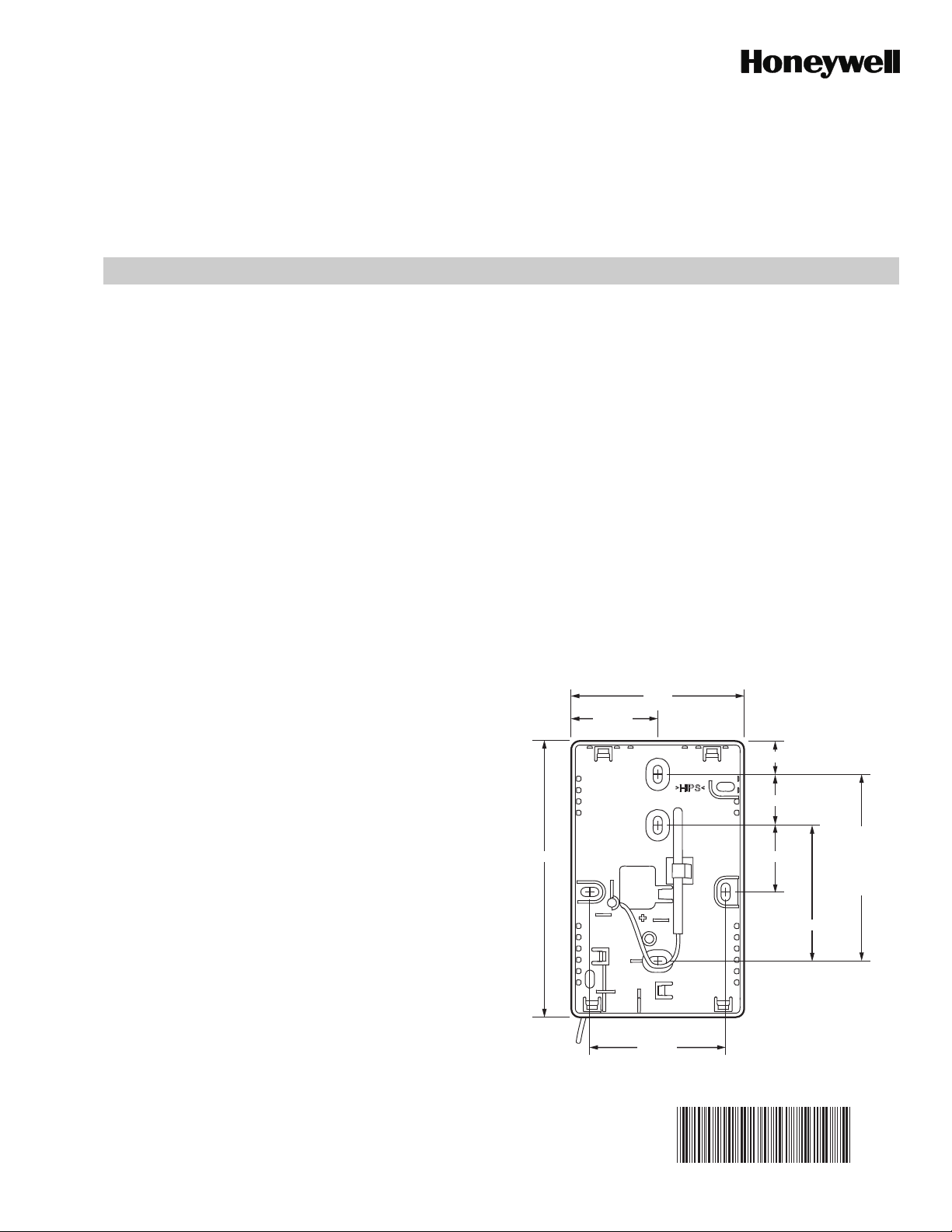
Fig. 1. Mounting clip and sensor installation.
3 (76)
1 1/2 (38)
9/16 (14)
13/16 (31)
STANDARD
7/8 (22)4 3/16 (122)
2 3/8 (60)
UTILITY
CONDUIT
BOX (2 X 4)
MOUNTING
HOLES
Automation and Control Solutions
Honeywell International Inc.
1985 Douglas Drive North
Golden Valley, MN 55422
Honeywell Limited-Honeywell Limitée
35 Dynamic Drive
Toronto, Ontario M1V 4Z9
customer.honeywell.com
® U.S. Registered Trademark
© 2010 Honeywell International Inc.
62-0315—03 E.K. Rev. 03-10
Printed in U.S.A.
2 3/8 (60)
M31317
62-0315-03
 Loading...