


TP970 and TP9600 Series
Pneumatic Thermostats
ENGINEERING DATA
Contents
Introduction .............................................................................................................................. 2
Fundamentals of
Thermostat Operation .............................................................................................................................. 2
General................................................................................................................. 2
Flapper-Nozzle Operation.................................................................................... 2
Valve Unit Operation ............................................................................................ 2
Low-Capacity, Single-Temperature
TP973A, B and TP9630 A, B
Thermostats .............................................................................................................................. 4
TP970A-D and TP9600A, B
High-Capacity, Single-Temperature
Thermostats .............................................................................................................................. 6
TP971A-C and TP9610A, B
High-Capacity, Dual-Temperature
Thermostats .............................................................................................................................. 7
TP972A and TP9620A High-Capacity,
Heating/Cooling Thermostat .............................................................................................................................. 10
General................................................................................................................. 4
Operation.............................................................................................................. 5
Direct Action.................................................................................................. 5
Reverse Action.............................................................................................. 5
General................................................................................................................. 6
Operation.............................................................................................................. 6
Direct Action.................................................................................................. 6
Reverse Action.............................................................................................. 7
TP971B and TP9610B ......................................................................................... 7
TP971C ................................................................................................................ 7
TP971A and TP9610A ......................................................................................... 7
Daytime Operation ............................................................................................... 8
Nighttime Operation ............................................................................................. 8
Manual DAY Override........................................................................................... 9
General................................................................................................................. 10
Operation.............................................................................................................. 12
TP974A Room
Temperature Sensor .............................................................................................................................. 12
General................................................................................................................. 12
Operation.............................................................................................................. 12
Copyright © 1997 Honeywell Inc. • All Rights Reserved
77-9382-1
TP970 AND TP9600 SERIES PNEUMATIC THERMOSTATS
INTRODUCTION
This Engineering Data sheet provides detailed information
on the operation of TP970 and TP9600 Ser ies Pneumatic
Thermostats (Thermostats). These Thermostats use the
force-balance design with high nozzle feedback for stability.
The TP970 and TP9600 Series includes the following
thermostat models:
— TP970A-D and TP9600A, B:
High capacity
Proportional control
Single temperature
— TP971A-C and TP9610A, B:
Dual temperature
Day/night control (automatic switchover through
diaphragm logic)
Two sensing elements
Individual setpoint control
— TP972A and TP9620A, B:
High capacity
Heating/cooling control (automatic switchover
through diaphragm logic)
Two sensing elements (one for heating control,
one for cooling control)
— TP973A, B and TP9630A, B:
Low capacity
Proportional control
Single temperature
— TP974A:
Room temperature sensor
Used as a remote temperature transmitter for the RP920
Pneumatic Controller
This Engineering Data sheet describes the TP973A, B and
TP9630A, B Thermostats first, because they are the
simplest.
FUNDAMENTALS OF THERMOSTAT
OPERATION
General
throttling range (TR) adjustment) has a fixed branchline
pressure (BLP) for each temperature within the temperature
and throttling range settings. The forces within the nozzleflapper-bimetal assembly always seek a balanced condition;
giving the same BLP for the same temperature regardless of
fluctuations in main air or the relative positions of the nozzle,
flapper, and bimetal.
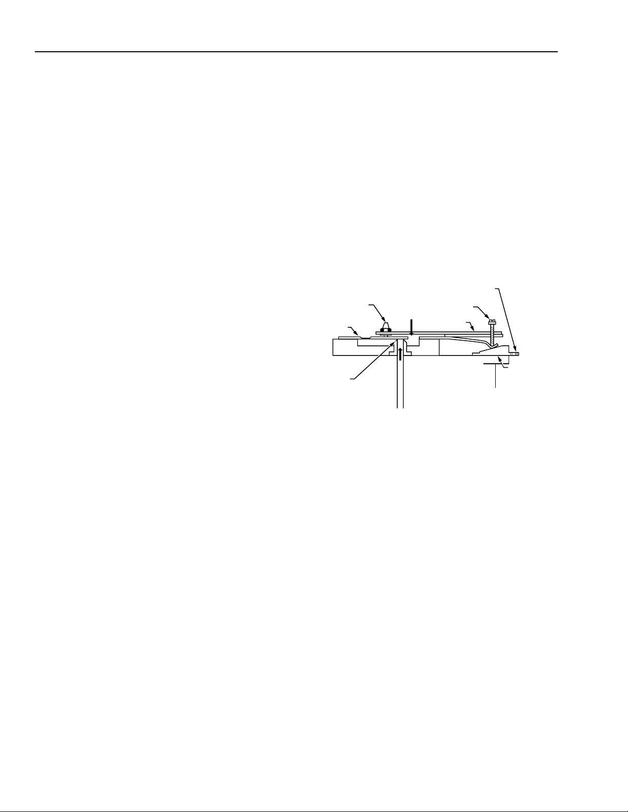
Flapper-Nozzle Operation
Flapper-nozzle operation is generally the same for all TP970
and TP9600 Thermostats. The Thermostat provides a
branchline air pressure that is a function of the ambient
temperature in the room or controlled space. As shown in
Figure 1, the force of the temperature-sensing bimetal acting
on one side of the flapper (Force A) is balanced by the
feedback force of the pilot pressure through the nozzle
acting on the other side of the flapper (Force B).
SETPOINT
THROTTLING RANGE
ADJUSTMENT
FORCE A
FLAPPER
NOZZLE
FORCE B
BIMETAL
IN BALANCED STATE,
FORCE B EQUALS FORCE A
Fig. 1. Flapper-Nozzle-Bimetal Assembly.
The position of the flapper over the nozzle changes and
creates a new pilot pressure when the bimetal force changes
(through temperature or setpoint change). This pilot pressure
feeds into the valve unit, which converts the low-capacity
pilot pressure to a high-capacity branchline change (see the
Valve Unit Operation section). Feedback at the nozzle
regulates the pressure to negate the effect of normal main
air supply fluctuations on the branch line.
Adjusting the throttling (proportioning) range changes the
flapper lever position. Moving the setpoint cam changes the
bimetal operating force and thus the setpoint.
KNOB
CALIBRATION
SCREW
SETPOINT
CAM
C6046
In force-balance design, two forces oppose each other until
they are equal, or balanced. The TP970 and TP9600 Series
Thermostats use the force of the bimetal to close the flapper
over the nozzle and the opposing force of the air pressure in
the nozzle chamber to lift the flapper (see the FlapperNozzle Operation section). When the forces are equal, a
force-balance condition exists.
The throttling range setting and the calibration reference
temperature determine the Thermostat span and calibration
point. At control point the nozzle-flapper-bimetal assembly
(acting through the calibration screw, setpoint cam, and the
77-9382—1
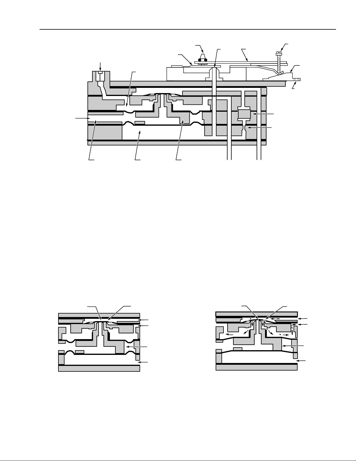
Valve Unit Operation
TP970, TP9600, TP971, TP9610, TP972, and TP9620
Thermostats use force-balance valve units to amplify airflow
and minimize air consumption without loss of required device
capacity. Figure 2 is a cross-section of a TP970 and TP9600
Thermostat showing the relationship of the valve unit to the
bimetal, nozzle, and other components.
2
TP790 AND TP9600 SERIES PNEUMATIC THERMOSTATS
POINT A
EXHAUST AIR
POINT B
MAIN LINE
BRANCH
LINE
PILOT AIR
C6049-1
NOTE: THE SEAL AT POINT A DOES NOT
ALLOW AIR TO EXHAUST.
VALVE
THROTTLING RANGE
ADJUSTMENT
FLAPPER
BLEED
BRANCHLINE
PRESSURE TAP
EXHAUST
BRANCHLINE
CHAMBER
PILOT
PILOT
CHAMBER
Fig. 2. Cross Section of TP970 and TP9600 Thermostat Showing Valve Unit and Airflow.
TP970, TP9600, TP971, TP9610, TP972, and TP9620
Thermostats are designed around a valve unit for flow
amplification rather than conventional pressure amplification.
Branchline chamber and pilot chamber design are such that
branch pressure is equal to nozzle pressure at a higher
capacity.
Figures 3, 4, and 5 are cross-sections of the valve unit only,
showing air passages and the pilot-branch diaphragm
relationship.
Figure 3 shows a valve unit in a strategic or balanced
condition. All the forces are equal; BLP equals the pilot-line
pressure.
No main air enters the branchline chamber and no exhaust
air leaves the branchline chamber. In this static condition,
the valve is sealed at both Points A and B, preventing airflow.
CALIBRATION
SCREW
SETPOINT
CAM
SETPOINT
KNOB
C6047-1
VALVE
NOZZLE
BRANCH LINE
BIMETAL
MAIN
LINE
FILTER
RESTRICTOR
Figure 4 shows the valve unit supplying air to the branch
line. This condition occurs when the bimetal sensing element
forces the Thermostat flapper to ward the nozzle, decreasing
the nozzle-flapper gap and increasing the pilot pressure.
The increased pilot pressure against the pilot diaphragm
overcomes the force of the BLP on the branchline
diaphragm. This change opens the valve unit at Point B,
allowing main air to flow into the branch line. BLP builds until
the pressure against the branch diaphragm again equals the
pressure against the pilot chamber diaphragm. The main
airflow then shuts off, bringing the valve unit into a balanced
condition at a new pressure.
With direct-acting bimetal sensors, a temperature increase
closes the nozzle-flapper gap; with reverse-acting bimetal
sensors, a temperature increase opens the nozzle-flapper
gap. The arrows in the air passages in Figure 4 show the
direction of airflow.
EXHAUST
POINT A
BRANCH
PILOT CHAMBER
POINT B
MAIN LINE
BRANCH
CHAMBER
VALVE
PILOT AIR
Fig. 3. Valve Unit Flow Amplifier in a
Balanced (Static) Condition.
LINE
C6048-1
Fig. 4. Valve Unit Shown with Pilot
Chamber Pressure Increased.
3
77-9382—1

TP970 AND TP9600 SERIES PNEUMATIC THERMOSTATS
Figure 5 shows the valve unit bleeding down the BLP. This
condition occurs when the bimetal sensing element relaxes
its force against the flapper, allowing the nozzle-flapper gap
to increase.
POINT A
VALVE
PISTON
EXHAUST
AIR
NOTE: THE SEAL AT POINT A DOES NOT
ALLOW AIR TO EXHAUST.
Fig. 5. Valve Unit Shown with Pilot
Chamber Pressure Decrease.
The reduction in pilot pressure against the pilot diaphragm
allows the BLP to overcome the pressure in the pilot
chamber. This change moves the valve piston down, sealing
off Point B and opening Point A. Branchline air bleeds off
until the pressure against the branchline diaphragm equals
the pressure against the pilot chamber diaphragm. When the
pressures become equal, the exhaust air is shut off at Point
A. The valve unit is again in a balanced condition at the new
pressure. The arrows in the air passages in Figure 5 show
the direction of airflow.
The preceding explanation of valve unit operation is very
important to understanding TP970, TP9600, TP971, TP9610,
TP972, and TP9620 operation. As can be seen from Figures
3, 4, and 5, pilot pressure changes affect BLP changes in
the same ratio. There is no pressure gain to amplify errors as
with other pneumatic Thermostats. Still, the main air supply
being switched through the valve unit, provides fast, high
capacity increase and decrease of BLP.
POINT B
MAIN LINE
BRANCH
LINE
VALVE
PILOT AIR
C6050-1
THROTTLING
RANGE
ADJUSTMENT
FLAPPER
BIMETAL
NOZZLE
AIR CONNECTION
FILTER AND
RESTRICTOR
SETPOINT
KNOB
CALIBRATION
SCREW
SETPOINT
CAM
SETPOINT
KNOB
C6051
Fig. 6. Basic TP973 and TP9630 Thermostat.
The TP973 and TP9630 are used on one- or two-pipe
systems. Connections are made to main and branch for twopipe applications (see Fig. 7). The main air connector is
plugged when used on one-pipe applications (Fig. 8). This
causes the Thermostat to operate like any other bleed-type
thermostat with a remote restrictor.
SETPOINT
KNOB
CALIBRATION
SCREW
FLAPPER
THROTTLING RANGE
ADJUSTMENT
BIMETAL
TP973A, B AND TP9630 A, B LOW CAPACITY, SINGLE-TEMPERATURE
THERMOSTA TS
General
The TP973A, B TP9630A, B (Fig. 6) are the simplest
Thermostats in the TP970 and TP9600 Series. Ever y other
model includes the basic TP973 and TP9630 assembly with
additions. Air going to the controlled device from the TP973
and TP9630 passes through an internal restrictor. The
TP973A and TP9630A are direct acting (signal pressure
increases as the temperature increases); the TP973B,
reverse acting (signal pressure increases as the temperature
decreases).
77-9382—1
NOZZLE
NOZZLE
CHAMBER
RESTRICTOR
MAIN LINE
CAM
SLOPE
BRANCH
LINE
BACKPLATE
TO CONTROLLED
DEVICE
SETPOINT
CAM
C6052
Fig. 7. TP973 and TP9630 Operating Section.
4

TP790 AND TP9600 SERIES PNEUMATIC THERMOSTATS
SETPOINT
KNOB
CALIBRATION
SCREW
CAM
SLOPE
BACKPLATE
SETPOINT
CAM
C6053
FLAPPER
NOZZLE
NOZZLE
CHAMBER
RESTRICTOR
MAIN LINE
THROTTLING RANGE
ADJUSTMENT
BIMETAL
TO CONTROLLED
DEVICE
Fig. 8. TP973 and TP9630 Operating
Section—Main Port Capped.
Operation
Direct Action
Refer to Figures 7 and 8. On a temperature rise, the flapper
is forced toward the nozzle by the action of the temperaturesensing bimetal, which reduces the flapper-nozzle gap. The
change in the flapper-nozzle gap allows less air to escape
from the nozzle, thus increasing the pressure in the nozzle
chamber as well as the branch line. The controlled device is
thereby positioned to maintain the controlled space to the
desired temperature.
The Thermostat provides a BLP that is a function of ambient
temperature. The force from the bimetal acting on the flapper
is balanced by the feedback force of the BLP acting on the
opposite side of the flapper through the nozzle. If the
setpoint knob is changed to a new setting, the opposing
forces in the lever system go out of balance and the room
ambient temperature changes to rebalance the lower
system.
For example, if the setpoint cam is moved to a higher
temperature setting, the point of the lever system that rides
the slope of the cam lowers (direct-acting device) due to this
cam slope. As a result, the bimetal reduces its force applied
to the flapper. The reduced force causes the BLP to bleed
down and a heating valve to open. Heat is introduced to the
space until the forces of the bimetal are again in equilibrium
with the opposing force (8 psi [55 kPa] times the area of the
nozzle at the flapper). A reduction in setpoint causes the
reverse to happen.
The calibration screw allows for matching the bimetal start
position with the indicated setting on the setpoint cam to
achieve an 8 psi (55 kPa) BLP at the indicated setpoint.
The TR adjustment (Fig. 9) provides a means for changing
the effective length of the bimetal. When the TR adjustment
is moved over the nozzle, the force from the bimetal is
exerted directly over the nozzle and a narrow TR, or very
high sensitivity, results. For example, a 1°F (0.56°C) change
in temperature results in a 5 psi (34 kPa) BLP change.
When the TR adjustment is moved toward the end of the
bimetal away from the nozzle, the effective force output of
the bimetal is reduced. This reduction requires a greater
temperature change at the bimetal to throttle the flapper over
the nozzle. The result is a wider TR or very low sensitivity; for
instance, a 1°F (0.56°C) change in temperature results in
only a 1 psi (7 kPa) BLP change.
Reverse Action
Refer to Figures 7 and 8. On a temperature rise, the flapper
is forced away from the nozzle by the action of the
temperature-sensing bimetal, which increases the flappernozzle gap. The change in the flapper-nozzle gap allows
more air to escape from the nozzle, thus decreasing the
pressure in the nozzle chamber as well as the branch line.
The controlled device is thereby positioned to maintain the
controlled space to the desired temperature.
THROTTLING
BRANCHLINE
PRESSURE
GAGE TAP
FLAPPER
NOZZLE
RANGE
ADJUSTMENT
BIMETAL
BRANCH
LINE
MAIN
LINE
CALIBRATION
SCREW
FILTER
RESTRICTOR
Fig. 9. Cross Section of TP973 and TP9630 Thermostat.
5
SETPOINT
CAM
SETPOINT
KNOB
C6054
77-9382—1

TP970 AND TP9600 SERIES PNEUMATIC THERMOSTATS
The Thermostat provides a BLP that is a function of ambient
temperature. The force from the bimetal acting on the flapper
is balanced by the feedback force of the BLP acting on the
opposite side of the flapper through the nozzle. If the
setpoint knob is changed to a new setting, the opposing
forces in the lever system go out of balance and the room
ambient temperature changes to rebalance the lower
system.
For example, if the setpoint cam is moved to a higher
temperature setting, the point of the lever system that rides
the slope of the cam rises (reverse-acting device) due to this
cam slope. As a result, the bimetal increases its force
applied to the flapper. The increased force causes the BLP
to build up and a cooling valve to open. Cooling is introduced
to the space until the forces of the bimetal are again in
equilibrium with the opposing force (8 psi [55 kPa] times the
area of the nozzle at the flapper). A reduction in setpoint
causes the reverse to happen.
The calibration screw allows for matching the bimetal start
position with the indicated setting on the setpoint cam to
achieve an 8 psi (55 kPa) BLP at the indicated setpoint.
The TR adjustment provides a means for changing the
effective length of the bimetal. When the TR adjustment is
moved over the nozzle, the force from the bimetal is exerted
directly over the nozzle and a narrow TR, or very high
sensitivity, results. For example, a 1°F (0.56°C) change in
temperature results in a 5 psi (34 kPa) BLP change.
When the TR adjustment is moved toward the end of the
bimetal away from the nozzle, the effective force output of
the bimetal is reduced. This reduction requires a greater
temperature change at the bimetal to throttle the flapper over
the nozzle. The result is a wider TR or very low sensitivity; for
instance, a 1°F (0.56°C) change in temperature results in
only a 1 psi (7 kPa) BLP change.
BRANCH LINE
PRESSURE GAGE PORT
THROTTLING RANGE
ADJUSTMENT
FLAPPER
VALVE UNIT
BIMETAL
SETPOINT KNOB
NOZZLE
CALIBRATION
SCREW
SETPOINT
KNOB
SETPOINT
CAM
C6055
Fig. 10. TP970 and TP9600 High Capacity
Pilot Operated Thermostat.
NOTE: TP970C1000 (direct acting) and TP970D1008
(reverse acting) Thermostats have extended
throttling ranges of 5 to 20°F (2.5 to 10°C) for
energy conservation applications. The extended
throttling range allows for a Zero Energy Band
(ZEB) between sequenced heating and cooling
modes.
TP970A-D AND TP9600A, B HIGHCAPACITY, SINGLE-TEMPERATURE
THERMOSTA TS
General
The TP970 and TP9600A, B Thermostats (Fig. 10) are the
basic TP973 with a valve unit added for greater capacity to
control valve or damper actuators in heating or cooling
systems.
TP970A, B, C, D and TP9600A, B devices are bimetalelement, pilot-operated, two-pipe, proportioning pneumatic
Thermostats. The TP970A, C and TP9600A are direct acting
(BLP increases as temperature increases). The TP970B, D
and TP9600B are reverse-acting (BLP decreases as
temperature increases).
Operation
Direct Action
Refer to Figure 11. On a temperature rise, the flapper is
forced toward the nozzle by the action of the bimetal. The
force of the bimetal acting on the flapper is balanced by the
feedback force of the pilot pressure in the nozzle chamber
acting in an opposing direction. This action varies the
flapper-nozzle gap, which in turn causes an increased
pressure in the pilot line. The change in pilot pressure is
routed to the flow amplifier that converts the low capacity
pilot pressure signal to a high capacity branchline flow at the
same pressure.
For a more detailed discussion, refer to the Valve Unit
Operation section.
77-9382—1
6

TP790 AND TP9600 SERIES PNEUMATIC THERMOSTATS
SETPOINT KNOB
THROTTLING RANGE
ADJUSTMENT
FLAPPER
NOZZLE
NOZZLE
CHAMBER
RESTRICTOR
MAIN LINE
BIMETAL
CALIBRATION
SCREW
VALVE
UNIT
PILOT LINE
FLOW
AMPLIFIER
BRANCH LINE
SETPOINT
CAM
C6056-1
Fig. 11. Operating Sections of TP970A, C and TP9600A
(Direct Acting).
Reverse Action
Refer to Figure 11. On a temperature rise, the flapper is
forced away from the nozzle by the action of the bimetal. The
force of the bimetal acting on the flapper is balanced by the
feedback force of the pilot pressure in the nozzle chamber
acting in an opposing direction. This action varies the
flapper-nozzle gap, which in turn causes a decreased
pressure in the pilot line. The change in pilot pressure is
routed to the flow amplifier that converts the low capacity
pilot pressure signal to a high capacity branchline flow at the
same pressure.
For a more detailed discussion, refer to the Valve Unit
Operation section.
TP971A-C AND TP9610A, B HIGHCAPACITY, DUAL-TEMPERATURE
TP971A and TP9610A
On the TP971A and TP9610A direct-acting Thermostats (Fig.
12), the daytime bimetal controls the system when the main
air pressure is 13 psi (90 kPa). The nighttime element
controls the system when the main air pressure reaches 18
psi (124 kPa). Models are available with switchover
pressures of 16 to 21 psi (110 to 145 kPa) and 20 to 25 psi
(138 to 172 kPa).
NIGHT BIMETAL
NIGHT THROTTLING
RANGE ADJUSTMENT
DAY THROTTLING
RANGE ADJUSTMENT
THROTTLING RANGE
ADJUSTMENT
FLAPPER
DAY/NIGHT
LOGIC CIRCUIT
Fig. 12. TP971 and TP9610 Day/Night Thermostat.
NIGHT SETPOINT
INDICATOR
DAY BIMETAL
BRANCH LINE
PRESSURE GAGE PORT
BIMETAL
NOZZLE
AIR CONNECTION
FILTER AND
RESTRICTOR
NIGHT SETPOINT
KNOB
DAY
SETPOINT KNOB
CALIBRATION
ADJUSTMENT
NIGHT
SETPOINT CAM
DAY
SETPOINT
KNOB
VALVE UNIT
C6057
THERMOSTATS
The TP971A, B, C and TP9610A, B Thermostats feature day
and night sensing elements with individual setpoint
adjustments for day/night control of heating and air
conditioning systems. The Thermostat cover is removable for
adjusting the nighttime setpoint. All TP971 and TP9610
Thermostats have a manual override lever (DAY/AUTO)
which allows the occupant to change the Thermostat
operation from night cycle to day cycle. The Thermostat can
be made tamper proof by cutting off the manual override
lever with a side cutter. The complete manual override lever
assembly can be removed and replaced if desired (see
TP970 and TP9600 Series Pneumatic Thermostats Service
Data 75-7134).
TP971B and TP9610B
The TP971B and TP9610B are the same as the TP971A and
TP9610A except that they are reverse acting.
TP971C
The TP971C is a direct-acting, three-pipe Thermostat. The
third pipe, a secondary branch line, is a switched line
providing pilot control of auxiliary equipment. Switchover
pressure is 13 psi (90 kPa) for daytime operation and 18 psi
(124 kPa) for nighttime operation. The TP971C is typically
used in conjunction with unit ventilator systems requiring
Day/Night/Warm-up cycles.
The secondary branch line is used with a pneumatic/electric
(P/E) switch to start and stop the supply fan on the night
cycle. The secondary branch line has full main air pressure
on the night cycle and daytime main air pressure on the day
cycle.
7
77-9382—1

TP970 AND TP9600 SERIES PNEUMATIC THERMOSTATS
Daytime Operation
Figure 13 shows airflow through the Thermostat during
daytime operation. The main air pressure is at the lower,
daytime operating pressure of 13 psi (90 kPa).
Air enters the Thermostat through the main line, passes
through a screen, then diverts into the valve unit and through
the multistage filter. The arrows in Figure 13 show main air
traveling to Logic Module A, which is closed because the
adjustable spring is set to open only at the higher nighttime
pressure. Main air passes through the integral restrictor, into
the pilot chamber of the valve unit, and in to Logic Module B.
The spring holds Port B1 open because there is no air
pressure against the top of the diaphragm of Logic Module
B. This action allows air to pass through Port B1 to the 13 psi
(90 kPa) (DAY) nozzle-flapper. The Thermostat now operates
on a daytime cycle at the daytime setpoint. The valve unit
operation is identical to that described in the Valve Unit
Operation section.
S
SECONDARY
BRANCH
LOGIC MODULE A
1
Nighttime Operation
In Figure 14, the main air pressure is at 18 psi (124 kPa) for
nighttime operation. The airflow, shown by arrows, is the
same as the daytime cycle up to Logic Module A and Logic
Module B. The main air pressure, 18 psi (124 kPa), is now
enough to overcome the spring-loaded diaphragm in Logic
Module A. Because the manual override lever is in the AUTO
position, the air passes through Logic Module A, and then
through Logic Modules C and D. This air pressure forces the
diaphragm of Logic Module B downward, closing Port B1
and allowing air to pass through Port B2. The airflow then
passes to the 18 psi (124 kPa) (NIGHT) nozzle-flapper. In
this condition, the Thermostat operates on a nighttime cycle.
Valve unit flow amplifier operation is identical to that
described in the Valve Unit Operation section.
DAY/AUTO LEVER
MANUAL DAY
LOGIC
MODULE C
LOGIC
MODULE D
MAIN LINE
SPRING
B BLEED 1
SPRING
LOGIC
MODULE B
S
S
F
FILTER
BRANCH LINE
R
RESTRICTOR
PILOT
CHAMBER
VALVE
UNIT
DOTTED LINES INDICATE THE SECONDARY
1
BRANCH LINE INTEGRAL TO THE TP971C
Fig. 13. TP971 and TP9610 Operation on Day Cycle—Main Air Pressure 13 psi (90 kPa).
BLEED 2
B
DIAPHRAGM
PORT B2
PORT B1
18 PSI (124 kPa)
NIGHT
13 PSI (90 kPa)
DAY
C6058-1
77-9382—1
8

S
SECONDARY
BRANCH
TP790 AND TP9600 SERIES PNEUMATIC THERMOSTATS
DAY/AUTO LEVER
1
LOGIC MODULE A
LOGIC
MODULE C
MANUAL DAY
LOGIC
MODULE D
SPRING
BLEED 1
B
MAIN LINE
S
S
F
FILTER
BRANCH LINE
R
RESTRICTOR
PILOT
CHAMBER
Fig. 14. TP971 and TP9610 Operation on Nighttime Cycle—Main Air Pressure 18 psi (124 kPa).
Manual DAY Override
Manual DAY Override is shown in Figure 15. With main air
pressure at the 18 psi (124 kPa) (NIGHT) setting, airflow
applies pressure to Logic Modules A, C, and D. However,
because the DAY/AUTO lever has been manually positioned
to DAY, Logic Module D is shut off, stopping airflow. Air
pressure is bled from Logic Module B through Bleed 2, and
the diaphragm moves up to open Port B1 and close Port B2.
This condition allows an airflow path to the 13 psi (90 kPa)
(DAY) nozzle-flapper and closes the airflow path to the 18
psi (124 kPa) (NIGHT) nozzle-flapper. Thus, the Thermostat
works on a daytime cycle even though the main air supply
pressure is at its normal night cycle main air pressure of 18
psi (124 kPa).
The 18 psi (124 kPa) pressure on the diaphragm of Logic
Module C holds the manual DAY/AUTO lever in position. If
the occupant fails to return the override lever, the lever
returns automatically when the system main air pressure is
reduced to 13 psi (90 kPa). This change returns the
Thermostat to its normal operation and automatic logic
switchover.
The secondary branch line operates with the manual DAY/
AUTO lever position as follows:
1. System in normal daytime operation, 13 psi (90 kPa)
main air pressure (Fig. 13 dotted lines).
2. Move the manual DAY/AUTO lever to the DAY position.
It snaps back to AUTO because there is no air
pressure on logic switch C (Fig. 13).
The secondary branch line is always at the main air pressure
when the system operates in a daytime mode; the P/E switch
contacts are closed and the supply fan is operating.
BLEED 2
VALVE
UNIT
SPRING
LOGIC
MODULE B
1
B
DIAPHRAGM
PORT B2
PORT B1
DOTTED LINES INDICATE THE SECONDARY
BRANCH LINE INTEGRAL TO THE TP971C
18 PSI (124 kPa)
NIGHT
13 PSI (90 kPa)
DAY
C6059-1
During normal nighttime operation conditions (Fig. 14):
1. The system is in normal nighttime operation mode;
main and secondary branchline air pressure is at 18
psi (124 kPa). The secondary branch line is also at 18
psi (124 kPa).
2. Since the P/E switch contacts open at any pressure
over 15 psi (103 kPa), the supply fan is off.
3. The manual DAY/AUTO lever is in the AUTO position
because operation is under normal nighttime
conditions (Fig. 14).
The secondary branch line is at the night main air pressure
of 18 psi (124 kPa) when the system is operating in a normal
nighttime mode. The P/E switch contacts are open and the
supply fan is off because the pressure in the secondary
branch is over 15 psi (103 kPa).
For night occupancy and daytime control:
1. Push the DAY/AUTO switch to the DAY position. This
opens the nozzle-bleed on the secondary branch line
(Fig. 15).
2. The DAY/AUTO lever stays in the DAY position
because of the air pressure on Logic Module C (Fig.
15).
3. The main air pressure in the secondary branch line
bleeds down through the secondary branch nozzle.
The secondary branchline restrictor maintains normal
night system pressure in the rest of the Thermostat.
However, airflow is now diverted to operate the nozzleflapper on the DAY mode sensing element (Fig. 15).
9
77-9382—1

TP970 AND TP9600 SERIES PNEUMATIC THERMOSTATS
MAIN LINE
S
SECONDARY
BRANCH
S
S
SPRING
F
FILTER
BRANCH LINE
1
LOGIC MODULE A
B
R
RESTRICTOR
BLEED 1
SB
NOZZLE
PILOT
CHAMBER
Fig. 15. TP971 and TP9610 Operation, DAY/AUTO Lever Manually Set to
DAY Position—Main Air Pressure 18 psi (124 kPa).
When the air supply system returns to its normal daytime
pressure, the DAY/AUTO lever is spring returned to the
AUTO position and the Thermostat returns to normal
operation. The occupant can also return the system to
normal operation by manually switching the DAY/AUTO lever
to AUTO.
LOGIC
MODULE C
VALVE
UNIT
HEATING THROTTLING
RANGE ADJUSTMENT
SPRING
LOGIC
MODULE B
DAY/AUTO LEVER
MANUAL DAY
LOGIC
MODULE D
BLEED 2
B
DIAPHRAGM
PORT B2
PORT B1
1
DOTTED LINES INDICATE THE SECONDARY
BRANCH LINE INTEGRAL TO THE TP971C
HEATING
BIMETAL
HEATING SETPOINT
KNOB FOR TP972A1036
(55-75°F (13-24°C) RANGE)
18 PSI (124 kPa)
NIGHT
13 PSI (90 kPa)
DAY
C6060-1
In the preceding situation, the P/E switch contacts are
closed. This is because the secondary BLP is under 15 psi
(103 kPa); the DAY/AUTO lever is held in the DAY position
by pressure on Logic Module C; and the Thermostat uses its
daytime bimetal because the airflow through Logic Module
D is closed off.
TP972A AND TP9620A HIGH-CAPACITY,
HEATING/COOLING THERMOSTA T
General
The TP972A and TP9620A (Fig. 16) are high-capacity, twopipe, proportioning pneumatic Thermostats with two bimetal
sensing elements.
COOLING THROTTLING
RANGE ADJUSTMENT
THROTTLING RANGE
ADJUSTMENT
FLAPPER
HEATING/COOLING
LOGIC CIRCUIT
THERMOMETER
POST
BRANCH LINE
PRESSURE GAGE PORT
BIMETAL
NOZZLE
COOLING
BIMETAL
AIR CONNECTION
FILTER AND
RESTRICTOR
SETPOINT
KNOB (TAB
REMOVED FOR
TP972A1036)
CALIBRATION
ADJUSTMENT
NIGHT
SETPOINT KNOB
VALVE UNIT
COOLING
SETPOINT
KNOB
C6061-1
Fig. 16. TP972A and TP9620A Cross Section Showing
Adjustments and Modular Construction.
77-9382—1
10

TP790 AND TP9600 SERIES PNEUMATIC THERMOSTATS
The TP972A and TP9620A have one setpoint adjustment
knob that controls both heating and cooling bimetals. Each
bimetal has an independent throttling range adjustment
(Fig. 16). The cooling bimetal of the TP972A and TP9620A
controls when the two-pressure air supply is at the lower of
the two pressures; the heating bimetal of the TP972A and
TP9620A controls when air supply pressure increases to the
higher of the two pressures. Typical values for the twopressure supply systems are 13/18 psi (90/124 kPa),
16/21 psi (110/145 kPa), and 20/25 psi (138/172 kPa).
Figures 17 and 18 are schematic representations of the
TP972A and TP9620A airflow paths for heating and cooling
control. Operation is the same as that for the TP971 and
SPRING
LOGIC
MODULE A
B
BLEED 1
MAIN LINE
S
F
FILTER
R
RESTRICTOR
PILOT
CHAMBER
TP9610 except for the logic modules, the manual override,
and the independent setpoint adjustment. Cooling control
requires a lower pressure in the main air supply. Figure 17
shows the workings and traces the air path within the
TP972A and TP9620A when it is controlling with the cooling
bimetal.
NOTE: The TP972A2036, A2168, and A2176 and TP9620A
limited-control-range Thermostats have separate,
concealed setpoints for heating and cooling and
limit the heating control point to a maximum of
75°F (24°C).
18 PSI (124 kPa)
WINTER
13 PSI (90 kPa)
SUMMER
SPRING
LOGIC
MODULE B
DIAPHRAGM
PORT B2
PORT B1
S
BRANCH LINE
MAIN LINE
S
S
BRANCH LINE
VALVE
UNIT
Fig. 17. TP972A and TP9620A Operation on Cooling Cycle—Main Air Pressure 13 psi (90 kPa).
SPRING
LOGIC
MODULE A
18 PSI (124 kPa)
WINTER
DIAPHRAGM
PORT B2
PORT B1
13 PSI (90 kPa)
SUMMER
F
FILTER
R
RESTRICTOR
B
BLEED 1
PILOT
CHAMBER
VALVE
UNIT
SPRING
LOGIC
MODULE B
C6062-1
C6063-1
Fig. 18. TP972A and TP9620A Operation on Heating Cycle—Main Air Pressure at 18 psi (124 kPa).
11
77-9382—1

TP970 AND TP9600 SERIES PNEUMATIC THERMOSTATS
Operation
Main air enters through the main air passage. Filtered air
goes to Logic Module A and into the pilot chamber of the
valve unit flow amplifier (see arrows in Fig. 17). When the air
reaches Logic Module A, it cannot pass because the springloaded diaphragm is adjusted to pass only 18 psi (124 kPa)
of air. In this condition, no air pressure is applied to the
diaphragm of Logic Module B and it stays in the up position,
allowing air to pass from the pilot chamber through Port B1.
This air is routed on to the flapper-nozzle of the cooling
bimetal and the Thermostat operates in a cooling mode. The
spring-loaded diaphragm of Logic Module B stays open until
air pressure is applied from Logic Module A.
When main air enters the Thermostat at 18 psi (124 kPa), as
previously described for the cooling cycle, the spring of
Logic Module A is overcome and air passes through the
Module. The air pressure is applied to the diaphragm of
Logic Module B, closing off Port B1, and opening Port B2.
Now the air is directed to the flapper-nozzle of the heating
bimetal and the Thermostat controls in the heating mode.
TP974A ROOM TEMPERATURE
SENSOR
General
FLAPPER
NOZZLE
EXTERNAL
RESTRICTOR
MAIN
LINE
BIMETAL
FILTER
RESTRICTOR
BACKPLATE
TO
CONTROLLED
DEVICE
C6065
Fig. 20. Cross Section of TP974A—One-Pipe Application.
Operation
Figure 21 shows a TP974A used with a direct-acting
RP920A Controller for control of a normally open heating
valve. A fall in temperature at the TP974A lowers the signal
to the RP920A. The RP920A responds by decreasing the
BLP to the valve to admit more hot water to the heating coil.
TP974A
The TP974A (Fig. 19, 20) is a bimetal-element, proportioning
temperature sensor for either two- or one-pipe applications.
The sensor bimetal is direct acting (signal pressure
increases as the temperature increases). The TP974A is
factory calibrated for 50 to 100°F (10 to 38°C), for a fixed
span of 50°F (28°C). This span is equal to a corresponding
pressure change of 12 psi (83 kPa) for 3 to 15 psi (21 to
103 kPa). The TP974A has no setpoint adjustment and the
TR is factory preset.
FLAPPER
NOZZLE
BRANCH SIGNAL
PRESSURE
(TO INDICATION
GAGE OR CONTROL)
BIMETAL
FILTER
RESTRICTOR
BACKPLATE
MAIN
LINE
C6064
Fig. 19. Cross Section of TP974A—Two-Pipe Application.
M
21
RP920A
SUPPLY N.O.
3
(DA)
Fig. 21. Typical TP974A Operation.
C6066
Home and Building Control
Honeywell Inc.
Honeywell Plaza
P.O. Box 524
Minneapolis MN 55408-0524
77-9382—177-9382—1 R. F. 10-97
Home and Building Control
Honeywell Limited-Honeywell Limitée
155 Gordon Baker Road
North York, Ontario
M2H 3N7
Printed in U.S.A. on recycled
paper containing at least 10%
post-consumer paper fibers.
12
 Loading...