

Page 1
Honeywell
T841D,E
Heating-Cooling Thermostats
INSTALLATION INSTRUCTIONS
Installation Instructions for the Trained Service Technician.
APPLICATION
T841 Thermostats provide 24 Vac control of multistage
heating and cooling systems using manual changeover.
The T841D controls 1-stage heat and 2-stage cool and the
T841E controls 2-stage gas heat and 1-stage cool. The
T841D,E, provide HEAT-OFF-COOL system switching
and AUTO-ON fan switching.
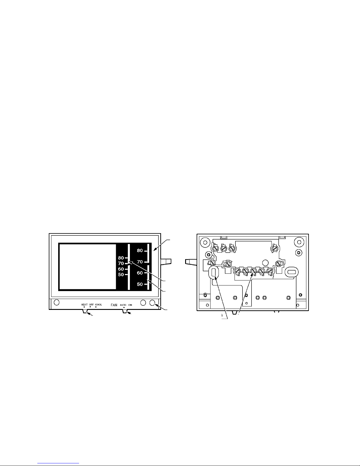
Test holes are provided on the front of the thermostat to
accommodate test meter probes without removing the
thermostat from the wall. Remove the cover of the
thermostat to expose the test holes, which are labeled to
correspond with terminals on back of the thermostat. See
Fig. 1.
Table 1. Thermostat Features.
Order Number LEDs Terminal Designations System Switch Fan Switch
Fig.
T841D CHECK, HI SPD, LO SPD R,G,W,B,L,X,Y1,Y2,O HEAT-OFF-COOL AUTO-ON 2
T841E HI, LOW R,G,W1,B,W2,Y HEAT-OFF-COOL AUTO-ON 3
F R O N T O F D E V IC E B A C K O F D E V IC E
-S YSTEM SWITCH
FAN SWITCH
THERMOMETER
SETPOINT
SCALE
- LED (UP
TO THREE)
MOUNTING
HOLES (4)
WIRING TERM INAL 1
(UP TO 12)
COVER
Fig. 1. External view of T841.
OPERATION
The T841E stages of heat make sequentially as the
temperature drops. Make refers to the mercury switch
initiating a call for heat or cool.
There is about 1 °F (0.6°C) between stages so the second
stage (auxiliary heat) makes only when the first stage
cannot handle the load. This 1°F is the interstage differen
tial. The T841D stages of COOL-ON make sequentially as
the temperature rises.
The light emitting diodes (LED) indicators light on certain
thermostats when something specific happens within the
system. Refer to the following list when the LED lights:
HI: Stage two of heat is operating.
LOW: Stage one of heat is operating.
CHECK: System needs to be checked. See heating
system instructions for specific meaning.
HI SPD: Stage two of cooling is operating.
LO SPD: Stage one of cooling is operating.
LEDs are not field replaceable.
®U.S. Registered Trademark
Copyright © 1997 Honeywell Inc.
All Rights Reserved
69-1066
Page 2
T841D,E HEATING-COOLING THERMOSTATS
® RECYCLING NOTICE
This control contains mercury in a sealed tube.
Do not place control in the trash at the end of its
useful life.
If this control is replacing a control that contains
mercury in a sealed tube, do not place your old
control in the trash.
Contact your local waste management authority for
instructions regarding recycling and the proper
disposal of this control, or of an old control
containing mercury in a sealed tube.
INSTALLATION
When Installing this Product...
1. Read these instructions carefully. Failure to follow
them could damage the product or cause a hazard
ous condition.
2. Check the ratings given in the instructions and on
the product to make sure the product is suitable for
your application.
3. Installer must be a trained, experienced technician.
4. After installation is complete, check out product
operation as provided in these instructions.
CAUTION
1. Disconnect power supply to prevent electrical
shock or equipment damage.
2. Keep wire length to a minimum and run wires
as close as possible to the thermostat.
3. Do not short across coil terminals on relay. This
can burn out the thermostat heat anticipator.
4. Never install more than one wire per terminal
unless factory-supplied jumper with spade
terminal is used.
Location
Locate the thermostat about 5 ft (1.5m) above the floor in
an area with good air circulation at average temperature.
Do not mount the thermostat where it may be affected by:
— drafts, or dead spots behind doors and in corners.
— hot or cold air from ducts.
— radiant heat from sun, appliances or fireplaces.
— concealed pipes and chimneys.
— unheated (uncooled) areas such as an outside wall
behind the thermostat.
This thermostat is a precision instrument and was carefully
adjusted at the factory. Handle carefully.
Mounting and Wiring
The T841 can be mounted directly to a wall or horizontal
outlet box. Choose the method that best fits your
installation.
In replacement applications, check the existing thermo
stat wires for cracked or frayed insulation. Replace any
wires in poor condition. All wiring must comply with local
codes and ordinances.
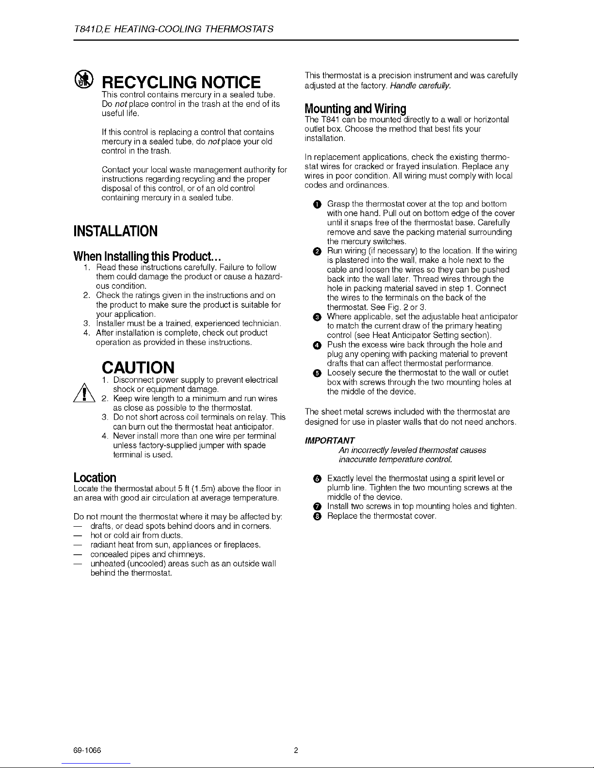
O Grasp the thermostat cover at the top and bottom
with one hand. Pull out on bottom edge of the cover
until it snaps free of the thermostat base. Carefully
remove and save the packing material surrounding
the mercury switches.
e Run wiring (if necessary) to the location. If the wiring
is plastered into the wall, make a hole next to the
cable and loosen the wires so they can be pushed
back into the wall later. Thread wires through the
hole in packing material saved in step 1. Connect
the wires to the terminals on the back of the
thermostat. See Fig. 2 or 3.
© Where applicable, set the adjustable heat anticipator
to match the current draw of the primary heating
control (see Heat Anticipator Setting section).
Q Push the excess wire back through the hole and
plug any opening with packing material to prevent
drafts that can affect thermostat performance.
0 Loosely secure the thermostat to the wall or outlet
box with screws through the two mounting holes at
the middle of the device.
The sheet metal screws included with the thermostat are
designed for use in plaster walls that do not need anchors.
IMPORTANT
An incorrectly leveled thermostat causes
inaccurate temperature control.
0 Exactly level the thermostat using a spirit level or
plumb line. Tighten the two mounting screws at the
middle of the device.
0 Install two screws in top mounting holes and tighten.
0 Replace the thermostat cover.
69-1066 2
Page 3

T841D,E HEATING-COOLING THERMOSTATS
Fig. 2. Internal schematic and typical wiring diagram for T841D.
Provides 1-stage heating and 2-stage cooling control.
Fig. 3. Internal schematic and typical wiring diagram for T841E.
Provides 2-stage heating and 1-stage cooling control.
3 69-1066
Page 4

T841DE HEATING-COOLING THERMOSTATS
SETTINGS
CHECKOUT
Heat Anticipator Setting
The heating anticipator is adjustable on the T841D and
the first stage heating on the T841E. Move the adjustable
indicator to match the current draw of the heating primary
control, or the anticipator setting of the old thermostat.
See Fig. 4.
NOTE: When T841D is used with heat pump systems,
set heat anticipator at 1.2.
Temperature Setting
Move the setpoint lever to the desired control point on the
temperature scale.
System Switch Setting
The system switching positions control the system
operation as described below:
HEAT: Heating system is automatically controlled by
the thermostat. Cooling system is off.
OFF: Both the heating and cooling systems are off.
If the fan is at AUTO position, the cooling fan
is also off.
COOL: Cooling system is automatically controlled by
the thermostat. Heating system is off.
Fan Switch Setting
AUTO: Fan operates in response to thermostat in
cooling.
ON: Fan operates continuously.
RATING OF
PRIMARY CONTROL
Heating
Move the system switch on the thermostat to HEAT and
the fan switch to AUTO. Move the setpoint lever to about
10°F (6°C) above room temperature. Heating should start.
The fan should start after a short delay. Move the setpoint
lever about 10°F (6°C) below room temperature. Heating
should shut off. The fan will shut off after a short delay.
Cooling
A CAUTION
Do not operate cooling if outdoor temperature is
below 50°F (10°C). Refer to the manufacturer
recommendations.
Move the system switch on the thermostat to COOL and
the fan switch to AUTO. Move the setpoint lever about
10°F (6°C) below room temperature. Cooling and fan
should start (see NOTE above). Move the setpoint lever
about 10°F (6°C) above room temperature. Cooling and
fan should shut off.
Fan
Move the system switch to OFF, and the fan switch to ON.
The fan should run continuously. Move the fan switch to
AUTO. In this position, the fan operates in response to the
thermostat in both heating and cooling.
Fig. 4. Adjustable heat anticipator indicator.
Honeywell
Home and Building Control
Honeyw e ll Inc.
Honeyw e ll Plaza
P.O. Box 524
M in neapolis, M N 55408-0524
Home and Building Control Helping You Control Your World®
Honeyw ell Lim ited-H o n eywell L im itée
155 Gordo n B ake r Road
N o rth Y o rk, Ontario
M 2H 2C9
69-1066 C.H. 1-97 Printed in Mexico www.honeyweN.com /yourhome
 Loading...