

Page 1
T8411R Electronic
Heat Pump Thermostat
INSTALLATION INSTRUCTIONS
APPLICATION
The T8411R Heat Pump Thermostat provides 24V control
of a two-stage heating and one-stage cooling heat pump
system with manual changeover from heat to cool. First
stage heating and cooling cycle rates are fixed at 3 cph.
Second stage heating cycle rate is selectable at 3, 6, or
9 cph. Temperature indication can be set for °F or °C.
The T8411R Heat Pump Thermostat is powered directly
from the system transformer. Setpoints are held permanently
in memory and retained during power outages.
The T8411R includes a thermostat, wallplate (for wiring
and mounting thermostat) and owner’s guide. A 7 3/8 in.
(188 mm) x 5 3/4 in. (146 mm) Decorator Cover Plate (for
covering wall marks) is available separately. Order
Honeywell part no. 209650A (Premier White
RECYCLING NOTICE
If this control is replacing a control that contains
mercury in a sealed tube, do
control in the trash.
Contact your local waste management authority for
instructions regarding recycling and the proper
disposal of an old control containing mercury in a
sealed tube.
®
).
not
place your old
INSTALLATION
When Installing this Product…
1. Read these instructions carefully. Failure to follow
them could damage the product or cause a hazardous condition.
2. Check the ratings given in the instructions and on
the product to make sure the product is suitable for
your application.
3. Installer must be a trained, experienced service
technician.
4. After installation is complete, check out product
operation as provided in these instructions.
CAUTION
Disconnect power supply before beginning wiring
to prevent electrical shock or equipment damage.
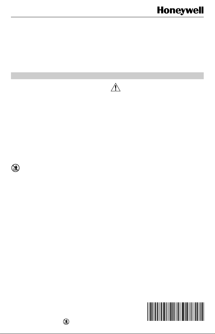
Location
Install the thermostat about 5 ft (1.5m ) above the floor in
an area with good air circulation at average temperature.
See Fig. 1. Do not install the thermostat where it can be
affected by:
— drafts or dead spots behind doors and in corners.
— hot or cold air from ducts.
— radiant heat from the sun or appliances.
— concealed pipes and chimneys.
— unheated (uncooled) areas such as an outside wall
behind the thermostat.
This thermostat is a precision instrument and was carefully
adjusted at the factory.
Handle it carefully.
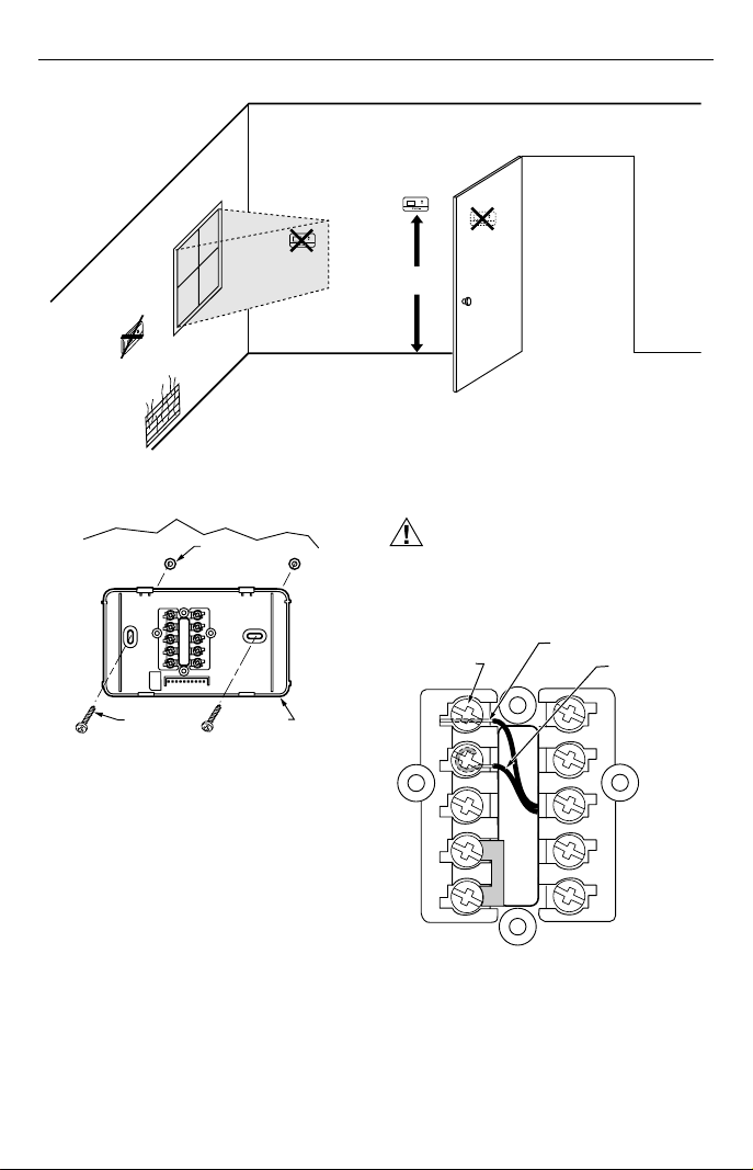
Mounting Wallplate
IMPORTANT
Level for appearance only. The thermostat
functions normally even when not level.
Mount wallplate, T8411R and the screws provided
(see Fig. 2) as follows:
1. Position the wallplate at the desired location on the
wall.
2. Use a pencil to mark the mounting holes.
3. Remove the wallplate from the wall and drill two 3/16
in. holes in the wall (if drywall) and two 7/32 in. holes
for firmer material such as plaster or wood. Gently
tap the anchors (provided) into the holes until flush
with the wall.
4. Position the wallplate over the holes.
5. Pull the thermostat wire through the entrance hole
on the wallplate.
®U.S. Registered Trademark
Copyright © 1997 Honeywell Inc. • • All Rights Reserved
X-XX UL
69-1037
Page 2
T8411R ELECTRONIC HEAT PUMP THERMOSTAT
NO
NO
Fig. 1. Typical location of thermostat.
WALL
MOUNTING
SCREWS (2)
WALL
ANCHORS (2)
WALLPLATE
M12202
Fig. 2. Mounting wallplate to wall.
Wiring
IMPORTANT
Use 18-gauge thermostat cable for proper wiring.
All wiring must comply with local electrical codes and
ordinances.
YES
5 FEET
[1.5 METERS]
The shape of the terminals permits insertion of straight or
wraparound wiring connections; either method is acceptable.
See Fig. 3.
NO
M11338
CAUTION
Disconnect the power supply to prevent electrical
shock or equipment damage.
FOR STRAIGHT INSERTION
TERMINAL
SCREW
STRIP 5/16 IN. (8 MM)
FOR WRAPAROUND
STRIP 7/16 IN. (11 MM)
G
L
C
R
W1
Y
W2
E
B
O
M11334
69-1037
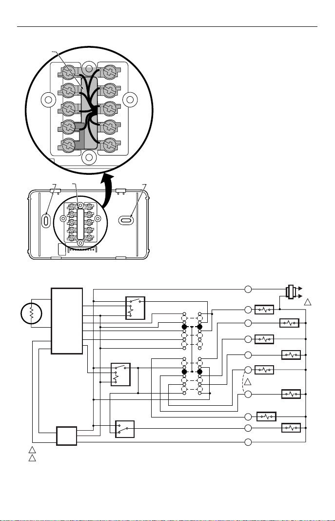
Fig. 3. Wiring connections.
2
Page 3
T8411R ELECTRONIC HEAT PUMP THERMOSTAT
KEEP WIRING IN
SHADED AREA
MOUNTING
SCREW HOLE
G
C
R
W1
Y
WIRING ENTRANCE
HOLE
L
W2
E
B
O
MOUNTING
SCREW HOLE
M11331
NOTE: Restrict all wiring to the shaded area between the
terminals. See Fig. 4.
Refer to Fig. 5 for typical wiring hookup. A letter code is
located near each terminal for identification.
1. Loosen the terminal screws on the wallplate and
connect the system wires. See Fig. 5.
2. Securely tighten each terminal screw.
3. Push the excess wire back into the hole.
4. Plug the hole with nonflammable insulation to
prevent drafts from affecting the thermostat.
Mounting Thermostat To Wallplate
1. Engage the tabs at the top of the thermostat and
wallplate.
2. Swing down the thermostat and press the lower
edge of the thermostat onto the wallplate to latch.
See Fig. 6.
Fig. 4. Restrict wiring to shaded area.
THERMISTOR
SENSOR
THERMOSTAT
LOGIC
POWER
SUPPLY
POWER SUPPLY. PROVIDE DISCONNECT MEANS AND OVERLOAD PROTECTION AS REQUIRED.
1
2
REMOVE JUMPER, WHEN SUPPLIED, FOR SYSTEMS WITH SEPERATE HEATING COMPRESSOR CONTACTOR (W1 SEPARATE FROM Y).
STAGE 2 RELAY
STAGE 1 RELAY
FAN SWITCH
ON
AUTO
SYSTEM
SWITCH
EM. HT.
HEAT
OFF
COOL
Fig. 5. T8411R two-stage heat and one-stage cool wiring diagram with manual changeover.
R
AUXILARY
HEAT RELAY
W2
L
CHANGEOVER
VALVE HEAT
B
O
COMPRESSOR
CONTACTOR
Y
2
W1
EMERGENCY
HEAT RELAY
E
G
C
RELAY
CHANGEOVER
VALVE COOL
COMPRESSOR
CONTACTOR
HEAT
FAN RELAY
M11333
L1
(HOT)
L2
1
3
69-1037
Page 4

T8411R ELECTRONIC HEAT PUMP THERMOSTAT
DASHED LINES INDICATE TABS
ON BACK OF THERMOSTAT
F
A
N
Auto On
Cool O
S
Y
S
T
E
ff
M
H
eat Em
. H
t.
A
ENGAGE TABS AT TOP OF THERMOSTAT
WITH SLOTS ON MOUNTING PLATE.
F
A
N
A
u
to
O
n
S
Y
o
l O
S
T
E
ff
M
H
e
a
t E
m
. H
t.
PRESS LOWER EDGE OF
B
CASE TO LATCH.
M11332
Fig. 6. Mounting thermostat to wallplate.
OPERATION
Setting FAN and SYSTEM Switches
Fan and system settings are controlled manually by using
the switches located at the bottom of the thermostat case.
See Fig. 7.
FAN Switch
Fan switch settings are as follows:
On: The fan runs continuously. Use for improved air
circulation.
Auto: Normal setting for most homes. The fan starts
and stops with the equipment.
Slide the switch in the bottom left corner of the thermostat
to select the desired fan setting.
SYSTEM Switch
System switch settings control thermostat operation as
follows:
Cool: Thermostat controls the cooling system.
Off: Both heating and cooling are off.
Heat: Thermostat controls the heating system.
Em Ht: Thermostat cycles Auxiliary Heat (W2) and
Emergency Heat Relay (E) as needed to maintain
setpoint. Terminal L is energized continuously.
(Fault heat relay is on continuously.) Cooling system
is off. Compressor is de-energized.
Slide the switch in the bottom right corner of the thermostat to select the desired system setting.
TEMPERATURE DISPLAY
INCREASE SETTING
DECREASE SETTING
F
A
N
Auto On
S
C
Y
ool O
S
T
FAN SWITCH
SYSTEM SWITCH
E
M
ff
H
eat E
m
. H
t.
M11330
Fig. 7. Temperature display and system switches.
Em Ht and Aux Ht Indications
The indicator points to either Emergency Heat (Em Ht)
or Auxiliary Heat (Aux Ht) when these modes are active.
Em Ht: The indicator points to Em Ht when the
SYSTEM switch is set at Em Ht.
Aux Ht: The indicator points to Aux Ht when auxiliary
backup heat is needed to help handle the heating
load.
INDICATOR
Em Ht
Aux Ht
Set
Room
M10287
Set Temperature Setpoint
NOTE: Temperature setpoint range is 40°F to 99°F
(4°C to 39°C).
69-1037
4
Page 5

T8411R ELECTRONIC HEAT PUMP THERMOSTAT
The temperature setpoint and the room temperature are
shown separately on the digital display. The ▼ indicator
points to Set when the temperature setpoint is displayed
and to Room when the room temperature is displayed.
INDICATOR
Set
To set temperature setpoint:
1. Select heat or cool by sliding the SYSTEM switch
in the lower right corner of the thermostat to the
desired mode. See Fig. 7.
2. To display the setpoint temperature on the
digital display, press either the ▲ or ▼ key once.
The temperature setpoint is displayed for approximately five seconds as the indicator points to Set
and flashes.
3. To increase the setpoint temperature, press the ▲
key. Press once to change the setpoint one
degree; press and hold to change the setpoint
several degrees.
4. To decrease the setpoint temperature, press the
▼ key.
ROOM TEMPERATURE
Room
SETPOINT TEMPERATURE
M11248
M11249
M11250
M11247
Setting °F/°C Indication and Heat Cycle Rate
NOTES: To save changes to the °F/°C indication and the
heat cycle rate, all seven steps must be
completed.
In installer setup mode steps 2. through 5., each
press of the ▲ key momentarily displays 01 and
each press of the ▼ key momentarily displays
02. When the keys are released, these two-digit
codes are no longer displayed.
To set the °F/°C indication and heat cycle rate:
1. If the room temperature is displayed in °F, set the
temperature setpoint to 52°F. If the room temperature is displayed in °C, set the temperature setpoint
to 11°C.
2. Press the ▲ ▼ keys simultaneously for more than
two seconds to light all segments on the display and
to enter installer setup mode. When the keys are
released, a two-digit software code is displayed
(code displayed may vary).
M11252
M11255
Optional System Checkout
CAUTION
When the heat or cool outputs are turned on, the
five-minute off-timer safety feature is bypassed.
When in steps
used to turn heat or cool outputs on. Change the
system switch setting to test heat or cool outputs.
No action takes place if the system switch is in
the Off position.
The following examples of system settings show a two
digit software code on the display. The code shown is only
an example; codes may vary.
System setting at Heat:
To turn heat on, press the ▼ key.
M11469
2.
and 3. only, the ▼ key can be
To turn auxiliary heat on, press the ▼ key.
Aux Ht
M11470
To turn auxiliary heat off, press the ▼ key a third time.
M11469
To turn heat off, press the ▼ key a fourth time.
M11255
System setting at Cool:
To turn cool on, press the ▼ key.
M11256
To turn cool off, press the ▼ key.
M11251
M11255
3. Press the ▲ key. Factory information is displayed.
Information displayed varies by model. This
information is only for factory use.
5
69-1037
Page 6

T8411R ELECTRONIC HEAT PUMP THERMOSTAT
4. Press the ▲ key again to display °C or °F. 1. Slide the SYSTEM switch to Heat and the FAN
M11259
5. Press the ▼ key to change the °C or °F indication.
M11260
NOTE: Stage one heat and cool cycle rates are fixed at
3 cph. Only stage two heat cycle rates are
selectable.
6. Press the ▲ key to display the heat cycle rate of 3,
6, or 9. If the desired cycle is displayed, press the ▲
key to exit the installer setup mode. To change the
heat cycle rate, press the ▼ key to scroll between 3,
6, and 9. Stop scrolling when the desired rate is
displayed.
M11261
7. Press the ▲ key to save all changes, exit installer
setup mode and return to normal control.
NOTE: After exiting installer setup mode, change the
setpoint to the desired room temperature.
CHECKOUT
Heating
CAUTION
To avoid possible compressor damage, allow the
compressor to remain off for five minutes before
restarting.
switch to Auto.
2. Press and hold the ▲ key to raise the temperature
setting several degrees above the room temperature. After approximately five minutes, the heating
equipment should start.
3. Press the ▼ key to lower the temperature setting
below the room temperature. Heating equipment
should stop.
Cooling
CAUTION
Do not operate cooling if outdoor temperature is
below 50°F (10°C). Refer to equipment manufacturer instructions.
To avoid possible compressor damage, allow
the compressor to remain off for five minutes
before restarting.
1. Slide the SYSTEM switch to Cool and the FAN
switch to Auto.
2. Press the ▼ key to lower the temperature setting
several degrees below the room temperature. After
approximately five minutes, the cooling equipment
and fan should start.
3. Press the ▲ key to raise the temperature setting
above the room temperature. Cooling system should
shut down.
Fan
1. Slide the SYSTEM switch to Off and the FAN switch
to On. The fan should run continuously.
2. Slide the FAN switch to Auto. The system turns the
fan on or off with the equipment.
Make certain all equipment responds properly to the
thermostat.
69-1037
6
Page 7

T8411R ELECTRONIC HEAT PUMP THERMOSTAT
7
69-1037
Page 8

T8411R ELECTRONIC HEAT PUMP THERMOSTAT
Home and Building Control
Honeywell Inc.
Honeywell Plaza
P.O. Box 524
Minneapolis, MN 55408-0524
69-1037 J.S. 5-97 Printed in Mexico www.honeywell.com/yourhome
69-1037
Home and Building Control
Honeywell Limited-Honeywell Limitée
155 Gordon Baker Road
North York, Ontario
M2H 3N7
8
Helping You Control Your World
®
 Loading...