

Page 1
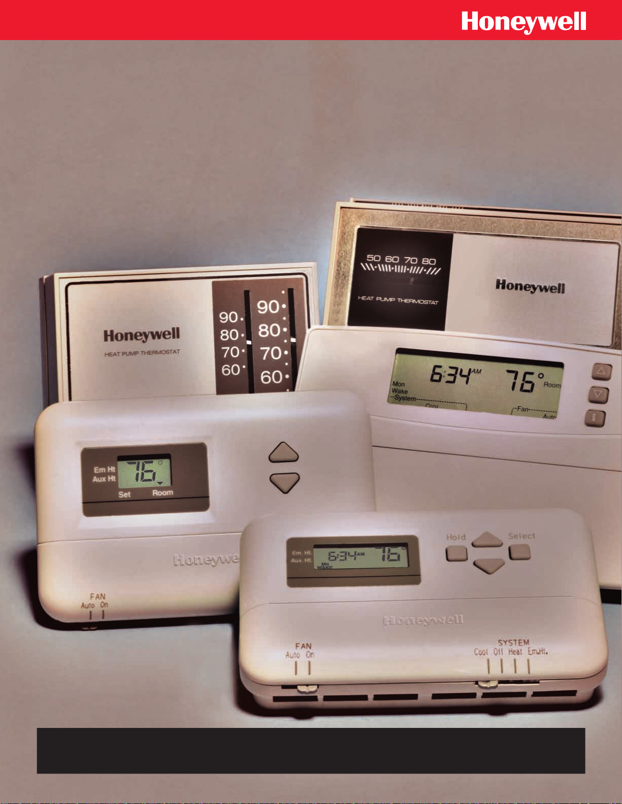
Heat Pump
Thermostat
&
Cross Reference Selection Guide
Page 2
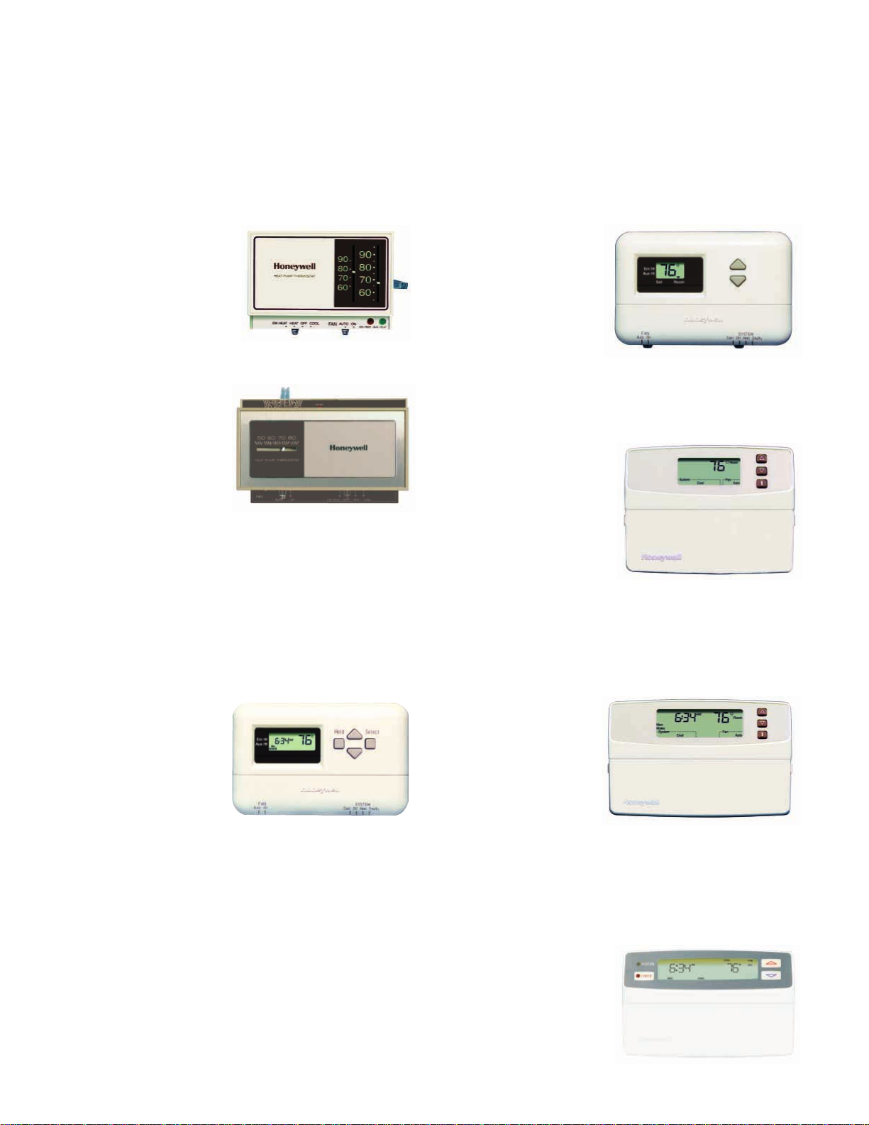
Select a Honeywell Heat Pump Thermostat
for Peak Performance that Meets Every Heat Pump Demand
Rapid advances in heat pump technology, resulting in high efficiency units and lower operating costs, have made the heat pump a popular choice
with consumers. Honeywell heat pump thermostats are ideal for all your heat pump applications and provide the highest level of comfort
available. Our thermostats offer consistent control. They optimize desired comfort level and energy savings. Because your customers’ needs vary,
we’ve developed the most complete line of heat pump thermostats.
NON-PROGRAMMABLE HEAT PUMP THERMOSTATS
T841 Standard Non-Programmable Thermostat
• Good performance without any
“frills”.
• Electromechanical.
• Two heat/one cool; manual
changeover.
• Single-piece construction–no
subbase required.
• Front test probe access for easy
checkout.
Y594 Deluxe Non-Programmable Thermostat
• Proven reliability with excellent
temperature control.
• Electromechanical.
• Classic styling.
• Two heat/one cool; automatic or
manual changeover.
• Two-piece, front-wired construction for easy installation.
T8411 Standard Electronic Non-Programmable
Thermostat
• Microelectronic technology
provides precise zero-droop
performance.
• Attractive styling complements
any décor.
• Two heat/one cool; manual
changeover eliminates
unexpected system operation.
• Large digital display for quick,
easy readability.
• Fan and system switches are located on the lower edge of the
thermostat to eliminate accidental setting changes.
T8511 Deluxe Electronic Non-Programmable
Thermostat
• Microelectronic technology
provides precise zero-droop
performance.
• Attractive styling complements
any décor.
• Two heat/one cool; automatic or
manual changeover.
• Easy-to-read backlit display.
• Most frequently used keys are
located by LCD for quick and easy access to information.
• Outdoor temperature display available with optional outdoor
temperature sensor.
PROGRAMMABLE HEAT PUMP THERMOSTATS
T8011 Standard Programmable Thermostat
• Microelectronic technology
provides precise zero-droop
performance.
• Attractive styling complements
any décor.
• Two heat/one cool; manual
changeover.
• Program up to four time periods
and temperature setpoints.
• Large temperature display for
quick, easy readability.
• Conveniently sized thermostat with two-piece installation make it easy
to install and troubleshoot.
PC8900/W8900B1002 Perfect Climate Comfort Center™ Control System
• Automated, all-in-one comfort control.
• PC8900 Control Panel mounts in living space and accurately measures and
controls room temperature and humidity. W8900 Remote Panel mounts near
the heating and cooling equipment.
• Optional remote sensors can be used for optimum temperature control.
• Up to three heat/two cool.
• Seven-day (auto copy) programming.
• Large, continuously lit display.
• Simultaneous display of heat and cool setpoints with push of a button.
• Circulation fan setting improves indoor air quality.
T8611 Chronotherm® IV Deluxe Programmable
Thermostat
• Microelectronic technology
provides precise zero-droop
performance.
• Attractive styling complements
any décor.
• Two heat/one cool; automatic
or manual changeover.
• Seven-day programming.
• COPY key makes programming easier for the installer and the homeowner.
• Easy-to-read backlit display.
• Adaptive Intelligent Recovery™ optimizes heat pump energy savings.
• Outdoor temperature display available with optional outdoor
temperature sensor.
Page 3

HEAT PUMP THERMOSTAT CROSS REFERENCE/SELECTION GUIDE
Table of Contents
About This Cross Reference/Selection Guide
Heat Pump Thermostat Model Specifications
Thermostat Descriptions and General Information
Understanding Circuits
Typical System Hookup Diagrams
Electronic Thermostat (T8011, T8411, T8511, T8611) Sequences of Operation
Thermostat Manufacturer Cross Reference
Tips for Using This Heat Pump Cross Reference
Wiring Connections for Honeywell Heat Pump Thermostats
Manufacturer Cross Reference
Index
.......................................................................................................................................................................................
Index to Figure Diagrams
............................................................................................................................................................
..........................................................................................................................................
...............................................................................................................................................
........................................................................................................................................................
........................................................................................................................
.........................................................................................................................
.................................................................................................................
...................................................................
............................................................................................................................
...................................................................................................................
..................................................................................................
About This Cross Reference/Selection Guide
1
2-4
5-12
13-14
15-25
26-28
29-32
33
34-35
36-116
117-118
119
Heat pumps require thermostats with special features. This Cross Reference/Selection Guide contains information about
all aspects of selecting a Honeywell replacement thermostat for any heat pump application. Table 1 shows a list of the
Honeywell TRADELINE® and SUPER TRADELINE® OS numbers and their specifications. Immediately following the
table are more detailed descriptions and related application information. In this section you will find additional
information explaining features and requirements that are unique to heat pump thermostat applications. Following the
general information section are the internal schematics, wiring diagrams, and sequence of operation information for the
electronic thermostats. The Thermostat Manufacturer Cross Reference is listed next. Finally, there is the heat pump
manufacturer cross reference, including tips on how to use it. This cross reference, which is organized alphabetically by
equipment or thermostat manufacturer, provides the needed information to select and wire any Honeywell heat pump
thermostat in new installations and replacement applications.
70-6627 • 1
Page 4

HEAT PUMP THERMOSTAT CROSS REFERENCE/SELECTION GUIDE
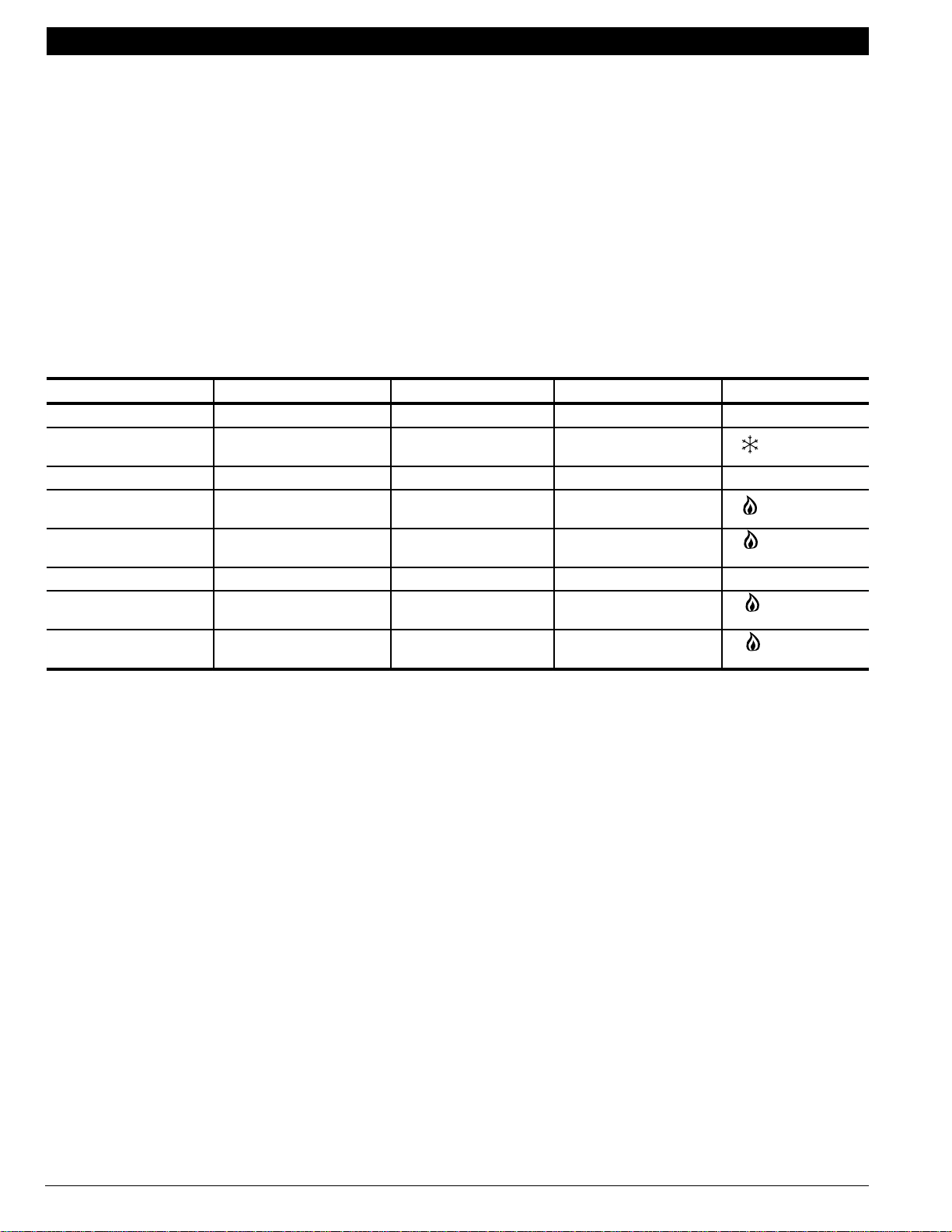
Heat Pump Thermostat Model Specifications
Table 1. Model Number Specifications.
Order
Number
T841A1308 TRADELINE®; fixed anticipation. For
use where E and W2 may be jumpered.
No auto fan in EM.HT. (Fig. 16).
T841A1555 Replaces T841A1068 and T841A1407,
T841A1530, GE AY28Y078 and
AY28Y139. Includes outdoor reset and
fixed anticipation on stage 2 heat. Auto
fan in EM. HT. (Fig. 17).
T841A1712 SUPER TRADELINE®; for two-stage
heating and one-stage cooling. Fixed
anticipation except Stage 2, which is
adjustable. Auto fan in EM. HT. (Fig. 18).
T841A1738 Same as T841A1712, except Premier
White™. SUPER TRADELINE®; for
two-stage heating and one-stage
cooling. Fixed anticipation except
Stage 2, which is adjustable. Auto fan
in EM. HT. (Fig. 18).
T841B1000 For “No Emergency Heat” applications.
Fixed anticipation except stage 2, which
is adjustable. (Fig. 19).
Y594G1161 Includes T874G1204/Q674J1043. With
outdoor reset; replaces GE AY28X077
and AY28X138; no stage 2 heat
anticipation. No auto fan in EM. HT.
(Fig. 20).
Y594G1419 SUPER TRADELINE®; includes
T874G1642/Q674F1444. Auto fan in
EM. HT. (Fig. 22).
Y594G1476 Same as Y594G1419, except Premier
White™; SUPER TRADELINE®.
Includes T874G1741/Q674F1477. Auto
fan in EM. HT. (Fig. 22).
Y594G1633 TRADELINE®; includes T874G1972/
Q674F1584. No auto fan in EM.HT.
Replaces Coleman/Evcon Y594G1377
(Fig. 21).
Y594R1425 SUPER TRADELINE®; includes
T874R1616/Q674L1587. Fixed
anticipation. Auto fan in EM. HT.
(Fig. 25).
Description Terminals Heat Cool
W2,Y,G,R,
O,B,L,E,X
W,Y,G,R,O,
B,X2,T,F,U
W2,W3,Y,G,
B,O,R,X,E
W2,W3,Y,G,
B,O,R,X,E
W1,W2,Y1,
G,R,O,B,X
W,Y,G,R,O,
X2,T,F,B
W1,W2,W3,
Y1,G,R,O,B,
E,X,X1,X2
W1,W2,W3,
Y1,G,R,O,B,
E,X,X1,X2
W2,Y,G,R,
O,B,E,X,L
W1,W2,W3,
G,Y,R,O,B,
E,X,X2,L
Stages
2 1 EM.HT.-
2 1 EM.HT.-
2 1 EM.HT.-
2 1 EM.HT.-
2 1 HEAT-OFF-
2 1 EM.HT.-
2 1 OFF-
2 1 OFF-
2 1 OFF-
2 1 EM. HT.-
Systems Led
Switch
HEAT-OFF-
COOL
HEAT-OFF-
COOL
HEAT-OFF-
COOL
HEAT-OFF-
COOL
COOL
AUTO-OFF
EM.HT.
HEAT-
AUTO-
COOL
EM.HT.
HEAT-
AUTO-
COOL
EM.HT.
HEAT-
AUTO-
COOL
HEAT-OFF-
COOL
Changeover
Manual heat
or cool
Manual cool EM.HT.,
Manual heat
or cool
Manual heat
or cool
Manual heat
or cool
Auto cool AUX.HT.,
Auto heat
or cool
Auto heat
or cool
Auto heat
or cool
Manual heat
or cool
Indication
EM.HT.d,
AUX.HT.
AUX. HT.
EM.HT.,
AUX. HT.
EM.HT.,
AUX. HT.
None
EM.HT.
EM.HT.,
AUX.HT.
CHECK
EM.HT.,
AUX.HT.
CHECK
EM.HT.,
AUX.HT.
AUX. HT.,
EM. HT.,
CHECK
(continued)
c
c
c
70-6627 • 2
Page 5

HEAT PUMP THERMOSTAT CROSS REFERENCE/SELECTION GUIDE
Table 1. Model Number Specifications (continued).
Order
Number
Y594R1763 TRADELINE®; includes
T874R1954/Q674L1827. Replaces
Y594R1136. Auto fan in EM.HT.
(Fig. 23).
Y594R1797 Includes T874R1988/Q674L1868.
Replaces Coleman/Evcon Y594R1235.
No auto fan in EM.HT. (Fig. 24).
T8611G1004 TRADELINE®; 5-1-1 programming.
Auto fan in EM.HT. (Fig. 26).
T8611G1103 Same as T8611G1004, except Premier
White™; TRADELINE®. 5-1-1
programming. Auto fan in EM.HT.
(Fig. 26).
T8611M7008 TRADELINE®; 7 day programming.
Auto fan in EM.HT. (Fig. 27).
T8611R1000 TRADELINE®; 5-1-1 programming.
Auto fan in EM.HT. (Fig. 28).
T8411R1002 TRADELINE®; non-programmable
electronic thermostat. Auto fan in
EM.HT. (Fig. 29).
T8411R1028 Same as T8411R1002 except Premier
White™. Auto fan in EM.HT. (Fig. 29).
T8511G1021 TRADELINE®; Deluxe Electronic
Thermostat. Outdoor sensor capability.
Auto fan in EM.HT. (Fig. 30).
T8511G1047 Same as T8511G1021 except Premier
White™. Outdoor sensor capability.
Auto fan in EM.HT. (Fig. 30).
T8511M1002 TRADELINE®; Deluxe Electronic
Thermostat. Outdoor sensor capability.
Auto fan in EM.HT.
T8011R1006 Same as T8011R1014 except Premier
White™. Fixed anticipation except stage
2, which is selectable. (Fig. 29).
T8011R1014 TRADELINE®; program up to four time
periods and temperatures. Fixed
anticipation except stage 2, which is
selectable. (Fig. 29).
Description Terminals Heat Cool
W,Y,G,R,O,
B,X2,T,F,U
W2,Y,G,R,
O,B,X,E,L
W2,Y,G,R,
C,O,B,E,X1,
X2,L
W2,Y,G,R,
C,O,B,E,X1,
X2,L
W2,W3,Y,Y2,
G,R,C,O,B,
E,X1,X2,L
W1,W2,Y1,
G,R,C,O,B,
E,L,P
W1,W2,Y,
G,R,C,L,
E,O,B
W1,W2,Y,
G,R,C,L,
E,O,B
R,C,Y1,W1,
W2,O/B,G,
E,L,OT,OT
R,C,Y1,W1,
W2,O/B,G,
E,L,OT,OT
R,C,Y1,Y2,
W2,W3,O/B,
G,E,L,OT,OT
R,C,G,W1,
W2,Y,O,
B,E,L
R,C,G,W1,
W2,Y,O,
B,E,L
Stages
Systems Led
Switch
2 1 EM.HT.-
HEAT-OFF-
COOL
AUX.HT.
2 1 EM.HT.-
HEAT-OFF-
COOL
2 1 EM.HT.-
HEAT-OFF-
AUTO-
COOL
2 1 EM.HT.-
HEAT-OFF-
AUTO-
COOL
3 2 EM.HT.-
HEAT-OFF-
AUTO-
COOL
2 1 EM.HT.-
HEAT-OFF-
COOL
2 1 EM.-HT.-
HEAT-OFF-
COOL
2 1 EM.-HT.-
HEAT-OFF-
COOL
2 1 EM.-HT.-
HEAT-OFF-
AUTO-
COOL
2 1 EM.-HT.-
HEAT-OFF-
AUTO-
COOL
3 2 EM.-HT.-
HEAT-OFF-
AUTO-
COOL
2 1 EM.-HT.-
HEAT-OFF-
COOL
2 1 EM.-HT.-
HEAT-OFF-
COOL
Changeover
Indication
Manual cool EM.HT.,
AUX.HT.
Manual cool EM.HT.,
AUX.HT.
Automatic
a
EM.HT.,
AUX. HT.,
CHECK
SYSTEM
Automatic
a
EM.HT.,
AUX.HT.,
CHECK
SYSTEM
Automatic
a
EM.HT.,
AUX.HT.,
CHECK
SYSTEM
Manual EM.HT.d,
AUX.HT.
SYSTEM
Manual None
Manual None
Automatic
Automatic
Automatic
a
a
a
CHECKc
CHECKc
CHECKc
Manual None
Manual None
(continued)
c
b
c
b
c
b
b
70-6627 • 3
Page 6
HEAT PUMP THERMOSTAT CROSS REFERENCE/SELECTION GUIDE
Table 1. Model Number Specifications (continued).
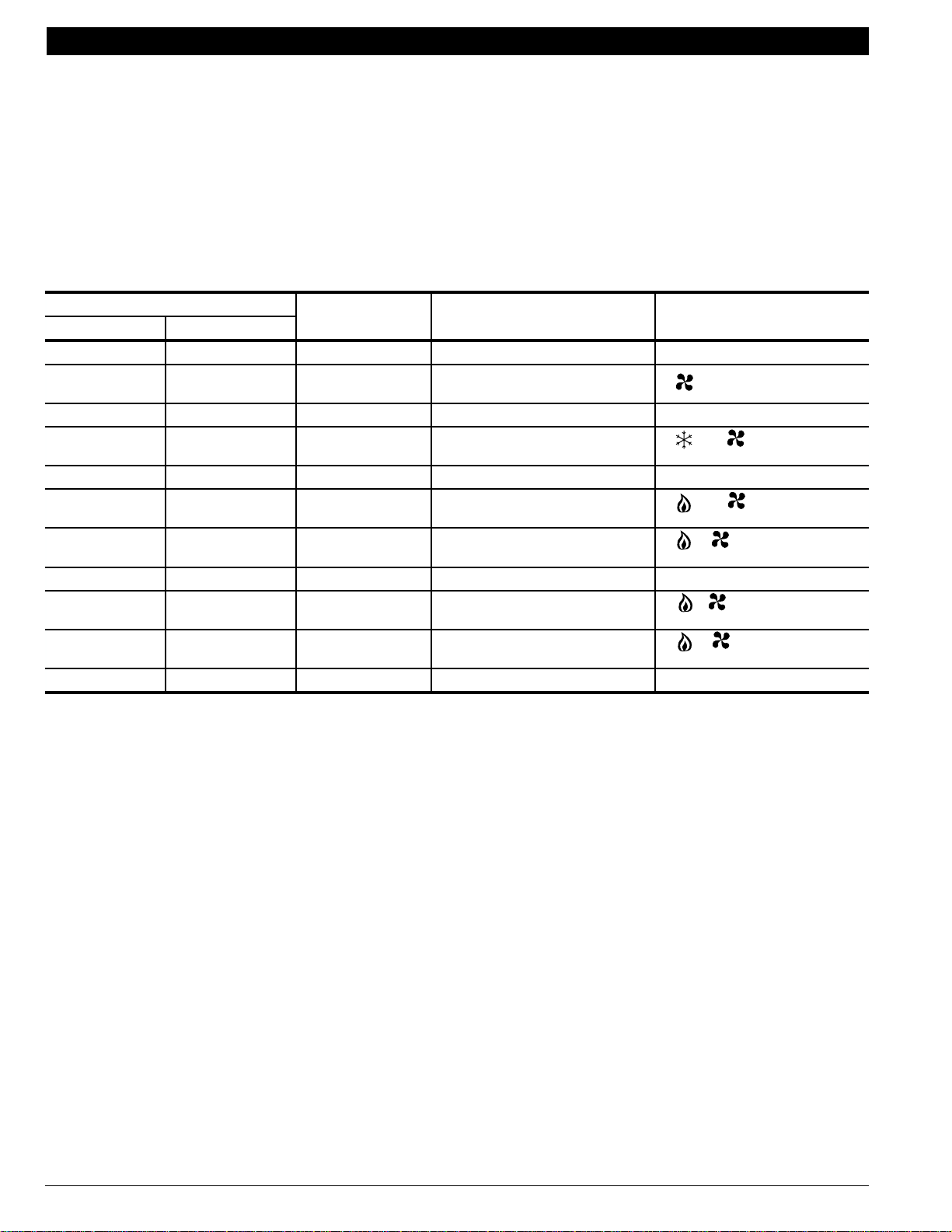
Order
Number
T8611G2002 TRADELINE®; Full seven-day program
capability. Programmable fan and back
lighting features. (Fig. 31).
Description Terminals Heat Cool
Y1,W1,W2,
G,E,L,R,C,
O/B,X1,X2,
OT,OT
T8611G2028 Same as T8611G2002 except Premier
White™, 7-day program capability.
Programmable fan and back lighting
features. (Fig. 31).
T8611M2017 TRADELINE®; full 7-day program
capability. Programmable fan and back
lighting features.
Y1,W1,W2,
G,E,L,R,C,
O/B,X1,X2,
OT,OT
Y1,Y2/W2,
W3,G,E,L,
R,O/B,C,X1,
X2,OT,OT
T8611M2025 Same as T8611M2017 except Premier
White™, 7-day program capability.
Programmable fan and back lighting
features.
PC8900A1007/
W8900B1002
TRADELINE®; Perfect Climate Comfort
Center™ Control System. 7-day (auto
copy) programming.
Y1,Y2,W2,
W3,G,E,L,R,
O/B,C,X1,
X2,OT,OT
R,C,RH,Y1/
W1,G,O/B,
AUX,E,Y2,
W2,L
a
I
n freezing climates, be sure the cooling compressor has adequate cold start protection.
b
SYSTEM LED lights when heating or cooling equipment is running.
c
CHECK LED indicates compressor malfunction.
d
EM. HT. LED indicates compressor malfunction.
e
CHECK LED comes on when 24 Vac is applies to the L terminal.
f
FAIL LED come on when a complete cirucuit is made on the X1 and X2 terminals.
g
CHECK LED lights to alert homeowner to HVAC maintenance or service needs.
Stages
Systems Led
Switch
2 1 EM.HT.-
HEAT-OFF-
AUTO-
COOL
2 1 EM.HT.-
HEAT-OFF-
AUTO-
COOL
3 2 EM.HT.-
HEAT-OFF-
AUTO-
COOL
3 2 EM.HT.-
HEAT-OFF-
AUTO-
COOL
3 2 EM.HT.-
HEAT-OFF-
AUTO-
COOL
Changeover
Automatic
Automatic
Automatic
Automatic
Automatic
a
a
a
a
a
Indication
CHECK
f
FAIL
CHECK
f
FAIL
CHECK
f
FAIL
CHECK
f
FAIL
CHECK
SYSTEM
e
e
e
e
g
b
70-6627 • 4
Page 7

HEAT PUMP THERMOSTAT CROSS REFERENCE/SELECTION GUIDE
Thermostat Descriptions and General Information
This section describes some of the heat pump thermostats that Honeywell manufactures. Since heat pumps require
thermostats with special features such as control of changeover valves, this section also explains some of the features
and requirements unique to heat pump thermostat applications.
Electromechanical Heat Pump Thermostats
T841 Heat Pump Thermostats
The T841 models control two-stage heat and one-stage cool in heat pump systems, using manual changeover. Heat
anticipators are either adjustable or fixed; cooling anticipator is fixed. T841A models include up to three LED indicator
lights; T841B models include up to two LED indicator lights. Provision for an outdoor reset to improve thermal
performance is also available on select models.
Y594 Combination Packs for Heat Pump Applications
The Y594 Packs combine the appropriate T874 Multistage Thermostat and the Q674 Subbase for specific heat pump
applications. Y594G models have automatic changeover; Y594R model has manual changeover. Heat anticipators are
either adjustable or fixed; cooling anticipator is fixed. Accessories include tamper-resistant cover and locking lever
assembly with thermometer, locking lever stops, outdoor thermistor, TG504 Key Lock® Cover, and the TG511
Versaguard™ Universal Thermostat Guard.
Outdoor Reset
Some heat pump thermostats apply outdoor reset to minimize the effect of the interstage differential. It takes more than a
one-degree change in temperature to initiate the second stage of heating. Added to a certain amount of droop under
high loads, there can be a fairly large offset between the setpoint temperature and the room temperature. To correct this
difference, an outdoor thermistor is used.
In warm weather, the outdoor thermistor has a very low resistance, permitting a large amount of current to flow in the
heater. This reduces the call for second stage heating.
In cool weather, the outdoor thermistor has a very high resistance, permitting a small amount of current to flow in the
heater. When this happens, calls for second stage heating are more frequent. This helps reduce the difference between
the setpoint temperature and the room temperature.
Select one of the following T841 or Y594 models if a thermostat with outdoor reset capability is required:
T841A1555
Y594G1161
Y594R1763
If an outdoor thermistor is not provided, use the Honeywell C815A Outdoor Thermistor, ordered separately.
NOTE: All Honeywell
electronic
heat pump thermostats are droopless controls and do not require the use of outdoor reset.
Electronic Non-programmable Heat Pump Thermostats
T8411 Electronic Heat Pump Thermostats
The T8411 models control two-stage heat and one-stage cool in heat pump systems, using manual changeover only.
First stage heat anticipation is fixed; second stage heat anticipation is selectable at 3, 6, or 9 cph. Setpoints are
permanently held in memory (no batteries required) and retained during power failures. Electronic thermostats provide
droopless temperature control.
70-6627 • 5
Page 8

HEAT PUMP THERMOSTAT CROSS REFERENCE/SELECTION GUIDE
T8511 Deluxe Electronic Heat Pump Thermostats
The T8511 models control two-stage heat and one-stage cool in heat pump systems, using manual or automatic
changeover. First stage heat anticipation is fixed; second stage heat anticipation is selectable at 3, 6, or 9 cph. Setpoints
are permanently held in memory (no batteries required) and retained during power failures. Electronic thermostats provide
droopless temperature control. The T8511 models also include a backlit display and outdoor sensing capability.
Electronic Programmable Heat Pump Thermostats
T8011 Standard Electronic Heat Pump Thermostats
The T8011 models provide two-stage heat and one-stage cool control for heat pump systems, using manual
changeover. First stage heat anticipation is fixed; second stage heat anticipation is selectable at 1, 3, 6, or 9 cph. The
user can program up to four time periods and temperature setpoints. All programs and setpoints are permanently held in
memory in the event of a power outage. Electronic thermostats provide droopless temperature control.
Chronotherm® III Electronic Heat Pump Thermostats
The T8611 Chronotherm III models provide up to three-stage heat and two-stage cool control for heat pump systems,
using manual or automatic changeover. Models are available with selectable daily schedules for weekdays, Saturday,
and Sunday; or full 7-day programming. Models include LED indication for system operation and status. Battery backup,
with low battery indication, maintains clock and memory during power outages. Adjustable second stage cycling allows
for use of the thermostat with electric heat or fossil fuel while providing optimum comfort.
Using the Chronotherm III or Chronotherm IV T8611M on Two-Speed Heat Pump Compressor Equipment
The T8611M is a three-stage heat/two-stage cool thermostat used to control multistage heat pump equipment. However,
there is no difference in controlling multistage equipment and in controlling two-speed multistage equipment. The
differential required between stage 1 and stage 2 in multistage equipment is the same as the differential required
between low-speed and high-speed in two-speed equipment.
To connect the T8611M to two-speed heat pump equipment:
1. Connect the Y terminal to the low-speed compressor terminal.
2. Jumper the Y2 and W2 terminals.
3. Connect the Y2 terminal to the high-speed compressor terminal.
4. Connect all other terminals as shown in the wiring diagram below.
5. Configure the O/B terminal for changeover in either heating or cooling.
Equipment Function
Transformer Common
Power
Cooling Changeover
Heating Changeover
1st Stage Compressor
2nd Stage Compressor
Fan
a
a
Equipment
Terminals
C C
RR
GG
OO or
BB or
YY
Y2 Y2
T8611M
Terminals
O/B
O/B
a
W2
70-6627 • 6
Third Stage Heat
Emergency Heating
Fig. 1. Using the T8611M on two-speed heat pump compressor equipment.
a
On selected T8611M models, the high speed compressor is wired to the Y2 terminal. In these cases, no jumper is required.
W3 W3
EE
M13229
Page 9

HEAT PUMP THERMOSTAT CROSS REFERENCE/SELECTION GUIDE
Chronotherm IV Electronic Deluxe Heat Pump Thermostats
The T8611 Chronotherm IV thermostat models provide up to three-stage heat and two-stage cool control for heat pump
systems, using manual or automatic changeover. These models provide full 7-day programming capability. Models with
programmable fan operation are available for homeowner comfort. Backlighting on the large display makes the LCD very
easy to read. Adaptive Intelligent Recovery™ control brings the room temperature to the desired temperature setpoint at the
programmed time, maximizing comfort and energy savings. First stage heat anticipation is fixed; second stage heat
anticipation is selectable.
Adaptive Intelligent Recovery™ Control (Night Setback and Heat Pumps)
Heat pump applications are ideal for night setback and energy savings. However, in order to maximize the energy saved
in a night setback mode, use the T8611 Chronotherm® III or T8611 Chronotherm® IV Thermostats with Adaptive
Intelligent Recovery™ control.
Adaptive Intelligent Recovery™ control assures that the comfort setting is achieved at the programmed time regardless
of weather conditions. Conventional recovery starts recovery at the beginning of the programmed time period and uses
the equipment to achieve the comfort settings as soon as possible.
Unlike the Chronotherm
mode in the Chronotherm IV thermostat. Honeywell does not recommend this because the auxiliary heat comes on
when the program time begins, and runs continuously until the setpoint is reached.
III models, the Adaptive Intelligent Recovery control can be turned off in the Installer Set-up
Applications Requiring Special System Hookups
Using a Chronotherm III T8611G or T8611M on Systems Requiring Separate W1 and Y
Terminals
The Chronotherm III T8611G and T8611M are designed with only one common compressor terminal. The Y terminal is
energized on a call for stage 1 heat and stage 1 cool. However, some multistage heat pump equipment requires one
terminal to be energized on a call for stage 1 heat (W
In order for the T8611G or T8611M to accommodate this requirement, a separate switching relay must be added to the
installation. See the following wiring diagrams for heat pumps that provide changeover in the heating mode and for heat
pumps that provide changeover in the cooling model.
Heat Pumps with Heating Mode Changeover
Here is how the switching relay allows the system to work properly:
* The Y terminal is connected to the equipment terminal W1 through the normally closed contacts on the R8222B
Switching Relay. When the thermostat calls for heat, the thermostat Y terminal activates the first stage of heating.
* The O terminal is connected to the coil terminals on the R8222B Switching Relay. When the system switch is in the
COOL position, the O terminal is energized, reversing the logic of the Chronotherm III T8611G and T8611M Y
terminal. Now when the thermostat calls for cooling, the Y terminal activates the first stage of cooling.
) and one terminal to be energized on a call for stage 1 cool (Y1).
1
1
70-6627 • 7
Page 10
HEAT PUMP THERMOSTAT CROSS REFERENCE/SELECTION GUIDE
Fan
Equipment
Terminals
RR
Y1
Y2 Y2
GG
W1
W2 W2
CC
BB
Equipment Function
Power
1st Stage Cool
2nd Stage Cool
1st Stage Heat
2nd Stage Heat
Transformer Common
Heating Changeover
Fig. 2. Installing an R8222B Switching Relay on heat pumps requiring heating mode changeover.
Heat Pumps with Cooling Mode Changeover
Here is how the switching relay allows the system to work properly:
* The Y terminal is connected to the equipment terminal Y1 through the normally closed contacts on the R8222B
Switching Relay. When the thermostat calls for cooling, the thermostat Y terminal activates the first stage of cooling.
T8611M
Terminals
Y
O
R8222B Relay
M13231
* The B terminal is connected to the coil terminals of the R8222B Switching Relay. When the system switch is in the
HEAT position, the B terminal is energized, reversing the logic of the Chronotherm® III T8611G and T8611M Y
terminal. Now when the thermostat calls for heating, the Y terminal activates the first stage of heating.
Equipment Function
Power
1st Stage Cool
2nd Stage Cool
Fan
1st Stage Heat
2nd Stage Heat
Transformer Common
Cooling Changeover
Equipment
Terminals
RR
Y1
Y2 Y2
GG
W1
W2 W2
CC
OO
R8222B Relay
T8611M
Terminals
Y
B
M13230
70-6627 • 8
Fig. 3. Installing an R8222B Switching Relay on heat pumps requiring cooling mode changeover.
Page 11
HEAT PUMP THERMOSTAT CROSS REFERENCE/SELECTION GUIDE
Changing Fan Operation in Emergency Heat Mode for Electronic Thermostats
In the emergency heat mode (system switch in EM. HT. position), the thermostat controls the fan operation with a call for
first stage heat. This means that when the thermostat calls for heat, the thermostat also calls for fan operation. However,
this fan operation is not desirable on some types of systems.
To change the fan operation on the TRADELINE and SUPER TRADELINE models, follow the wiring diagram shown
below. Connecting the thermostat and relay to the equipment in this manner disables the fan switch in the emergency
heat mode. During normal operation, the fan switch is enabled and the fan operation is as described in the installation
instructions.
R (Power)
E C (Common)
E (EM. Heat)
G G (Fan)
Thermostat
Fig. 4 Changing fan operation in emergency heat mode for electronic thermostats.
R8222B Relay
Equipment
M13232
Heat Pump Manufacturer Relay Wiring Connections
The wiring connections for some thermostats to specific types of heat pump equipment require a separate relay for
proper operation. Refer to Fig. 5 through 13 for the wiring connections of these types of equipment.
Equipment Function
Transformer Common
1st Stage Cooling
1st Stage Heating
Existing Control
Terminal Designation
CC
Y1
W1
New T erminal
Designation
Y
O
M13235
Fig. 5. Relay wiring connections for Carrier equipment (typical 38BQ), and T8511M, T8611M,
PC8900/W8900B1002. Require relay (R8222B1067 typically) for proper operation.
70-6627 • 9
Page 12
HEAT PUMP THERMOSTAT CROSS REFERENCE/SELECTION GUIDE
Equipment Function
Common
Power
Existing Control
Terminal Designation
Black
Red
New T erminal
Designation
C
R
Emergency Heat
AL
E
M13241
Fig. 6. Relay wiring connections for Evcon/Coleman equipment (3200, 3300). Requires R8222B1067
Relay to operate system. Equipment requires normally energized emergency heat.
Equipment Function
Common
Existing Control
Terminal Designation
Black
New T erminal
Designation
C or X
Power
Emergency Heat
Red
A
R
E
M13236
Fig. 7. Relay wiring connections for Evcon/Coleman equipment (3200, 3300, 3360, 3400, 6000, and 6500).
Requires R8222B1067 Relay to operate system. Equipment requires normally energized emergency heat.
Equipment Function
Indoor Power
System Monitor
Existing Control
Terminal Designation
VR
L
New T erminal
Designation
R
or
X1
L
M13237
Fig. 8. Relay wiring connections for Lennox equipment (HP9, HP10). Requires R8222B1067 Relay to operate the
system monitor light (emergency heat LED) on TRADELINE replacement thermostats. Tape off if light is not desired.
70-6627 • 10
Page 13
HEAT PUMP THERMOSTAT CROSS REFERENCE/SELECTION GUIDE
Equipment Function
Power
System Monitor
Existing Control
Terminal Designation
VR
L
New T erminal
Designation
R
or
or
X1
L
F
M13238
Fig. 9. Relay wiring connections for Lennox equipment (HP16, HP19, HP21, HP22 Direct Replacements).
Requires R8222B1067 Relay to operate the system monitor light (emergency heat LED) on
TRADELINE replacement thermostats. Tape off if light is not desired.
Equipment Function
Power
System Monitor
Existing Control
Terminal Designation
RR
X1
New T erminal
Designation
or
L
X1
M13239
Fig. 10. Relay wiring connections for Magic Chef equipment (PE Series). Requires R8222B1067 Relay
if outdoor section has reset shunt relay and malfunction light indicator is desired on thermostat.
Equipment Function
Power
System Monitor
Existing Control
Terminal Designation
R1
or R R
L or X
New T erminal
Designation
or
X1
L
M13240
Fig. 11. Relay wiring connections for Mammoth. Requires R8222B1067 Relay if outdoor
section has reset shunt relay and malfunction light indicator is desired on thermostat.
70-6627 • 11
Page 14
HEAT PUMP THERMOSTAT CROSS REFERENCE/SELECTION GUIDE
Equipment Function
Transformer Common
Power
Fan
Equipment
Terminals
CC
RR
GG
PC8900
Terminals
O/B
1st Stage Heating
1st Stage Cooling
Changeover V alv e
2nd Stage Heating
Emergency Heat
2nd Stage Cooling
W1 Y1/W1
Y1
B
W2 Aux.
EE
Y2 Y2
M13233
Fig. 12. Relay wiring connections for PC8900 in heat pump applications
requiring separate Y
Equipment Function
Transformer Common
and W1 terminals with a heating changeover.
1
Equipment
Terminals
PC8900
Terminals
CC
Power
Fan
RR
GG
O/B
1st Stage Cooling
1st Stage Heating
Changeover V alv e
2nd Stage Heating
Emergency Heat
2nd Stage Cooling
Y1 Y1/W1
W1
O
W2 Aux.
EE
Y2 Y2
Fig. 13. Relay wiring connections for PC8900 in heat pump applications
requiring separate Y1 and W1 terminals with a cooling changeover.
M13234
70-6627 • 12
Page 15
HEAT PUMP THERMOSTAT CROSS REFERENCE/SELECTION GUIDE
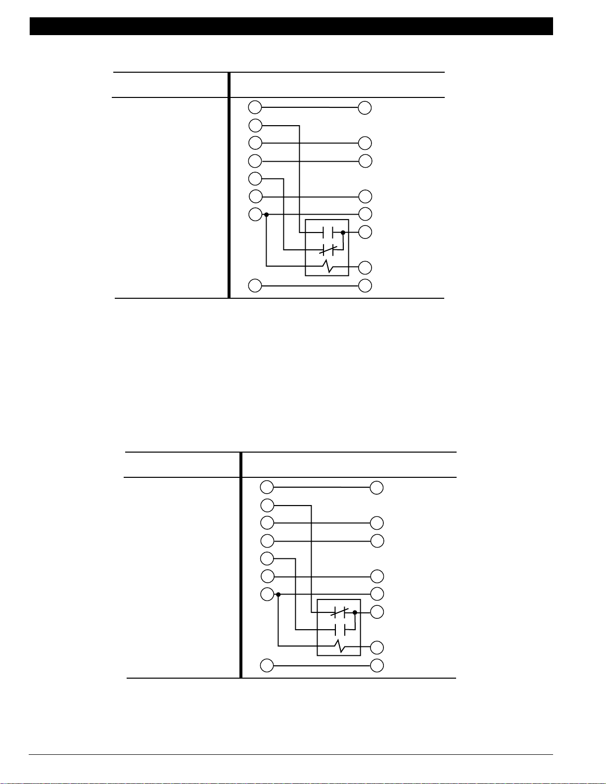
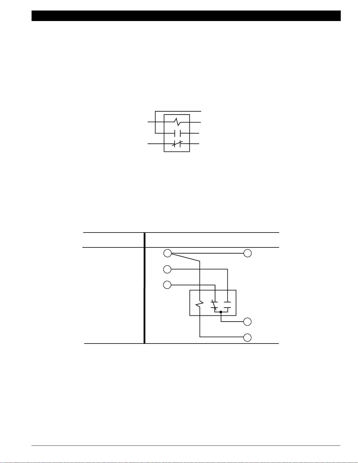
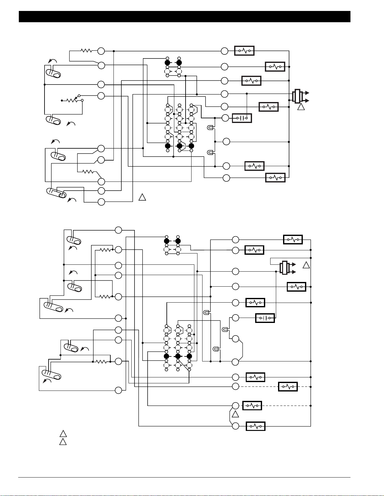
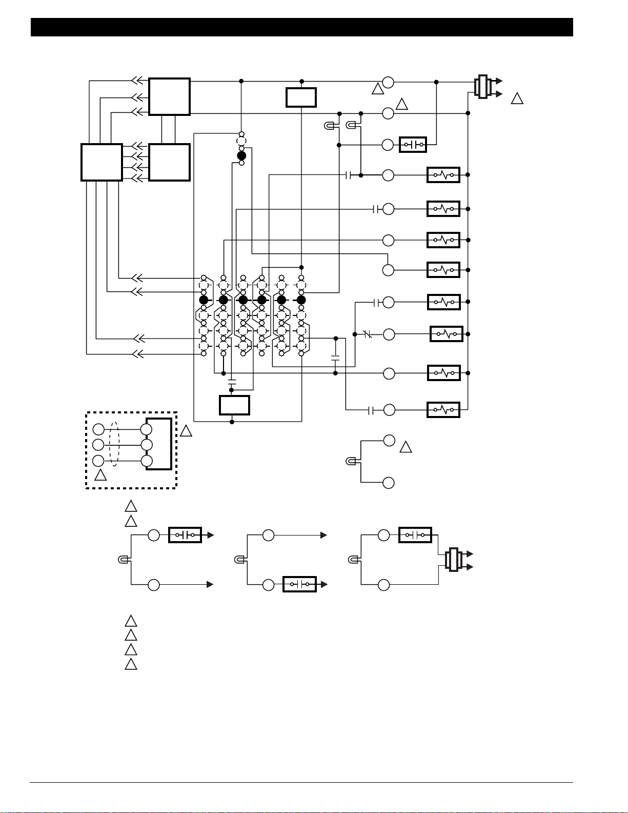
Understanding Circuits
To understand wiring diagrams, it is important to know what all the symbols mean and how to trace the path of the
circuits from the transformer. Circuit descriptions and terminology are defined as follows:
Auto changeover—refers to the presence of an AUTO position in the system switching (EX: Q674F with OFF-COOL
AUTO-HEAT-EM. HEAT switching). The thermostat automatically changes between heat and cool modes as
indoor temperature changes.
Manual changeover—requires a system switch movement to change mode (EX: Q674L with EM. HT.-HEAT-OFF-
COOL switching).
Cool changeover valve—operates on cooling. The reversing valve or relay is activated either by moving the system
switch to COOL (manual changeover) or by a mercury switch that makes on a temperature rise (auto changeover).
Heat changeover valve—operates on heating. The reversing valve or relay is activated either by moving the system
switch to HEAT (manual changeover) or by a mercury switch that makes on a temperature fall (auto changeover).
System monitor relay—optional equipment on some heat pumps. This system monitor relay detects a malfunction in
the compressor and indicates the malfunction by activating the EMERGENCY HEAT LED on the switching
subbase. The system monitor relay may be wired to the L terminal on some thermostats
Each mercury switch is identified by function:
H1—Stage 1 Heating.
H2—Stage 2 Heating.
H3—Stage 3 Heating.
C1—Stage 1 Cooling.
C2—Stage 2 Cooling.
C3—Stage 3 Cooling.
C/O—Changeover (heat pumps).
Each anticipator is identified and each switch affected is named (EX: H1 anticipator, C1 anticipator).
All T874 Multistage Thermostats use mercury switches. Each schematic indicates switch operation by being drawn
in the open position with an arrow indicating operation with a temperature RISE or FALL.
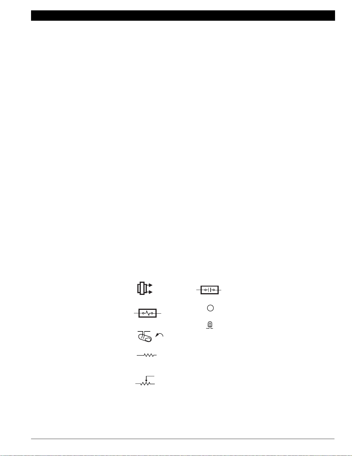
KEY TO HOOKUP SYMBOLS
TRANSFORMER
(24 VAC SECONDARY)
RELAY OR CONTACTOR COIL
MERCURY SWITCH
FIXED ANTICIPATOR
HIGH RESISTANCE
(TYPICALLY 5 KILOHMS)
ADJUSTABLE ANTICIPATOR
LOW RESISTANCE
(TYPICALLY 0 TO 5 OHMS)
RELAY/CONTACTOR CONTACTS
B
TERMINAL
LED
ODT
OUTDOOR THERMOSTAT
EHR
EMERGENCY HEAT RELAY
RTD
TIME DELAY RELAY
RD
DEFROST RELAY
CHP
PRESSURE SWITCH
LACO
LOW AMBIENT CUTOFF
M5848
Fig. 14. Key to hookup symbols.
70-6627 • 13
Page 16

HEAT PUMP THERMOSTAT CROSS REFERENCE/SELECTION GUIDE
NEMA Standard Transformers Give You Better Control
UL sets the safety standards all transformers must meet. But these are minimum standards. The Honeywell AT20A,
AT40A, AT72D and AT87A Transformers do even more; they meet tough voluntary standards of the National Electrical
Manufacturer’s Association (NEMA).
Why is this so important? Because today’s sophisticated control systems require reliable, accurate voltage output for
optimal system performance. It’s especially important for electrical controls (OEM boards in high efficiency furnaces, for
example) or resistive heaters, such as thermostat heat anticipators.
For better performance, some heat pumps require a NEMA standard transformer. Conformance to NEMA standards
assures the voltage output of a transformer will remain within acceptable limits, regardless of load conditions. No
excessively high open-circuit voltage under light load conditions. No low, “brown-out” voltage levels under heavy load
conditions. At 100% load, the transformer secondary must supply between 23 and 25 volts to meet the NEMA standard.
How can you tell that the transformers you buy meet this tough, high standard? Look for the transformer to be marked:
NEMA Type B (20VA), NEMA Type D (40VA), NEMA Type E (48-50 VA). Only transformers conforming to the NEMA
standard can be marked in this way. The following are recommended Honeywell NEMA standard transformers:
AT72D1691, AT72D1683, AT87A1106
27
26
25
24
23
22
21
20
19
18
SECONDARY VOLTAGE
17
16
15
14
0 50 100 150
% OF LOAD
200
M993
Fig. 15. NEMA Class 2 transformer band.
70-6627 • 14
Page 17
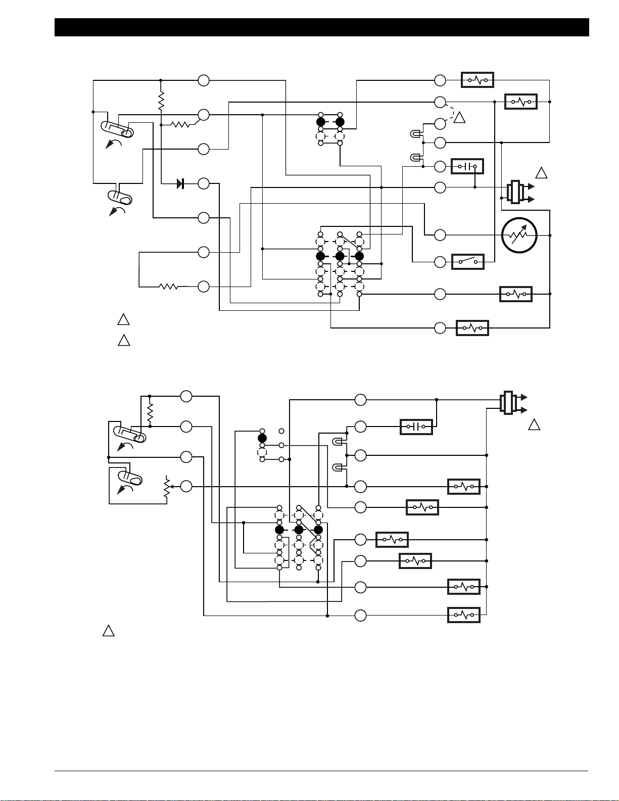
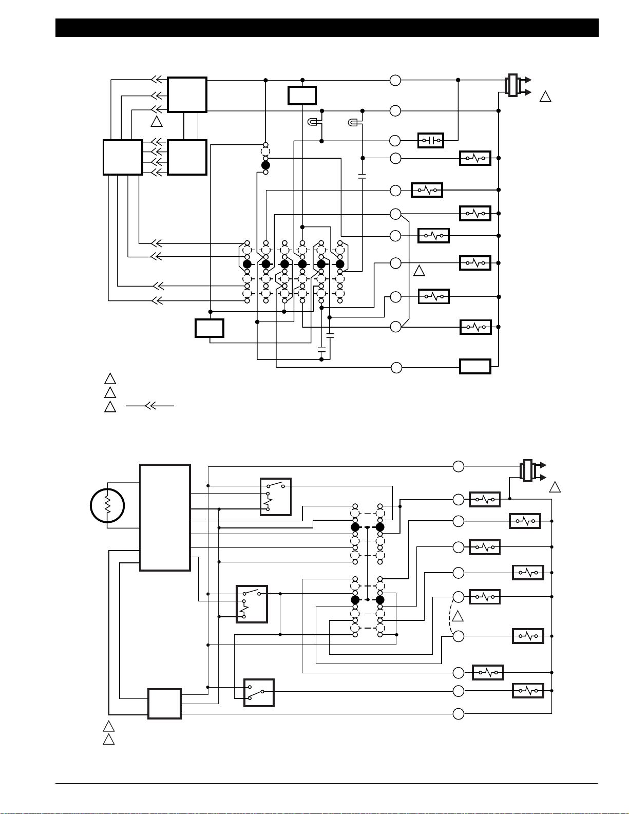
HEAT PUMP THERMOSTAT CROSS REFERENCE/SELECTION GUIDE
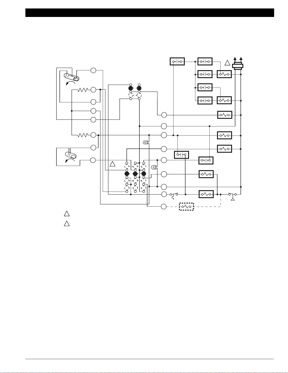
Typical System Hookup Diagrams
L1
(HOT)
L2
2
EM. HT.
HEAT
COOL
SYSTEM
SWITCH
FAN
SWITCH
AUTO
OFF
H1
H2
C1
FALL
H1/C1
ANTICIPATOR
H2 ANTICIPATOR
FALL
1
POWER SUPPLY. PROVIDE DISCONNECT MEANS AND
OVERLOAD PROTECTION AS REQUIRED.
NO AUTO FAN IN EMERGENCY HEAT.
2
ON
G
R
W2
AUX. HT.
LED (GREEN)
E
L
EM. HT.
LED (RED)
B
X
Y
O
RTD 1
LACO CHP
COOL CHANGEOVER VALVE
ODT 1
EHR 1
ODT 2
EHR 2
RD
SYSTEM MONITOR
HEAT CHANGEOVER VALVE
COMPRESSOR
CONTACTOR
1
RTD 2
RTD 3
FAN RELAY
RTD 1
EM. HT. RELAY
M6060A
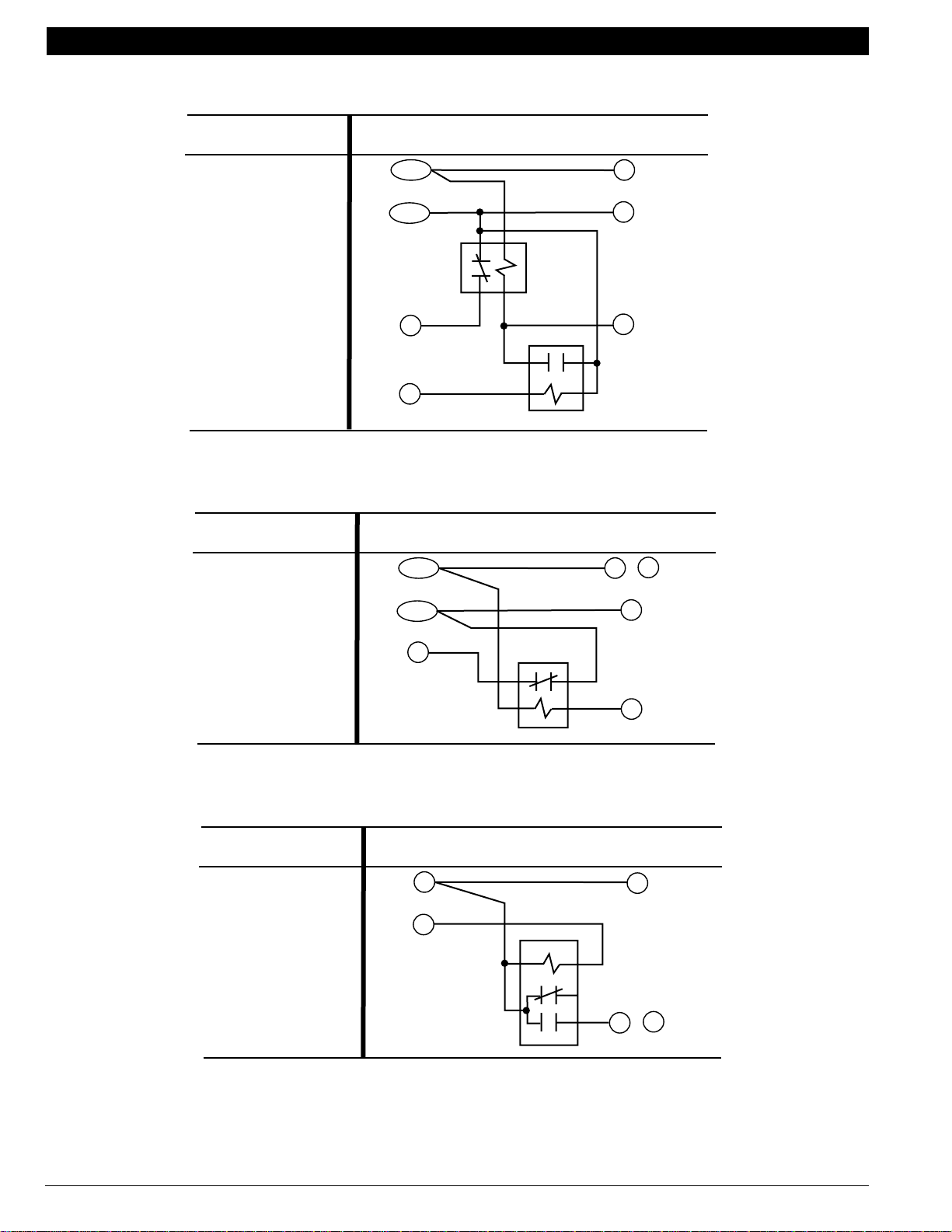
Fig. 16. Internal schematic and typical wiring diagram for T841A1308.
70-6627 • 15
Page 18
HEAT PUMP TH ERMOSTAT CROSS REFERENCE/SELECTION GUIDE
9
H1
C1
FALL
C
ANTICIPATOR
H1/C
ANTICIPATOR
H2
FALL
RESET
1
POWER SUPPLY. PROVIDE DISCONNECT MEANS
AND OVERLOAD PROTECTION AS REQUIRED.
2
FIELD REMOVABLE JUMPER.
AUTO FAN IN EMERGENCY HEAT.
3
2
3
5
8
11
12
10
1
4
Fig. 17. Internal schematic and typical wiring diagram for T841A1555.
FAN
SWITCH
AUTO
ON
SYSTEM SWITCH
3
EM. HT.
HEAT
OFF
COOL
AUX. HEAT
LED (GREEN)
EM. HEAT
LED (RED)
G
FAN RELAY
W
2
U
B
F
COMPRESSOR
MONITOR
R
OUTDOOR
THERMOSTAT
X2
T
O
COOL CHANGEOVER
RELAY
Y
AUX. HEAT
RELAY
OUTDOOR
THERMISTOR
COMPRESSOR
CONTACTOR
M8728
L1
(HOT)
L2
1
FALL
H1
C1
10
5
H1
ANTICIPATOR
C1
ANTICIPATOR
7
8
2
3
9
6
12
H2
ANTICIPATOR
H2
FALL
1
POWER SUPPLY. PROVIDE DISCONNECT MEANS
AND OVERLOAD PROTECTION AS REQUIRED.
11
FAN
SWITCH
AUTO
ON
SYSTEM
SWITCH
EM. HT.
HEAT
OFF
COOL
EM. HEAT
LED (RED)
AUX. HEAT
LED (GRN)
W3
O
G
R
E
X
W2
B
Y
COOL
CHANGEOVER
RELAY
FAN RELAY
EM. HEAT RELAY
HEAT
CHANGEOVER
RELAY
W3 RELAY
AUX. HEAT RELAY
COMPRESSOR
CONTACTOR
M13249
L2
L1
(HOT)
1
70-6627 • 16
Fig. 18. Internal schematic and typical wiring diagram for T841A1712 and T841A1738.
Page 19
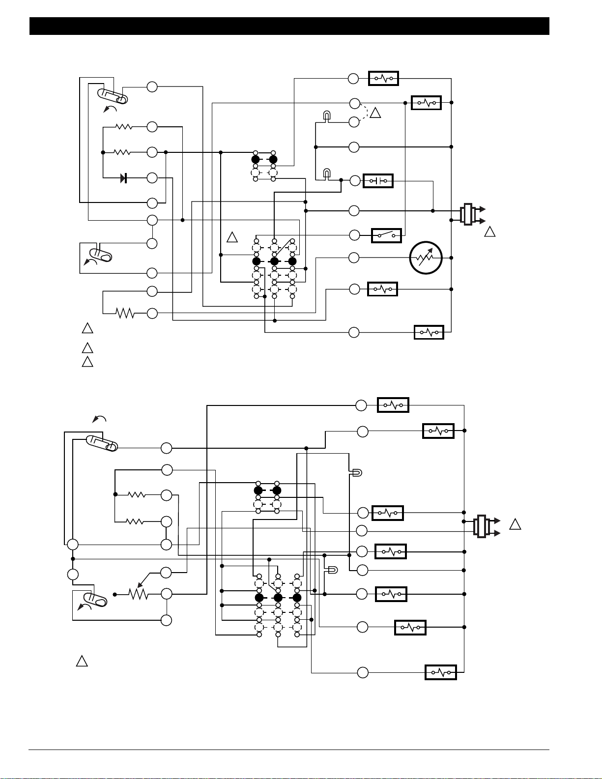
HEAT PUMP THERMOSTAT CROSS REFERENCE/SELECTION GUIDE
H1/C1
ANTICIPATOR
H1
1
C1
FALL
FAN SWITCH
AUTO
ON
SYSTEM
SWITCH
H2 ANTICIPATOR
H2
POWER SUPPLY. PROVIDE DISCONNECT MEANS AND OVERLOAD PROTECTION AS REQUIRED.
FALL
HEAT
OFF
COOL
Fig. 19. Internal schematic and typical wiring diagram for T841B1000.
W1
HEAT RELAY 1
W2
HEAT RELAY 2
B
HEAT CHANGEOVER
VALVE
G
FAN RELAY
R
X
Y1
COMPRESSOR
CONTACTOR
O
COOL CHANGEOVER VALVE
M6068A
L1
(HOT)
L2
1
H2
FALL
CHANGEOVER
FALL
H1
H1 ANTICIPATOR
RISE
C1
RESET
HEATER
C1
ANTICIPATOR
RISE
FAN
SWITCH
AUTO
ON
SYSTEM
SWITCH
EM .HT.
AUTO
OFF
1
POWER SUPPLY. PROVIDE DISCONNECT MEANS AND OVERLOAD PROTECTION AS REQUIRED.
T
G
O
R
X2
W
AUX. HT.
LED (GREEN)
B
EM. HT.
LED (RED)
F
Y
OUTDOOR
THERMOSTAT
CHANGEOVER
VALVE
C815A OUTDOOR
THERMISTOR
FAN RELAY
AUX. HT.
RELAY
L1
(HOT)
L2
M1593
1
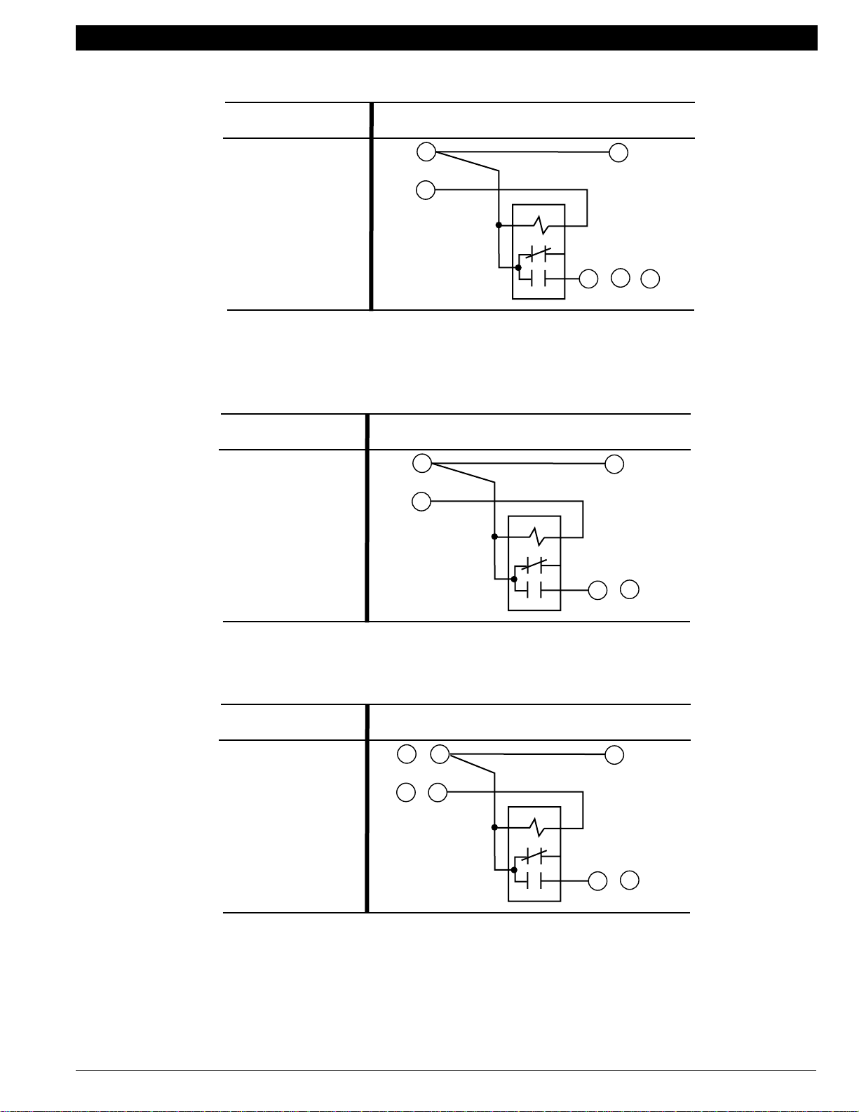
Fig. 20. Internal schematic and typical wiring diagram for Y594G1161.
70-6627 • 17
Page 20
HEAT PUMP THERMOSTAT CROSS REFERENCE/SELECTION GUIDE
FALL
H1
CO
H1
RISE
H1 ANTICIPATOR
H2
ANTICIPATOR
FALL
H2
RISE
C1
C1 ANTICIPATOR
RISE
1
2
4
6
8
9
10
11
12
FAN SWITCH
AUTO
ON
SYSTEM
SWITCH
OFF
EM. HT.
HEAT
AUTO
COOL
POWER SUPPLY. PROVIDE DISCONNECT MEANS AND
1
OVERLOAD PROTECTION AS REQUIRED.
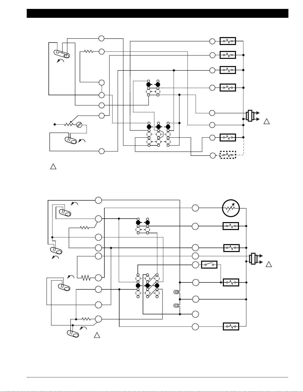
Fig. 21. Internal schematic and typical wiring diagram for Y594G1633.
1
CHANGEOVER
(HEAT)
FALL
FALL
FALL
CHANGEOVER
(COOL)
C1
1
POWER SUPPLY. PROVIDE DISCONNECT MEANS AND OVERLOAD PROTECTION AS REQUIRED.
2
W1 - Y1 JUMPER IS Y TERMINAL; REMOVE JUMPER WHEN W1 RELAY IS USED.
H2
H2 ANTICIPATOR
RISE
C1
ANTICIPATOR
H1
ANTICIPATOR
2
3
4
5
6
8
9
10
11
FAN
SWITCH
AUTO
ON
SYSTEM
SWITCH
OFF
EM. HT.
HEAT
AUTO
COOL
O
G
B
R
E
L
EM. HT.
LED (RED)
X
AUX. HEAT
LED (GREEN)
W2
Y
AUX.
HT. LED
(GREEN)
EM. HT.
LED (RED)
COOL CHANGEOVER
VALVE
B RELAY
EM. HT. RELAY
AUX. HEAT RELAY
W3
G
FAN RELAY
R
W2
EM. HT.
RELAY
E
X1
CHECK
LED (RED)
X2
X
O
B
W1
2
Y1
COMPRESSOR
FAULT
COOL CHANGEOVER
VALVE
W1 RELAY
COMPRESSOR
CONTACTOR
FAN RELAY
COMPRESSOR
CONTACTOR
M8702
W3 RELAY
AUX. HEAT
RELAY
HEAT CHANGEOVER
VALVE
1
L2
L1
(HOT)
1
L1
(HOT)
L2
M8703
70-6627 • 18
Fig. 22. Internal schematic and typical wiring diagram for Y594G1419 and Y594G1476.
Page 21
HEAT PUMP THERMOSTAT CROSS REFERENCE/SELECTION GUIDE
1
2
H1
C1
FALL
H2
FALL
POWER SUPPLY. PROVIDE DISCONNECT MEANS AND
1
OVERLOAD PROTECTION AS REQUIRED.
FIELD REMOVABLE JUMPER.
2
3
4
5
6
11
AUTO
ON
SYSTEM
SWITCH
EM. HEAT
HEAT
OFF
COOL
FAN
SWITCH
AUX. HEAT
LED (GREEN)
EM. HEAT
LED (RED)
G
FAN RELAY
W
2
U
B
COMPRESSOR
MONITOR
F
R
T
X2
OUTDOOR
THERMOSTAT
O
COMPRESSOR
CONTACTOR
Y
AUX. HEATER
RELAY
OUTDOOR
SENSOR
COOL
CHANGEOVER
VALVE
M8701
1
L1
(HOT)
L2
Fig. 23. Internal schematic and typical wiring diagram for Y594R1763.
2
H1 AND C1
ANTICIPATOR
3
H1
POWER SUPPLY. PROVIDE DISCONNECT MEANS AND OVERLOAD PROTECTION AS REQUIRED.
1
FALL
FALL
C1
H2
ANTICIPATOR
H2
4
6
FAN
SWITCH
AUTO
ON
SYSTEM
SWITCH
EM. HT.
HEAT
OFF
COOL
R
L
EM. HEAT
LED (RED)
X
AUX. HEAT
LED (GRN)
W2
G
O
E
Y
B
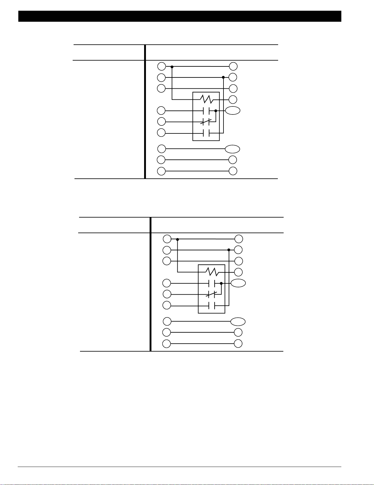
Fig. 24. Internal schematic and typical wiring diagram for Y594R1797.
FAN RELAY
COOL
CHANGEOVER
VALVE
EM. HEAT
RELAY
AUX. HEAT
RELAY
COMPRESSOR
CONTACTOR
"B" RELAY
M8700
L1
(HOT)
L2
1
70-6627 • 19
Page 22
HEAT PUMP THERMOSTAT CROSS REFERENCE/SELECTION GUIDE
H1
H1
ANTICIPATOR
C ANTICIPATOR
C
FALL
H2
ANTICIPATOR
H2
FALL
POWER SUPPLY. PROVIDE DISCONNECT MEANS AND OVERLOAD
1
PROTECTION AS REQUIRED.
2
REMOVE JUMPER WHEN W1 RELAY IS USED.
3
FACTORY-INSTALLED JUMPER.
1
2
3
4
5
6
11
FAN
SWITCH
AUTO
ON
SYSTEM
SWITCH
EM. HT.
HEAT
OFF
COOL
EM. HT.
LED (RED)
AUX. HT.
LED (GRN)
W3
O
L
G
R
W2
AUX. HT. RELAY
E
EM. HT. RELAY
X
3
HEAT
X2
CHANGEOVER
VALVE
B
W1 RELAY
W1
COMPRESSOR
2
CONTACTOR
Y
W3 RELAY
COOL CHANGEOVER
VALVE
COMPRESSOR
MONITOR
FAN RELAY
M8713
L1
(HOT)
L2
1
Fig. 25. Internal schematic and typical wiring diagram for Y594R1425.
70-6627 • 20
Page 23
HEAT PUMP THERMOSTAT CROSS REFERENCE/SELECTION GUIDE
2
L1
(HOT)
L2
POWER
SUPPLY
FAN
SWITCH
ON
THERMOSTAT
LOGIC
CIRCUIT
POWER SUPPLY. PROVIDE DISCONNECT MEANS AND OVERLOAD
1
PROTECTION AS REQUIRED.
2
DENOTES THERMOSTAT TO SUBBASE INTERCONNECT.
3
POSSIBLE CHECK LED CIRCUITS:
X1
CHECK
LED
(YELLOW)
X2
SWITCH TO R (POWER) SIDE
OF SYSTEM TRANSFORMER
SUBBASE
LOGIC/
CONTROL
CIRCUIT
FAULT DETECTION
SWITCH
HIGH
LIMIT
TO R
TO C/X
AUTO
SYSTEM
SWITCH
EM. HT.
HEAT
OFF
AUTO
COOL
HEAT 1
X1
CHECK
LED
(YELLOW)
SWITCH TO C (COMMON) SIDE
OF SYSTEM TRANSFORMER
FAULT DETECTION
SWITCH
X2
HIGH
LIMIT
EM. HT.
LED
(RED)
TO R
CHECK
LED
(YELLOW)
TO C/X
SWITCH IN SECONDARY OF
SEPARATE TRANSFORMER
COOL
X1
X2
AUX. HT.
LED (GREEN)
HEAT 2
C. O.
C. O.
CHECK
LED
(YELLOW)
SWITCHING
DEVICE
24 VAC
R
C/X
L
MONITOR
W2
G
EM. HT. RELAY
E
COOL CHANGEOVER
VALVE
O
HEAT CHANGEOVER
VALVE
B
Y
X1
3
X2
M6020A
AUX. HT.
RELAY
FAN RELAY
COMPRESSOR
CONTACTOR
L1
(HOT)
L2
1
Fig. 26. Typical wiring diagram for T8611G1004 and T8611G1103.
70-6627 • 21
Page 24
HEAT PUMP THERMOSTAT CROSS REFERENCE/SELECTION GUIDE
THERMOSTAT
LOGIC
CIRCUIT
S1 S1
S2 S2
S3 S3
200905 REMOTE
6
SENSOR
POWER
SUPPLY
SUBBASE
LOGIC/
CONTROL
CIRCUIT
R
HIGH
LIMIT
FAN
SWITCH
ON
AUTO
HEAT 1
HIGH
LIMIT
5
EM. HT.
LED
(RED)
SYSTEM
SWITCH
EM. HT.
HEAT
OFF
AUTO
COOL
COOL 1
HEAT 3
4
C
AUX. HT.
LED (GREEN)
L
MONITOR
W3
W2
HEAT 2
E
G
C. O.
O
C. O.
B
STAGE 1 COMPRESSOR
CONTACTOR
Y
STAGE 2 COMPRESSOR
CONTACTOR
Y2
COOL 2
X1
CHECK
LED
(YELLOW)
X2
3
AUX. HT.
RELAY
STAGE 2
RELAY
EM. HT. RELAY
FAN RELAY
COOL CHANGEOVER
VALVE
HEAT CHANGEOVER
VALVE
2
L1
(HOT)
L2
1
70-6627 • 22
1
POWER SUPPLY. PROVIDE DISCONNECT MEANS AND OVERLOAD PROTECTION AS REQUIRED.
POSSIBLE CHECK LED CIRCUITS:
2
X1
CHECK
LED
(YELLOW)
3
4
5
6
FAULT DETECTION
SWITCH
X2
SWITCH TO R (POWER) SIDE
OF SYSTEM TRANSFORMER
SOME OLDER HEAT PUMP THERMOSTATS USE X FOR COMMON TERMINAL.
NOMINAL 24 VAC POWER MUST BE PRESENT BETWEEN R AND C TERMINALS FOR THERMOSTAT OPERATIONS.
AVAILABLE ONLY ON MODLES WITH SEPARATE SENSOR FOR REMOTE TEMPERATURE SENSING.
RECOMMENDED INTERCONNECT CABLE: 18-GAUGE THERMOSTAT CABLE, 200 FT. (61 M) MAXIMUM LENGTH.
ROUTE INTERCONNECT CABLE AWAY FROM SOURCES OF ELECTRICAL NOISE.
TO R
TO C
X1
CHECK
LED
(YELLOW)
SWITCH TO C (COMMON) SIDE
OF SYSTEM TRANSFORMER
FAULT DETECTION
SWITCH
X2
TO R
CHECK
LED
(YELLOW)
TO C
SWITCH IN SECONDARY OF
SEPARATE TRANSFORMER
X1
X2
SWITCHING
DEVICE
24 VAC
Fig. 27. Typical wiring diagram for T8611M7008.
L1
(HOT)
L2
M2656
Page 25
HEAT PUMP THERMOSTAT CROSS REFERENCE/SELECTION GUIDE
POWER
SUPPLY
3
FAN
HIGH
LIMIT
SYSTEM
SWITCH
EM. HT.
HEAT
OFF
COOL
SWITCH
ON
AUTO
THERMOSTAT
LOGIC
CIRCUIT
POWER SUPPLY. PROVIDE DISCONNECT MEANS AND OVERLOAD PROTECTION AS REQUIRED.
1
REMOVE JUMPER FOR SYSTEM WITH ISOLATED STAGE 1 HEATING AND COOLING CONNECTIONS.
2
DENOTES THERMOSTAT TO SUBBASE INTERCONNECT.
3
SUBBASE
LOGIC/
CONTROL
CIRCUIT
HIGH
LIMIT
COOL 1
EM. HT.
LED
(RED)
HEAT 1
R
C
AUX. HT.
LED (GREEN)
L
W2
HEAT 2
E
W1
G
O
B
Y1
P
MONITOR
EM. HT. RELAY
FAN RELAY
COOL
2
CHANGEOVER VALVE
HEAT CHANGEOVER
VALVE
AUX. HT.
RELAY
STAGE 1
HEAT RELAY
COMPRESSOR
CONTACTOR
DEFROST
CONTROL
M6019A
L1
(HOT)
L2
1
Fig. 28. Typical wiring diagram for T8611R1000.
THERMISTOR
SENSOR
1
2
THERMOSTAT
LOGIC
POWER
SUPPLY
POWER SUPPLY. PROVIDE DISCONNECT MEANS AND OVERLOAD PROTECTION AS REQUIRED.
REMOVE JUMPER, WHEN SUPPLIED, FOR SYSTEMS WITH SEPARATE HEATING COMPRESSOR CONTACTOR (W1 SEPARATE FROM Y).
STAGE 2 RELAY
STAGE 1 RELAY
FAN SWITCH
ON
AUTO
SYSTEM
SWITCH
EM. HT.
HEAT
OFF
COOL
R
AUXILARY
HEAT RELAY
W2
L
CHANGEOVER
VALVE HEAT
B
O
COMPRESSOR
CONTACTOR
Y
2
W1
EMERGENCY
HEAT RELAY
E
G
C
RELAY
CHANGEOVER
VALVE COOL
COMPRESSOR
CONTACTOR
HEAT
FAN RELAY
M11333
L1
(HOT)
L2
1
Fig. 29. Typical wiring diagram for T8011R and T8411R.
70-6627 • 23
Page 26
HEAT PUMP THERMOSTAT CROSS REFERENCE/SELECTION GUIDE
R
L1
(HOT)
1
L2
THERMOSTAT
LOGIC
POWER
SUPPLY
W2
W1
O/B
G
Y1
E
E
POWER SUPPLY. PROVIDE DISCONNECT MEANS AND OVERLOAD
1
PROTECTION AS REQUIRED.
O/B IS FIELD CONFIGURABLE TO SELECT ENERGIZED IN HEATING OR
2
COOLING. (DEFAULT IS ENERGIZED IN HEATING).
3
REMOVE JUMPER, WHEN SUPPLIED, FOR SYSTEMS WITH SEPARATE
HEATING COMPRESSOR CONTACTOR (W1 SEPARATE FROM Y1).
W2
Y1
W1
G
O/B
3
CHECK LED (RED)
C
W1
AUXILIARY
HEAT RELAY
W2
E
COMPRESSOR
CONTACTOR
Y1
G
CHANGEOVER
2
VALVE
O/B
L
OT
OT
COMPRESSOR
CONTACTOR HEAT
EMERGENCY
HEAT RELAY
FAN RELAY
COMPRESSOR
MONITOR
TO R
OUTDOOR
SENSOR C7089B
M13281
Fig. 30. Typical wiring diagram for T8511G.
70-6627 • 24
Page 27
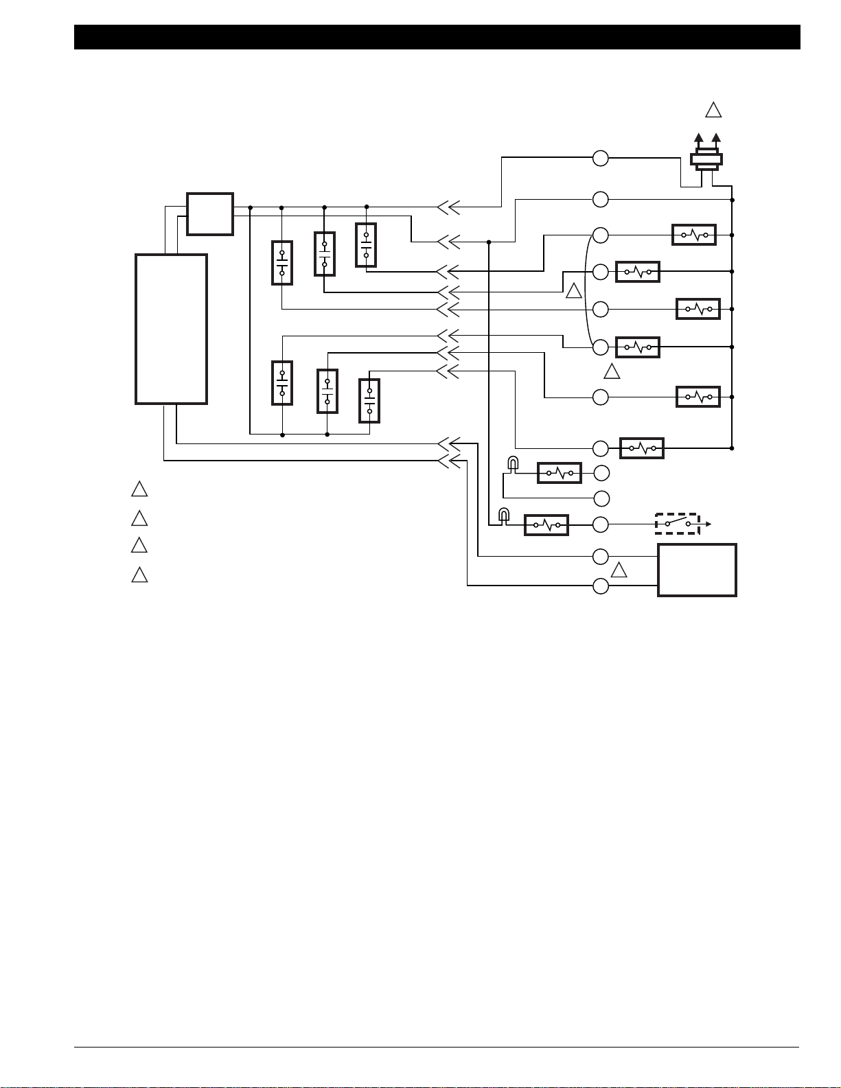
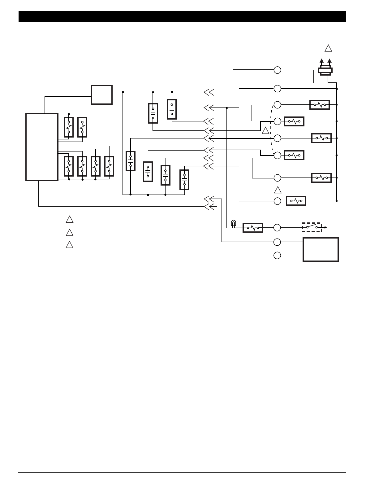
HEAT PUMP THERMOSTAT CROSS REFERENCE/SELECTION GUIDE
1
L1
L2
(HOT)
R
POWER
SUPPLY
THERMOSTAT
LOGIC
Y
POWER SUPPLY. PROVIDE DISCONNECT MEANS AND OVERLOAD
1
PROTECTION AS REQUIRED.
WIRES TO OT TERMINALS SHOULD NOT SHARE CABLE WITH OTHER
2
CONNECTIONS.
3
INSTALLER CONFIGURABLE. FACTORY DEFAULT IS O-ENERGIZED IN
COOL MODE.
4
FACTORY-INSTALLED JUMPER; REMOVE IF A HEAT RELAY IS CONNECTED
TO W1.
W2
E
O/B
W1
G
4
FAIL LED (RED)
CHECK LED (RED)
C
W1
AUXILIARY
HEAT RELAY
W2
E
COMPRESSOR
CONTACTOR
Y1
3
O/B
G
X1
X2
L
OT
2
OT
COMPRESSOR
CONTACTOR HEAT
EMERGENCY
HEAT RELAY
CHANGEOVER
VALVE
FAN RELAY
COMPRESSOR
MONITOR
OUTDOOR
SENSOR C7089B
TO R
M13250
Fig. 31. Typical wiring diagram for T8611G2002 and T8611G2028.
70-6627 • 25
Page 28
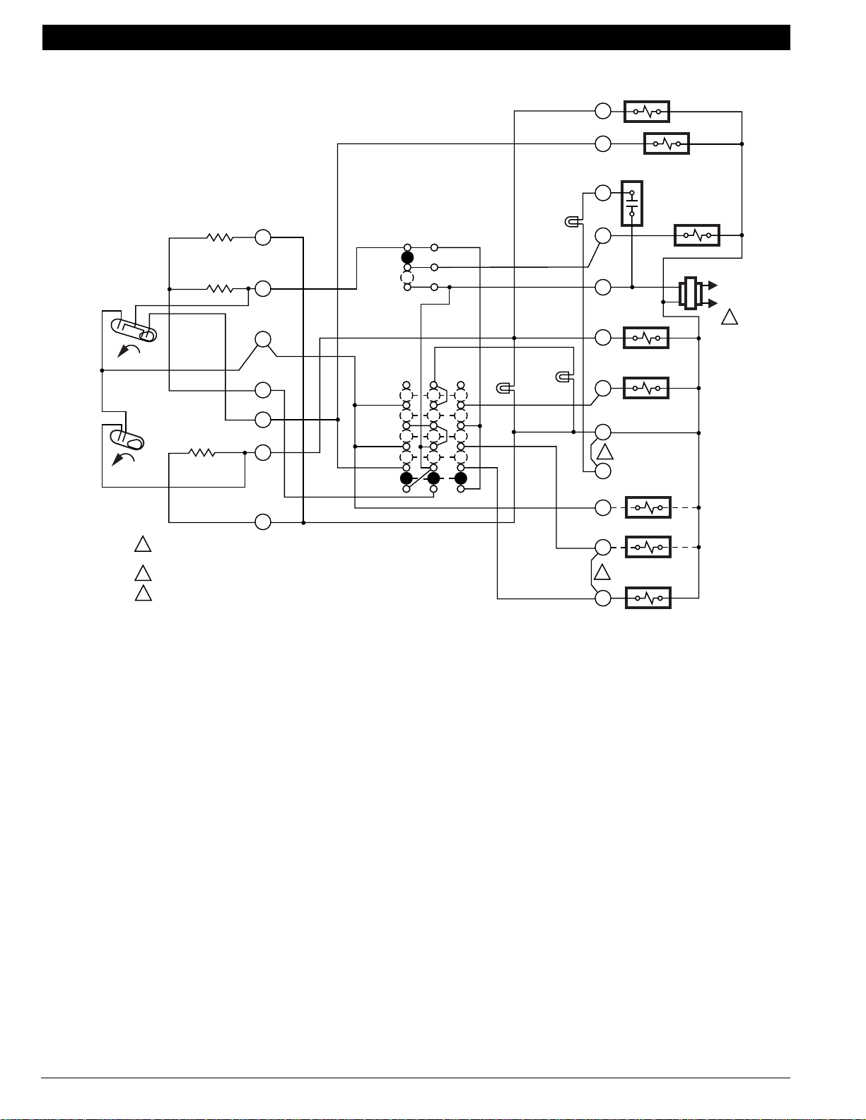
HEAT PUMP THERMOSTAT CROSS REFERENCE/SELECTION GUIDE
Electronic Thermostat (T8011, T8411, T8511, T8611)
Sequences of Operation
T8011 Programmable Heat Pump Thermostat and
T8411 Electronic Heat Pump Thermostat
Sequence of Operation
The Fan, Heat and Cool outputs are relay controlled. A loss of ac power, or a change in the SYSTEM switch setting can cause the
outputs to turn off. Table 2 shows the sequence of operations for the Fan settings and System modes.
Table 2. T8011 and T8411 Sequence of Operation.
FAN Switch Settings SYSTEM Switch Settings Call for Action Energize Terminals Display Icons
Auto Cool None O None
Auto Cool Cooling O, Y, G
Auto Heat None B
Auto Heat Stage 1 Heat B, W1, G
Auto Heat Stage 2 Heat B, W1, W2, G , Aux Ht
Auto Em. Ht. None L Em Ht indicator
Auto Em. Ht. Stage 1 Heat L, E, G , Em Ht indicator
Auto Em. Ht. Stage 2 Heat L, E, W2, G , Em Ht and Aux
None
indicator
Ht indicators
70-6627 • 26
Page 29
HEAT PUMP THERMOSTAT CROSS REFERENCE/SELECTION GUIDE
T8511 Deluxe Electronic Heat Pump Thermostat
Sequence of Operation
The thermostat energizes specific terminals depending on the Fan and System Settings. The LCD will display symbols and words to
report the condition of system. See Table 3 for specific information.
Table 3. T8511G Sequence of Operation for Separate Compressor Terminal (Y and W1) Models.
Fan Selection System Selection Call Energize Display Icons
Auto Off None None None
On Off Fan G
Auto Cool None O/B
Auto Cool or Auto Cooling O/Ba, G, Y1 and
Auto Heat None O/B
Auto Heat or Auto Stage 1 heating O/Ba, W1, G and
Auto Heat or Auto Stage 2 heating O/Ba, W1, W2, G , , and Aux Ht
Auto Em Heat None O/B
Auto Em Heat Stage 1 heating O/Ba, E, G , and Em Ht
Auto Em Heat Stage 2 heating O/Ba, E, W2, G , , Em Ht and
Auto Auto None O/B
a
Configure O/B (Select Models) in Installer Setup.
a
a
a
a
None
None
Em Ht
Aux Ht
None
70-6627 • 27
Page 30
HEAT PUMP THERMOSTAT CROSS REFERENCE/SELECTION GUIDE
T8611 Chronotherm IV Deluxe Programmable Heat Pump Thermostat
Sequence of Operation
The thermostat energizes specific terminals depending on the Fan and System Settings. The LCD will display the time, room
temperature, system and fan selection. Symbols will be displayed when the heating, cooling or fan is energized. See Table 4 for
specific information.
NOTE: Terminals listed in the Energize column vary depending on model.
Table 4. Heat Pump System Sequence of Operation.
Selection
Fan System Call Energize Display Icons
Auto Off None None None
On Off None G
Auto Cool None O or O/B
Auto Cool or Auto Stage 1 Cooling O or O/B
G and Y1
Auto Heat None B or O/B
Auto Heat or Auto Stage 1 heating B or O/Ba with W1 and G and
Auto Heat or Auto Stage 2 heating B or O/Ba with W2, W1 and G , , and Aux Ht
Auto Em Heat None B or O/B
Auto Em Heat Stage 1 heating B or O/Ba, E and G
(select models)
Auto Em Heat Stage 2 heating B or O/Ba, E and W2 and G
(select models)
Auto Auto None O/Ba, O or B
a
Configure O/B (select models) in Installer Setup.
b
Based on last piece of equipment called (cooling = O or heating = B) and Installer Setup selection.
a
a
a
a
with
None
and
None
Em Ht
, and Em Ht
, , Em Ht and Aux Ht
b
None
70-6627 • 28
Page 31

HEAT PUMP THERMOSTAT CROSS REFERENCE/SELECTION GUIDE
Thermostat Manufacturer Cross Reference
MANUFACTURER MODEL NUMBER HONEYWELL REPLACEMENT
American Stabilisa HP-1 T841A1712, Y594R1425, Y594G1419, T8411, T8511, T8011,
HP-1EF T841A1712, Y594R1425, Y594G1419, T8411, T8511, T8011,
HP-10EF
b
HP-15 Y594G1252, T8411, T8511, T8011, T8611R, T8611G,
a
See page 37 for hookup details.
b
Compressor protection is generally provided by the equipment manufacturer.
MANUFACTURER MODEL NUMBER HONEYWELL REPLACEMENT
Carrier Totaline
b,c
Multistage Heat Pump MP10/11 T8611G
MP30 T8611M
MS10/11 Y594R1425
MS12/13 T841A1316
MS20/21 Y594G1419
a
Use with ST82 Time Delay Relay for extended fan operation.
b
See pages 42-45 for hookup details.
c
Carrier thermostats manufactured by American Stabilis.
T8611R, T8611G
T8611R, T8611G
T841A1712, Y594R1425, Y594G1419, T8411, T8511, T8011,
T8611R, T8611G
a
MANUFACTURER MODEL NUMBER HONEYWELL REPLACEMENT
a
Climate Technology Corporation CTC400 T841A1316, Y594G1419, T8411, T8511, T8011, T8611
CTC403 T841A1316, Y594G1419, T8411, T8511, T8011, T8611,
a
Use T8611M or W8900B for 3 heat, 2 cool applications.
MANUFACTURER MODEL NUMBER HONEYWELL REPLACEMENT
Enerstat
b
DSP400 T841A1001a
DSP410 T841A1001a
DSP600 T874W1031/Q674L1546, Y594W1014
a
Provision for optional remote sensor, not provided.
b
See page 49 for hookup details.
70-6627 • 29
Page 32

HEAT PUMP THERMOSTAT CROSS REFERENCE/SELECTION GUIDE
MANUFACTURER MODEL NUMBER HONEYWELL REPLACEMENT
General Electric
a
See pages 57-58 for hookup details.
MANUFACTURER MODEL NUMBER HONEYWELL REPLACEMENT
a
Lennox
a
See pages 75-81 for hookup details.
a
3AAT86B21A1 Y594G1161, T8411, T8511, T8011, T8611
3AAT86B14A1 T841A1316, Y594R1425, T8411, T8511, T8011, T8611
3AAT86B16D1 T841A1316, Y594R1425, T8411, T8511, T8011, T8611
3AAT80A1A1 T841A1712, Y594R1425, T8411, T8511, T8011, T8611
3AAT80A2A1 T841A1712, Y594R1425, T8411, T8511, T8011, T8611
3AAT80B1A1 Y594G1161, T8411, T8511, T8011, T8611
3AAT86B1A1 Y594G1161, T8411, T8511, T8011, T8611
51H3901
T841A1316, Y594R1425, T8411, T8511, T8011, T8611G
(3AAB83C38)
51H4001
T841A1712, Y594G1419, T8411, T8511, T8011, T8611G
(3AAT88D38B2)
51H4301
T8611M, PC8900A1007/W8900B1002
(3AAT88D38C2)
21J7101
(3AAT89B38D1)
21J7201
T841A1555, Y594R1763, Y594G1161, T8411, T8511, T8011,
T8611G
T841A1712, Y594R1425, T8411, T8511, T8011, T8611G
(3AAT89B38E1)
21J7301
T841A1712, Y594G1419, T8411, T8511, T8011, T8611G
(3AAT89B38F1)
MANUFACTURER MODEL NUMBER HONEYWELL REPLACEMENT
Maple Chase 09520 T841A1316, Y594R1425, Y594G1419, T8411, T8511, T8011,
T8611G
09620 T8611M, PC8900A1007/W8900B1002
09720 T8611M, PC8900A1007/W8900B1002
MANUFACTURER MODEL NUMBER HONEYWELL REPLACEMENT
a
Seco
TA2000 T841A1001, Y594R1425, Y594G1419, T8411 T8511, T8011,
T8611
TA2010 T841A1001, Y594R1425, Y594G1419, T8411 T8511, T8011,
T8611
TA2040 T841A1001, Y594R1425, Y594G1419, T8411 T8511, T8011,
T8611
TA2050 T841A1001, Y594R1425, Y594G1419, T8411
TA2060 T841A1555 plus C815A1005
a
See pages 92-93 for hookup details.
70-6627 • 30
Page 33

HEAT PUMP THERMOSTAT CROSS REFERENCE/SELECTION GUIDE
MANUFACTURER MODEL NUMBER HONEYWELL REPLACEMENT
a,b
Trane
Single-Stage Heat Pump
Multistage Heat Pump ASYSTAT651 Y594G1161, T8411, T8511, T8011, T8611
a
See pages 97-100 for hookup details.
b
Trane thermostats manufactured by General Electric or Honeywell.
BAY28X182/BAY28X185
(T874A1184/Q674B1141)
BAY28X182/BAY28X187
(T874A1184/Q674E1033)
BAYSTAT009
(T874A1085/Q674B1018)
AY28X138 Y594G1161, T8411, T8511, T8011, T8611
AY28X139 T841A1068, Y594R1763, T8411, T8511, T8011, T8611
AY28X164 T874D1165/Q674E1049
BAY28X138
(3AAT80B1A1),
BAY28X140,
BAYSTAT138
BAYSTAT239
(3AAT86B1A1),
BAY28X139,
BAY28X141,
BAY28X153A,
(3AAT83F1B2)
BAYSTAT240 (3AAT80A1A1)
BAYSTAT339
(Y594R1284)
BAYSTAT024B T8611M, PC8900A1007/W8900B1002
TAYSTAT500 T8611R, T8611G
T874A1036/Q674B1075
T874A1036/Q674C1058
T874A1036/Q674B1018
Y594G1161, T8411, T8511, T8011, T8611
T841A1068, Y594R1763, T8411, T8511, T8011, T8611
T841A1068, Y594R1763, T8411, T8511, T8011, T8611
70-6627 • 31
Page 34

HEAT PUMP THERMOSTAT CROSS REFERENCE/SELECTION GUIDE
MANUFACTURER MODEL NUMBER HONEYWELL REPLACEMENT
White Rodgersa
Single-Stage Heat Pump
Multistage Heat Pump IC70-18 T841A1001, Y594G1252
a
See page 108 for hookup details.
IF56-444 T8034C1234
IF93-36 T8600C1162
IC70-24 T874D1165/Q674F1022
IC71-2 Y594G1419
IF58-910/S28-1 T841A1217, Y594R1300
IF58-910/S28-2 T841A1423, Y594R1615
IF58-910/S28-16 T841A1316, Y594R1425
IF58-911/S28-5 T841A1316, Y594G1419
IF58-911/S28-17 T841A1001, Y594G1252
IF58-911/S28-18 T841A1068, Y594R1136
IF58-56 T841A1050, Y594R1425
IF58-57 T841A1068, Y594R1136
IF58-58 T841A1217, Y594R1425
IF58-72 T841A1233, Y594R1615
IF58-77 T841A1316, Y594R1425
IF58-78 T841A1217, Y594R1425
IF58-83 T841A1217, Y594R1243
IF59-79 T841A1316, Y594R1425
IF60-25 T8600C1162
IF62-21 T8411, T8511, T8011, T8611R, T8611G
IF82-79 T8411, T8511, T8011, T8611R, T8611G
IF91-71 T8611M, PC8900A1007/W8900B1002
IF92-71 T8611M, PC8900A1007/W8900B1002
IF94-71 T8611M, PC8900A1007/W8900B1002
IF95-71 T8611M, PC8900A1007/W8900B1002
70-6627 • 32
Page 35

HEAT PUMP THERMOSTAT CROSS REFERENCE/SELECTION GUIDE
Tips for Using This Heat Pump Cross Reference
This cross reference, alphabetized by equipment or thermostat manufacturer, provides the information needed to
choose and wire the Honeywell electromechanical, Chronotherm III, or electronic heat pump thermostats in new
installations and replacement applications. It also gives you the opportunity to upgrade the system from a standard to a
deluxe thermostat for improved performance and from manual changeover to the convenience of automatic heat/cool
changeover and to a Chronotherm® IV thermostat that puts the heat pump to work to save money. Best of all, you can
upgrade to the PC8900/W8900B1002 Perfect Climate Comfort Center™ Control System. This
controls temperature, indoor air quality, ventilation, humidity, and zoning.
To use this Cross Reference:
1. Identify heat pump equipment manufacturer and refer to those diagrams in this reference.
2. Identify existing
logo, and try to match up for verification. Some typical thermostats and subbases are listed in each section to make
identification easier. The Honeywell model number is listed, followed by the equipment manufacturer model number,
if available.
3. Make a listing of wiring terminals used and wire colors. You may want to write on the appropriate diagram in this
cross reference.
4. Note the unique control requirements your heat pump may have.
— Determine reversing valve (changeover) mode. O terminal cool or B terminal heat is typical.
— Identify first stage heat terminal. Connect to Y if a common terminal is used for first stage heat and cool, or to
W1 if a separate terminal is used for first stage heat.
— Identify if device has manual or automatic changeover from heat to cool.
— Identify what action, if any, is required for LED selection; e.g., auxiliary heat, emergency heat, check, or fail.
5. Select a replacement based both on the technical requirements and your customer’s needs; e.g., a working family
may find a Chronotherm® IV upgrade desirable.
6. After selecting the proper thermostat, use the corresponding control hookup diagram. See example below.
subbase
model number if made by Honeywell, even if thermostat has equipment manufacturer’s
one
comfort center
Existing
Control
Terminal
Designation
CXC C C C
RRR R R R
7. Connect only those terminals shown with lines to them on the diagram. Some terminals on the new thermostat may
not be used.
8. Refer to the following two pages for an example of a typical cross reference diagram and the associated footnotes.
Electromechanical
Thermostat
Hook wire
previously
on C to X
Hook wire
previously
on R to R
Chronotherm III
Thermostat
or to
or to
or to
or to
Electronic
Replacement
or Upgrade
Chronotherm IV
Thermostat
or to
or to
Perfect Climate
Comfort Center
Control System
or to
or to
M13251
70-6627 • 33
Page 36

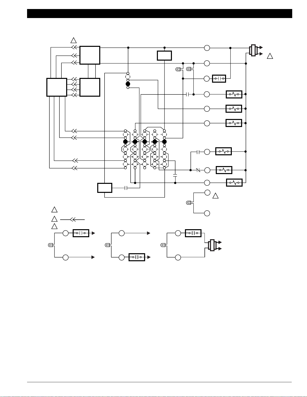
HEAT PUMP THERMOSTAT CROSS REFERENCE/SELECTION GUIDE
Electronic Replacement or Upgrade
Chronotherm
IV
Electronmechanical
Chronotherm®
III
Function
Common
Compressor
System Monitor/
Sytem Defrost
A
Power
1st Stage
Heat
M
Auxiliary
Heat
Fan
C/O V alve
Heat
C/O V alve
Cool
KL
PC8900/
W8900B1002
L
T841A1712
Y594R1425
Y594G1419
Y594G1476
XX X C CCCC C C
T8611R1000
T8611G1004
T8411R1002
T8411G1028
T8511G1021
T8511G1047
T8011R1006
T8011R1014
T8611G2002
T8611G2028
T8611M1002
T8611M2017
T8611M2025
RR R R RRRR R R
Y Y Y1 Y1 or Y Y Y1 Y Y1 Y1
I
I
I
– W1 W1 W1 W1 W1 W1 W1
I
II
I
––
W2 W2 W2 W2 W2 W2 W2 W2 Y2 Aux.
GG G G GGGG G G
P
BB B B BB or
OO O O OO or
–L LLLLLLL
G
H
P
P
C
O/B
C
O/B
H
G
P
BB or
OO or
H
P
O/B
O/B
G
P
C
C
B or
O/B O/B
O or
O/B O/B
GH
C
C
E
Y1/W1
F
P
C
C
G
Em. Heat
Multiple
Heat
Loads
B
LED Indication
Defrost
2nd Stage
Compressor
2nd Stage
Cool in two
Stage System
EE E E EEEE E E
W3 W3 W3 W3
–X2
D
X1 X2 X1 X2
–– – P –––– – –
J
D
N
J
–––
J
–– – – ––––
–– – – –––– –
J
J
D
D
X1 X2 X1 X2
Y2 W2
J
–
F
Y2
M13245
O
70-6627 • 34
Page 37

HEAT PUMP THERMOSTAT CROSS REFERENCE/SELECTION GUIDE
A Terminal must be connected to the transformer common.
B Terminal is for multiple auxiliary heat loads such as contactors, sequencers, or relays.
C Configure O/B (Select Models) in Installer Setup.
D Optional LED indication activated with completed circuit on X1 and X2 terminals.
E If separate Y1 and W1 terminals are required, install R8222D1014; (See page 12.)
F When W2 is not used, configure W2 cycle rate to NC.
G LED is energized when terminal is powered.
H L terminal is powered continuously when thermostat is in Em. Ht. position.
I Do not remove factory-installed jumper.
J If multiple auxiliary heat loads are used, connect to W2 (Aux W8900B) terminal.
K Used on two-speed compressor heat pump applications.
L Used on heat pumps that energize the compressor on both first stage cooling and first stage heating through a common Y
terminal.
M Q674F1022 switching subbase available when separate first stage heat and cool terminals are required. See specific heat pump
manufacturer’s listing for hookup information.
N P terminal on T8611R1000 only. Energized in heating and cooling modes; shown only when used.
O Jumper W2 and Y2 if stage 2 heating and cooling are common.
P To change fan operation in Emergency Heat mode, see page 9.
X1
CHECK
LED
(YELLOW)
FAULT DETECTION
SWITCH
X2
SWITCH TO R (POWER) SIDE
OF SYSTEM TRANSFORMER
TO R
TO C/X
X1
CHECK
LED
(YELLOW)
SWITCH TO C (COMMON) SIDE
OF SYSTEM TRANSFORMER
FAULT DETECTION
SWITCH
X2
TO C/X
TO R
CHECK
LED
(YELLOW)
SWITCH IN SECONDARY OF
SEPARATE TRANSFORMER
X1
X2
SWITCHING
DEVICE
24 VAC
L1
(HOT)
L2
M13246
70-6627 • 35
Page 38

AMANA
Models: RHA1842A, RHA (24-42)A2A, RHA (48-60)A2A, RHA (36, 48, 60)A3A & A4A, RHD (18-24)A2A, RHD (30-60)A2A,
RHE (18-24)A2A, RHE (30-60)A2A, RHA (36, 48, 60)A3B & A4B.
Electronic Replacement or Upgrade
Electromechanical
Chronotherm
III
®
Chronotherm
IV
Function
Common
Compressor
1st Stg. Heat
System Monitor/
System Defrost
C
Power
Aux. Heat
Fan
C/O V alve
Cool
C/O V alve
Heat
Em. Heat
Existing
Terminals
or
X
X1 or C
T841A1712
Y594R1425
Y594G1419
Y594G1476
T8611G1004
T8611R1000
T8411R1002
T8411R1028
T8511G1021
T8511G1047
T8011R1006
T8011R1014
T8611G2002
T8611G2028
XXX C CCCCC
PC8900/
W8900B1002
RRRR R RRR RR
YYYY1Y1
B
B
B
Y Y Y1 Y Y1
B
B
B B
B
W1 – W1 W1 W1 W1 W1 W1 W1
W2 W2 W2 W2 W2 W2 W2 W2 W2 Aux.
or
Y1/W1
–
D
I
GGGG G GGG GG
H
OOOO O O O
or
O/B
OO
H
or
O/B O/B
H
H
BBBB B BB
or
O/B
BB
H
or
O/B O/B
H
EEEE E EEE EE
A
L L L LLL LL
J
F
F
J
F
J
J
Multiple Aux.
A
W3 W3 W3 W3
Heat Loads
LED
Indication
Defrost
2nd Stage
––
A
P––– – ––– ––
–––– – ––– –
E
X2 X1 X2 X1 X2
Compressor
2nd Stage
–––– – ––– –
Cool
A Not available on all models.
B Do not remove factory-installed jumper.
C Terminal must be connected to the transformer common.
D If separate Y1 and W1 terminals are required, install R8222D1014.
See page 12.
E Field-installed X2 to X jumper.
TYPICAL THERMOSTATS AND SUBBASES — HONEYWELL MODEL NUMBER (CUSTOMER PART NUMBER)
T841A1241 (D99458003) T8611R1083 (D9807605) T874R1194/Q674L1249
G
G
G
G
–– –
G
X1 X2
G
–
W2
Y2
F L terminal is powered continuously when thermostat is in Em. Ht. position.
G If multiple auxiliary heat loads are used, connect to W2 (Aux W8900B)
terminal.
H Configure O/B (select models) in Installer Setup.
I When W2 is not used, configure W2 cycle rate to NC.
J LED is energized when terminal is powered.
M13172
I
70-6627 • 36
Page 39

AMERICAN STABILIS
TYPICAL THERMOSTATS AND SUBBASES: HP1, HP1EF, HP10EF, HP15
Function
Common
Compressor
1st Stg. Heat
System Monitor/
System Defrost
E
Power
Aux. Heat
Fan
C/O V alve
Heat
C/O V alve
Cool
Electromechanical
Chronotherm
Existing
Terminals
T841A1712
Y594R1425
Y594G1419
Y594G1476
C XXX C CCC CC
T8611R1000
T8611G1004
T8611M7008
®
III
T8411R1002
Electronic Replacement or Upgrade
T8411R1028
T8511G1021
T8511G1047
T8011R1006
T8011R1014
Chronotherm
IV
T8611G2002
T8611G2028
PC8900/
W8900B1002
R RRR R RRR RR
Y1 Y Y1 Y1 Y1
––
W1 W1 W1 W1 W1 W1 W1
G
G
or
Y Y Y1 Y Y1
G
G
G
G
G
Y1/W1
–
B
W2 W2 W2 W2 W2 W2 W2 W2 W2 Aux.
G GGG G GGG GG
A
or
or
O/B
O/B
C
A
BBBB B BB
OOOO O OO
X LX1 L LLL LL
CC
D
D
B B
OO
D
A
or
O/B O/B
A
or
O/B O/B
C
A
A
C
EM. Heat
Multiple Aux.
E EEE E EEE EE
–
W3 W3 W3
Heat Loads
LED
Indication
2nd Stage
H
––
X2 X2 X1 X2
– ––– – ––– –
H
Compressor
A Confgure O/B (select models) in Installer Setup.
B When W2 is not used, configure W2 cycle rate to NC.
C LED is energized when terminal is powered.
D L terminal is powered continuously when thermostat is in Em. Ht. position.
E Terminal X (C) must be connected to transformer common.
– ––– ––
F
F Optional CHECK LED on T8611G,M. Connect X to X1; jumper X2 to C.
See Fig. 26 and 27.
G Field-installed W1 to Y1 jumper (provided).
H Field-installed X2 to X jumper (provided).
–– –
X1 X2
–
W2
M13142
B
70-6627 • 37
Page 40

ARMSTRONG/AIR-EASE
Electromechanical
Chronotherm
III
Electronic Replacement or Upgrade
®
Chronotherm
IV
Function
Common
Compressor
1st Stg. Heat
System Monitor/
System Defrost
E
Power
Aux. Heat
Fan
C/O V alve
Heat
C/O V alve
Cool
Existing
Terminals
or
X
C X X X C C C C C C
T841A1712
Y594R1425
Y594G1419
Y594G1476
T8611R1000
T8611G1004
T8411R1002
T8411R1028
T8511G1021
T8511G1047
T8011R1006
T8011R1014
T8611G2002
T8611G2028
PC8900/
W8900B1002
RRRR R RRRRR
Y Y Y Y1 Y1
F F
W1
–
F
W1 W1 W1 W1 W1 W1 W1
F
or
Y Y Y1 Y Y1
F
FF
F
W2 W2 W2 W2 W2 W2 W2 W2 W2 Aux.
Y1/W1
–
J
G
GGGG G GGGGG
A
BBBB B BB
OOOO O OO
L LX1 L LLL LL
B
B
C
or
O/B
A
or
O/B
C
B
B B
OO
C
A
or
O/B O/B
A
or
O/B O/B
B
A
A
B
EM. Heat
Multiple Aux.
Heat Loads
LED
Indication
Defrost
2nd Stage
D
EEEE E EEEEE
W3 W3 W3 W3
––
X2 X2 X1 X2
H
H
P – –– P ––– ––
–––– – ––––
Compressor
A Configure O/B (select models) in Installer Setup.
B LED is energized when terminal is powered.
C L terminal is powered continuously when thermostat is in Em. Ht. position.
D Terminal is for multiple second stage loads such as contactors,
sequencers, or relays.
E Terminal X or C must be connected to transformer common.
F Do not remove factory-installed jumper.
TYPICAL THERMOSTATS AND SUBBASES — HONEYWELL MODEL NUMBER
T8611R1182 T841A1597
A
––– ––
I
K
–––
X1 X2
–
W2
G When W2 is not used, configure W2 cycle rate to NC.
H Field-installed X2 to X jumper (provided).
I Optional CHECK LED on T8611G1004. See Fig. 26.
J If separate Y1 and W1 terminals are required, install R8222D1014. See
page 12.
K Available on T8611R1000 only.
M13143
G
70-6627 • 38
Page 41

ARCOAIRE/SNYDER GENERAL/COMFORTMAKER
AYC, AYD, AYF
Function
Common
Compressor
1st Stg. Heat
C
Power
Aux. Heat
Fan
C/O V alve
Heat
C/O V alve
Cool
®
Electronic Replacement or Upgrade
Electromechanical
Existing
Terminals
X
or
C X X X C C C C C C
T841A1712
Y594R1425
or X1
R RRR R RRR RR
Y Y Y Y1 Y1
W1
or
W2
W1 W2 W2 W2 W2 W2 W2 W2 W2
–
W1 W1 W1 W1 W1 W1 W1
G GGG G GGG GG
B B B B B B B or
O O O O O O O or
E
Y594G1419
Y594G1476
E
III
T8611R1000
T8611G1004
Chronotherm
T8411R1002
T8411R1028
or
Y Y Y1 Y Y1
E
T8511G1021
T8511G1047
A
O/B
A
O/B
T8011R1006
Chronotherm
T8011R1014
EEE
B B or
OO or
IV
T8611G2002
T8611G2028
E
A
O/B O/B
A
O/B O/B
PC8900/
W8900B1002
Y1/W1
–
B
Aux.
A
A
K
System Monitor/
System Defrost
EM. Heat
Multiple Aux.
Heat Loads
LED
Indication
D
Defrost
2nd Stage
Compressor
A Configure O/B (select models) in Installer Setup.
B When W2 is not used, configure W2 cycle rate to NC.
C Terminal X (C, X1) must be connected to transformer common.
D Terminal is for multiple second stage loads such as contactors,
sequencers, or relays.
E Do not remove factory-installed jumper.
F Optional CHECK LED on T8611G1004. See Fig. 26.
G Field-installed X2 to X jumper (provided).
T841A1142 (1506726) T841A1159 (1505726) T874D1603
T874G1592/Q674F1212 T874G1782/Q674J1175 (1506756) T874G1774/Q674J1175 (1505756)
T874R1301/Q674L1181 (1505714) T874R1483/Q674L1538 (1505721) T874R1517/Q674L1538 (1506721)
T874R1525/Q674L1181 T874R1574/Q674L1538 T874R1582/Q674L1538 (A02077)
T874R1723/Q674L1702 (654958B07) T8611R1067 (1506-744) T8611R1075 (1505-744)
T8300A1193/Q6300A
or
L
X LX1 L LLL LL
E EEE E EEE EE
–
W3 W3 W3
––
P ––– P ––– ––
–––– – ––– –
TYPICAL THERMOSTATS AND SUBBASES — HONEYWELL MODEL NUMBER (CUSTOMER PART NUMBER)
I
G
X2 X2 X1 X2
I
G
L
H
F
J
H If multiple auxiliary heat loads are used, connect to W2 (Aux W8900B)
terminal.
I LED is energized when terminal is powered.
J Available on T8611R1000 only.
K If separate Y1 and W1 Terminals are required, install R8222D1014.
See page 12.
L L terminal is powered continuously when thermostat is in Em. Ht. position.
L
HH H HH
–––
I
L
I
X1 X2
I
–
B
W2
M13144
70-6627 • 39
Page 42

BARD
Models: 24UHPQC, 30UHPQC, 42UHPQC, 48UHPQB, 48UHPQB-B, 48UHPQC-B, 60UHPQC-B
Function
Common
Compressor
1st Stg. Heat
E
Power
Aux. Heat
Fan
C/O V alve
Heat
C/O V alve
Cool
®
Electromechanical
Existing
Terminals
C
or
T841A1712
X X X X C C C C C C
Y594R1425
Y594G1419
Y594G1476
III
T8611R1000
T8611G1004
Chronotherm
T8411R1002
T8411R1028
Electronic Replacement or Upgrade
Chronotherm
IV
T8511G1021
T8511G1047
T8011R1006
T8011R1014
T8611G2002
T8611G2028
PC8900/
W8900B1002
or X1
Rh
RRRR R RRR RR
or
Rc
Y Y Y Y1 Y1 or Y Y Y1 Y Y1
F
F
––
W1 W1 W1 W1 W1 W1 W1 –
F
F
FF
Y1/W1
F
W2 W2 W2 W2 W2 W2 W2 W2 W2 Aux.
GGGG G GGGGG
A
O/B O/B
A
O/B O/B
A
A
B or
W1
BBB B BB or
OOOO O OO or
A
O/B
A
O/B
B B or
OO or
B
System Monitor/
System Defrost
EM. Heat
Multiple Aux.
Heat Loads
LED
D
Indication
2nd Stage
Compressor
A Configure O/B (select models) in Installer Setup.
B When W2 is not used, configure W2 cycle rate to NC.
C If multiple auxiliary heat loads are used, connect to W2 (Aux W8900B)
terminal.
D Terminal is for multiple second stage heating loads such as contactors,
sequencers, or relays.
L LX1 L LLL LL
EEEE E EEEEE
W3 W3 W3 W3
––
–––– – ––––
IJ
H
X2 X2 X1 X2
I
H
C
G
J
C
I
C
–––
C
J
I
C
X1 X2
C
–
W2
E Terminal X (C, X1) must be connected to transformer.
F Do not remove factory-installed jumper.
G Optional CHECK LED on T8611G1004. See Fig. 26.
H Field-installed X2 to X jumper (provided).
I LED is energized when terminal is powered.
J L terminal is powered continuously when thermostat is in Em. Ht. position.
M13145
I
B
70-6627 • 40
TYPICAL THERMOSTATS AND SUBBASES — HONEYWELL MODEL NUMBER
T872N1036/Q672F1299
T872N1164/Q672L1185
T874N1024/Q674F1261
T874R1129/Q674L1181
T874R1152/Q674L1207
Page 43

B.D.P. (BRYANT-DAY/NIGHT-PAYNE)
Function
Common
Compressor
1st Stg. Heat
System Monitor/
System Defrost
F
Power
Aux. Heat
Fan
C/O V alve
Heat
C/O V alve
Cool
®
Electronic Replacement or Upgrade
M
T8411R1002
T8411R1028
G
M
T8511G1021
T8511G1047
G
A
O/B
A
or
O/B
K
Chronotherm
T8011R1006
T8011R1014
G
B B or
O O or
M
IV
T8611G2002
T8611G2028
G
A
O/B O/B
A
O/B O/B
K
PC8900/
W8900B1002
Y1/W1
–
B
A
A
K
Electromechanical
Existing
Terminals
C1
or C X X X C C C C C C
X1
T841A1712
Y594R1425
R RRR R R R RR R
W1
or Y Y1 Y Y1 Y1 or Y Y Y1 Y Y1
––
W1 W1 W1 W1 W1 W1 W1
W2 W2 W2 W2 W2 W2 W2 W2 W2 A ux.
G GGG G G G GG G
B B B B B B B or
Y1 or O O O O O O O
L or F L L L L L L L
G
K
Y594G1419
Y594G1476
G
III
T8611R1000
T8611G1004
G
Chronotherm
EM. Heat
Multiple Aux.
Heat Loads
Defrost
LED
Indication
2nd Stage
X or E E E E E E E E E E
C
D
W3 W3 W3 W3
E
P ––– P – – –– –
I
X–
X2 X1 X2 X1 X2
– ––– – – – ––
Compressor
A Configure O/B (select models) in Installer Setup.
B When W2 is not used, configure W2 cycle rate to NC.
C If provided on original equipment.
D Terminal is for multiple second stage heating loads such as contactors,
sequencers, or relays.
E Model 545 typical. P terminal provided on T8611R1000 only.
F Terminal X (C, X1, C1) must be connected to transformer common.
G Do not remove factory-installed jumper.
TYPICAL THERMOSTATS AND SUBBASES — HONEYWELL MODEL NUMBER (CUSTOMER PART NUMBER)
T872G1166/Q672F1125
T872G1174/Q672F1125
T874G1261/Q674F1253
T874G1451 (HH641502)/Q674F1212
J
E
L
T874J1010/Q674J1084 (34427DP124/P272-2471/34427DP126,P272-1879)
T874J1010/Q674L1371 (34427DP124/P272-2471/34427DP125,P272-1878)
T874R1004/Q674B1042
T874R1335 (HH641501)/Q674L1405
H
H Optional CHECK LED on T8611G1004. See Fig. 26.
I Field-installed X2 to X jumper (provided).
J If multiple auxiliary heat loads are used, connect to W2 (Aux W8900B)
terminal.
K LED is energized when terminal is powered.
L Optional Check
M L terminal is powered continuously when thermostat is in Em. Ht. position.
J
–––
LED
J
J
J
X1 X2
activated with completed circuit on X1 and X2 terminals.
L
J
–
B
W2
M13146
70-6627 • 41
Page 44

CARRIER
TYPICAL 50YQ, QT; 38QF, QN, QB, NPHPO1, 38YRA
Function
Common
Compressor
1st Stg. Heat
System Monitor/
System Defrost
E
Power
Aux. Heat
Fan
C/O V alve
Heat
C/O V alve
Cool
Electronic Replacement or Upgrade
T8411R1028
T8511G1021
T8511G1047
T8011R1006
T8011R1014
Chronotherm
IV
T8611G2002
T8611G2028
PC8900/
W8900B1002
Existing
Terminals
Electromechanical
T841A1712
Y594R1425
Y594G1419
Y594G1476
Chronotherm
III
T8611R1000
T8611G1004
®
T8411R1002
C X XX C CC CC C
RR RR R RR RR R
Y Y Y Y1 Y1
F
W1
W1
or
W2 W2 W2 W2 W2 W2 W2 W2 W2 Aux.
–
W1 W1 W1 W1 W1 W1 W1
F
or
Y Y Y1 Y Y1
F
FF
F
F
Y1/W1
–
B
GG GG G GG GG G
A
or
or
O/B
A
O/B
II
B B B B B B B
O O O O O O O
C
or
F
LLX1LLLLLL
I
K
K
B B
OO
K
A
or
O/B O/B
A
or
O/B O/B
I
A
A
I
EM. Heat
Multiple Aux.
Heat Loads
LED
Indication
Defrost
2nd Stage
D
EE EE E EE EE E
–
––
W3 W3 W3
H
X2 X2 X1 X2
H
P– –– P –– –– –
–– –– – –– ––
Compressor
A Configure O/B (select models) in Installer Setup.
B When W2 is not used, configure W2 cycle rate to NC.
C If provided on original equipment.
D Terminal is for multiple second stage loads such as contactors, sequencers,
or relays.
E Terminal X (C) must be connected to transformer common.
F Do not remove factory-installed jumper.
T841C1009 (HH07AT180)
TYPICAL THERMOSTATS AND SUBBASES — HONEYWELL MODEL NUMBER (CUSTOMER PART NUMBER)
T872G1075/Q672J1054 (HH07AT171/HH93AZ173)
T872G1075/Q672L1052 (HH07PZ085/HH93AZ075A)
T874C1166 (HH07AT160)
T874D1272 (HH07AT162)
T874G1055/Q674J1035 (HH07AT171/HH93AZ173A)
T874G1055/Q674J1118 (HH07AT171/HH93AZ188)
T874G1055/Q674L1041 (HH07AT171/HH93AZ175A)
T874G1055/Q674L1397 (HH07AT171/HH93AZ185A)
T874G1055/Q674P1005 (HH07AT171/HH93AZ169)
T874G1071/Q674P1005 (HH07AT171/HH93AZ169)
T874G1121 (HH07AT161)
T874G1717/Q674J1167
T874H1070/Q674B1406 (HH07AT166/HH93AZ200)
T874H1070/Q674C1322 (HH07AT166/HH93AZ199)
T874H1088/Q674B1406 (HH07AT166/HH93AZ200)
T874H1088/Q674C1322 (HH07AT166/HH93AZ199)
T874J1002/Q674L1074 (HH07AT175/HH93AZ186)
T874L1000/Q674E1270 (HH07AT176/HH93AZ189)
T874L1018/Q674B1356 (HH07AT178/HH93AZ192)
T874L1018/Q674C1264 (HH07AT178/HH93AZ193)
––––––
G
J
G Optional CHECK LED on T8611G1004. See Fig. 26.
H Field-installed X2 to X jumper (provided).
I LED is energized when terminal is powered.
J Available on T8611R1000 only.
K L terminal is powered continuously when thermostat is in Em. Ht. position.
–––
T874R1319/Q674B1281 (42QH400083/42QH400103)
T874R1384/Q674L1439 (HH07AQ170/HH93AZ187)
T874R1384/Q674L1579 (HH07AQ170/HH93AZ198)
T874V1008/Q674R1003 (HH07AT177/HH93AZ190)
T8085R1007/Q682L1002 (HH07AT075/HH93AZ159C)
T8085R1023/Q682L1028 (HH07AT075C/HH93AZ159C)
T8141A1147
T8611G1046 (HH07AE001)
T8611R1208 (HH07AX114)
T8611R1216 (HH07AX115)
X1 X2
–
W2
M13147
B
70-6627 • 42
Page 45

Electromechanical
Chronotherm® III
CARRIER
TYPICAL 38BQ C
Electronic Replacement or Upgrade
Chronotherm IV
Function
Common
1st Stage Cool
1st Stage Heat
2nd Stage Heat
Common 1st Stage
Compressor
Power
Fan
C/O V alve
Cool
C/O V alve
Heat
Em. Heat
A
C
C
Existing
Terminals
T874D1165/
Q674F1022
T8611M7008
T8511M1002
T8611M2017
T8611M2025
PC8900/
W8900B1002
C X1 C C C C
RR RRRR
C
Y1 Y1
C
W1 W1
W2 W2 W2 Y2 Y2 W2
B
C
C
C
C
C
C
C
C
GG GGGG
C
–O O
C
–B B
EE EEEE
–– YY1Y1
B
C
E
O/B O/B O/B
O/B O/B O/B
C
E
C
C
C
Y1/W1
E
C
F
System Monitor/
–– LLLL
System Defrost
LED Indication
2nd Stage Cool
A Terminal must be connected to the transformer common.
B For auxiliary heat LED indication, jumper X2 to W2 on Q674. For emergency
heat LED indication, jumper X2 to E.
C Relay required (R8222B1067 typically) for T8511M, T8611M,
PC8900/W8900B1002 application. See page 9 for wiring diagram.
TYPICAL THERMOSTATS AND SUBBASES — HONEYWELL MODEL NUMBER (CUSTOMER PART NUMBER)
XX2
Y2 Y2 Y2 Y2 Y2 Y2
T874D1074/Q674F1030 (HHO7AT172/HH93AZ174)
T874D1074/Q674F1063 (HH07AT172/HH93AZ181)
B
G
D
X1 X2
D Optional LED indication activated with completed circuit on X1 and
X2 terminals.
E Configure O/B (select models) in Installer Setup.
F Configure Y1/W1 terminal in installer setup.
G L terminal is continuously energized in Em. Heat Mode.
H LED is energized when terminal is powered.
H
–
G
X1 X2
D
H
–
M13148
70-6627 • 43
Page 46

CARRIER
USES HONEYWELL Q674L1116 (HH93AZ171) SUBBASE
Electromechanical
Function
Common
B
Existing
Terminals
NOT
AVAILABLE
C X1 C C C C
NOT
AV AILABLE
T874D1165/
Q674F1022
Chronotherm
H
T8611M7008
®
III
Electronic Replacement or Upgrade
Chronotherm IV
T8511M1002
T8611M2017
T8611M2025
PC8900/
W8900B1002
Power
Compressor
1st Stg. Heat
2nd Stage
Compressor
Fan
C/O V alve
Heat
C/O V alve
Cool
System Monitor/
System Defrost
EM. Heat
2nd Stg. Cool
RRRRRR
G
Y Y1 Y Y1 Y1
–
Y1
E
W1
W2 W2 Y2 Y2 W2
G
–– – –
G
Y1/W1
GGGGGG
–BB
NOT AVAILABLE
OOO
LX2LLLL
NOT AVAILABLE
F
F
J
D
O/B O/B O/B
D
D
D
O/B O/B O/B
I
J
D
D
I
EEEEEE
A
–
Y2 Y2
A
––
Y2
A
LED
Indication
A Jumper Y2 to W2.
B Terminal C (X1) must be connected to transformer common.
C Optional CHECK LED on T8611M7008. Connect L to X1, jumper X2 to C.
D Configure O/B (select models) in Installer Setup.
E In this application, auxiliary heat and compressor two are both connected
to terminal Y1.
F For second stage compressor LED indication, jumper X2 to Y2 on Q674.
For emergency heat LED indication, jumper X2 to E. For system monitor
LED indication, connect L to X2.
––
TYPICAL THERMOSTATS AND SUBBASES — HONEYWELL MODEL NUMBER (CUSTOMER PART NUMBER)
T874D1264/Q674L1116 (HH07AT173/HH93AZ171)
70-6627 • 44
C
X1 X2
G Both first stage heat and cool are connected to Y or Y1/W1 terminal.
H When subbase system switch is in AUTO position, equipment operates in
cool mode only.
I LED is energized when terminal is powered.
J L terminal is powered continuously when thermostat is in Em. Ht. position.
–
X2
C
–
M13149
Page 47

Electromechanical
Chronotherm
CARRIER
TWO-SPEED COOLING COMPRESSORS
Electronic Replacement or Upgrade
®
III
Chronotherm IV
Function
Common
Compressor
Compressor
Heat Relay
System Monitor/
System Defrost
A
Power
1st Stg.
2nd Stg.
2nd Stg.
Fan
C/O V alve
Cool
C/O V alve
Heat
Existing
Terminals
NOT
AVAILABLE
NOT
AV AILABLE
NOT
AVAILABLE
T8611M7008
T8511M1002
T8611M2017
T8611M2025
PC8900/
W8900B1002
C C C C C
RRRRR
Y Y Y1 Y1
Y1/W1
Y2 Y2 Y2 Y2 Y2
W2 W2 W2
NOT AVAILABLE
NOT AVAILABLE
NOT AVAILABLE
E
E
GGGGG
OO
–B
LLLLL
D
B
O/B O/B O/B
B
O/B O/B O/B
C
B
B
D
B
B
C
EM. Heat
Multiple Aux.
EEEEE
–
Heat Loads
A Terminal C must be connected to transformer common.
B Configure O/B in Installer Setup.
C LED is energized when terminal is powered.
TYPICAL THERMOSTATS AND SUBBASES — HONEYWELL MODEL NUMBER (CUSTOMER PART NUMBER)
T874S1001/Q674F1501 (HH07AT201/HH93AZ215)
W3 W3 W3 Aux.
D L terminal is powered continuously when thermostat is in Em. Ht. position.
E If 2nd stage heat is auxiliary (electric resistive), connect auxiliary stage
to W3.
T8611T7000 (HH07AX112)
T8611T7018 (HH07AX113)
M13150
70-6627 • 45
Page 48

CRISPAIRE/MARVAIR
Function
Common
Compressor
1st Stg. Heat
A
Power
Aux. Heat
Fan
C/O V alve
Heat
C/O V alve
Cool
®
Electronic Replacement or Upgrade
Electromechanical
Existing
Terminals
XX X X C C C C C C
T841A1308
Y594R1797
RR R R R R R R R R
Y Y Y Y Y1
–– – –
W2 W2 W2 W2 W2 W2 W2 W2 W2 Aux.
GG G G G G G G G G
B B B B B B B
OO O O O OO
Y594G1633
III
T8611R1000
T8611G1004
W1 W1 W1 W1 W1
Chronotherm
T8411R1002
T8411R1028
or
Y Y Y1 Y Y1
C
D
C
D
T8511G1021
T8511G1047
or
or
C
D
E
O/B
E
O/B
T8011R1006
T8011R1014
C
D
B B
OO
Chronotherm
IV
T8611G2002
T8611G2028
C
D
E
or
O/B O/B
E
or
O/B O/B
PC8900/
W8900B1002
Y1/W1
–
D
E
E
B
System Monitor/
AL L L L L L L L L
F
F
F
System Defrost
EM. Heat
2nd Stage
EE E E E E E E E E
–– – – – – – – –
Compressor
A Terminal X or C must be connected to transformer common.
B When W2 is not used, configure W2 cycle rate to NC.
C Do not remove factory-installed jumper.
D To eliminate automatic fan in emergency heat mode, connect switching relay
as shown on page 9.
G
D
G
D
F
D
G
D
F
D
W2
E Configure O/B (select models) in Installer Setup.
F LED is energized when terminal is powered.
G L terminal is powered continuously when thermostat is in Em. Ht. position.
M13151
F
D
B
70-6627 • 46
Page 49

Electromechanical
Chronotherm®
III
ECONAR
Electronic Replacement or Upgrade
Chronotherm
IV
Function
Common
Compressor
1st Stg. Heat
System Monitor/
System Defrost
E
Power
Aux. Heat
Fan
C/O V alve
Heat
C/O V alve
Cool
Existing
Terminals
XXXX C CCCCC
T841A1712
Y594R1425
Y594G1419
Y594G1476
T8611R1000
T8611G1004
T8411R1002
T8411R1028
T8511G1021
T8511G1047
T8011R1006
T8011R1014
T8611G2002
T8611G2028
PC8900/
W8900B1002
RRRR R RRRR R
Y Y Y Y1 Y1
F
––
W1 W1 W1 W1 W1 W1 W1
F
W2 W2 W2 W2 W2 W2 W2 W2 W2 Aux.
or
Y Y Y1 Y
F
FF
Y1 Y1/W1
F
F
–
B
GGGG G GGGG G
A
BBBB B BB
OOOO O OO
C
LL LLLLLL
L
or
O/B
A
or
O/B
L
GG
B B
OO
A
or
O/B O/B
A
or
O/B O/B
G
A
A
GL
EM. Heat
Multiple Aux.
EEEE E EEEE E
W3 W3 W3 W3
Heat Loads D
LED
Indication
2nd Stage
––
H
X2 X1 X2 X1 X2
–––– – ––––
J
Compressor
A Configure O/B (select models) in Installer Setup.
B When W2 is not used, configure W2 cycle rate to NC.
C If provided on original equipment.
D Terminal is for multiple second stage loads such as contactors, sequencers,
or relays.
E Terminal X (C) must be connected to transformer common.
F Do not remove factory-installed jumper.
G LED is energized when terminal is powered.
TYPICAL THERMOSTATS AND SUBBASES — HONEYWELL MODEL NUMBER
T874G1915/Q674F1212 T874R1921/Q674L1207
K
I
K K
–– –
K
K
X1 X2
K
J
–
W2
H Field-installed X2 to X jumper (provided).
I Optional CHECK LED on T8611G1004. See Fig. 26.
J Optional LED indication activated with completed circuit on X1 and X2
terminals.
K If multiple auxiliary heat loads are used, connect to W2 (Aux W8900B)
terminal.
L L terminal is powered continuously when thermostat is in Em. Ht. position.
M13152
B
70-6627 • 47
Page 50

ECONAR
Function
Common
Compressor
1st Stg. Heat
System Monitor/
System Defrost
A
Power
Aux. Heat
Fan
C/O V alve
Heat
®
Chronotherm
Electromechanical
Existing
Terminals
X XX C CCCCC
NOT
AVAILABLE
Y594R1425
Y594G1419
Y594G1476
III
T8611R1000
T8411R1002
T8411R1028
Electronic Replacement or Upgrade
Chronotherm
IV
T8511G1021
T8511G1047
T8011R1006
T8011R1014
T8611G2002
T8611G2028
PC8900/
W8900B1002
R RR R RRRRR
Y Y Y1 Y1 Y Y1 Y Y1
B
B
B
B
B
B
B
W1 W1 W1 W1 W1 W1 W1 W1
W2 W2 W2 W2 W2 W2 W2 W2 Aux.
G GG G GGGGG
BBBBBB
L LX1 L LLLLL
NOT AVAILABLE
G
or
O/B
H
I
I
HI H
B B or
G
O/B O/B
Y1/W1
–
G
HH
F
D
EM. Heat
Multiple Aux.
Heat Loads
C/O V alve
C
E EE E EEEEE
W3 W3 W3
OOOOOO
Cool
LED
Indication
2nd Stage
–X2X2––––
––––––––
Compressor
A Terminal X (C) must be connected to transformer common.
B Remove factory-installed Y1 (Y) to W1 jumper.
C Terminal is for multiple second stage loads such as contactors, sequencers,
or relays.
D When W2 is not used, configure W2 cycle rate to NC.
E
E
E E E
G
or
O/B
OO
or
O/B O/B
X1 X2
E If multiple auxiliary heat loads are used, connect to W2 (Aux W8900B)
terminal.
F Install R8222D1014 (see page 12) for separate Y1 and W1 terminals.
G Configure O/B (select models) in Installer Setup.
H LED is energized when terminal is powered.
I L terminal is powered continuously when thermostat is in Em. Ht. position.
E
G
G
–
D
W2
M13153
70-6627 • 48
TYPICAL THERMOSTATS AND SUBBASES — HONEYWELL MODEL NUMBER
T874G1915/Q674F1410
Page 51

ENERSTAT
Function
Common
Compressor
E
Power
1st Stage
1st Stage
Heat
2nd Stage
Aux. Heat
3rd Stage
Aux. Heat
Fan
Electronic Replacement or Upgrade
III
or
G
W3
Y
®
T8411R1002
Chronotherm
T8411R1028
T8511G1021
T8511G1047
Y Y1 Y Y1
–– –
GG
T8011R1006
T8011R1014
G
T8611M2017
IV
PC8900/
T8611M2025
– –
W3
W8900B1002
Y/W1
I
–
Chronotherm
Electromechanical
Existing
Terminals
T841A1712
Y594R1425
XXXX C CCCCC
RRRR R RRRRR
B
HP1
or
HP
YY1Y1
– – W1 W1 W1 W1 W1 W1
– W2 W2 W2 W2 W2 W2 W2 W2 Aux.
––––
GGGG G GGGGG
G
Y594G1419
Y594G1476
G
T8611R1000
T8611G1004
T8611M7008
Y1
2nd Stage
C
HP2 Y2 Y2 Y2
Comp.
C/O V alve
C
BBBB
Heat
C/O V alve
C
O O O O O O O or
Cool
System Monitor/
––LX1L LLLLL
System Defrost
EM. Heat
Multiple Aux.
Heat Loads
D
Remote Sensor
LED
Indication
A Configure O/B (select models) in Installer Setup.
B Both first stage heat and cool are connected to HP terminal.
C If provided on original equipment.
D Terminal is for multiple auxiliary heat loads such as contactors, sequencers,
or relays.
E Terminal X (C) must be connected to transformer common.
–EEE E EEEEE
–
–
––
W3 W3 W3 – – – – – –
–
––
H
X2 X2 X1 X2
H
J
A
B B B or
––––
F
F Optional CHECK LED on T8611G,M. See Fig. 26 and 27.
G Do not remove factory-installed jumper.
H Field-installed X2 to X jumper (provided).
I When W2 is not used, configure W2 cycle rate to NC.
J T8611M7008 Model.
–– –
O/B
A
O/B
B
O
O/B O/B
O/B O/B
–
X1 X2
A
A
A
A
–
–
M13173
70-6627 • 49
Page 52

EVCON/COLEMAN
MODELS: 3200, 3300 A
Chronotherm® III Electronic Replacement or Upgrade
Function
Common
Power
1st Stg. Heat
Compressor
Aux. Heat
C/O V alve
C/O V alve
System Monitor/
System Defrost
B
Fan
Cool
Heat
A
Existing
Terminals
BLCK C C C
(2)
A
T8611R1000
A
T8411R1002
T8411R1028
RED R R R
(1)
W
(5)
YY1 Y1 Y1
(6)
W2 W2 W2 W2
(4)
W1 W1 W1
C
C
GG G G
BO O O
(5)
–B B B
A
EL L L
(3)
A
T8011R1006
T8011R1014
C
EM. Heat
A
LED Indication
A R8222B1067 relays required to operate system. Equipment requires normally
energized emergency heat. See page 10 for wiring diagram.
B Terminal must be connected to the transformer common.
A
AE E E
(10)
X– – –
(3)
C Remove factory-installed jumper on Model 3200. Do not remove factory-
installed jumper on Model 3300.
M13203
70-6627 • 50
Page 53

EVCON/COLEMAN
MODELS: 3200, 3300, 3360, 3400, 6000, 6500 AD
Function
Common
Compressor
E
Power
1st Stage
Heat
Aux. Heat
Fan
C/O V alve
Heat
C/O V alve
Cool
Chronotherm
Electromechanical
Existing
Terminals
T841A1712
Y594R1425
Y594G1419
Y594G1476
BLCK X X X C C C C C C
(2)
RED R R R R R R R R R
(1)
Y Y Y Y1 Y1 or Y Y Y1 Y Y1
(6)
G
G
– – W1 W1 W1 W1 W1 W1 W1 –
W2 W2 W2 W2 W2 W2 W2 W2 W2 Aux.
(4)
GGGG G GGGGG
– B B B B B B or
V O O O O O O or
(5)
T8611R1000
®
III
T8611G1004
G
T8411R1002
T8411R1028
T8511G1021
T8511G1047
GG
B
O/B
B
O/B
Chronotherm
T8011R1006
T8011R1014
G
BB or
OO or
IV
T8611G2002
T8611G2028
G
B
O/B O/B
B
O/B O/B
PC8900/
W8900B1002
Y1/W1
I
B
B
Electronic Replacement or Upgrade
System Monitor/
–
–
L– L LL L LL
System Defrost
Em. Heat
Multiple Aux.
Heat Loads
LED
Indication
2nd Stage
D
F
D
AE
EE
–W3W3W3 – ––– ––
X–
(3)
H
X2 X1
C
X2 X1
–––– – ––––
Compressor
2nd Stage
Y2
––
Y2
Cool
A See Coleman wholesaler to obtain replacements for these thermostats. If not
possible, basic functions can be provided as shown.
B Configure O/B (select models) in Installer Setup.
C Optional LED indication activated with completed circuit on X1 and
X2 terminals.
D R8222B1067 relays required to operate system. Equipment requires normally
energized emergency heat. See page 10 for wiring diagram.
EEEEEE
C
X1 X2
–
I
X2
C
–– –
W2
–––––
E Terminal must be connected to the transformer common.
F Terminal is for multiple auxiliary heat loads such as contactors, sequencers,
or relays.
G Do not remove factory-installed jumper.
H Field-installed X2 to X (C) jumper.
I When W2 is not used, configure W2 cycle rate to NC.
Y2
M13204
TYPICAL THERMOSTATS AND SUBBASES — HONEYWELL MODEL NUMBER (CUSTOMER PART NUMBER)
T8300A1029/Q6300A1029 (3300-382/3300-383)
70-6627 • 51
Page 54

EVCON/COLEMAN
TYPICAL 3700, 3900, 4400, 6500, 7100, 9200 (3600 SERIES THERMOSTAT) DIRECT REPLACEMENTS
Function
Common
Compressor
A
Power
1st Stage
Heat
Auxiliary
Heat
Fan
C/O V alve
Heat
C/O V alve
Cool
Chronotherm
Electromechanical
Existing
Terminals
T841A1308
Y594R1797
Y594G1633
XXXX C CCCCC
RRRR R RRRRR
Y Y Y Y Y1 or Y Y Y1 Y Y1
––––
W2 W2 W2 W2 W2 W2 W2 W2 W2 Aux.
GGGG G GGGGG
B B B B B B B or
O O O O O O O or
T8611R1000
W1 W1 W1 W1 W1
®
III
T8611G1004
C
D
T8411R1002
T8411R1028
C
D
Chronotherm
IV
T8511G1021
T8511G1047
T8011R1006
T8011R1014
C
D
EE
O/B
E
O/B
BB or
OO or
C
D
T8611G2002
T8611G2028
PC8900/
W8900B1002
Y1/W1
C
D
O/B O/B
E
O/B O/B
–
B
D
E
E
Electronic Replacement or Upgrade
System Monitor/
LLLL L LLLLL
F
FF
System Defrost
Em. Heat
2nd Stage
EEEE E EEEEE
–––– – ––––
Compressor
A Terminal X (C) must be connected to transformer common.
B When W2 is not used, configure W2 cycle rate to NC.
C Do not remove factory-installed jumper.
D To eliminate automatic fan in emergency heat mode, connect switching
relay as shown on page 9.
G
D
E Configure O/B (select models) in Installer Setup.
F LED is energized when terminal is powered.
G L terminal is powered continuously when thermostat is in Em. Ht. position.
G
D
F
D
G
D
F
D
W2
M13157
F
D
B
70-6627 • 52
TYPICAL THERMOSTATS AND SUBBASES — HONEYWELL MODEL NUMBER (CUSTOMER PART NUMBER)
T874G1501 (3600-375)/Q674F1378
T874G1576 (3600-373)/Q674F1402
T874R1368 (3600-368)/Q674L1421
Page 55

EVCON/COLEMAN
TYPICAL 3700, 3900, 4400, 6500, 7100, 9200 (3600 SERIES THERMOSTAT) ALTERNATIVE REPLACEMENTS
Function
Common
Compressor
D
Power
1st Stage
Heat
Aux. Heat
Fan
Defrost
C/O V alve
Cool
Chronotherm
Electromechanical
Existing
Terminals
or
C/X
XX X X C C C C C C
T841A1712
Y594R1425
RRRR R RRRRR
YYYY1
W1 – W1 W1 W1 W1 W1 W1 W1 –
W2 W2 W2 W2 W2 W2 W2 W2 W2 Aux.
GGGG G GGGGG
K
BBBB B BBBBB
K
O O O O O O O or
E
Y594G1419
Y594G1476
E
T8611R1000
Y1
®
III
T8611G1004
or
Y
E
Chronotherm
IV
E
T8611G2002
T8611G2028
E
AA
O/B O/B
T8411R1002
T8411R1028
T8511G1021
T8511G1047
T8011R1006
T8011R1014
YY1 Y Y1
E
E
O/B
OO or
PC8900/
W8900B1002
Y1/W1
L
A
Electronic Replacement or Upgrade
System Monitor/
LLX1LLLLLL
BB
System Defrost
EM. Heat
Multiple Aux.
Heat Loads
LED
Indication
EM. Heat
2nd Stage
C
EEEE E EEEEE
–
––
P
W3 W3 W3
G
X2 X2 X1 X2
–
––
G
–––– – ––––
Compressor
A Configure O/B (select models) in Installer Setup.
B LED is energized when terminal is powered.
C Terminal is for multiple auxiliary heat loads such as contactors, sequencers,
or relays.
D Terminal X (C) must be connected to transformer common.
E Do not remove factory-installed jumper.
F Optional CHECK LED on T8611G1004. See Fig. 26.
I
H
F
J
P–––
G Field-installed X2 to X jumper (provided).
H If multiple auxiliary heat loads are used, connect to W2 (Aux W8900B)
terminal.
I L terminal is powered continuously when thermostat is in Em. Ht. position.
J Defrost is available on T8611R1000 only.
K Models 3700, 3900 and 6500 require connection of O and B terminals.
L When W2 is not used, configure W2 cycle rate to NC.
H
–– –
B
H
IBIB
HHH
X1 X2
–
–
–
L
W2
M13174
TYPICAL THERMOSTATS AND SUBBASES — HONEYWELL MODEL NUMBER (CUSTOMER PART NUMBER)
T8611R1059 (3600A-381)
70-6627 • 53
Page 56

FEDDERS
Function
Common
Compressor
A
Power
1st Stage
Heat
Auxiliary
Heat
Fan
C/O V alve
Heat
C/O V alve
Cool
Electronic Replacement or Upgrade
III
®
Chronotherm
IV
T8411R1002
T8411R1028
A
B
A
B
T8511G1021
T8511G1047
T8011R1006
T8011R1014
A
B
FF
O/B
F
O/B
BB or
OO or
T8611G2002
T8611G2028
AA
B
PC8900/
W8900B1002
Y1/W1
B
–
O/B O/B
F
O/B O/B
A
D
G
F
F
Chronotherm
Electromechanical
Existing
Terminals
CXXCCCCCC
or
Rc Rh
or
Y1
Y Y Y1 Y1 Y Y1 Y Y1
W1 W1 W1 W1 W1 W1 W1 W1
W2 W2 W2 W2 W2 W2 W2 W2 Aux.
GGGGGGGGG
–BBBBB or
–OOOOO or
NOT
AVAILABLE
Y594R1425
Y594G1419
Y594G1476
T8611R1000
RRRRRRRRR
B
B
NOT AVAILABLE
System Monitor/
L or Z L X1 L L L L L L
System Defrost
Em. Heat
Multiple Aux.
Heat Loads
LED
Indication
2nd Stage
C
KEEEEEEEE
–
–
W3 W3
E
X2 X2
E
––––––––
Compressor
A Terminal X (C) must be connected to transformer common.
B Remove factory-installed Y1 (Y) to W1 jumper.
C Terminal is for multiple auxiliary heat loads such as contactors, sequencers or
relays.
D Install R8222D1014 (see page 12) if separateY1 and W1 terminals are
required.
TYPICAL THERMOSTATS AND SUBBASES — HONEYWELL MODEL NUMBER (CUSTOMER PART NUMBER)
T872C/Q672L1102
T874C/Q674L1090
T874D1249
T874D1462/Q674E1205 (THTX-220-AOHB; 88-58-00550-001)
T874R1269/Q674L1066 (THTX-120-HEHB; 88-58-00540-001)
T874R1343/Q674L1413 (THTX-120-HEHC; 88-58-00560-001)
IHH
I
H
I
H
H
––––––
––––
X1 X2
–
G
W2
E Field-installed X2 to X (C) jumper.
F Configure O/B (select models) in Installer Setup.
G When W2 is not used, configure W2 cycle rate to NC.
H LED is energized when terminal is powered.
I L terminal is powered continuously when thermostat is in Em. Ht. position.
M13158
70-6627 • 54
Page 57

FLORIDA HEAT PUMP
TYPICAL “LT” UNITS
Function
Common
Compressor
E
Power
1st Stage
Heat
Aux. Heat
Fan
C/O V alve
Heat
C/O V alve
Cool
Chronotherm
Electromechanical
Existing
Terminals
T841A1712
Y594R1425
Y594G1419
Y594G1476
CXXX C CCCCC
RRRR R RRRRR
YYYY1
F
F
– – W1 W1 W1 W1 W1 W1 W1 –
W
W2 W2 W2 W2 W2 W2 W2 W2 Aux.
GGGG G GGGGG
–
or
W
O O O O O O O or
BBB B BB or
T8611R1000
Y1
®
III
T8611G1004
or
Y
F
Chronotherm
IV
F
T8611G2002
T8611G2028
F
AA
O/B O/B
AA
O/B O/B
T8411R1002
T8411R1028
T8511G1021
T8511G1047
T8011R1006
T8011R1014
YY1 Y Y1
F
F
O/B
O/B
BB or
OO or
PC8900/
W8900B1002
Y1/W1
J
A
A
Electronic Replacement or Upgrade
System Monitor/
XLX1LLLLLL
System Defrost
EM. Heat
Multiple Aux.
Heat Loads
LED
Indication
2nd Stage
C
–EEE E EEEEE
–
D
W3 W3 W3 – – – – – –
––
D
H
X2 X2 X1 X2
–––– – ––––
D
H
Compressor
A Configure O/B (select models) in Installer Setup.
B LED is energized when terminal is powered.
C Terminal is for multiple second stage heating loads such as contactors,
sequencers, or relays.
D E-W2 jumper required unless emergency heat function is wired separately.
E Terminal X (C) must be connected to transformer common.
BIBBI
D
G
F Do not remove factory-installed jumper.
G Optional CHECK LED on T8611G1004. See Fig. 26.
H Field-installed X2 to X jumper (provided).
I L terminal is powered continuously when thermostat is in Em. Ht. position.
J When W2 is not used, configure W2 cycle rate to NC.
D
–– –
D
I
D
B
D
X1 X2
B
D
–
W2
M13175
J
70-6627 • 55
Page 58

FRIEDRICH
Function
Common
Compressor
E
Power
1st Stage
Heat
Aux. Heat
Fan
C/O V alve
Heat
C/O V alve
Cool
Chronotherm
Electromechanical
Existing
Terminals
T841A1712
Y594R1425
Y594G1419
Y594G1476
XXXX C CCCCC
RRRR R RRRRR
YYYY1
F
F
– – W1 W1 W1 W1 W1 W1 W1 –
W2 W2 W2 W2 W2 W2 W2 W2 W2 Aux.
GGGG G GGGGG
BBBB
O O O O O O O or
T8611R1000
Y1
®
III
T8611G1004
or
Y
F
T8411R1002
T8411R1028
YY1 Y Y1
B B B or
T8511G1021
F
T8511G1047
T8011R1006
F
O/B
O/B
Chronotherm
T8011R1014
BB or
OO or
T8611G2002
F
IV
T8611G2028
F
AA
O/B O/B
AA
O/B O/B
PC8900/
W8900B1002
Y1/W1
J
A
A
Electronic Replacement or Upgrade
System Monitor/
LLX1LLLLLL
B
System Defrost
EM. Heat
Multiple Aux.
Heat Loads
LED
Indication
2nd Stage
C
EEEE E EEEEE
W3 W3 W3 W3
––
H
X2 X2 X1 X2
–––– – ––––
Compressor
A Configure O/B (select models) in Installer Setup.
B LED is energized when terminal is powered.
C Terminal is for multiple second stage heating loads such as contactors,
sequencers, or relays.
D If multiple auxiliary heat loads are used, connect to W2 (Aux W8900)
terminal.
I
D
GH
E Terminal X (C) must be connected to transformer common.
F Do not remove factory-installed jumper.
G Optional CHECK LED on T8611G1004. See Fig. 26.
H Field-installed X2 to X jumper (provided).
I L terminal is powered continuously when thermostat is in Em. Ht. position.
J When W2 is not used, configure W2 cycle rate to NC.
IB
DD
–– –
B
D
I
D
B
D
X1 X2
B
–
J
W2
M13179
70-6627 • 56
TYPICAL THERMOSTATS AND SUBBASES — HONEYWELL MODEL NUMBER (CUSTOMER PART NUMBER)
T841A1324 (AT12124)
Page 59

GENERAL ELECTRIC
Function
Common
Compressor
A
Power
1st Stage
Heat
Aux. Heat
Fan
C/O V alve
Heat
C/O V alve
Cool
Chronotherm
Electromechanical
Existing
Terminals
or
C
BB B B C C C C C C
T841A1555
Y594R1763
Y594G1161
RRRR R RRRRR
YYYY1
––
or
W1
WW W W
––
GGGG G GGGGG
––
– – B B B or
O O O O O O O or
T8611R1000
Y1
W1 W1 W1 W1 W1 –
®
III
T8611G1004
or
Y
C
T8411R1002
T8411R1028
T8511G1021
T8511G1047
T8011R1006
T8011R1014
YY1 Y Y1
CC
Chronotherm
T8611G2002
C
IV
PC8900/
T8611G2028
C
W8900B1002
Y1/W1
W2 W2 W2 W2 W2 Aux.
EE
O/B
O/B
BB or
OO or
O/B O/B
EE
O/B O/B
I
E
E
Electronic Replacement or Upgrade
System Monitor/
FFFF L LLLLL
G
G
System Defrost
EM. Heat
Outdoor
B
––
––
TTTT
Sensor
or
W2
X2 X2 X2 X2
– –
– – X1 X2
–––– – ––––
Thermostat
LED
Indication
2nd Stage
Outdoor
Compressor
A Terminal X (C) must be connected to transformer common.
B Tape off. Electric thermostat replaces outdoor reset with improved zero droop
performance.
C Do not remove factory-installed jumper.
D Optional CHECK LED on T8611G1004. See Fig. 26.
E Configure O/B (select models) in Installer Setup.
H
––
B
G
H
GHGG
–––
B
B
BBB
EEEEEE
D
F Optional LED indication activated with completed circuit on X1 and
X2 terminals.
G LED is energized when terminal is powered.
H L terminal is powered continuously when thermostat is in Em. Ht. position.
I When W2 is not used, configure W2 cycle rate to NC.
–– –
F
X1 X2
–
I
W2
M13180
3AAT86B1A1 3AAT80A1A1 3AAT80B1A1
TYPICAL THERMOSTATS AND SUBBASES — CUSTOMER PART NUMBER
3AAT83F1B2 3AAT83E12A1
70-6627 • 57
Page 60

GENERAL ELECTRIC
Function
Common
Compressor
B
Power
1st Stage
Heat
Aux. Heat
Fan
C/O V alve
Heat
C/O V alve
Cool
Chronotherm
Electromechanical
Existing
Terminals
or
C
BX X X C C C C C C
T841A1712
Y594R1425
Y594G1419
Y594G1476
RRRR R RRRRR
Y Y Y1 Y1
E
E
– – W1 W1 W1 W1 W1 W1 W1 –
or
W1
W
W2 W2 W2 W2 W2 W2 W2 W2 Aux.
GGGG G GGGGG
–
BBB B BB or
O O O O O O O or
T8611R1000
Y1
®
III
T8611G1004
or
Y
E
Chronotherm
IV
T8411R1002
T8411R1028
T8511G1021
T8511G1047
T8011R1006
T8011R1014
YY1 Y Y1
E
E
O/B
O/B
BB or
OO or
E
T8611G2002
T8611G2028
E
II
O/B O/B
II
O/B O/B
PC8900/
W8900B1002
Y1/W1
J
I
I
Electronic Replacement or Upgrade
System Monitor/
or
F
LLX1LLLLLL
K
K
System Defrost
EM. Heat
Outdoor
Sensor
Outdoor
Thermostat
Defrost Control
Multiple Aux.
Heat Loads D
LED
Indication
2nd Stage
E
or
–
T
X2
––
A
A
––
A
EEE E EEE EE
–––– P –––––
W2 W3 W3 W3
––
X2 X2 X1 X2
G
G
–––– – ––––
Compressor
A Tape off. Outdoor reset not provided with TRADELINE® replacement
thermostats.
B Terminal X (C) must be connected to transformer common.
C Tape off. Electronic thermostat replaces outdoor reset with improved zero droop
performance.
D Terminal is for multiple auxiliary heat loads such as contactors, sequencers,
or relays.
E Do not remove factory-installed jumper.
L
––
CCCCCC
H
F
F Optional CHECK LED on T8611G1004. See Fig. 26.
G Field-installed X2 to X jumper (provided).
H If multiple auxiliary heat loads are used, connect to W2 (Aux W8900B)
terminal.
I Configure O/B (select models) in Installer Setup.
J When W2 is not used, configure W2 cycle rate to NC.
K LED is energized when terminal is powered.
L L terminal is powered continuously when thermostat is in Em. Ht. position.
–– –
K
L
KLK
–––
H
H
HHH
X1 X2
–
J
W2
M13181
70-6627 • 58
Page 61

GEO SYSTEM
Function
Common
Compressor
D
Power
1st Stage
Heat
Aux. Heat
Fan
C/O V alve
Heat
C/O V alve
Cool
Chronotherm
Electromechanical
Existing
Terminals
T841A1712
Y594R1425
Y594G1419
Y594G1476
XXXX C CCCCC
RRRR R RRRRR
YYYY1
EE
– – W1 W1 W1 W1 W1 W1 W1 –
W2 W2 W2 W2 W2 W2 W2 W2 W2 Aux.
GGGG G GGGGG
B B B B B B B or
O O O O O O O or
T8611R1000
Y1
®
III
T8611G1004
or
Y
E
Chronotherm
IV
E
T8611G2002
T8611G2028
E
AA
O/B O/B
AA
O/B O/B
T8411R1002
T8411R1028
T8511G1021
T8511G1047
T8011R1006
T8011R1014
YY1 Y Y1
E
E
O/B
O/B
BB or
OO or
PC8900/
W8900B1002
Y1/W1
K
A
A
Electronic Replacement or Upgrade
System Monitor/
LLX1LLLLLL
J
J
System Defrost
EM. Heat
Multiple Aux.
Heat Loads C
LED
Indication
2nd Stage
EEEE E EEEEE
W3 W3 W3 W3
––
X2 X2 X1 X2
G
G
–––– – ––––
Compressor
A Configure O/B (select models) in Installer Setup.
B Terminal X (C) must be connected to transformer common.
C Terminal is for multiple auxiliary heat loads such as contactors, sequencers,
or relays.
D Terminal must be connected to the transformer common.
E Do not remove factory-installed jumper.
F Optional CHECK LED on T8611G1004. See Fig. 26.
I
H
F
G Field-installed X2 to X jumper (provided).
H If multiple auxiliary heat loads are used, connect to W2 (Aux W8900B)
terminal.
I L terminal is powered continuously when thermostat is in Em. Ht. position.
J LED is energized when terminal is powered.
K When W2 is not used, configure W2 cycle rate to NC.
H
–– –
J
H
I
H
JIJ
H
X1 X2
H
–
K
W2
M13182
TYPICAL THERMOSTATS AND SUBBASES — HONEYWELL MODEL NUMBER
T841A1118
70-6627 • 59
Page 62

HEAT CONTROLLER/COMFORT AIR
Function
Common
Compressor
E
Power
1st Stage
Heat
Aux. Heat
Fan
C/O V alve
Heat
C/O V alve
Cool
Chronotherm
Electromechanical
Existing
Terminals
T841A1712
Y594R1425
Y594G1419
Y594G1476
CXXX C CCCCC
RRRR R RRRRR
B
W1
YYY1
F
F
– – W1 W1 W1 W1 W1 W1 W1 –
W2 W2 W2 W2 W2 W2 W2 W2 W2 Aux.
GGGG G GGGGG
– B B B B B B or
Y1 O O O O O O or
T8611R1000
Y1
®
III
T8611G1004
or
Y
F
Chronotherm
IV
T8411R1002
T8411R1028
T8511G1021
T8511G1047
T8011R1006
T8011R1014
YY1 Y Y1
FF
O/B
O/B
BB or
OO or
F
T8611G2002
T8611G2028
F
AA
O/B O/B
AA
O/B O/B
PC8900/
W8900B1002
Y1/W1
G
A
A
Electronic Replacement or Upgrade
System
XL LLLLLL
I
Monitor
EM. Heat
Multiple Aux.
D
EEEE E EEEEE
–
W3 W3 W3 – – – – – –
Heat Loads C
LED
Indication
2nd Stage
––
X2 X1 X2 X1 X2
–––– – ––––
H
Compressor
2nd Stage
–––– – ––––
Cool
A Configure O/B (select models) in Installer Setup.
B Both first stage heat and cool are connected to Y terminal.
C Terminal is for multiple second stage loads such as contactors, sequencers,
or relays.
D If provided on original equipment.
E Terminal X (C) must be connected to transformer common.
IIJIJJ
H
–– –
X1 X2
H
–
G
W2
Y2
F Do not remove factory-installed jumper.
G When W2 is not used, configure W2 cycle rate to NC.
H Optional LED indication activated with completed circuit on X1 and
X2 terminals.
I LED is energized when terminal is powered.
J L terminal is powered continuously when thermostat is in Em. Ht. position.
M13217
70-6627 • 60
TYPICAL THERMOSTATS AND SUBBASES—HONEYWELL MODEL NUMBER
T874G1469/Q674F1345
Page 63

HEATWAVE/SOUTHWEST MFG.
Function
Common
Compressor
D
Power
1st Stage
Heat
Aux. Heat
Fan
C/O V alve
Heat
C/O V alve
Cool
Chronotherm
Electromechanical
Existing
Terminals
T841A1712
Y594R1425
XXXX C CCCCC
RRRR R RRRRR
B
YYYY1
– – W1 W1 W1 W1 W1 W1 W1 –
W2 W2 W2 W2 W2 W2 W2 W2 W2 Aux.
GGGG G GGGGG
– B B B B B B or
O O O O O O O or
E
Y594G1419
Y594G1476
E
T8611R1000
Y1
®
III
T8611G1004
or
Y
E
Chronotherm
IV
T8411R1002
T8411R1028
T8511G1021
T8511G1047
T8011R1006
T8011R1014
YY1 Y Y1
E
E
O/B
O/B
BB or
OO or
E
T8611G2002
T8611G2028
E
AA
O/B O/B
AA
O/B O/B
PC8900/
W8900B1002
Y1/W1
G
A
A
Electronic Replacement or Upgrade
System
––L– L LLLLL
Monitor
EM. Heat
Multiple Aux.
Heat Loads C
LED
Indication
Defrost
2nd Stage
EEEE E EEEEE
–
W3 W3 W3 – – – – – –
F
X2 X1 X2 X1 X2
B––– – –––––
–––– – ––––
Compressor
2nd Stage
–––– – ––––
Cool
A Configure O/B (select models) in Installer Setup.
B Both first stage heat and cool are connected to Y terminal.
C Terminal is for multiple second stage loads such as contactors, sequencers,
or relays.
D Terminal X (C) must be connected to transformer common.
F
–– –
E Do not remove factory-installed jumper.
F Optional LED indication activated with completed circuit on X1 and
X2 terminals.
G When W2 is not used, configure W2 cycle rate to NC.
F
X1 X2 –
G
W2
Y2
M13218
T872G1232/Q672F1224 T874G1105/Q674F1097 T874G1105/Q674F1170
TYPICAL THERMOSTATS AND SUBBASES — HONEYWELL MODEL NUMBER
70-6627 • 61
Page 64

HONEYWELL
UNIVERSAL
Function
Common
Compressor
D
Power
B
1st Stage
Heat
Aux. Heat
Fan
C/O V alve
Heat
I
C/O V alve
Cool
I
®
III
T8611G1004
T8411R1002
T8411R1028
T8511G1021
T8511G1047
T8011R1006
Existing
Terminals
Electromechanical
T841A1712
Y594R1425
Y594G1419
Y594G1476
Chronotherm
T8611R1000
XXXX C CCCCC
RRRR R RRRRR
Y1 or YY Y Y1
F
W1
W or
W2 W2 W2 W2 W2 W2 W2 W2 W2 Aux.
–
F
W1 W1 W1 W1 W1 W1 W1 –
F
or
Y1
Y
F
YY1 Y Y1
FF
GGGG G GGGGG
B B B B B B B or
O O O O O O O or
O/B
O/B
Chronotherm
T8011R1014
BB or
OO or
T8611G2002
F
IV
PC8900/
T8611G2028
F
AA
O/B O/B
AA
O/B O/B
W8900B1002
Y1/W1
L
A
A
Electronic Replacement or Upgrade
System
L1 or X1
or
L
LLLLLLL
Monitor
EM. Heat
Multiple Aux.
EEEE E EEEEE
W3 W3 W3 W3 –
Heat Loads C
LED
Indication
2nd Stage
X2
–
X2 X1 X2 X1 X2
–––– – ––––
H
Compressor
2nd Stage
–––– – ––––
Cool
A Configure O/B (select models) in Installer Setup.
B For best performance, use a NEMA standard transformer.
C Terminal is for multiple second stage heating loads such as contactors,
sequencers, or relays.
D Terminal X (C) must be connected to transformer common.
E If multiple auxiliary heat loads are used, connect to W2 (Aux W8900B)
terminal.
F Do not remove factory-installed jumper.
TYPICAL THERMOSTATS AND SUBBASES — HONEYWELL MODEL NUMBER
T841A1084
T841A1282
T841A1290
T841A1340
T841A1563
T872G1000/Q672F1018
T872G1224/Q672F1208
T872R1008/Q672B1046
T872R1057/Q672L1037
T874G1113/Q674L1041
T874G1139/Q674A
T874G1212/Q674F1238
T874G1246/Q674F1212
T874G1246/Q674F1410
K
E
G
G Optional CHECK LED. See Fig. 26.
H Optional LED indication activated with completed circuit on X1 and
X2 terminals.
I Thermostat will have connection to either O or B terminal, not both.
J LED is energized when terminal is powered.
K L terminal is powered continuously when thermostat is in Em. Ht. position.
L When W2 is not used, configure W2 cycle rate to NC.
T874G1444/Q674J1027
T874G1626/Q674F1436
T874R1004/Q674B1042
T874R1004/Q674B1109
T874R1061/Q674L1082
T874R1152/Q674L1207
T874R1285/Q674L1157
EE
–– –
J
E
K
E
T874R1350/Q674L1181
T874R1376/Q674L1207
T874R1392/Q674L1447
T874R1475/Q674L1520
T874R1491/Q674L1553
JKJJ
E
H
X1 X2
–
W2
Y2
M13186
L
70-6627 • 62
Page 65

HONEYWELL
SEPARATE FIRST STAGE HEAT AND COOL TERMINALS
Function
Common
Power
1st Stage
Cool
1st Stage
Heat
2nd Stage
Heat
Fan
C/O V alve
Heat
C/O V alve
Cool
A
Electronic Replacement or Upgrade
III
Y1
®
Chronotherm
IV
T8411R1002
T8411R1028
T8511G1021
T8511G1047
T8011R1006
T8011R1014
T8611G2002
T8611G2028
YY1 Y Y1
G
G
G
O/B
O/B
G
BB or
OO or
PC8900/
W8900B1002
Y1/W1
G
EE
O/B O/B
EE
O/B O/B
D
C
E
E
Chronotherm
Electromechanical
Existing
Terminals
XXXCCCCCC
RRRRRRRRR
Y1 Y1 Y1
W1 W1 W1 W1 W1 W1 W1 W1
W2 W2 W2 W2 W2 W2 W2 W2 Aux.
GGGGGGGGG
B
BBBBBB or
B
O O O O O O or
NOT
AVAILABLE
NOT AVAILABLE
Y594R1425
G
Y594G1419
Y594G1476
G
T8611R1000
System
X2
or
L
X1 L L L L L L
B
Monitor
EM. Heat
Defrost
2nd Stage
Z or E E E E E E E E E
–––P–––––
B
Y2 –
–
Cool
Multiple Aux.
Heat Loads
LED
Indication
2nd Stage
F
–W3W3
–
X2 X1 X2
––––
––––––––
Compressor
2nd Stage
––––––––
Cool
A Terminal X (C) must be connected to transformer common.
B If provided on original equipment.
C When W2 is not used, configure W2 cycle rate to NC.
D If separate Y1 and W1 terminals are required, install R8222D1014; see page 12.
E Select O/B (select models) in Installer Setup.
T872A-D/Q672F1000
T872A-D/Q672F1026
TYPICAL THERMOSTATS AND SUBBASES — HONEYWELL MODEL NUMBER
T872A-D/Q672F1042
T872C/Q672F1075
T874A-D/Q674F1006
T874A-D/Q674F1022
–––––Y2
––––––
X1 X2
–
W2
C
Y2
F Terminal is for multiple second stage heat loads such as contactors,
sequencers, or relays.
G Remove factory-installed jumper for independent first stage heat and cool
operation.
M13187
T874A-D/Q674F1048
T874A-D/Q674F1089
T874R1616/Q674L1587
T8085A/Q682B1029
T8300A/Q6300A
T8300B/Q6300B
70-6627 • 63
Page 66

HONEYWELL
RETAIL HEAT PUMP THERMOSTATS
Function
Common
Compressor
D
Power
B
1st Stage
Heat
Aux. Heat
Fan
C/O V alve
Heat
C/O V alve
Cool
Chronotherm
Electromechanical
Existing
Terminals
T841A1712
Y594R1425
Y594G1419
Y594G1476
XXXX C CCCCC
RRRR R RRRRR
Y1 Y Y Y1
F
W1
F
–
F
W1 W1 W1 W1 W1 W1 W1 –
W2 W2 W2 W2 W2 W2 W2 W2 W2 Aux.
GGGG G GGGGG
B B B B B B B or
O O O O O O O or
T8611R1000
Y1 or Y
®
III
T8611G1004
F
Chronotherm
IV
T8411R1002
T8411R1028
T8511G1021
T8511G1047
T8011R1006
T8011R1014
YY1 Y Y1
FF
O/B
O/B
BB or
OO or
F
T8611G2002
T8611G2028
F
AA
O/B O/B
AA
O/B O/B
PC8900/
W8900B1002
C
Y1/W1
E
A
A
Electronic Replacement or Upgrade
System
L
G
LLLLLLL
Monitor
EM. Heat
LED
Indication
2nd Stage
EEEE E EEEEE
––
X2 X1 X2
–––– – ––––
Compressor
2nd Stage
–––– – ––––
Cool
A Configure O/B (select models) in Installer Setup.
B For best performance, use a NEMA standard transformer.
C If separate Y1 and W1 terminals are required, install R8222D1014; see
page 12.
D Terminal X (C) must be connected to transformer common.
H
X1 X2
E When W2 is not used, configure W2 cycle rate to NC.
F Do not remove factory-installed jumper.
G LED is energized when terminal is powered.
H L terminal is powered continuously when thermostat is in Em. Ht. position.
H
–– –
H
X1 X2
GGG
–
E
W2
Y2
M13188
70-6627 • 64
TYPICAL THERMOSTATS AND SUBBASES — HONEYWELL MODEL NUMBER
CT70A1001
CT8611R1006
Page 67

HONEYWELL
MODELS USING OUTDOOR RESET
Function
Common
Power
Compressor
1st Stage
Aux. Heat
Outdoor
Thermistor
AB
Heat
Fan
Chronotherm
Electromechanical
Existing
Terminals
T841A1555
Y594R1763
Y594G1161
BBBB C CCCCC
RRRR R RRRRR
YYYY
––––
WWWW
GGGG G GGGGG
TTTT
T8611G1004
Y1 or Y
W1 W1 W1 W1 W1 –
®
III
T8611R1000
D
T8411R1002
T8411R1028
T8511G1021
T8511G1047
T8011R1006
T8011R1014
YY1 Y Y1
DD
Chronotherm
T8611G2002
D
IV
T8611G2028
D
PC8900/
W8900B1002
Y1/W1
W2 W2 W2 W2 W2 Aux.
E
E
E
E
E
E
F
Electronic Replacement or Upgrade
Outdoor
X2 X2
X2 X2
Thermostat
Cooling
O
OOO O OO or
Changeover
System
FFFF L LLLLL
G
G
Monitor
2nd Stage
–––– – ––––
Compressor
2nd Stage
–––– – ––––
Cool
A For best performance, use a NEMA standard transformer.
B Terminal B (C) must be connected to transformer common.
C Configure O/B (select models) in Installer Setup.
D Leave factory-installed jumper in place.
EEEEEE
CC
O/B
G
H
H
G
OO or
H
O/B O/B
G
W2
C
G
F
Y2
E No connection. Tape off.
F When W2 is not used, configure W2 cycle rate to NC.
G LED is energized when terminal is powered.
H L terminal is powered continuously when thermostat is in Em. Ht. position.
M13189
T874R1566/Q674L1538 T841A1068 T874R1053/Q674L1140
TYPICAL THERMOSTATS AND SUBBASES — HONEYWELL MODEL NUMBER
70-6627 • 65
Page 68

HONEYWELL
HEATING CHANGEOVER
Function
Common
Compressor
E
Power
1st Stage
Heat
Aux. Heat
Fan
C/O V alve
Heat
C/O V alve
Cool
Chronotherm
Electromechanical
Existing
Terminals
T841A1712
Y594R1425
Y594G1419
Y594G1476
XXXX C CCCCC
RRRR R RRRRR
Y1 or Y
or
C
YYY1
D
––
W1 W1 W1 W1 W1 W1 W1 –
D
W2 W2 W2 W2 W2 W2 W2 W2 W2 Aux.
GGGG G GGGGG
W1
BBB B BB or
– O O O O O O or
T8611R1000
Y1 or Y
®
III
T8611G1004
D
Chronotherm
IV
T8411R1002
T8411R1028
T8511G1021
T8511G1047
T8011R1006
T8011R1014
YY1 Y Y1
D
D
1
O/B
1
O/B
BB or
OO or
D
T8611G2002
T8611G2028
D
1
O/B O/B
1
O/B O/B
PC8900/
W8900B1002
Y1/W1
B
1
1
Electronic Replacement or Upgrade
System
LL LLLLLL
Monitor
Em. Heat
E
or
K
EEE
Multiple Aux.
Heat Loads
LED
Indication
C
2nd Stage
W3 W3 W3 W3
––
X2 X1 X2
H
I
–––– – ––––
Compressor
2nd Stage
–––– – ––––
Cool
A Configure O/B (select models) in Installer Setup.
B When W2 is not used, configure W2 cycle rate to NC.
C Terminal is for multiple second stage heating loads such as contactors,
sequencers, or relays.
D Leave factory-installed jumper in place.
E Terminal X (C) must be connected to transformer common.
F If multiple auxiliary heat loads are used, connect to W2 (Aux W8900B)
terminal.
K
K
J
KJ
J
J
EEEEEE
F
X1 X2
F
G
–– –
F
F
F
I
X1 X2
F
–
W2
B
Y2
G Optional CHECK LED on T8611G1004. See Fig. 26.
H Field-installed X2 to X jumper (provided).
I Optional LED indication activated with completed circuit on X1 and
X2 terminals.
J LED is energized when terminal is powered.
K L terminal is powered continuously when thermostat is in Em. Ht. position.
M13190
70-6627 • 66
TYPICAL THERMOSTATS AND SUBBASES — HONEYWELL MODEL NUMBER
T872N1002/Q672F1133 T872N1028/Q672F1216
T874N1016/Q674F1220 T874N1040/Q674F1261
Page 69

Existing Control Terminal Designation
HONEYWELL
UNIVERSAL THERMOSTATS
Electronic Replacement or Upgrade
Chronotherm IV
Function
Common
Compressor
System Monitor/
Sytem Defrost
B
Power
1st Stage
Heat
Auxiliary
Heat
Fan
C/O V alve
Heat
C/O V alve
Cool
PC8900/
W8900B1002
Q6300A1002
Q6300A1010
T8611R1000
T8611R1158
T8611G1004
T8011R1006
T8011R1014
T8611G2002
T8611G2028
XXCB C C C C
RRRRR R R R
Y Y Y1 Y1 Y Y Y1
A
–W1W1W1
A
–
AA
W1 W1
A
W2 W2 W2 W2 W2 W2 W2 Aux.
Y1/W1
–
F
GGGGG G G G
B B B H B B B or
O O O O O O O or
LLLLL L L L
H
H
H
C
O/B O/B
C
O/B O/B
GH
C
C
G
Em. Heat
Multiple
EEEEE E E E
––
E
Heat Loads
LED Indication
Defrost
2nd Stage
––––
P–P– – – – –
––––– – –
Compressor
2nd Stage
I
Cool
A Remove factory-installed jumper for independent first stage heat and cool
operation.
B Terminal must be connected to the transformer common.
C Configure O/B (select models) in Installer Setup.
D Optional LED indication activated with completed circuit on X1 and
X2 terminals.
T874R1491/Q674L1553 T874G1600/Q674F1428 T8085R1015/Q682L1010
T8300A1003/Q6300A1010 T8300A1011/Q6300A1002 T8300A1045/Q6300A1002
T8300A1029/Q6300A1036 T8300A1037/Q6300A1044 T8300B1001/Q6300B1000
T8611R1000 T8611G1004
––––– – –
TYPICAL THERMOSTATS AND SUBBASES — HONEYWELL MODEL NUMBER
E
E
X1 X2
E
D
–
E
X1 X2
D
E
–
W2
F
Y2
E If multiple auxiliary heat loads are used, connect to W2 (Aux W8900B)
terminal.
F When W2 is not used, configure W2 cycle rate to NC.
G LED is energized when terminal is powered.
H L terminal is powered continuously when thermostat is in Em. Ht. position.
I If Y2 is used, T8611M may be used as replacement.
M13244
70-6627 • 67
Page 70

INTERCITY PRODUCTS/HEIL QUAKER/WHIRLPOOL/TEMPSTAR
Function
Common
Compressor
A
Power
1st Stage
Heat
Auxiliary
Heat
Fan
C/O V alve
Heat
C/O V alve
Cool
Electronic Replacement or Upgrade
T8411R1028
T8511G1021
T8511G1047
T8011R1006
T8011R1014
Chronotherm
IV
T8611G2002
T8611G2028
PC8900/
W8900B1002
Existing
Terminals
Electromechanical
NOT
AVAILABLE
Y594R1425
Y594G1419
Y594G1476
Chronotherm
III
T8611R1000
®
T8411R1002
XXXCCCCCC
RRRRRRRRR
Y Y Y1 Y1 Y Y1 Y Y1
B
B
B
B
B
B
B
F
Y1/W1
W1 W1 W1 W1 W1 W1 W1 W1
W2 W2 W2 W2 W2 W2 W2 W2 Aux.
G
GGGGGGGGG
NOT AVAILABLE
BBBBBB or
OOOOOO or
DD
O/B
D
O/B
BB or
OO or
O/B O/B
D
O/B O/B
D
D
System Monitor/
LL LLLLLL
H
System Defrost
Em. Heat
Multiple Aux.
Heat Loads
LED
Indication
Defrost
2nd Stage
C
EEEEEEEEE
W3 W3 W3
–
X2 X1 X2
P––P–––––
––––––––
Compressor
A Terminal X (C) must be connected to transformer common.
B Remove factory-installed Y1 (Y) to W1 jumper.
C Terminal is for multiple auxiliary heat loads such as contactors, sequencers or
relays.
D Configure O/B (select models) in Installer Setup.
E If multiple auxiliary heat loads are used, connect to W2 (W8900B) terminal.
TYPICAL THERMOSTATS AND SUBBASES — HONEYWELL MODEL NUMBER (CUSTOMER PART NUMBER)
T874R1947/Q674L1819 (HQ1149406HW/HQ1149407HW)
T8611R1190 (HQ1149375HW)
II
E
I
E
––––
F If separate Y1 and W1 terminals are required, install R8222D1014. See
page 12.
G When W2 is not used, configure W2 cycle rate to NC.
H LED is energized when terminal is powered.
I L terminal is powered continuously when thermostat is in Em. Ht. position.
H
E
E
H
E
X1 X2
H
E
–
G
W2
M13159
70-6627 • 68
Page 71

INTERCITY PRODUCTS/HEIL QUAKER/WHIRLPOOL/TEMPSTAR
Function
Common
Compressor
E
Power
1st Stage
Heat
Aux. Heat
Fan
C/O V alve
Heat
C/O V alve
Cool
Chronotherm
Electromechanical
Existing
Terminals
T841A1712
Y594R1425
Y594G1419
Y594G1476
C or BX X X C C C C C C
RR RR R RR R R R
B
YY YY1
F
–
or
W2
W W2 W2 W2 W2 W2 W2 W2 W2 Aux.
–
W1 W1 W1 W1 W1 W1 W1 –
F
GGGG G GG G G G
B B B B B B B or
O O O O O O O or
T8611R1000
Y1
®
III
T8611G1004
or
Y
F
Chronotherm
IV
F
T8611G2002
T8611G2028
F
A
O/B O/B
AA
O/B O/B
T8411R1002
T8411R1028
T8511G1021
T8511G1047
T8011R1006
T8011R1014
YY1 Y Y1
F
F
A
O/B
O/B
BB or
OO or
PC8900/
W8900B1002
Y1/W1
H
A
A
Electronic Replacement or Upgrade
System
X or LL LLLLLL
I
Monitor
EM. Heat
Multiple Aux.
Heat Loads C
LED
Indication
Defrost
2nd Stage
X or EE E E E E E E E E
W3 W3 W3 W3 – – – – – –
X1
X2
–
X2 X1 X2 X1 X2
G
P– – – P –– – – –
–– –– – –– – –
Compressor
2nd Stage
–– –– – –– – –
Cool
A Configure O/B (select models) in Installer Setup.
B Both first stage heat and cool are connected to Y terminal.
C Terminal is for multiple second stage loads such as contactors, sequencers,
or relays.
D L terminal is powered continuously when thermostat is in Em. Ht. position.
E Terminal X (C) must be connected to transformer common.
D
G
F Do not remove factory-installed jumper.
G Optional LED indication activated with completed circuit on X1 and
X2 terminals.
H When W2 is not used, configure W2 cycle rate to NC.
I LED is energized when terminal is powered.
D
–– –
D
G
X1 X2 –
III
H
W2
Y2
M13185
T841A1134 (HQ1147021HW)
TYPICAL THERMOSTATS AND SUBBASES — HONEYWELL MODEL NUMBER (CUSTOMER PART NUMBER)
T841A1175 (HQ1147004HW)
T841A1589 (HQ1149480HW)
T872R1172/Q672L1193
T874G1246/Q674F1212
T874R1137/Q674L1132 (HQ711597HW/711598)
T874R1673/Q674L1132 (HAXB004TW01/711598)
T874R1749/Q674F1329 (TAXB004TW01/712005)
T874R1749/Q674L1132 (TAXB004TW01/711598)
T874R1731/Q674L1132 (HQ1147909HW/711598)
T8141A1022
T8141A1030
T8141A1048
T8141A1055
T8141A1139
T8300A1136/Q6300A1119
(HQ713669HW)
T8611G1020 (HQ713669HW)
70-6627 • 69
Page 72

INTERTHERM/MILLER/NORDYNE
Function
Common
Compressor
D
Power
1st Stage
Heat
Aux. Heat
Fan
C/O V alve
Heat
C/O V alve
Cool
Chronotherm
Electromechanical
Existing
Terminals
T841A1308
Y594R1797
Y594G1633
XXXX C CCCCC
RRRR R RRRRR
YYYY
––––
W2 W2 W2 W2 W2 W2 W2 W2 W2 Aux.
GGGG G GGGGG
W1
BBB B BB or
H
– O O O O O O or
T8611R1000
Y1 or Y
W1 W1 W1 W1 W1 –
®
III
T8611G1004
E
H
Chronotherm
IV
E
H
T8611G2002
T8611G2028
E
H
1
O/B O/B
1
O/B O/B
T8411R1002
T8411R1028
T8511G1021
T8511G1047
T8011R1006
T8011R1014
YY1 Y Y1
EE
H
H
1
O/B
1
O/B
BB or
OO or
PC8900/
W8900B1002
Y1/W1
B
H
1
1
Electronic Replacement or Upgrade
System
ZLLL L LLLLL
C
C
Monitor
Em. Heat
LED
Indication
2nd Stage
K
EEE
––––
–––– – ––––
Compressor
2nd Stage
–––– – ––––
Cool
A Configure O/B (select models) in Installer Setup.
B When W2 is not used, configure W2 cycle rate to NC.
C LED is energized when terminal is powered.
D Terminal X (C) must be connected to transformer common.
E Do not remove factory-installed jumper.
C
G
G
C
G
C
C
EEEEEE
F
X1 X2
–– –
X1 X2
–
B
W2
Y2
F Optional LED indication activated with completed circuit on X1 and
X2 terminals.
G L terminal is powered continuously when thermostat is in Em. Ht. position.
H To eliminate auto fan in emergency heat mode, add switching relay as
shown on page 9.
M13191
70-6627 • 70
Page 73

INTERTHERM/MILLER/NORDYNE
Function
Common
Compressor
C
Power
1st Stage
Heat
Aux. Heat
Fan
C/O V alve
Heat
C/O V alve
Cool
System
Monitor
Chronotherm
Electromechanical
Existing
Terminals
T841A1712
Y594R1425
Y594G1419
Y594G1476
X or C X X X C C C C C C
RRRR R RRRRR
Y Y Y Y1 Y1 or Y Y Y1 Y Y1
E
––
W1 W1 W1 W1 W1 W1 W1 –
E
W2 W2 W2 W2 W2 W2 W2 W2 W2 Aux.
GGGG G GGGGG
I
B B B B B B B or
O O O O O O O or
LL LLLLLL
K
T8611R1000
®
III
T8611G1004
E
I
J
T8411R1002
T8411R1028
E
I
J
T8511G1021
T8511G1047
E
I
1
O/B
1
O/B
K
Chronotherm
T8011R1006
T8011R1014
E
I
BB or
OO or
J
IV
T8611G2002
T8611G2028
E
I
1
O/B O/B
1
O/B O/B
K
PC8900/
W8900B1002
Y1/W1
B
I
1
1
K
Electronic Replacement or Upgrade
Em. Heat
E
EEE
Multiple Aux.
Heat Loads
LED
Indication
D
2nd Stage
W3 W3 W3 W3
X2
or
X1
–
G
X2 X1 X2 X1 X2
I
–––– – ––––
Compressor
2nd Stage
–––– – ––––
Cool
A Configure O/B (select models) in Installer Setup.
B When W2 is not used, configure W2 cycle rate to NC.
C Terminal X (C) must be connected to transformer common.
D Terminal is for multiple second stage loads such as contactors, sequencers,
or relays.
E Do not remove factory-installed jumper.
F Optional CHECK LED on T8611G1004. See Fig. 26.
EEEEEE
H
F
H
–– –
H
H
H
I
X1 X2
H
–
W2
B
Y2
G Field-installed X2 to X jumper provided.
H If multiple auxiliary heat loads are used, connect to W2 (Aux W8900B)
terminal.
I Optional LED indication activated with completed circuit on X1 and
X2 terminals.
J L terminal is powered continuously when thermostat is in Em. Ht. position.
K LED is energized when terminal is powered.
M13192
70-6627 • 71
Page 74

INTERTHERM/MILLER/NORDYNE
Function
Common
Compressor
Thermistor
A
Power
1st Stage
Heat
Auxiliary
Heat
Fan
Outdoor
Chronotherm
Electromechanical
Existing
Terminals
B
XBBB C CCCCC
T841A1555
Y594R1763
Y594G1161
RRRR R RRRRR
YYYY1Y1 or Y Y Y1 Y Y1
– – – – W1 W1 W1 W1 W1
W2 W W W W2 W2 W2 W2 W2 Aux.
GGGG G GGGGG
F
F
F
TTTT
T8611G1004
®
III
T8611R1000
T8411R1002
T8411R1028
T8511G1021
T8511G1047
T8011R1006
Chronotherm
T8011R1014
IV
T8611G2002
T8611G2028
PC8900/
W8900B1002
Y1/W1
D
D
D
D
D
–
G
FF
EE
F
E
F
E
F
E
F
E
Electronic Replacement or Upgrade
Em. Heat
F
C/O V alve
K
W1
X2 X2 X2
OOO O OO or
Cool
System Monitor/
ZFFF L LLLLL
H
H
H
System Defrost
A For best performance, use a NEMA rated transformer.
B Terminal B (C, X) must be connected to transformer common.
C Configure O/B (select models) in Installer Setup.
D Leave factory-installed jumper W1-Y1 (Y) in place.
E Tape off. Electronic thermostat replaces outdoor reset with improved zero
droop performance.
EEEEEE
C
O/B
II
F To eliminate auto fan in EM. Heat mode, see page 9.
G Use Aux terminal for Auxiliary heat and configure W2 cycle rate to NC.
H LED is energized when terminal is powered.
I L terminal is powered continuously when thermostat is in Em. Ht. position.
I
H
OO or
C
O/B O/B
H
M13160
C
H
70-6627 • 72
Page 75

Electromechanical
Chronotherm
III
JANITROL/TAPPAN
Electronic Replacement or Upgrade
®
Chronotherm
IV
Function
Common
Compressor
D
Power
1st Stage
Heat
Auxiliary
Heat
Fan
C/O V alve
Heat
C/O V alve
Cool
System
Monitor
Existing
Terminals
T841A1712
Y594R1425
Y594G1419
Y594G1476
T8611R1000
T8611G1004
T8411R1002
T8411R1028
T8511G1021
T8511G1047
T8011R1006
T8011R1014
T8611G2002
T8611G2028
PC8900/
W8900B1002
CXXX C CCCCC
RRRR R RRRRR
B
YY Y Y1
E
E
– – W1 W1 W1 W1 W1 W1 W1
or
Y1
Y Y Y1 Y Y1
E
E
E
E
Y1/W1
E
–
I
OTC or W2 W2 W2 W2 W2 W2 W2 W2 W2 Aux.
GGGG G GGGGG
G
or
W1
B
G
OOOO O OO or
B B B B B or
O/B
O/B
A
BB or
A
OO or
A
O/B O/B
A
O/B O/B
A
A
––L– L LLLLL
EM. Heat
Multiple Aux.
Heat Loads
C
LED Indication
2nd Stage
EEEE E EEEEE
–
––
W3 W3 W3
X2 X1
F
X2 X1
–––– – ––––
Compressor
2nd Stage
–––– – ––––
Cool
A Configure O/B (select models) in Installer Setup.
B Both First stage heat and cool are connected to Y terminal.
C Terminal is for multiple auxiliary heat loads such as contactors, sequencers,
or relays.
D Terminal must be connected to the transformer common.
E Do not remove factory-installed jumper.
TYPICAL THERMOSTATS AND SUBBASES — HONEYWELL MODEL NUMBER (CUSTOMER PART NUMBER)
T872G1109/Q672F1117 (080-13708-52/080-13708-53)
T874G1147/Q674F1139
H
F
X2
F Optional LED indication activated with completed circuit on X1 and
X2 terminals.
G Thermostat will have connection to either O or B terminal, not both.
H If multiple auxiliary heat loads are used connect to W2 (Aux W8900B)
terminal.
I When W2 is not used, configure W2 cycle rate to NC.
H
–––
H
H
H
F
X1 X2
H
–
I
W2
Y2
M13223
70-6627 • 73
Page 76
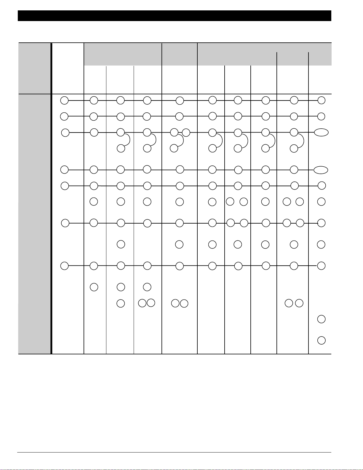
KEEPRITE
Electromechanical
Chronotherm
III
Electronic Replacement or Upgrade
®
Chronotherm
IV
Function
Common
Compressor
D
Power
1st Stage
Heat
Aux. Heat
Fan
C/O V alve
Heat
C/O V alve
Cool
System
Monitor
Existing
Terminals
T841A1712
Y594R1425
Y594G1419
Y594G1476
T8611R1000
T8611G1004
T8411R1002
T8411R1028
T8511G1021
T8511G1047
T8011R1006
T8011R1014
T8611G2002
T8611G2028
PC8900/
W8900B1002
BXXX C CCCCC
RRRR R RRRRR
Y Y Y Y1 Y1 or Y Y Y1 Y Y1
––
W
W2 W2 W2 W2 W2 W2 W2 W2 Aux.
W1 W1 W1 W1 W1 W1 W1 –
E
E
E
EE
E
E
Y1/W1
B
GGGG G GGGGG
1
O/B O/B
1
O/B O/B
1
1
– B B B B B B or
O O O O O O O or
1
O/B
1
O/B
BB or
OO or
––L– L LLLLL
Em. Heat
X
E
E
E
Multiple Aux.
Heat Loads
LED
Indication
C
2nd Stage
–
––
W3 W3 W3 – – – – – –
X2 X1 X2 X1 X2
–––– – ––––
Compressor
2nd Stage
–––– – ––––
Cool
A Configure O/B (select models) in Installer Setup.
B When W2 is not used, configure W2 cycle rate to NC.
C Terminal is for multiple auxiliary heat loads such as contactors, sequencers,
or relays.
TYPICAL THERMOSTATS AND SUBBASES — HONEYWELL MODEL NUMBER
T874R1814/Q674L1132
EEEEEE
–– –
X1 X2
–
W2
B
Y2
D Terminal X (C,B) must be connected to transformer common.
E Leave factory-installed jumper in place.
M13193
70-6627 • 74
Page 77

LENNOX
TYPICAL HP6 (ALTERNATE)
Function
Common
Compressor
D
Power
1st Stage
Heat
Auxiliary
Heat
Fan
C/O V alve
Heat
C/O V alve
Cool
Chronotherm
Electromechanical
T8611R1000
J
Y594G1419
Y594G1476
J
Existing T erminals
or or or
X2
–
VR
M
–
–R – W1 W1 W1 W1 W1 W1 W1
Y
––XX C CCCCC
I
V/VR V/VR
W1 M1
W2
YY
Y594R1425
I
RR R RRRRR
B
M Y1 Y1 Y1 or Y Y Y1 Y Y1
W2 W2 W2 W2 W2 W2 W2 Aux.
FGFGGG G GGGGG
– –– –
B B B B B or
RY1 – R O O O O O or
®
III
T8611G1004
J
T8411R1002
T8411R1028
J
Chronotherm
IV
PC8900/
W8900B1002
Y1/W1
J
–
O/B O/B
A
O/B O/B
J
T8611G2002
T8611G2028
T8511G1021
T8511G1047
T8011R1006
T8011R1014
J
AA
O/B
A
O/B
BB or
OO or
H
K
A
A
Electronic Replacement or Upgrade
System Monitor/
–– – –
F
L– L LLLLL
System Defrost
Em. Heat
Multiple Aux.
Heat Loads
LED
Indicator
2nd Stage
E –– –
EE E EEEEE
– – – – – W3
C
– – – –
– – – –
–
–– – ––––
E
E
X1 X2 X1 X2
Compressor
A Configure O/B (select models) in Installer Setup.
B Both first stage heat and cool are connected to M terminal.
C Terminal is for multiple auxiliary heat loads such as contactors, sequencers or
relays.
D Terminal X (C) must be connected to transformer common.
E Field-installed E to W2 (Aux) jumper required.
F LED is energized when terminal is powered.
TYPICAL THERMOSTATS AND SUBBASES — HONEYWELL MODEL NUMBER
T872G1026/Q672E1019 T872G1067/Q672E1142 (P-8-11222)
T872R1040/Q672B1202 (P-8-11221) T874R1024/Q674B1160
T874G1014/Q674E1148 (24F5801) T874G1154/Q674E1015
T874G1022/Q674E1148 (24F5701)
GG
E
G
E
F
E
E
F
E
F
E
– –––––
–– –
G L terminal is powered continuously when thermostat is in Em. Ht. position.
H If separate Y1 and W1 terminals are required, install R8222D1014; see
page 12.
I If separate transformers are used, replace with one 75 VA transformer as
shown on page 78.
J When replacing models with one compressor terminal (M), jumper Y1 to W1.
K When W2 is not used, configure W2 cycle rate to NC.
X1 X2
–
K
W2
M13161
70-6627 • 75
Page 78

LENNOX
HP6
Electromechanical
Chronotherm
III
Electronic Replacement or Upgrade
®
Chronotherm
IV
Function
Common
Compressor
SystemMonitor/
System Defrost
A
Power
1st Stage
Heat
Auxiliary
Heat
Fan
C/O V alve
Cool
Existing
Terminals
or or
T841B1000
T874C1018
NOT
Q674B1075
AVAILABLE
T8611R1000
T8611G1004
T8411R1002
T8411R1028
T8511G1021
T8511G1047
T8011R1006
T8011R1014
T8611G2002
T8611G2028
PC8900/
W8900B1002
––– X – C C C C C C
R V VR V VR V
Y1
W1 R – W1 W1 W1 W1 W1 W1 W1
W2
GFF G G G G G G G G
–
D
or or
D
RR R R R R R R
M1
YY
E
MY1Y1 Y1YY1YY1
E
E
E
W2 W2 W2 W2 W2 W2 W2 Aux.
NOT AVAILABLE
– R O O O O O or
E
C
Y1/W1
E
E
E
–
G
BB
O/B
OO or
O/B O/B
B
X1 – – – – L L L L L L
Em. Heat
2nd Stage
Compressor
A Terminal X (C) must be connected to transformer common.
B Configure O/B (select models) in Installer Setup.
C If separate Y1 and W1 terminals are required, install R8222D1014; see
page 12.
––– – – E E E E E E
––– – – – – – – –
F
F
F
F
F
W2
D If separate transformers are used, replace with one 75 VA transformer as
shown on page 78.
E When replacing models with one compressor terminal, jumper
F Field-installed E to W2 (Aux) jumper required.
G When W2 is not used, configure W2 cycle rate to NC.
Y1
to W1.
M13162
F
G
70-6627 • 76
Page 79

IMPORTANT: Replace separate indoor/outdoor transformers with single 75 VA transformer. See diagram on page 78.
LENNOX
HP9, HP10
Function
Common
D
Indoor
Common
Outside
Power
Indoor
Power
Outside
Compressor
1st Stage
Heat
Auxiliary
Heat
Electronic Replacement or Upgrade
Chronotherm
IV
T8511G1021
T8511G1047
T8011R1006
T8011R1014
T8611G2002
T8611G2028
PC8900/
W8900B1002
Existing
Terminals
Electromechanical
T841A1712
Y594R1425
Y594G1419
Y594G1476
Chronotherm
III
T8611R1000
T8611G1004
®
T8411R1002
T8411R1028
XXXX C CCCCC
X3
VR
I
––– – ––– ––
RRR R RRR RR
V––– – –––––
Y1
MYYY1
E
––
or
W1
Y W2 W2 W2 W2 W2 W2 W2 W2 Aux.
W1 W1 W1 W1 W1 W1 W1
E
or Y Y Y1 Y Y1
E
E
E
E
Y1/W1
E
–
Fan
C/O V alve
FGGG G GGGGG
– B B B B B B or
Heat
C/O V alve
R O O O O O O or
Cool
System Monitor/
C
L L L L L L L L
J
System Defrost
Em. Heat
Thermistor
Multiple Aux.
EEEE E EEEEE
B
A––– – –––––
–W3W3W3 – ––– ––
Heat Loads
LED
Indication
A Configure O/B (select models) in Installer Setup.
B Tape off. Not used.
C R8222B1067 Relay required to operate system monitor light (emergency
heat LED) on TRADELINE replacement thermostats. See page 10.
D Terminal X (C) must be connected to transformer common.
E Do not remove factory-installed jumper.
F Optional Check LED on T8611G1004. See Fig. 26.
––
TYPICAL THERMOSTATS AND SUBBASES — HONEYWELL MODEL NUMBER (CUSTOMER PART NUMBER)
T872G1067/Q672L1029 (P-8-11222)
T872R1024/Q672L1003
T872R1040/Q672L1029 (P-8-11221)
T872R1131/Q672L1144
G
X2 X1 X2 X1 X2
AA
O/B
A
O/B
K
F
G Field-installed X2 to X jumper (provided).
H Use Aux terminal for Auxiliary heat and configure W2 cycle rate to NC.
I If separate transformers are used, replace with one 75 VA transformer, as
shown on page 78.
J LED is energized when terminal is powered.
K L terminal is powered continuously when thermostat is in Em. Ht. position.
T874C1448/Q674L12165 (24F5101/24F5901)
T874R1020/Q674L1025 (24F5401/24F6101)
T874R1178/Q674L1165 (24F5601/24F5901)
K
J
–– –
BB or
OO or
K
X1 X2
O/B O/B
A
O/B O/B
J
A
A
J
–
M13163
70-6627 • 77
Page 80

IMPORTANT:
DISCONNECT POWER SUPPLY BEFORE BEGINNING WIRING.
STEP
4
ATTACH BOTH WIRES (FORMER
VR AND V) TO REPLACEMENT
THERMOSTAT R TERMINAL
TIE FORMER OUTSIDE
STEP
TRANSFORMER COMMON
TO NEW TRANSORMER
3
COMMON
3
YELLOW
SERVICE
LIGHT
THERMOSTAT
THERMISTOR
REMOVE FORMER
STEP
OUTSIDE
1
TRANSFORMER
TAPE OFF
XXX
INDOOR BLOWER
RELAY
COMPRESSOR
CONTACTOR
DEFROST
RELAY
REVERSING
VALVE
EMERGENCY
HEAT RELAY
HEAT RELAY
NO. 1
OUTDOOR
THERMOSTAT
DEFROST
CONTROL
RELAY
DEFROST
RELAY
TAPE
OFF
1
FORMER
V
F
M
R
E
X
Y
L
A
VR R
REPLACEMENT
THERMOSTAT/
SUBBASE
G
Y
(Y1 + W1)
O
E
X
W2
L
(X1)
X2
70-6627 • 78
HEAT RELAY
NO. 2
1
RELAY REQUIRED TO OPERATE SYSTEM MONITOR LIGHT ON TRADELINE
THERMOSTATS. TAPE OFF IF NOT DESIRED.
HEAT RELAY
NO. 1 (AUX)
EMERGENCY
HEAT RELAY
REPLACE FORMER INDOOR
STEP
TRANSFORMER WITH NEW 75VA
2
AT88A1021 OR AT175A1008
M958B
Page 81

LENNOX
HP11
IMPORTANT: Replace separate indoor/outdoor transformers with single 75 VA transformer. See diagram on page 78.
Electronic Replacement or Upgrade
Electromechanical
Chronotherm® III
Chronotherm IV
Function
Common
Power Indoor
Common Outside
Common Outside
Compressor Stage 1
Compressor Stage 2
Auxiliary Heat
D
Fan
C/O V alve
Cool
Existing
Terminals
A
T874D1165/
Q674F1022
T8611M7008
T8511M1002
T8611M2017
T8611M2025
PC8900/
W8900B1002
X X1 C C C C
G
VR
RRRRR
X– ––––
G
V
M Y1 Y Y1 Y1
G
E
G
G
G
G
Y1/W1
M2 Y2 Y2 Y2 Y2 Y2
W2
Y
W2 W3 W3 W3 Aux.
C
––
C
C
W2
C
FG GGGG
RO O
H
O/B O/B O/B
H
H
C/O V alve
–B B
Heat
System Monitor/
LX2 L L L L
B
System Defrost
Em. Heat
Thermistor
1st Stage Heat
LED Indication
A IMPORTANT: When subbase system is in AUTO position, equipment will
operate in COOL mode only (Q674F1022).
B For emergency heat indication, jumper E and X2. For auxiliary heat
indication, jumper W2 and X2. For any X2 functions, X1 must be connected to
transformer common.
C For proper operation of auxiliary heat connect Y to W3 or AUX terminal.
D Terminal must be connected to the transformer common.
E W1 to Y1 jumper required.
T872G1323/Q672L1201 T874D1033 T874D1199
T874D1207/Q674L1199 T874D1207/Q674L1389
EE EEEE
A– ––––
–W1 – – – –
– – X1 X2
TYPICAL THERMOSTATS AND SUBBASES — HONEYWELL MODEL NUMBER
H
O/B O/B O/B
J
F
F Optional LED indication activated with completed circuit on X1 and
X2 terminals.
G Replace separate indoor and outdoor transformers with one 75 VA
transformer. See page 78 for wiring diagram.
H Configure O/B (select models) in Installer Setup.
I LED is energized when terminal is powered.
J L terminal is powered continuously when thermostat is in Em. Ht. position.
I
–
H
J
X1 X2
F
H
I
–
M13156
70-6627 • 79
Page 82

LENNOX
HP16, HP19, HP21, HP22 (DIRECT REPLACEMENTS)
Function
Common
Compressor
System Monitor/
Sytem Defrost
Outdoor Stat/
A
Power
1st Stage
Heat
Auxiliary
Heat
Fan
C/O V alve
Heat
C/O V alve
Cool
G
Em. Heat
Chronotherm
Electromechanical
Existing
Terminals
T841A1555
Y594R1763
Y594G1161
XBBB C CCCCC
F
V
RR R R R R R R R R
V
MYYY
– – – – W1 W1 W1 W1 W1
YWWW
FGGG G GGGGG
––––
R O O O O O O or
G
LFFF L LLLLL
J
J
J
EX2X2X2 E EEEEE
T8611R1000
Y1
®
III
T8411R1002
T8611G1004
or
Y Y Y1 Y Y1
C
T8411R1028
C
T8511G1021
T8511G1047
T8011R1006
C
Chronotherm
T8011R1014
T8611G2002
C
IV
PC8900/
T8611G2028
C
W8900B1002
Y1/W1
–
W2 W2 W2 W2 W2 Aux.
HH
B B B or
E
E
O/B
O/B
J
BB or
H
OO or
E
O/B O/B
H
O/B O/B
J
H
H
J
Electronic Replacement or Upgrade
Outdoor
ATTT
Sensor
LED Indication
A Terminal B (C or X) must be connected to transformer common.
B Tape off. Thermostat replaces outdoor reset with improved zero droop
performance.
C Do not remove factory-installed jumper.
D Optional LED indication activated with completed circuit on X1 and X2
terminals.
E L terminal is powered continuously when thermostat is in Em. Ht. position.
T874C1448/Q674L1355 (24F5101/31F3201) T874C1448/Q674L1165 (24F5101/24F5901)
T874R1178/Q674L1355 (24F5601/31F3201) T874R1178/Q674L1165 (24F5601/24F5901)
––––
TYPICAL THERMOSTATS AND SUBBASES — HONEYWELL MODEL NUMBER (CUSTOMER PART NUMBER)
70-6627 • 80
B
D
X1 X2
F If separate transformers are used, replace with one 75 Va transformer as
shown on page 78.
G R8222B1067 Relay required to operate system monitor light (emergency
heat LED) on TRADELINE replacement thermostats. See page 11. Tape
off if LED indication is not desired.
H Configure O/B (select models) in Installer Setup.
I When W2 is not used, configure W2 cycle rate to NC.
J LED is energized when terminal is powered.
B
–– –
B
B
B
X1 X2
B
D
–
M13164
Page 83

LENNOX
HP16, HP18, HP19, HP20, HP21, HP22
Function
Common
Compressor
G
Power
1st Stage
Heat
Auxiliary
Heat
Fan
C/O V alve
Heat
C/O V alve
Cool
Electromechanical
Chronotherm
Existing
Terminals
or
X
X2
or
V
M
or
or
C
I
or
VR
or
YYYY1
T841A1712
X
XXXCCCCCC
Y594R1425
RRRRRRRRRR
– – W1 W1 W1 W1 W1 W1 W1
or W or
Y
F
R
W2 W2 W2 W2 W2 W2 W2 W2 W2 Aux.
or
GGGGGGGGGG
or
–
BBBBBBB or
or
OOOOOOO or
H
Y594G1419
Y594G1476
H
T8611R1000
Y1
®
III
T8411R1002
T8611G1004
or
Y Y Y1 Y Y1
H
T8411R1028
H
T8511G1021
T8511G1047
T8011R1006
T8011R1014
H
AA
O/B
A
O/B
Electronic Replacement or Upgrade
Chronotherm
IV
T8611G2002
T8611G2028
H
BB or
OO or
PC8900/
W8900B1002
Y1/W1
H
–
O/B O/B
A
O/B O/B
J
A
A
System Monitor/
F
C
L L L LLLLL
L
System Defrost
F
EM. Heat
Multiple Aux.
Heat Loads
E
Thermistor
LED Indication
A Configure O/B (select models) in Installer Setup.
B Optional LED indication activated with completed circuit on X1 and
X2 terminals.
C Not on HP18 or HP20.
D Tape off. Not used.
E Terminal is for multiple second stage loads such as contactors, sequencers,
or relays.
F R8222B1067 Relay required to operate system monitor light (emergency
heat LED) on TRADELINE replacement thermostats, see page 10. Tape off
if LED indication is not desired.
TYPICAL THERMOSTATS AND SUBBASES — HONEYWELL MODEL NUMBER (CUSTOMER PART NUMBER)
E EEEEEEEEE
W3 W3 W3 W3
D
A –––––––––
or
X1
X2
T874C1448/Q674L1355(24F5101/31F3201) T874C1448/Q674L1165(24F5101/24F5901)
T874G1014/Q674F1113(24F5801/24F6201) T874G1154/Q674F1105
T874R1178/Q674L1355(24F5601/31F3201) T874R1178/Q674L1165(24F5601/24F5901)
T8141A1089 T8611G1053 (27H3001)
–
X2 X1 X2 X1 X2
M
K
B
B
G Terminal X (X2 or C) must be connected to transformer common.
H Do not remove factory-installed jumper.
I If separate transformers are used, replace with one 75 VA transformer as
shown on page 78.
J When W2 is not used, configure W2 cycle rate to NC.
K If multiple auxiliary heat loads are used, connect to W2 (Aux W8900B)
terminal.
L LED is energized when terminal is powered.
M L terminal is powered continuously in Emergency Heat Position.
M
K
–– –
L
K
M
K
L
K
B
X1 X2
L
K
–
M13165
70-6627 • 81
Page 84

LUXAIRE (MONCRIEF/FRASER JOHNSTON)
Function
Common
Compressor
D
Power
1st Stage
Heat
Auxiliary
Heat
Fan
C/O V alve
Heat
C/O V alve
Cool
Chronotherm
Electromechanical
Existing
Terminals
T841A1712
Y594R1425
B or X X X X C C C C C C
RRRR R RR R RR
B
YYYY1
– – W1 W1 W1 W1 W1 W1 W1
or
W
W2 W2 W2 W2 W2 W2 W2 W2 W2 Aux.
GGGG G GG G GG
–BBB
O O O O O O O or
E
Y594G1419
Y594G1476
E
T8611R1000
Y1
®
III
T8411R1002
T8611G1004
or
Y Y Y1 Y Y1
E
T8411R1028
E
T8511G1021
T8511G1047
B B B or
T8011R1006
T8011R1014
E
AA
O/B
A
O/B
E
BB or
OO or
Chronotherm
IV
T8611G2002
T8611G2028
E
O/B O/B
A
O/B O/B
PC8900/
W8900B1002
Y1/W1
–
J
A
A
Electronic Replacement or Upgrade
System Monitor/
––L– L LLL LL
System Defrost
EM. Heat
Multiple Aux.
Heat Loads
LED Indication
2nd Stage
X or E E E E E E E E E E
C
–
–
W3 W3 W3
–
X2
F
X1
X2
I
–––– – –– – –W2
Compressor
A Configure O/B (select models) in Installer Setup.
B Both first stage heat and cool are connected to Y terminal.
C Terminal is for multiple second stage loads such as contactors, sequencers,
or relays.
D Terminal X (C or B) must be connected to transformer common.
E Do not remove factory-installed jumper.
F Field-installed X2 to X jumper (provided).
G
X1
H
X2
G If multiple auxiliary heat loads are used, connect to W2 (Aux W8900B)
terminal.
H Optional CHECK LED. Connect X1 to switching device; jumper X2 to C.
I Optional LED indication activated with completed circuit on X1 and
X2 terminals.
J When W2 is not used, configure W2 cycle rate to NC.
G
–– –
G
G
X1 X2
G
I
G
–
J
M13166
70-6627 • 82
Page 85

MAGIC CHEF
“PB” SERIES EQUIPMENT
Function
Common
Power
1st Stage
Cool
1st Stage
Heat
2nd Stage
Heat
Fan
C/O V alve
Heat
Chronotherm
Electromechanical
Existing
Terminals
B
CXCCCCCC
R
Y1 Y1 Y1
W1 W1 W1 W1 W1 W1 W1 W1
W2 W2 W2 W2 W2 W2 W2 W2 W2
GGGGGGGGG
–BB
NOT
AVAILABLE
NOT AV AILABLE
A
T874C1018/
Q674B1034
Rc
C
Y594G1419
Y594G1476
RRRRRRR
®
III
T8611R1000
Y1
CC
B B B or
T8411R1002
T8411R1028
YY1 Y Y1
C
T8511G1021
T8511G1047
C
O/B
Chronotherm
T8011R1006
T8011R1014
C
BB or
T8611G2002
Electronic Replacement or Upgrade
IV
PC8900/
T8611G2028
C
O/B O/B
W8900B1002
F
Y1/W1
–
C/O V alve
OOOOOO or
Cool
System Monitor/
X1 X1 L L L L L L
E
System Defrost
EM. Heat
2nd Stage
E–EEEEEEE
–
Y2 – – – – – – Y2
Cool
Power Heat
A IMPORTANT: No provision for emergency heat, system monitor (compressor
fault), or auxiliary heat LEDs.
B Terminal C (X) must be connected to transformer common.
C Remove Y1 (Y) to W1 (W) jumper.
–Rh–
O/B
4
4
E
––––
D L terminal is powered continuously when thermostat is in Em. Ht. position.
E LED is energized when terminal is powered.
F If separate Y1 and W1 terminals required, install R8222D1014; see
page 12.
OO or
4
O/B O/B
E
–
M13167
E
–
70-6627 • 83
Page 86

MAGIC CHEF
“PE” SERIES EQUIPMENT
Function
Common
Compressor
F
Power
1st Stage
Heat
Aux. Heat
Fan
C/O V alve
Heat
C/O V alve
Cool
Electronic Replacement or Upgrade
Chronotherm
IV
T8511G1021
T8511G1047
T8011R1006
T8011R1014
T8611G2002
T8611G2028
PC8900/
W8900B1002
Existing
Terminals
Electromechanical
T841A1712
Y594R1425
Y594G1419
Y594G1476
Chronotherm
III
T8611R1000
T8611G1004
®
T8411R1002
T8411R1028
CXXX C CCCCC
RRRR R RRRRR
B
YYYY1
–
W
–
W1 W1 W1 W1 W1 W1 W1 –
W2 W2 W2 W2 W2 W2 W2 W2 Aux.
Y1
or
GGG
Y
YY1 Y Y1
G
G
G
G
Y1/W1
L
GGGG G GGGGG
–BBB
B B B or
O O O O O O O or
O/B
O/B
BB or
OO or
AA
O/B O/B
AA
O/B O/B
A
A
System Monitor/
System Defrost
4
EM. Heat
Multiple Aux.
Heat Loads
LED
Indication
C
E
X1 L L L L L L L
EEEE E EEEEE
–
–
W3 W3 W3
–
I
X2 X1 X2 X1 X2
K
2nd Stage
Compressor
A Configure O/B (select models) in Installer Setup.
B Both first stage heat and cool are connected to Y terminal.
C Terminal is for multiple second stage loads such as contactors, sequencers,
or relays.
D If provided on original equipment.
E Relay (typically R8222B1067) required if outdoor section has reset shunt
relay and malfunction light indication is desired on thermostat. See page 11.
F Terminal C (X) must be connected to transformer common.
G Do not remove factory-installed jumper.
–––– – ––––W2
N
J
H
H Optional CHECK LED on T8611G1004. Connect X1 to X1 on control
terminal; jumper X2 to R.
I Field-installed X2 to X jumper (provided).
J If multiple auxiliary heat loads are used, connect to W2 (Aux W8900B)
terminal.
K Optional LED indication activated with completed circuit on X1 and
X2 terminals.
L When W2 is not used, configure W2 cycle rate to NC.
M LED is energized when terminal is powered.
N L terminal is powered continuously in Emergency Heat Position.
N
J
–– –
M
J
N
J
M
J
K
X1 X2
M
J
–
L
M13168
70-6627 • 84
Page 87

MAMMOTH
Function
Common
Power Reset
F
Power
1st Stage
Comp.
2nd Stage
Comp.
1st Stage
Heat
Aux. Heat
Chronotherm
Electromechanical
Existing
Terminals
T841A1712
Y594R1425
C or X X X X C C C C C C
R or R1 R R R R R R R R R
R2 – – – – – – – – –
Y1 or YY Y Y1
B
Y2 – – – – – – – – – Y2
––
D
W1 W1 W1 W1 W1 W1 W1 –
W2 W2 W2 W2 W2 W2 W2 W2 W2 Aux.
Y594G1419
Y594G1476
GG
T8611R1000
Y1
G
®
III
T8611G1004
or
Y
Chronotherm
IV
T8411R1002
T8411R1028
YY1 Y Y1
T8511G1021
T8511G1047
GG
T8011R1006
T8011R1014
G
T8611G2002
T8611G2028
G
PC8900/
W8900B1002
Y1/W1
Electronic Replacement or Upgrade
J
Fan
C/O V alve
GGGG G GGGGG
BBBB
B B B or
O/B
BB or
Heat
C/O V alve
O O O O O O O or
O/B
OO or
Cool
D
System Monitor/
E
X or L L L L L L L L
L
M
M
L
M
System Defrost
E
EM. Heat
Multiple Aux.
Heat Loads
LED
Indication
Filter
C
–EEE E EEEEE
–
–
W3 W3 W3 – – – – – –
–
I
X2 X1 X2 X1 X2
K
H
–– –
X1 X2
F––– – –––––
2nd Stage
Compressor
A Configure O/B (select models) in Installer Setup.
B Both first stage heat and cool are connected to Y terminal.
C Terminal is for multiple auxiliary heat loads such as contactors, sequencers,
or relays.
D If provided on original equipment.
E Relay (typically R8222B1067) required if outdoor section has reset shunt
relay and malfunction light indication is desired on thermostat. See page 11.
F Terminal X (C) must be connected to transformer common.
T834C2135 T841B1042 T874G1659/Q674C1330 T874H1096/Q674C1330 T874Y1005/Q674E1353
–––– – ––––
G Do not remove factory-installed jumper.
H Optional CHECK LED on T8611G1004. See Fig. 26.
I Field-installed X2 to X jumper (provided).
J When W2 is not used, configure W2 cycle rate to NC.
K Optional LED indication activated with completed circuit on X1 and
X2 terminals.
L LED is energized when terminal is powered.
M L terminal is powered continuously in Emergency Heat Position.
TYPICAL THERMOSTATS AND SUBBASES — HONEYWELL MODEL NUMBER
AA
O/B O/B
AA
O/B O/B
L
K
–
W2
M13169
A
A
L
J
70-6627 • 85
Page 88

MAMMOTH
USED WITH A STANDARD HEAT PUMP THERMOSTAT
Function
Common
Compressor
D
Power
1st Stage
Heat
Aux. Heat
Fan
C/O V alve
Heat
C/O V alve
Cool
Chronotherm
Electromechanical
Existing
Terminals
T841A1712
Y594R1425
CXXX C CCCCC
RRRR R RRRRR
H
Y Y Y Y1 Y1 or Y Y Y1 Y Y1
––
C
W2 W2 W2 W2 W2 W2 W2 W2 W2 Aux.
W1 W1 W1 W1 W1 W1 W1 –
GGGG G GGGGG
B B B B B B B or
O O O O O O O or
E
Y594G1419
Y594G1476
E
T8611R1000
®
III
T8611G1004
E
T8411R1002
T8411R1028
T8511G1021
T8511G1047
EE
1
O/B
1
O/B
Chronotherm
T8011R1006
T8011R1014
E
BB or
OO or
IV
T8611G2002
T8611G2028
E
1
O/B O/B
1
O/B O/B
PC8900/
W8900B1002
Y1/W1
J
1
1
Electronic Replacement or Upgrade
System Monitor/
LL LLLLLL
L
System Defrost
Em. Heat
–
EEE
Multiple Aux.
Heat Loads B
LED
Indication
2nd Stage
–
––
W3 W3 W3
G
X2 X1 X2 X1 X2
K
–––– – ––––
Compressor
2nd Stage
–––– – ––––
Cool
A Configure O/B (select models) in Installer Setup.
B Terminal is for multiple auxiliary heat loads such as contactors, sequencers,
or relays.
C If provided on original equipment.
D Terminal must be connected to the transformer common.
E Do not remove factory-installed jumper.
F Optional CHECK LED on T8611G1004. Connect L to X1; jumper X2 to C.
G Field-installed X2 to X jumper.
M
MM
L
L
L
EEEEEE
I
F
I
–– –
I
I
I
K
X1 X2
I
–
W2
J
Y2
H Both first stage heat and cool are connected to Y terminal.
I If multiple auxiliary heat loads are used, connect to W2 (Aux W8900B)
terminal.
J When W2 is not used, configure W2 cycle rate to NC.
K Optional LED indication activated with completed circuit on X1 and
X2 terminals.
L LED is energized when terminal is powered.
M L terminal is powered continuously when thermostat is in Em. Ht. position.
M13194
70-6627 • 86
TYPICAL THERMOSTATS AND SUBBASES — HONEYWELL MODEL NUMBER (CUSTOMER PART NUMBER)
T834C2135 (71116901) T841B1042 (71117001)
Page 89

MAMMOTH
USED WITH A NIGHT SETBACK THERMOSTAT
Function
Common
Night Setback
Compressor
F
Power
Power
1st Stage
Heat
Aux. Heat
Fan
C/O V alve
Heat
C/O V alve
Cool
Chronotherm
Electromechanical
Existing
Terminals
J
CXXX C CCCCC
D
R1 R R R R R R R R R
T841A1712
Y594R1425
R2 – – – – – – – – –
Y Y Y Y1 Y1 or Y Y Y1 Y Y1
G
––
–
W2 W2 W2 W2 W2 W2 W2 W2 Aux.
W1 W1 W1 W1 W1 W1 W1 –
GGGG G GGGGG
B B B B B B B or
O O O O O O O or
Y594G1419
Y594G1476
G
T8611R1000
®
III
T8611G1004
G
T8411R1002
T8411R1028
T8511G1021
T8511G1047
GG
1
O/B
1
O/B
Chronotherm
T8011R1006
T8011R1014
G
BB or
OO or
IV
T8611G2002
T8611G2028
G
1
O/B O/B
1
O/B O/B
PC8900/
W8900B1002
Y1/W1
B
1
1
Electronic Replacement or Upgrade
System Monitor/
XL LLLLLL
L
System Defrost
Em. Heat
–
EEE
Multiple Aux.
Heat Loads C
LED
Indication
2nd Stage
–
––
W3 W3 W3
I
X2 X1 X2 X1 X2
E
–––– – ––––
Compressor
2nd Stage
–––– – ––––
Cool
A Configure O/B (select models) in Installer Setup.
B When W2 is not used, configure W2 cycle rate to NC.
C Terminal is for multiple auxiliary heat loads such as contactors, sequencers,
or relays.
D Disconnect external timimg device from circuit before wiring replacement
thermostat.
E Optional LED indication activated with completed circuit on X1 and
X2 terminals.
F Terminal must be connected to the transformer common.
M
MM
L
L
L
EEEEEE
K
H
K
–– –
K
K
K
E
X1 X2
K
–
B
W2
Y2
G Do not remove factory-installed jumper.
H Optional CHECK LED on T8611G1004. See Fig. 26.
I Field-installed X2 to X (C) jumper.
J C terminal is located on terminal strip, not on subbase.
K If multiple auxiliary heat loads are used, connect to W2 (Aux W8900B)
terminal.
L LED is energized when terminal is powered.
M L terminal is powered continuously when thermostat is in Em. Ht. position.
M13195
TYPICAL THERMOSTATS AND SUBBASES — HONEYWELL MODEL NUMBER (CUSTOMER PART NUMBER)
T874G1378/Q674C1124 T874G1659/Q674C1330 (71115201) T874H1096/Q674C1330 (71115201)
70-6627 • 87
Page 90

MARTIN INDUSTRIES
Function
Common
Compressor
E
Power
1st Stage
Heat
Aux. Heat
Fan
C/O V alve
Heat
C/O V alve
Cool
Chronotherm
Electromechanical
Existing
Terminals
T841A1712
Y594R1425
XXXX C CCCCC
RRRR R RRRRR
B
Y Y Y Y1 Y1 or Y Y Y1 Y Y1
––
W1 W1 W1 W1 W1 W1 W1 –
W2 W2 W2 W2 W2 W2 W2 W2 W2 Aux.
GGGG G GGGGG
B B B B B B B or
O O O O O O O or
F
Y594G1419
Y594G1476
F
T8611R1000
®
III
T8611G1004
F
T8411R1002
T8411R1028
T8511G1021
T8511G1047
FF
1
O/B
1
O/B
Chronotherm
T8011R1006
T8011R1014
F
BB or
OO or
IV
T8611G2002
T8611G2028
F
1
O/B O/B
1
O/B O/B
PC8900/
W8900B1002
Y1/W1
G
1
1
Electronic Replacement or Upgrade
System Monitor/
LL LLLLLL
I
System Defrost
Em. Heat
Multiple Aux.
Heat Loads
LED
Indication
2nd Stage
C
E
EEE
W3 W3 W3 W3
––X2X1
X2
D
–––– – ––––
Compressor
2nd Stage
–––– – ––––
Cool
A Configure O/B (select models) in Installer Setup.
B Both first stage heat and cool are connected to Y terminal.
C Terminal is for multiple auxiliary heat loads such as contactors, sequencers,
or relays.
D LED indication with completed circuit on X1 and X2 terminals.
E Terminal must be connected to the transformer common.
J
JJ
I
I
I
EEEEEE
H
X1
X2
H
D
–– –
H
H
H
X1 X2
D
H
–
W2
G
Y2
F Do not remove factory-installed jumper.
G When W2 is not used, configure W2 cycle rate to NC.
H If multiple auxiliary heat loads are used, connect to W2 (Aux W8900B)
terminal.
I LED is energized when terminal is powered.
J L terminal is powered continuously when thermostat is in Em. Ht. position.
M13196
T841A1183 T841A1522 T841A1548 (24015808)
70-6627 • 88
TYPICAL THERMOSTATS AND SUBBASES — HONEYWELL MODEL NUMBER (CUSTOMER PART NUMBER)
Page 91

PHILLIPS ENERGY
Function
Common
Compressor
D
Power
1st Stage
Heat
Aux. Heat
Fan
C/O V alve
Heat
C/O V alve
Cool
Chronotherm
Electromechanical
Existing
Terminals
T841A1712
Y594R1425
CXXX C CCCCC
RRRR R RRRRR
H
Y1 Y Y Y1 Y1 or Y Y Y1 Y Y1
F
W1
–
W1 W1 W1 W1 W1 W1 W1 –
W2 W2 W2 W2 W2 W2 W2 W2 W2 Aux.
GGGG G GGGGG
B B B B B B B or
O O O O O O O or
F
Y594G1419
Y594G1476
F
T8611R1000
®
III
T8611G1004
F
T8411R1002
T8411R1028
T8511G1021
T8511G1047
FF
1
O/B
1
O/B
Chronotherm
T8011R1006
T8011R1014
F
BB or
OO or
IV
T8611G2002
T8611G2028
F
1
O/B O/B
1
O/B O/B
PC8900/
W8900B1002
Y1/W1
B
1
1
Electronic Replacement or Upgrade
System Monitor/
LL LLLLLL
H
System Defrost
Em. Heat
E
EEE
Multiple Aux.
Heat Loads C
LED
Indication
2nd Stage
–
X2
W3 W3 W3
–
X2 X1 X2 X1 X2
JJG
–––– – ––––
Compressor
2nd Stage
–––– – ––––
Cool
A Configure O/B (select models) in Installer Setup.
B When W2 is not used, configure W2 cycle rate to NC.
C Terminal is for multiple auxiliary heat loads such as contactors, sequencers,
or relays.
D Terminal must be connected to the transformer common.
E If multiple auxiliary heat loads are used, connect to W2 (Aux W8900B)
terminal.
I
HHHII
EEEEEE
E
E
E
–– –
E
E
X1 X2
J
E
–
W2
B
Y2
F Do not remove factory-installed jumper.
G Field-installed X2 to X jumper.
H LED is energized when terminal is powered.
I L terminal is powered continuously when thermostat is in Em. Ht. position.
J Optional LED indication activated with completed circuit on X1 and
X2 terminals.
M13197
TYPICAL THERMOSTATS AND SUBBASES — HONEYWELL MODEL NUMBER
T8611R1174
70-6627 • 89
Page 92

RHEEM/RUUD
COOLING CHANGEOVER (PRE 11/85) (PCA, PNA, PNB TYPICAL)
Function
Common
Compressor
D
Power
1st Stage
Heat
Aux. Heat
Fan
C/O V alve
Heat
C/O V alve
Cool
Electronic Replacement or Upgrade
Chronotherm
IV
T8511G1021
T8511G1047
T8011R1006
T8011R1014
T8611G2002
T8611G2028
PC8900/
W8900B1002
Existing
Terminals
Electromechanical
T841A1712
Y594R1425
Y594G1419
Y594G1476
Chronotherm
III
T8611R1000
T8611G1004
®
T8411R1002
T8411R1028
XXXX C CCCCC
RRRR R RRRRR
or
Y1
Y Y Y Y1 Y1 or Y Y Y1 Y Y1
F
W1
C
W2 W2 W2 W2 W2 W2 W2 W2 W2 Aux.
–
W1 W1 W1 W1 W1 W1 W1 –
F
F
FF
F
Y1/W1
F
2
GGGG G GGGGG
1
O/B O/B
1
O/B O/B
1
1
B B B B B B B or
O O O O O O O or
1
O/B
1
O/B
BB or
OO or
System
LL LLLLLL
I
Monitor
Em. Heat
E
EEE
Multiple Aux.
Heat Loads
LED
Indication
C
2nd Stage
W3 W3 W3 W3
––
X2 X1 X2 X1 X2
–––– – ––––
Compressor
2nd Stage
–––– – ––––
Cool
A Configure O/B (select models) in Installer Setup.
B When W2 is not used, configure W2 cycle rate to NC.
C Terminal is for multiple auxiliary heat loads such as contactors, sequencers,
or relays.
D Terminal must be connected to the transformer common.
E If multiple auxiliary heat loads are used, connect to W2 (Aux W8900B)
terminal.
J
IIIJJ
EEEEEE
E
GGH
E
–– –
E
E
E
X1 X2
G
E
–
W2
2
Y2
F Do not remove factory-installed jumper.
G Optional LED indication with completed circuit on X1 and X2 terminals.
H Field-installed X2 to X (C) jumper.
I LED is energized when terminal is powered.
J L terminal is powered continuously when thermostat is in Em. Ht. position.
M13198
70-6627 • 90
Page 93

RHEEM/RUUD
PCB, PFA, PGB, PGA HEATING CHANGEOVER (AFTER 11/85) RPCB, RPFA
Function
Common
Compressor
D
Power
1st Stage
Heat
Aux. Heat
Fan
C/O V alve
Heat
C/O V alve
Cool
Chronotherm
Electromechanical
Existing
Terminals
T841A1308
Y594R1425
XXXX C CCCCC
RRRR R RRRRR
Y Y Y1 Y1 Y1 or Y Y Y1 Y Y1
– – W1 W1 W1 W1 W1 W1 W1 –
W2 W2 W2 W2 W2 W2 W2 W2 W2 Aux.
GGGG G GGGGG
B B B B B B B or
O O O – O O O or
E
Y594G1419
Y594G1476
E
J
T8611R1000
®
III
T8611G1004
E
J
T8411R1002
T8411R1028
T8511G1021
T8511G1047
EE
A
O/B
A
O/B
Chronotherm
T8011R1006
T8011R1014
E
BB or
OO or
IV
T8611G2002
T8611G2028
E
A
O/B O/B
A
O/B O/B
PC8900/
W8900B1002
Y1/W1
B
A
A
Electronic Replacement or Upgrade
System
L
L
II
LX1 L LL L L L
I
Monitor
Em. Heat
Multiple Aux.
EE
–W3W3
H
EE
Heat Loads C
LED
Indication
2nd Stage
––
X2 X2 X1 X2
–––– – ––––
Compressor
2nd Stage
–––
–
Cool
A Configure O/B (select models) in Installer Setup.
B When W2 is not used, configure W2 cycle rate to NC.
C Terminal is for multiple auxiliary heat loads such as contactors, sequencers,
or relays.
D Terminal must be connected to the transformer common.
E Do not remove factory-installed jumper.
J
IJIJI
EEEEEE
H
FGG
H
H
–– –
HH
X1 X2
–––––
F Optional Check LED on T8611G1004. See Fig. 26.
G Field-installed X2 to X (C) jumper.
H If multiple auxiliary heat loads are used, connect to W2 (Aux W8900B)
terminal.
I LED is energized when terminal is powered.
J L terminal is powered continuously when thermostat is in Em. Ht. position.
H
–
B
W2
Y2
M13206
70-6627 • 91
Page 94

SECO
TA2000, TA2040, TA2010 TA2050
Function
Common
Compressor
D
Power
1st Stage
Heat
Aux. Heat
Fan
C/O V alve
Heat
C/O V alve
Cool
Chronotherm
Electromechanical
Existing
Terminals
T841A1712
Y594R1425
XXXX C CCCCC
RRRR R RRRRR
Y Y Y Y1 Y1 or Y Y Y1 Y Y1
––
W2
WWW
W1 W1 W1 W1 W1 W1 W1 –
GGGG G GGGGG
B B B B B B B or
O O O O O O O or
F
Y594G1419
Y594G1476
F
T8611R1000
®
III
T8611G1004
T8411R1002
T8411R1028
T8511G1021
T8511G1047
T8011R1006
Chronotherm
T8011R1014
IV
T8611G2002
T8611G2028
PC8900/
W8900B1002
Y1/W1
F
FF
F
F
W2 W2 W2 W2 W2 Aux.
O/B
A
O/B
BB or
OO or
O/B O/B
A
O/B O/B
B
AAA
A
Electronic Replacement or Upgrade
System Monitor/
J
LL LLLLLL
I
System Defrost
Em. Heat
Multiple Aux.
Heat Lads
LED
Indication
2nd Stage
J
EEEE E EEEEE
F
W3 W3 W3 W3
C
––
–––– – ––––W2
H
X2 X1 X2 X1 X2
FF
G
Compressor
2nd Stage
–––– – ––––
Cool
A Configure O/B (select models) in Installer Setup.
B When W2 is not used, configure W2 cycle rate to NC.
C Terminal is for multiple auxiliary heat loads such as contactors, sequencers,
or relays.
D Terminal must be connected to the transformer common.
E If multiple auxiliary heat loads are used, connect to W2 (Aux W8900B)
terminal.
K
G
–– –
X1 X2
G
IIIKK
EEEEEE
–
B
Y2
F Do not remove factory-installed jumper.
G Optional LED indication with completed circuit on X1 and X2 terminals.
H Field-installed X2 to X (C) jumper.
I LED is energized when terminal is powered.
J E and L terminals are not available on TA2010 or TA2050.
K L terminal is powered continuously when thermostat is in Em. Ht. position.
M13171
70-6627 • 92
Page 95

SECO
TA2060
Function
Common
Compressor
A
Power
1st Stage
Heat
Aux. Heat
Fan
C/O V alve
Heat
C/O V alve
Cool
Electronic Replacement or Upgrade
Chronotherm
IV
T8511G1021
T8511G1047
T8011R1006
T8011R1014
T8611G2002
T8611G2028
PC8900/
W8900B1002
Existing
Terminals
Electromechanical
T841A1555
Y594R1763
Chronotherm
Y594G1161
®
III
T8611R1000
T8611G1004
T8411R1002
T8411R1028
XBBB C CCCCC
RRRR R RRRRR
Y Y Y Y Y1 or Y Y Y1 Y Y1
––––
W2
WWW
C
W1 W1 W1 W1 W1 –
W2 W2 W2 W2 W2 Aux.
CC
C
C
Y1/W1
G
GGGG G GGGGG
EEE
– – – – B B B or
O O O O O O O or
O/B
E
O/B
BB or
OO or
O/B O/B
E
O/B O/B
E
System Monitor/
LFFF L LLLLL
HH
H
System Defrost
Outdoor
W3
F
TTT
FF
Thermistor/
Sensor
Em. Heat
LED
Indication
2nd Stage
E
––––
X2 X2 X2
X1 X2
–––– – ––––
Compressor
2nd Stage
–––– – ––––
Cool
A Terminal must be connected to the transformer common.
B Tape off. Thermostat replaces outdoor reset with improved zero droop
performance.
C Do not remove factory-installed jumper.
D Optional LED indication with completed circuit on X1 and X2 terminals.
I
HHHII
BBBBBB
EEEEEE
D
–– –
X1 X2
4
–
W2
G
Y2
E Configure O/B (select models) in Installer Setup.
F Replace existing thermistor with Honeywell C815A1005.
G When W2 is not used, configure W2 cycle rate to NC.
H LED is energized when terminal is powered.
I L terminal is powered continuously when thermostat is in Em. Ht. position.
M13199
70-6627 • 93
Page 96

SUN MANUFACTURING
Function
Common
Compressor
C
Power
1st Stage
Heat
Aux. Heat
Fan
C/O V alve
Heat
C/O V alve
Cool
Electronic Replacement or Upgrade
Chronotherm
IV
T8511G1021
T8511G1047
T8011R1006
T8011R1014
T8611G2002
T8611G2028
PC8900/
W8900B1002
Existing
Terminals
Electromechanical
T841A1712
Y594R1425
Y594G1419
Y594G1476
Chronotherm
III
T8611R1000
T8611G1004
®
T8411R1002
T8411R1028
XXXX C CCCCC
RRRR R RRRRR
Y Y Y Y1 Y1 or Y Y Y1 Y Y1
E
E
EE
E
––
W1 W1 W1 W1 W1 W1 W1 –
E
E
Y1/W1
B
W1 W2 W2 W2 W2 W2 W2 W2 W2 Aux.
GGGG G GGGGG
A
O/B O/B
A
O/B O/B
A
A
B B B B B B B or
O O O O O O O or
A
O/B
A
O/B
BB or
OO or
System Monitor/
LLX1LLLLLL
I
I
System Defrost
Em. Heat
Multiple Aux.
Heat Loads
LED
Indication
2nd Stage
E
W3 W3 W3 W3
D
––
–––– – ––––
EEE
F
F
G
X2 X2 X1 X2
F
G
Compressor
2nd Stage
–––– – ––––
Cool
A Configure O/B (select models) in Installer Setup.
B When W2 is not used, configure W2 cycle rate to NC.
C Terminal must be connected to the transformer common.
D Terminal is for multiple auxiliary heat loads such as contactors, sequencers,
or relays.
E Do not remove factory-installed jumper.
J
JJ
I
I
I
EEEEEE
H
F
H
H
–– –
H
H
X1 X2
H
–
W2
B
Y2
F Optional LED indication with completed circuit on X1 and X2 terminals.
G Field-installed X2 to X (C) jumper.
H If multiple auxiliary heat loads are used, connect to W2 (Aux W8900B)
terminal.
I LED is energized when terminal is powered.
J L terminal is powered continuously when thermostat is in Em. Ht. position.
M13200
70-6627 • 94
TYPICAL THERMOSTATS AND SUBBASES — HONEYWELL MODEL NUMBER (CUSTOMER PART NUMBER)
T841A1399 (HPL1404)
Page 97

SQUARE D/SUN DIAL
Function
Common
Compressor
System Monitor/
System Defrost
D
Power
1st Stage
Heat
Aux. Heat
Fan
C/O V alve
Heat
C/O V alve
Cool
Chronotherm
Electromechanical
Existing
Terminals
T841A1712
Y594R1425
C or X X X X C C C C C C
RRRR R RRRRR
Y Y Y Y1 Y1 or Y Y Y1 Y Y1
––
W1 W1 W1 W1 W1 W1 W1 –
W2 W2 W2 W2 W2 W2 W2 W2 W2 Aux.
GGGG G GGGGG
B B B B B B B or
O O O O O O O or
LL LLLLLL
Y594G1419
Y594G1476
F
8GG8G88
F
T8611R1000/
®
III
T8611G1004
F
T8411R1002
T8411R1028
T8511G1021
T8511G1047
FF
A
O/B
A
O/B
Chronotherm
T8011R1006
T8011R1014
F
BB or
OO or
IV
T8611G2002
T8611G2028
F
A
O/B O/B
A
O/B O/B
PC8900/
W8900B1002
Y1/W1
B
A
A
Electronic Replacement or Upgrade
Em. Heat
Multiple Aux.
Heat Loads
LED
Indication
2nd Stage
C
K
or
E
EEE
W3 W3 W3 W3
––X2X1
X2
–––– – ––––
Compressor
2nd Stage
–––– – ––––
Cool
A Configure O/B (select models) in Installer Setup.
B When W2 is not used, configure W2 cycle rate to NC.
C Terminal is for multiple auxiliary heat loads such as contactors, sequencers,
or relays.
D Terminal must be connected to the transformer common.
TYPICAL THERMOSTATS AND SUBBASES — HONEYWELL MODEL NUMBER (CUSTOMER PART NUMBER)
T841A1357
T841A1365 (121000012)
EEEEEE
E
X1
X2
E
E
–– –
E
E
X1 X2
E
–
W2
B
Y2
E If multiple auxiliary heat loads are used, connect to W2 (Aux W8900B)
terminal.
F Do not remove factory-installed jumper.
G L terminal is powered continuously when thermostat is in Em. Ht. position.
8 LED is energized when terminal is powered.
M13201
70-6627 • 95
Page 98

SQUARE D/SUN DIAL
Function
Common
Compressor
B
Power
1st Stage
Heat
Aux. Heat
Fan
C/O V alve
Heat
Electronic Replacement or Upgrade
III
A
®
T8411R1002
T8411R1028
T8511G1021
T8511G1047
T8011R1006
AA
O/B
Chronotherm
T8011R1014
A
BB or
IV
T8611G2002
T8611G2028
A
O/B O/B
PC8900/
W8900B1002
C
Y1/W1
E
Chronotherm
Electromechanical
Existing
Terminals
NOT
AVAILABLE
X or X1 or C X1 C C C C C C
RRRRRRRR
Y or Y1 Y1 Y1 or Y Y Y1 Y Y1
W1 W1 W1 W1 W1 W1 W1 –
W2 W2 W2 W2 W2 W2 W2 Aux.
GGGGGGGG
B B B B B or
NOT
AVAILABLE
NOT AVAILABLE
T874C1018/
NOT AVAILABLE
Q674F1022
A
T8611R1000
C/O V alve
O O O O O or
Cool
System Monitor/
L
X2
F
System Defrost
Em. Heat
LED
Indication
2nd Stage
or
K
E
E
X2 X2 X1 X2
–––––––
Compressor
2nd Stage
Y2 Y2 Y2
Cool
A Remove factory-installed Y1 (Y) to W1 jumper.
B Terminal must be connected to the transformer common.
C If separate Y1 and W1 terminals are required, install R8222D1014; see page 12.
D Optional LED indication activated with completed circuit on X1 and
X2 terminals.
O/B
G
LLLLLL
GF
F
OO or
G
O/B O/B
F
EEEEEE
D
–
E
W2
E When W2 is not used, configure W2 cycle rate to NC.
F LED is energized when terminal is powered.
G L terminal is powered continuously when thermostat is in Em. Ht. position.
M13202
70-6627 • 96
TYPICAL THERMOSTATS AND SUBBASES — HONEYWELL MODEL NUMBER (CUSTOMER PART NUMBER)
T872C1525/Q672F1182 (HCD-2/HCB-1)
T874C1224/Q674F1071 (63600-002-09/63600-002-11)
Page 99

TRANE/AMERICAN STANDARD
DIRECT TRADE REPLACEMENTS
Function
Common
Compressor
A
Power
1st Stage
Heat
Aux. Heat
Fan
C/O V alve
Heat
C/O V alve
Cool
Chronotherm
Electromechanical
Existing
Terminals
T841A1555
Y594R1763
Y594G1161
BBBB C CCC CC
RRRR R RRR RR
Y Y Y Y Y1 or Y Y Y1 Y Y1
––––
W or
W1
WWW
GGGG G GGG GG
–
––– B BB or
O O O O O O O or
T8611R1000
W1 W1 W1 W1 W1 –
®
III
T8611G1004
T8411R1002
T8411R1028
T8511G1021
T8511G1047
T8011R1006
T8011R1014
Chronotherm
IV
T8611G2002
T8611G2028
PC8900/
W8900B1002
Y1/W1
C
C
C
C
C
W2 W2 W2 W2 W2 Aux.
E
O/B O/B
E
O/B O/B
O/B
E
O/B
E
BB or
OO or
Electronic Replacement or Upgrade
F
E
E
System Monitor/
F F F F L L L L L L
G
G
G
System Defrost
Outdoor
T
or
A
T
TT
Sensor C
Outdoor Stat
LED
Indication
2nd Stage
X2 X2 X2 X2
––––
–––– – ––– –
Compressor
2nd Stage
–––– – ––– –
Cool
A Terminal must be connected to the transformer common.
B Tape off. Thermostat replaces outdoor reset with improved zero droop
performance.
C Do not remove factory-installed jumper.
D Optional LED indication with completed circuit on X1 and X2 terminals.
TYPICAL THERMOSTATS AND SUBBASES — HONEYWELL MODEL NUMBER (CUSTOMER PART NUMBER)
T841A1407 (ASYSTAT652)
T841A1530 (ASYSTAT652A)
T872G1059/Q672J1039
T872R1057/Q672L1037
T874G1204/Q674J1043
T874G1675/Q674J1142 (ASYSTAT650/WY28X0250)
T874R1053/Q674L1140
T874R1426/Q674L1496 (BAYSTAT339/WY28X0112)
T874R1657/Q674L1611 (ASYSTAT651/WY28X235)
H
B
H
B
G
B
H
B
G
B
G
B
EEEEEE
X1 X2
D
–– –
X1 X2
D
–
W2
F
Y2
E Configure O/B (select models) in Installer Setup.
F When W2 is not used, configure W2 cycle rate to NC.
G LED is energized when terminal is powered.
H L terminal is powered continuously when thermostat is in Em. Ht. position.
M13225
T874R1939 (ASYSTAT-651A)/Q674L1801 (THT1225)
T8141A1014
T8141A1071
T8300A1128/Q6300A1101 (BAY28X194/BAY28X195)
T8611G1038 (THT-0603)
T8611G1111 (TAYSTAT501)
T8611R1091
T8611R1109 (THT-0602)
T8611R1117 (ASYSTAT700)
70-6627 • 97
Page 100

TRANE/AMERICAN STANDARD
Function
Common
Compressor
A
Power
1st Stage
Heat
Aux. Heat
Fan
C/O V alve
Heat
C/O V alve
Cool
Chronotherm
Electromechanical
Existing
Terminals
T841A1555
Y594R1763
Y594G1161
CBBB C CCC CC
RRRR R RRR RR
Y or Y1 Y Y Y Y1 or Y Y Y1 Y Y1
W1
W2
–––
WWW
GGGG G GGG GG
B
––– B BB or
O O O O O O O or
T8611R1000
W1 W1 W1 W1 W1 –
®
III
T8611G1004
T8411R1002
T8411R1028
T8511G1021
T8511G1047
T8011R1006
Chronotherm
T8011R1014
IV
T8611G2002
T8611G2028
PC8900/
W8900B1002
Y1/W1
C
C
C
C
C
W2 W2 W2 W2 W2 Aux.
E
O/B O/B
E
O/B O/B
O/B
E
O/B
E
BB or
OO or
Electronic Replacement or Upgrade
F
E
E
System Monitor/
L F F F L L L L L L
G
G
System Defrost
Outdoor Stat
LED
Indication
2nd Stage
E
or
X1
X2
–––– – ––– –
X2 X2 X2
–––
Compressor
2nd Stage
–––– – ––– –
Cool
A Terminal must be connected to the transformer common.
B Optional LED indication activated with completed circuit on X1 and
X2 terminals.
C Do not remove factory-installed jumper.
D Optional LED on T8611G1004. See Fig. 26.
G
H
H
G
H
G
G
EEEEEE
B
X1 X2
–
W2
F
X1 X2
D
–– –
Y2
E Configure O/B (select models) in Installer Setup.
F When W2 is not used, configure W2 cycle rate to NC.
G LED is energized when terminal is powered.
H L terminal is powered continuously when thermostat is in Em. Ht. position.
M13226
70-6627 • 98
 Loading...