

Page 1
T8400C1099, T8401C1031
Electronic Thermostats
The T8400 and T8401 Thermostats provide single-stage,
non-programmable temperature control for 24V heatingcooling systems with manual changeover from heat to
cool. Heating cycle rate is selectable at 1, 3, 4, 5, 6, 9, or
12 cph. Cooling cycle rate is fixed at 3 cph. Temperature
indication can be set for °F or °C.
The T8400 Thermostat is powered through the heating/
cooling system controls. The T8401 requires a common
wire for operation. Batteries are not required because
setpoints are held permanently by non-volatile memory.
The T8400 and T8401 models include a thermostat,
wallplate (for wiring and mounting thermostat) and
owner’s guide.
MERCURY NOTICE
If this control is replacing a control that contains
mercury in a sealed tube, do not place your old
control in the trash.
Contact your local waste management authority
for instructions regarding recycling and the
proper disposal of an old control containing
mercury in a sealed tube.
INSTALLATION
When Installing this Product…
1. Read these instructions carefully. Failure to follow
them could damage the product or cause a hazardous condition.
2. Check the ratings given in the instructions and on
the product to make sure the product is suitable for
your application.
3. Installer must be a trained, experienced service
technician.
4. After installation is complete, check out product
operation as provided in these instructions.
INSTALLATION INSTRUCTIONS
CAUTION
Electrical Shock or Equipment Damage
Hazard.
Can shock individuals or short equipment
circuitry.
Disconnect power supply before installation.
Location
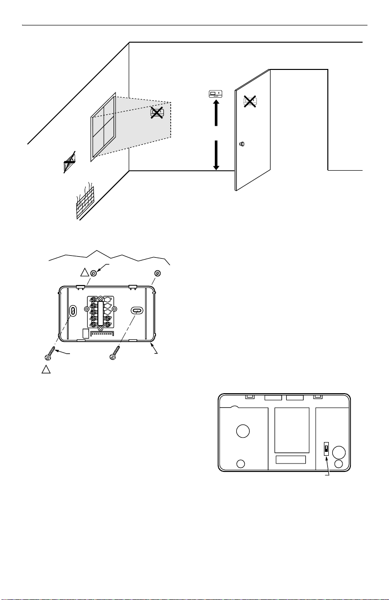
Install the thermostat about 5 ft (1.5m) above the floor in
an area with good air circulation at average temperature.
See Fig. 1. Do not install the thermostat where it can be
affected by:
— drafts or dead spots behind doors and in corners.
— hot or cold air from ducts.
— radiant heat from the sun or appliances.
— concealed pipes and chimneys.
— unheated (uncooled) areas such as an outside wall
behind the thermostat.
This thermostat is a precision instrument and was
carefully adjusted at the factory. Handle it carefully.
Mounting Wallplate to Wall
IMPORTANT
Level only for appearance. The thermostat functions normally even when not level.
Mount the T8400 and T8401 with the screws provided
(see Fig. 2) as follows:
1. Place the wallplate at the desired location on the
wall.
2. Pull the thermostat wire through the entrance hole
on the wallplate.
3. Fasten the wallplate to the wall using the anchors
and screws provided.
4. After wiring the wallplate, plug the hole to prevent
drafts from affecting the thermostat; see Wiring
section.
® U.S. Registered Trademark
Copyright © 2002 Honeywell • • All Rights Reserved
69-1484-2
Page 2
T8400C1099, T8401C1031 ELECTRONIC THERMOSTATS
M12202A
M12580
FAN OPERATION (FUEL) SWITCH
NO
WALL
MOUNTING
SCREWS (2)
1
WHEN USING WALL ANCHORS, DRILL 3/16 INCH
HOLES FOR DRYWALL, 7/32 INCH HOLES FOR
PLASTER OR WOOD.
WALL
ANCHORS (2)
1
WALLPLATE
Fig. 2. Mounting wallplate to wall.
YES
NO
5 FEET
[1.5 METERS]
Fig. 1. Typical location of thermostat.
Wiring
IMPORTANT
Use an 18-gauge maximum wire to wire the
T8400 and T8401 Thermostats.
All wiring must comply with local electrical codes and
ordinances. Disconnect the power supply to prevent
electrical shock or equipment damage.
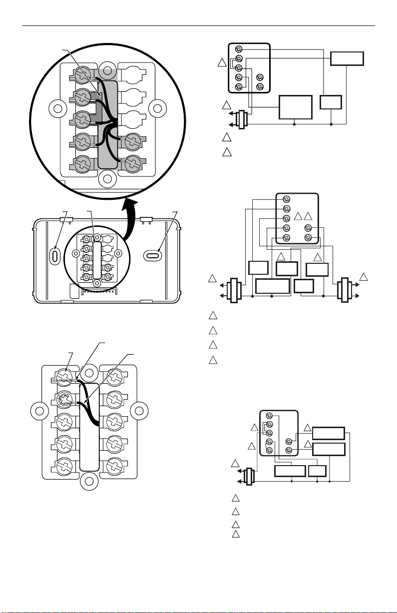
NOTE: To ensure proper mounting of thermostat,
restrict all wiring to the shaded area. See Fig. 4.
The shape of the terminals permits insertion of straight or
wraparound wiring connections; either method is
acceptable. See Fig. 5.
Refer to Fig. 6 through 10 for typical wiring hookups.
NO
M11338
Setting Fan Operation (Fuel) Switch
The fan operation (fuel) switch is preset at the factory in
the F position. See Fig. 3. This is the correct setting for
most systems. If this system is an electric heat system,
set the switch to the E position. The E setting allows the
fan to turn on immediately with the heating or cooling
equipment in a system where the G terminal is
connected.
69-1484-2 2
E
F
Fig. 3. Fan operation (fuel) switch.
Page 3
T8400C1099, T8401C1031 ELECTRONIC THERMOSTATS
)
A
T)
L
(
L
L
(
L
0
KEEP WIRING IN
SHADED AREA
G
Rc
R
W
Y
MOUNTING
SCREW HOLE
WIRING ENTRANCE
HOLE
Fig. 4. Restrict wiring to shaded area
(T8400C1099 shown).
FOR STRAIGHT INSERTION
TERMINAL
SCREW
STRIP 5/16 IN. (8 MM)
G
Rc
B
O
MOUNTING
SCREW HOLE
M16432
FOR WRAPAROUND
STRIP 7/16 IN. (11 MM
G
Rc
2
R
W
Y
1
L1
(HOT)
L2
POWER SUPPLY. PROVIDE DISCONNECT MEANS AND
1
OVERLOAD PROTECTION AS REQUIRED.
FACTORY INSTALLED JUMPER.
2
Fig. 6. Typical hookup of T8400C1099 in heat-cool
1
1
HOT)
2
COOLING
TRANSFORMER
1
POWER SUPPLY. PROVIDE DISCONNECT MEANS AND OVERLOAD
PROTECTION AS REQUIRED.
2
REMOVE RC TO R JUMPER WHEN INSTALLED ON A TWO TRANSFORMER
SYSTEM.
3
CAN BE USED FOR CHANGEOVER VALVE ON SINGLE-STAGE HEAT
PUMP SYSTEMS.
4
POWER TO R TERMINAL IS REQUIRED WHEN THE SYSTEM SWITCH IS IN
THE OFF POSITION.
Fig. 7. Typical hookup of T8400C1099 in heat-cool
B
O
HEATING
PRIMARY
24V
CONTROL
system with single transformer.
G
Rc
R
2
W
Y
3
FAN
COOL
RELAY
DAMPER
COMPRESSOR
CONTACTOR
HEAT
RELAY
system with two transformers.
4
B
O
HEAT
DAMPER
3
FAN
RELAY
COOLING
CONTACTOR
M13275
HEATING
TRANSFORMER
M12562
1
L1
(HO
L2
R
W
B
Y
Fig. 5. Wiring connections
(T8400C1099 shown).
O
M13274
HOT)
TRANSFORMER
Fig. 8. Typical hookup of T8400C1099 in single-stage
G
Rc
3
R
W
4
Y
1
1
2
1
POWER SUPPLY. PROVIDE DISCONNECT MEANS
AND OVERLOAD PROTECTION AS REQUIRED.
CAN BE USED FOR CHANGEOVER VALVE ON
2
SINGLE-STAGE HEAT PUMP SYSTEMS.
3
FACTORY INSTALLED JUMPER.
4
FIELD INSTALLED JUMPER.
COMPRESSOR
24V
2
B
2
O
heat pump systems.
HEAT
CHANGEOVER
COOL
CHANGEOVER
FAN
RELAY
M2088
3 69-1484-2
Page 4

T8400C1099, T8401C1031 ELECTRONIC THERMOSTATS
L
(
L
1
L
(
L
2
CASE TO LATCH.
G
C
R
W
Y
1
1
HOT)
TRANSFORMER
24V
2
1
POWER SUPPLY. PROVIDE DISCONNECT MEANS
AND OVERLOAD PROTECTION AS REQUIRED.
Fig. 9. Typical hookup of T8401C1031 in heat-cool
G
C
R
W
Y
1
1
HOT)
2
TRANSFORMER
1
POWER SUPPLY. PROVIDE DISCONNECT MEANS
AND OVERLOAD PROTECTION AS REQUIRED.
CAN BE USED FOR CHANGEOVER VALVE ON
2
SINGLE-STAGE HEAT PUMP SYSTEMS.
3
FIELD INSTALLED JUMPER.
Fig. 10. Typical hookup of T8401C1031 in single-
COMPRESSOR
24V
stage heat pump system.
HEAT
RELAY
system.
3
B
O
COOL
RELAY
B
O
FAN
RELAY
2
HEAT
CHANGEOVER
2
COOL
CHANGEOVER
FAN
RELAY
M2088
M2088
Mounting Thermostat to Wallplate
1. Engage the tabs at the top of the thermostat and
wallplate.
2. Swing down the thermostat and press the lower
edge of the thermostat onto the wallplate to latch.
See Fig. 11.
DASHED LINES INDICATE TABS
ON BACK OF THERMOSTAT
FAN
Auto On
SYSTEM
Cool Off Heat
A
ENGAGE T ABS AT TOP OF THERMOSTA T
WITH SLOTS ON MOUNTING PLATE.
FAN
Auto On
SYSTEM
Cool Off Heat
PRESS LOWER EDGE OF
B
M14677
Fig. 11. Mounting thermostat wallplate.
OPERATION
Setting FAN and SYSTEM Switches
Fan and system settings are controlled manually by
using the switches located at the bottom of the
thermostat case. See Fig. 12.
69-1484-2 4
FAN Switch
Fan switch settings are:
On: The fan runs continuously. Use for improved air
circulation and air quality.
Auto: Normal setting for most homes. In cooling, the
fan starts and stops with the cooling equipment. In
heating, the fan is controlled directly by the heating
equipment and may start a few minutes after the
heating equipment turns on (on most systems).
When using an electric heat thermostat, the fan
starts and stops with the heating equipment.
Slide the FAN switch in the bottom left corner of the
thermostat to select the desired fan setting.
Page 5

T8400C1099, T8401C1031 ELECTRONIC THERMOSTATS
S
9
0
1
2
3
4
5
6
SYSTEM Switch
System switch settings control thermostat operation as
follows:
Cool: The thermostat controls the cooling system.
Off: Both heating and cooling are off.
Heat: The thermostat controls the heating system.
Slide the SYSTEM switch in the bottom right corner of
the thermostat to select the desired system setting.
TEMPERATURE DISPLAY
INCREASE SETTING
DECREASE SETTING
FAN
Auto On
SYSTEM
FAN SWITCH
Fig. 12. Digital display and system
switches (FAN and SYSTEM).
Cool Off Heat
SYSTEM SWITCH
M14678
Set Temperature Setpoint
NOTE: Temperature setpoint range is 40° to 99°F (5° to
37°C).
The temperature setpoint and the room temperature are
shown separately on the digital display. The ▼ indicator
points to Set when the temperature setpoint is displayed
and to Room when the room temperature is displayed.
.
INDICATOR
ROOM TEMPERATURE
Room
et
SETPOINT TEMPERATURE
To set temperature setpoint:
1. Select Heat or Cool by sliding the SYSTEM switch
in the lower right corner of the thermostat to the
desired mode. See Fig. 12.
2. To display the temperature setpoint on the digital
display, press either the ▲ or ▼ key once. The tem-
perature setpoint is displayed for approximately
five seconds as the indicator points to Set and
flashes.
M1468
M1467
3. To increase the temperature setpoint press the ▲
key. Each press changes the setpoint one degree;
press and hold to change the setpoint several
degrees.
M1468
4. To decrease the temperature setpoint press the ▼
key. Each press changes the setpoint one degree;
press and hold to change the setpoint several
degrees.
M1468
Setting °F/°C Indication and Heat Cycle Rate
NOTE: To save changes to the °F/°C indication, the
heat cycle rate and the C3/C1 temperature
control, tap the ▲ key until exiting the installer
setup.
To set the °F/°C indication, the heat cycle rate and the
C3/C1 temperature control:
1. If the temperature is displayed in °F, set the temperature setpoint to 52°F. If the room temperature
is displayed in °C, set the temperature setpoint to
11° C.
M1468
OPTIONAL SYSTEM CHECKOUT
When in steps 2 and 3 only, the
turn heat or cool outputs on and off. Change the
SYSTEM switch setting to test heat or cool outputs. No
action takes place If the system switch is in the Off
position.
Examples: System setting at HEAT: If heat is on, the ▼
key turns it off; if heat is off, ▼ turns it on.
System setting at COOL: If cool is on, ▼ key
turns it off; if cool is off, ▼ turns it on.
2. Press the ▲▼ keys simultaneously for more than
one second to light all segments on display and to
enter installer setup mode. When the keys are
released, a two-digit software revision code is displayed.
▼
key can be used to
M1468
M1468
M1468
5 69-1484-2
Page 6

T8400C1099, T8401C1031 ELECTRONIC THERMOSTATS
7
8
9
0
A
0
NOTE: In installer setup mode only, each press of the
▲ key momentarily displays 01. Each press of
the ▼ key momentarily displays 02. When the
keys are released, these two-digit codes are no
longer displayed.
3. Press the ▲ key. Factory information is displayed.
A typical example is shown, but information displayed varies by model. This information is for factory use only.
M1468
4. Press the ▲ key again to display °C or °F.
M1468
5. Press the ▼ key to change the °C or °F indication.
M1468
6. Press the ▲ key to display the heat cycle rate of 1,
3, 4, 5, 6, 9, or 12. To change the heat cycle rate,
press the ▼ key to scroll between 1, 3, 4, 5, 6, 9, or
12. Stop scrolling when the desired rate is displayed. See Table 1 for the cycle rate options and
the corresponding system equipment.
M1469
7. Press the ▲ key to display heating/cooling temper-
ature control default..
M18419
8. Press the ▼ key again to change heating/cooling
temperature control to C1 or C3.
C1 = Standard heating/cooling temperature
control.
C3 = Aggressive heating/cooling temperature
control (can cause room temperature to
9. Press the ▲ key again. Factory information (varies
overshoot the setpoint).
by model) is shown.
M1842
Table 1. Heating Cycle Rates.
System Cycles Per Hour
Steam, gravity 1
Hydronic heat, condensing gas
a
furnace
3
Gas or oil forced air 6
Electric heat 9
Special applications
a
High efficiency furnace.
b
Refer to equipment manufacturer’s instructions.
10. Press the ▲ key to save all changes, exit installer
setup mode and return to normal operation.
NOTE: After exiting installer setup mode, slide the
System switch to the desired position and
change the setpoint to the desired room
temperature.
b
4, 5, 12
CHECKOUT
Heating
1. Slide the SYSTEM switch to Heat and the FAN
switch to Auto.
2. Press and hold the ▲ key to raise the temperature
setting several degrees above the room temperature. After approximately ten seconds, the heating
equipment should start. In conventional systems,
the system turns on the fan through the use of a
time delay relay or through a limit control. When
using an electric heat thermostat, the fan starts
immediately.
3. Press the ▼ key to lower the temperature setting
below the room temperature. Heating equipment
should stop.
Cooling
CAUTION
Low Temperature Hazard.
Operating at too low of an outdoor
temperature may cause compressor damage.
Do not operate cooling if outdoor temperature is
below 50°F (10°C). Refer to manufacturer’s
recommendations.
• For compressor protection, during power
interruption and on initial startup, the T8400
and T8401 Thermostats go into a five-minute
delay. During this delay, the cooling icon (a
snowflake ❄) flashes.
1. Slide the SYSTEM switch to Cool and the FAN
switch to Auto.
2. Press the ▼ key to lower the temperature setting
several degrees below the room temperature. After
approximately five minutes, the cooling equipment
should start. The fan starts and stops with the cooling equipment.
69-1484-2 6
Page 7

T8400C1099, T8401C1031 ELECTRONIC THERMOSTATS
3. Press the ▲ key to raise the temperature setting
above the room temperature. Cooling system
should shut down.
NOTE: To bypass the five-minute delay, see the
Optional System Checkout section.
Fan
1. Slide the SYSTEM switch to Off and the FAN
switch to On. The fan should run continuously.
2. Slide the FAN switch to Auto. In heating, the fan is
controlled directly by the heating equipment and
may start a few minutes after the heating equipment turns on (on most systems). When using an
electric heat thermostat, the fan starts and stops
with the heating equipment. In cooling, the fan
starts and stops with the cooling equipment.
Be sure all equipment responds correctly to the
thermostat.
7 69-1484-2
Page 8

T8400C1099, T8401C1031 ELECTRONIC THERMOSTATS
Automation and Control Solutions
Honeywell Honeywell Limited-Honeywell Limitée
1985 Douglas Drive North 35 Dynamic Drive
Golden Valley, MN 55422 Scarborough, Ontario
M1V 4Z9
69-1484-2 G.H. Rev. 11-02 Printed in Mexico www.honeywell.com/yourhome
 Loading...