

Page 1
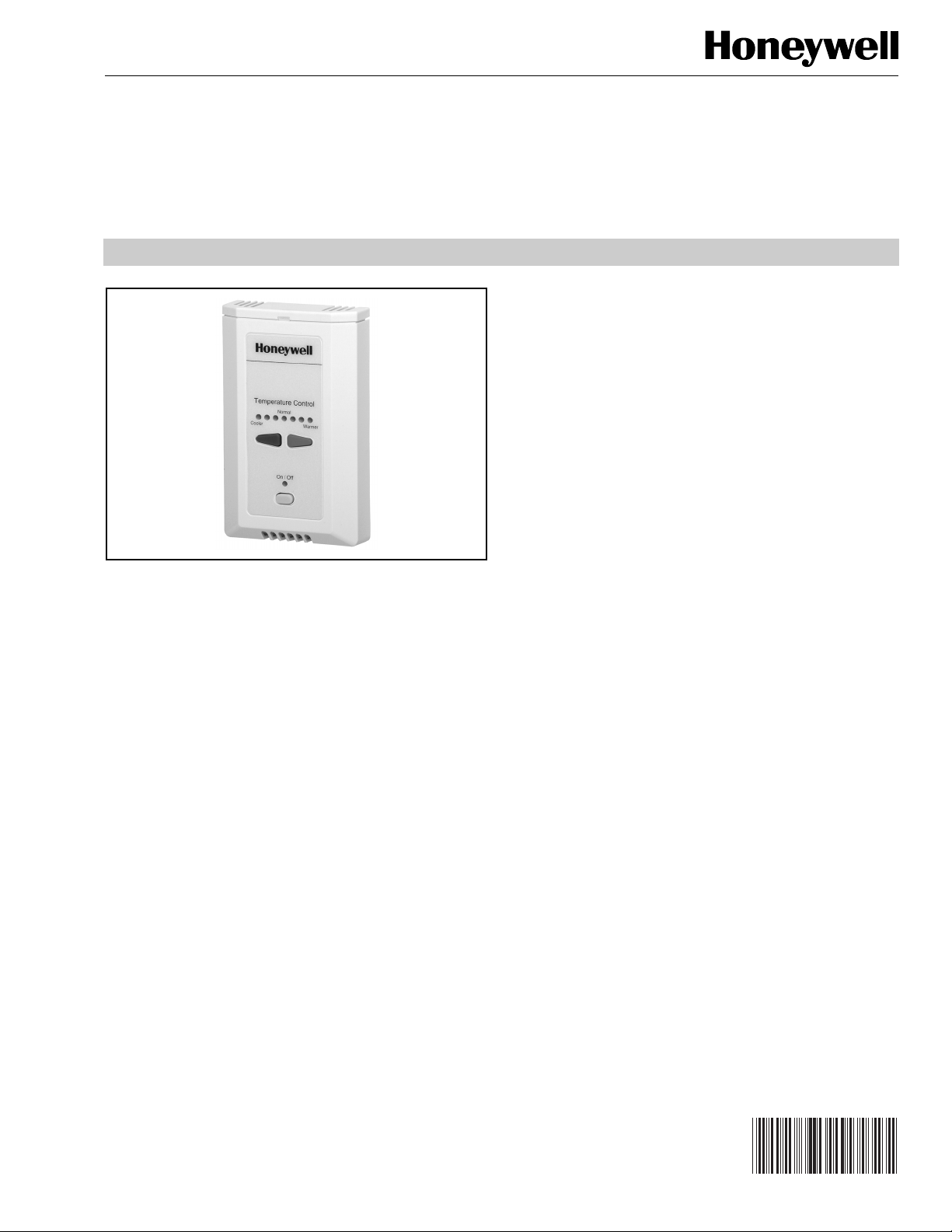
Remote Temperature Sensor
GENERAL
The T7771A Remote Temperature Sensors are direct wired
wall modules for use with the Honeywell T7350 Commercial
Programmable Thermostat. The T7771A has a space
temperature sensor, LED pushbutton setpoint adjustment, and
override with LED.
T7771A
PRODUCT DATA
FEATURES
• Pushbutton setpoint adjustment with LED indicators.
• Occupied/unoccupied override (bypass) with LED.
ONWORKS® bus jack.
•L
• Operating range 45 to 99°F (7 to 37°C).
IMPORTANT
• The T7771 compatibility with the T7350 only applies
to T7350 models with date code 0423 or later.
• To ensure the purchase of a compatible T7350, order
either:
— Y7355B1002 (consisting of: T7350B Thermostat,
T7771A and C7041B Sensors).
— Y7355D1008 (consisting of: T7350D Thermostat,
T7771A, C7041B Sensors).
SPECIFICATIONS
Construction: Two-piece construction, cover and internally
wired subbase. Field wiring 14 to 22 AWG (2.0 to 0.34
sq. mm) connects to a terminal block in the subbase. Wall
module is activated by plugging into prewired subbase.
Mounting Options:
The T7771 can be mounted on a standard two by four inch
junction box or on a 60 mm diameter junction box.
Dimensions (H/W/D):
5-1/16 x 3-1/8 x 1 in. (128 x 80 x 25 mm).
Setpoint Adjustment:
The setpoint offset allows for ±3°F from the programmed
T7350 setpoint.
Environmental Ratings:
Operating Temperature: 45° to 99°F (7° to 37°C).
Shipping Temperature: -40° to 150°F (-40° to 65°C).
® U.S. Registered Trademark
© 2004 Honeywell International Inc.
All Rights Reserved
Relative Humidity: 5% to 95% noncondensing.
Temperature Sensor Operating Range:
45 to 99°F (10 to 37°C).
Temperature Sensor Accuracy
T7771A 20K Ohm Nonlinearized Sensor:
All T7771 models are furnished with a 20K Ohm nonlinear
NTC temperature sensor that follows a specific
temperature-resistance curve. See Fig. 1.
Sensor accuracy at 77°F is ±0.36°F (±0.2°C)
See form 63-7074 for detailed nominal temperature resistance
output in table form.
NOTE: In addition, a jumper allows for 10K Ohm output to
accommodate using multiple sensors for temperature
averaging applications with the T7350 Commercial
Thermostat. See the Wiring section for details.
63-2617
Page 2

T7771A REMOTE TEMPERATURE SENSOR
80K
70K
60K
50K
40K
30K
RESISTANCE (OHMS)
20K
10K
20K OHM AT
o
77
F (25oC)
STEP
T
7771A
1
Temperature Control
Norm
Cooler
al
Warmer
O
n/Off
40 50 60 70
30
0
10
80
20
TEMPERATURE (DEGREES)
90
30
100
110
40
M5874A
o
F
o
C
Fig. 1. Temperature vs. resistance for nonlinear sensor.
Communications:
Includes a L
ONMARK® bus communications port. If needed,
the jack plug must be removed in the field, and terminals 1
and 2 wired according to the installation instructions to minimize installation errors due to miswiring.
The recommended wire size for the LONMARK® bus is
Level IV, 22 AWG (0.34 sq.mm) plenum or non-plenum
rated, nonshielded, twisted pair, solid conductor wire.
Wall Module Bypass Override/LED Operation
When the T7771 override button is pushed, the T7350 setting
changes to Temporary Occupied. If pressed again, the T7350
setting changes back to Occupied. The override button has no
effect when the T7350 programmed setting is already
Occupied.
BEFORE INSTALLATION
Cover Disassembly
One locking mechanism is used on the wall module cover.
After installation, to disassemble the cover and the subbase
see Fig. 2.
M22172
STEP
2
Fig. 2. Cover disassembly.
CAUTION
Erratic System Operation Hazard.
Failure to follow proper wiring practices can
introduce disruptive electrical interference (noise).
Keep wiring at least one foot away from large inductive
loads such as motors line starters, lighting ballasts,
and large power distribution panels.
Shielded cable is required in installations where these
guidelines cannot be met.
Ground shield only to grounded controller case.
IMPORTANT
— Wall module wiring can be sized from 14 to 22 AWG
— The maximum length of wire from a device to a wall
— Twisted pair wire is recommended for wire runs longer than
— The cover for the wall module is packed separately from
See Fig. 3 to release/replace the subbase terminal block.
All wiring must comply with local electrical codes
and ordinances or as specified on installation
wiring diagrams.
(2.0 to 0.34 sq mm) depending on the application.
module is 1000 ft (305m).
100 ft (30.5m).
the subbase for ease of installation.
ORDERING INFORMATION
When purchasing replacement and modernization products from your TRADELINE® wholesaler or distributor, refer to the
TRADELINE® Catalog or price sheets for complete ordering number.
If you have additional questions, need further information, or would like to comment on our products or services, please write or
phone:
1. Your local Honeywell Automation and Control Products Sales Office (check white pages of your phone directory).
2. Honeywell Customer Care
1885 Douglas Drive North
Minneapolis, Minnesota 55422-4386
In Canada—Honeywell Limited/Honeywell Limitée, 35 Dynamic Drive, Scarborough, Ontario M1V 4Z9.
International Sales and Service Offices in all principal cities of the world. Manufacturing in Australia, Canada, Finland, France,
Germany, Japan, Mexico, Netherlands, Spain, Taiwan, United Kingdom, U.S.A.
63-2617 2
Page 3

PRESS SHADED AREA
OF TAB WITH THUMB TO
RELEASE TERMINAL BLOCK
FOR EASIER WIRING
M17988
Fig. 3. Releasing/replacing terminal block.
INSTALLATION
CAUTION
Equipment Damage Hazard.
Electrostatic discharge can short equipment
circuitry.
Ensure that you are properly grounded before
handling the unit.
Touch only the plastic cover, casing, and buttons.
Mount the T7771A Wall Module on an inside wall
approximately 54 in. (1372 mm) from the floor (or in the
specified location) to allow exposure to the average zone
temperature. Do not mount the wall module on an outside
wall, on a wall containing waterpipes or near air ducts. Avoid
locations that are exposed to discharge air from registers or
radiation from lights, appliances, or the sun.
The wall module can be mounted on a wall, on a standard
utility conduit box using No. 6 (3.5 mm) screws or on a 60 mm
wall outlet box (see Fig. 5). When mounting directly on a wall,
use the type of screws appropriate for the wall material.
NOTE: See Fig. 4 for subbase mounting dimensions.
T7771A REMOTE TEMPERATURE SENSOR
STANDARD UTILITY
CONDUIT BOX
SUBBASE
NO. 6 SCREW
FRONT COVER
Temperature C
ontrol
Normal
Cooler
Warm
er
On/Off
Temperature C
Cool
er
ontrol
Normal
Warm
er
On/Off
3.5 mm SCREW
FRONT COVER
60 mm WALL
OUTLET BOX
SUBBASE
Fig. 5. Mounting wall modules on standard utility
conduit box or 60 mm wall outlet box.
Wiring
Attach the wires from the device sensor terminals to the
appropriate wall module terminals. See Fig. 6.
CAUTION
Improper Electrical Contact Hazard.
Screw type terminal blocks are designed to accept
no more than one 14 AWG (2.5 sq mm) conductor.
Connect multiple wires that are 14 AWG (2.5 sq mm)
with a wire nut. Include a pigtail with this wire group
and attach the pigtail to the individual terminal block.
M22173
KNOCKOUTS FOR
EUROPEAN APPLICATIONS
5-1/16
(128)
15/16
(23)
M22174
Temperature Control
Normal
Cooler Warmer
On/Off
2-3/8 (60)
3-3/16 (80)
2-3/8
(60)
STANDARD
UTILITY
CONDUIT
BOX (2 X 4)
MOUNTING
HOLES
Fig. 4. T7771A Subbase dimensions in in. (mm).
Wire the terminal blocks as follows:
1. For single wires, strip 3/16 in. (5 mm); for multiple wires
going into one terminal, strip 1/2 in. (13 mm) insulation
from the conductor.
2. If two or more wires are being inserted into one
terminal, twist the wires together before inserting.
NOTE: When two or more wires are being inserted
into one terminal, be sure to twist them
together. Deviation from this rule can result
in improper electrical contact. See Fig. 9.
3. Insert the wire in the required terminal location and
tighten the screw to complete the termination.
4. Verify wall module wiring with Fig. 6.
NOTE: Wire the E-Bus using Level IV 22 AWG (0.34 sq mm)
plenum or non-plenum rated, unshielded, twisted
pair, solid conductor wire.
3 63-2617
Page 4

T7771A REMOTE TEMPERATURE SENSOR
Averaging Multiple Sensors
The default position for the J2 jumper is 20K ohms. When
using a single sensor, leave the jumper in this position.
For temperature averaging using a T7350 Commercial
Thermostat and multiple sensors, use the following
guidelines:
— Only one T7771 can be used.
— For the second sensor, use a T7770A3002 (which has a
10K ohm output).
— Wire the two sensors in series.
20K OHM OUTPUT
J2
SETPT
STATUS
BYPASS
GND
SENSOR
E-BUS
E-BUS
123456789
Fig. 6. Wiring diagram for T7771A Wall Modules.
T7350 SUBBASE
T4 T3
T7770A3002
T7771A
10K OHM OUTPUT
J2
M22175
10K OHM
OUTPUT
T7350 SUBBASE
T4 T3
T3
T7771A
T4
T7770A1006
T4
T3
J2
T3
20K OHM
OUTPUT
J2
T7770A1006
T4
T7770A1006
T4 T3
11APPROPRIATE T7771A JUMPER POSITION
FOR FOUR SENSOR TEMPERATURE AVERAGING.
Fig. 8. Temperature averaging with four sensors.
1.
1/2
(13)
STRIP 1/2 IN.
(13 MM) FROM
WIRES TO BE
ATTACHED AT
ONE TERMINAL.
CONTROLLER OR
WALL MODULE
E-BUS CONNECTOR
TERMINALS
M22281
T3
T4
11APPROPRIATE T7771A JUMPER POSITION
FOR TWO SENSOR TEMPERATURE AVERAGING.
Fig. 7. Temperature averaging with two sensors.
T3
T4
2.
TWIST WIRES
J2
J2
M22280
Fig. 9. Attaching two wires at wall module terminals.
TOGETHER
WITH PLIERS
(A MINIMUM OF
THREE TURNS).
When all wiring is complete, attach the cover of the T7771A
Wall Module by reversing step 2 of Fig. 2.
Automation and Control Solutions ACS Control Products
Honeywell International Inc. Honeywell Limited-Honeywell Limitée Honeywell AG
1985 Douglas Drive North 35 Dynamic Drive Böblinger Straße 17
Golden Valley, MN 55422 Scarborough, Ontario D-71101 Schönaich
M1V 4Z9 Phone (49-7041) 637-01
Fax (49-7041) 637-493
3.
CUT TWISTED END OF WIRES TO
3/16 IN. (5 MM) BEFORE INSERTING
INTO TERMINAL AND TIGHTENING
SCREW. THEN PULL ON EACH WIRE
IN ALL TERMINALS TO CHECK FOR
GOOD MECHANICAL CONNECTION.
M11413
63-2617 B.B. 6-04 www.honeywell.com
 Loading...