

Honeywell T775U2006, T775U2016 Installation Instructions Manual
INSTALLATION INSTRUCTIONS
62-0255-05
E4436
T775U Series 2000 Electronic
Stand-Alone Controller
PRODUCT DESCRIPTION
The T775 electronic stand-alone controllers are the next
generation of universal controls capable of remote
sensing of temperature, humidity, pressure, etc. and
providing switched and proportional outputs to various
types of loads. A built-in time clock is standard.
The T775U controller allows a wide range of sensors to
be configured. Humidity, pressure, temperature, or any
0-5 Vdc, 0-10 Vdc, or 4-20 mA input is supported.
A Reset function is available where the Sensor B
temperature (e.g. outside temperature) is used to provide
reset control for Sensor A (e.g. humidity). For example,
as the outside temperature gets colder, the setpoint can
automatically be adjusted to prevent condensation.
IMPORTANT
The T775U is an operating control, not a limit or
safety control. If used in applications requiring
safety or limit controls, a separate safety or limit
control device is required.
Table 1. T775U Controller Configurations.
Controller
Model
a
a
The T775U includes a digital input for use with the disable or setback option.
Description Replaces
Output
Reset
SPDT
Relay
Outputs
Analog
(Mod)
Outputs
b
b
The modulating (analog) outputs may be 4-20 mA, 0-10 Vdc, 2-10 Vdc, or Series 90 selectable.
Sensor
Inputs
Nbr of
Sensors
Included Enclosure
T775U2006
Universal:
Humidity,
Pressure,
Temperature,
etc.
H775A1006
H775A1022
H775A1048
H775A1063
H775B1005
H775C1004
c
H775D1003
c
H775E1002
c
c
For the H775C1004, H775D1003, and H775E1002 model replacement, the T775U only partially replaces the function
of these devices. Check application for suitability.
Yes 2 2
2
d
d
For the sensor inputs, Sensor A can be 0-10Vdc, 4-20mA, or a standard temperature input. Sensor B is a standard
temperature sensor input only. Sensor B is used only for reset on the T775U2001.
None NEMA 1
T775U2016 N/A Yes 2 2
2
e
e
The T775U2016 can control Sensor A (universal) and Sensor B (temperature) independently, like other standard
T775 controllers.
None NEMA 1

T775U SERIES 2000 CONTROLLER PRODUCT DESCRIPTION
62-0255–05 2
Temperature Sensorsa (Sensor A or B)
The controller accepts 1,097 Ohms PTC at 77°F (25°C):
• 50021579-001 – Standard sensor (included with all
models except NEMA 4X models)
• T775-SENS-WR – Water resistant with 5 foot leads
(included with NEMA 4X models)
• T775-SENS-WT – Watertight with 6 foot lead
• T775-SENS-OAT – Outdoor air temperature sensor
• C7031D2003 – 5 inch immersion sensor with wiring
box (use immersion well; P/N 50001774-001)
• C7031J2009 – 12 foot duct averaging sensor with
wiring box
• C7046D1008 – 8 inch duct probe with mounting flange
• C7100D1001 – 12 inch fast response, duct averaging
sensor with flange
• C7130B1009 – Room mount sensor
Differential Pressure Sensors
(Sensor A only)
P7640A and PWT pressure transducer models with
selectable pressure ranges can be used.
The controller accepts pressure sensors with a signal
output of 0-10 Vdc or 4-20 mA for any output range within
the following ranges (the minimum and maximum for the
sensor output range can be adjusted within the following
limits):
• -500 to 500 PSI
• -30.0 to 30.0 inches w.c.
• -3,000 to 3,000 Pa
• -3,000 to 3,000 kPa
Humidity Sensors (Sensor A only)
The controller accepts 0-10 Vdc or 4-20 mA input with a
range of 0-100%.
H7625, H7635, and H7655 models (available in 2, 3, and
5% RH accuracy) can be used.
CO2 Sensors
The controller accepts a 0-10 Vdc or 4-20 mA input from
C7232 and C7632 CO
2
sensors and is settable in PPM
units.
Universal Sensors (Sensor A only)
The controller accepts 0-5 Vdc, 0-10 Vdc or 4-20 mA input
for temperature, pressure, humidity CO
2
, etc. They may
be programmed in units of °F, °C, %, Pa, kPa, PSI, In
W.C., PPM, or may be unitless (none).
The PPM range is 0 to 9990.
Choosing none for units, results in no units being
displayed on the home screen. If no unit is specified the
range is -9999 to +9999.
Actuators
For more information on compatible actuators or other
Honeywell products, such as dampers and valves, go to
www.customer.honeywell.com
. From the home page
select Product Selection Tool under Products.
• Spring return models: ML6425, ML7425, MS4105,
MS4110, MS4120, MS7505, MS7510, MS7520,
MS8105, MS8110, MS8120
• Non-spring return models: ML4161, ML6174, ML7161,
MN6105, MN1010, MN7505, ML7164, MN8810
Accessories
• 107324A – Bulb Holder, duct insertion
• 107408 – Heat Conductive Compound, 4 ounce
• 50001774-001 – Immersion Well, stainless steel 304,
1/2 in. threading
Product Changes
Below are the changes to T775U models starting with
Series 3 (March 2009). Series 3 can be identified by the
sideways 3 after the part number on the device label.
1. Setpoint and Enable options added to the DI
options.
2. 0-5 Vdc sensor inputs are now available (for both
models).
3. MIN ON time added.
4. HIDE option added to MOD1 and MOD2 (to hide
them on the home screen).
5. PPM and None added to sensors’ unit of measure.
6. With the new T775U2016 model, all outputs can be
controlled to Sensor A or Sensor B. The
T775U2006 model controls only to Sensor A.
a
See form 62-0265 – Temperature Sensors for the T775
Series 2000 Stand-alone Controller
BEFORE INSTALLATION T775U SERIES 2000 CONTROLLER
3 62-0255–05
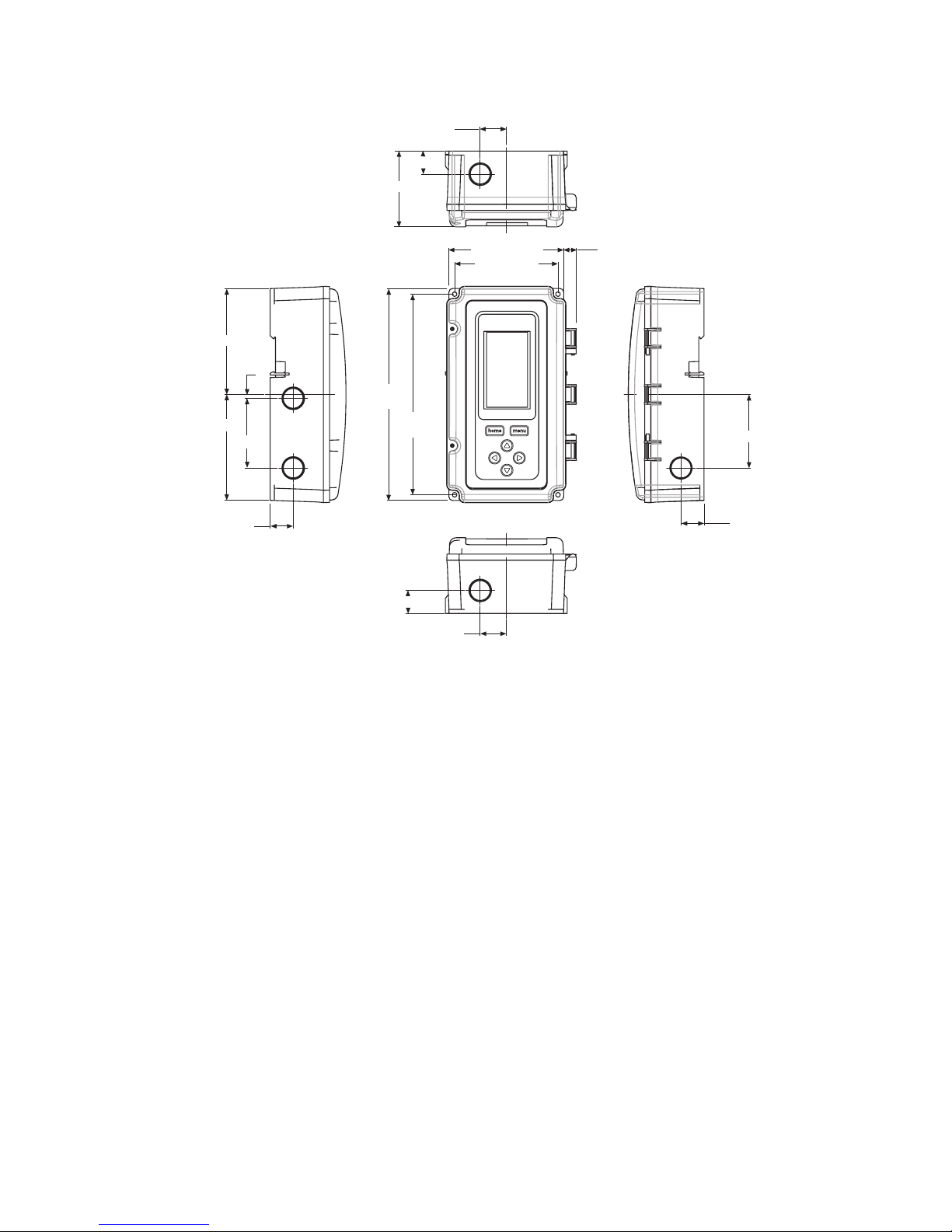
Controller Dimensions
Fig. 1. T775U Dimensions in inches (mm).
BEFORE INSTALLATION
Review the “Specifications” on page 37 before
installing the controller.
When Installing This Product
1. Read these instructions carefully. Failure to follow
them could damage the product or cause a hazardous condition.
2. Check ratings given in instructions and on the product to ensure the product is suitable for your application.
3. Installer must be a trained, experienced service
technician.
4. After installation is complete, check out product
operation as provided in these instructions.
INSTALLATION AND SETUP
The following installation procedures are typically
performed in the order listed:
1. Mounting — see “Mounting” below.
2. Wiring — see “Wiring” on this page.
3. Checkout — see page 10.
4.
Interface and Programming overview – see page 11.
5. Setup – see page 13.
6.
Programming the Controller with no Reset – see page 25
or
Programming the Controller with Reset – page 28.
7. Scheduling (optional)— see page 33.
Additional topics are:
• Sensor calibration begins on page 10.
• Interface overview begins on page 11.
• Summary menu begins on page 37.
• Troubleshooting begins on page 37.
MOUNTING
This section describes the mounting procedures for the
controller and temperature sensor(s).
Controller Mounting
IMPORTANT
Avoid mounting in areas where acid fumes or
other deteriorating vapors can attack the metal
parts of the controller circuit board, or in areas
where escaping gas or other explosive vapors
are present.
IMPORTANT
The controller must be mounted in a position that
allows clearance for wiring, servicing, and
removal.
M24546
4 13/32 (112.1)
1/2 (12.4)
3 31/32 (101)
7 23/32
(196)
8 5/32
(207.1)
2 15/16 (74)
7/8 (22.5)
1 (25.5)
4 1/16 (103.4)
4 1/16 (103.4)
1/64 (3.8)
2 11/16 (68.1)
7/8 (22.5)
2 13/16 (71.8)
7/8 (22.5)
1 (25.5)
7/8 (22.5)
TOP
BOTTOM
LEFT RIGHT
FRONT VIEW
T775U SERIES 2000 CONTROLLER WIRING
62-0255–05 4
Use a screwdriver to pry out only the knockouts that you
will use.
If mounting on DIN rail, be sure to remove the knockouts
before mounting. See “Controller Wiring” on page 7 and
Fig. 11 on page 8 for recommended knockout usage and
locations. If you do not use an opened knockout be sure
to cover it.
Mount the controller on any convenient interior location
using the four mounting holes provided on the back of the
enclosure using #6 or #8 screws (screws are not provided
and must be obtained separately). Use controller
dimensions in Fig. 1 on page 3 as a guide.
The controller may be mounted in any orientation.
However, mounting in the orientation shown in Fig. 1 on
page 3 permits proper viewing of the LCD display and use
of the keypad.
Humidity, Pressure, and Universal
Sensor(s) Mounting and Location
These sensors may be mounted on a wall or panel.
Follow the installation instructions specific to the sensor
you are installing.
Temperature Sensor(s) Mounting and
Location
Temperature sensors may be located up to 1,000 feet
(304 m) from the T775U controller. See Table 4 on
page 11 for calibration guidelines.
The sensors may be mounted on a wall or panel for
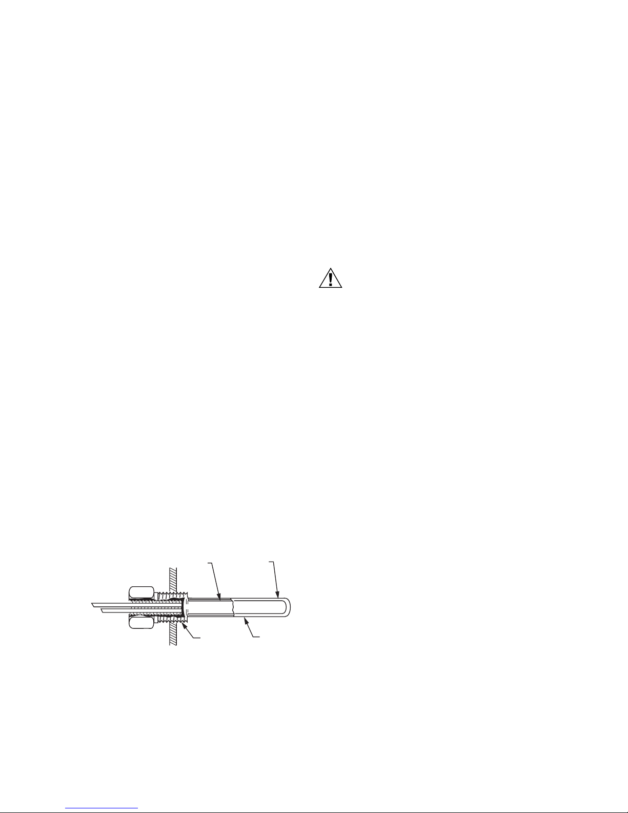
sensing space temperature, strapped to a pipe or inserted
in an immersion well (see Fig. 2) for hot or cold water
sensing, or taped to a standard cap or bulb holder for duct
air sensing. To prevent moisture or condensation entering
the sensor through the lead wire holes, mount the sensor
with the lead wires exiting the bottom of the sensor.
NOTES:
1. The included sensor is not designed for very
wet applications. For immersion applications,
an immersion well is used.
2. Heat conductive compound must be used in
immersion wells.
3. See “Temperature Sensors (Sensor A or B)”
on page 2 for this type of installation.
Fig. 2. Sensor inserted in immersion well.
NOTE: Multiple sensors may be parallel-series wired to
sense average temperatures in large spaces.
See Fig. 3 on page 5.
WIRING
All wiring must comply with applicable electrical codes
and ordinances, or as specified on installation wiring
diagrams. Controller wiring is terminated to the screw
terminal blocks located inside the device.
The remainder of this section describes the sensor wiring
and the T775U controller wiring.
Wiring Connections Access
To access the wiring connections, remove the two screws
on the left side of the enclosure and gently swing open the
top. Be careful to not stress the ribbon cables that
connect the keypad and LCD display to the controller
circuit board.
Temperature Sensor Wiring
CAUTION
Electrical Shock Hazard.
Can short equipment circuitry.
Make sure that metal tube of sensor does not
short against T terminals in wall-mounted case.
IMPORTANT
Poor wiring practices can cause erratic readings
from the sensor. Avoid the following to ensure
proper operation:
• Do not route the temperature sensor wiring with
building power wiring.
• Do not locate the temperature sensor wiring next
to control contactors.
• Do not locate the temperature sensor wiring near
electrical motors.
• Do not locate the temperature sensor wiring near
welding equipment.
• Make sure good mechanical connections are
made to both the sensor and the controller.
• Do not mount the sensor with the lead wire end
pointing up in an area where condensation can
occur.
If any of the above conditions cannot be
avoided, use shielded cable.
NOTE: Each T775 controller must be wired to its own
sensor(s). However, a benefit of the T775
controller’s accuracy is that there is no more
than a 2°F differential between any two T775
controllers.
Reset Temperature Control
If you are implementing two-sensor reset control, Sensor
A must always be the controlled temperature and Sensor
B must always be the controlling temperature.
For example, in a reset control based on outside
temperature, Sensor A must be the inside sensor and
Sensor B must be the outside sensor.
SENSOR
PLACED
IN WELL
IMMERSION
WELL
1/2 NPT
USE HEAT
CONDUCTIVE
COMPOUND
M24379
WIRING T775U SERIES 2000 CONTROLLER
5 62-0255–05
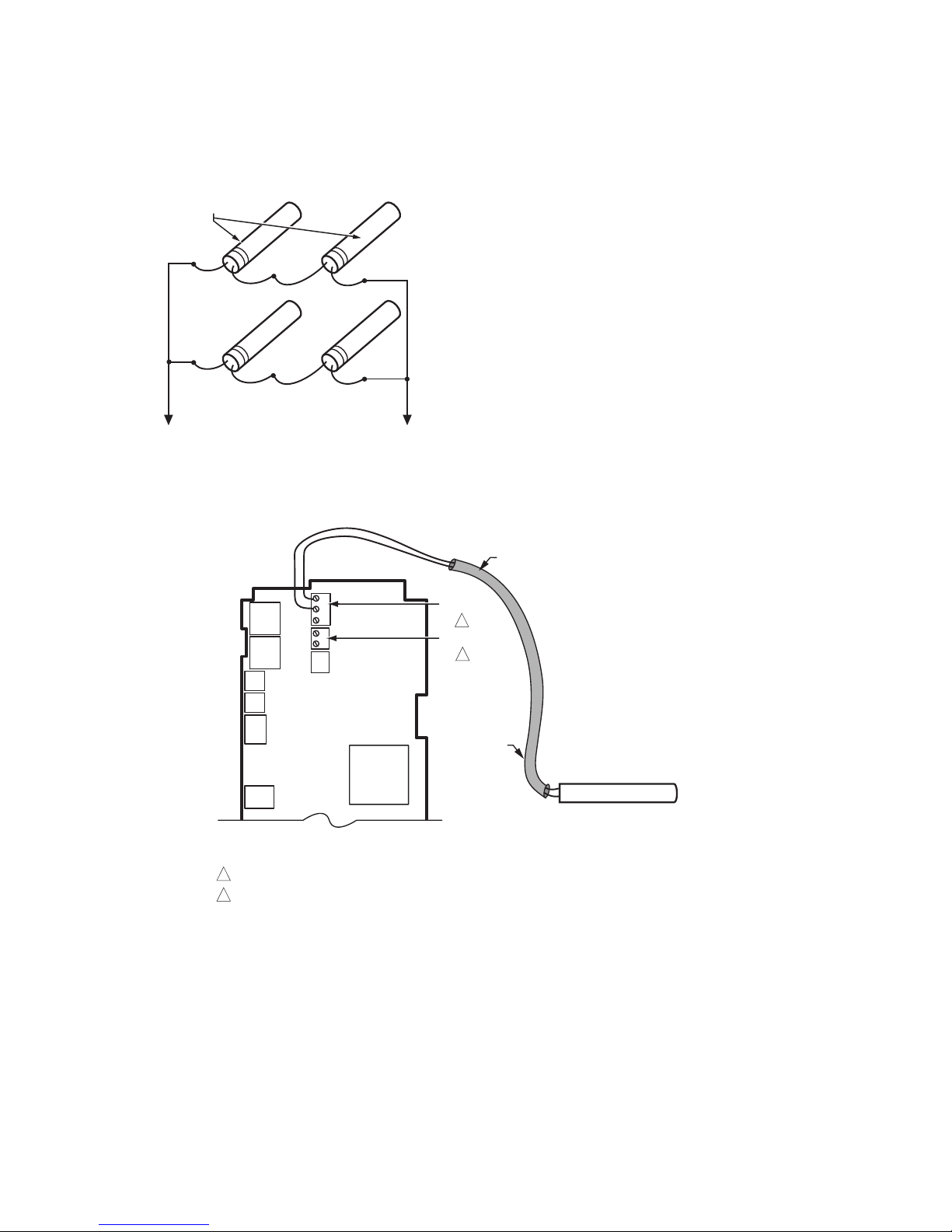
Multiple Parallel Temperature Sensors
Multiple sensors can be parallel-series wired to sense
average temperatures in large spaces. To maintain
control accuracy, the number of sensors to be parallelseries wired must be of the n
2
power (for example, 4, 9,
16, etc.). See Fig. 3.
Fig. 3. Parallel-series wiring of sensors.
Temperature Sensor Wire Type and Size
Temperature sensors use standard AWG 18/2 unshielded
wire. For cable runs greater than 25 feet or where
electrical interference may be a problem, shielded cable
is recommended. See Fig. 4.
Refer to “Temperature Sensor Calibration” on page 10 for
wire size selection where cable runs are longer than 25
feet.
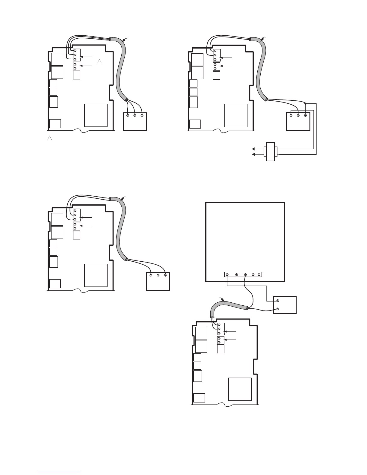
Fig. 4. Sensor Wiring — 2-wire shielded cable connection from Sensor A to temperature sensor.
Humidity, Pressure, and Universal Sensor
Wiring
Sensors with a 0-5 Vdc, 0-10Vdc or 4-20mA input to the
T775U must be wired to the Sensor A terminal. Sensor B
is used only as a temperature input.
Sensors use standard AWG 18 unshielded wire. For cable
runs greater than 25 feet, shielded cable is
recommended.
The sensors in Fig. 5 – 8 beginning on page 6 are
examples and illustrate voltage and current wiring for 3wire and 2-wire sensors to the Sensor A terminal. For
terminal wiring details, see Fig. 11 and Table 2 on page 8.
Other sensors are supported. See sensor descriptions on
page 2.
NOTES:
1. Other transmitters can be wired in the same
manner. For example, the 0-10Vdc wiring
shown in Fig. 5 on page 6 with the H76XX
sensor can also be done with the P7640 or
any other transmitter.
2. The T775U V terminal outputs 18 Vdc.
TO T775 CONNECTIONS (SENSOR A) OR (SENSOR B).
SENSORS
M24548
M24549A
SENSORS A AND B ARE POLARITY INSENSITIVE WHEN USING A 1097 OHM PTC TEMPERATURE SENSOR.
SENSOR B IS USED ONLY IN RESET APPLICATIONS ON THE T775U20006.
1
SHIELDED
CABLE
SHIELDED
CABLE
SENSOR
NOTE: SHIELDED CABLE MUST BE
CONNECTED TO A SEPARATE EARTH
GROUND.
HOWEVER, DO NOT GROUND
SHIELDED CABLE AT SENSOR END.
NOTE: TO MINIMIZE NOISE PICKUP,
MAKE SENSOR CONNECTION FROM
SHIELDED CABLE AS CLOSE AS
POSSIBLE TO SENSOR BODY.
T
T
T
T
SENSOR A
SENSOR B
1
2
2
T775U SERIES 2000 CONTROLLER WIRING
62-0255–05 6
Fig. 5. Sensor Wiring — 3-wire shielded cable
connection from Sensor A to 0-10 Vdc sensor
(H76xx humidity sensor shown).
Fig. 6. Sensor Wiring — 2-wire shielded cable
connection from 4-20 mA sensor to
T775 controller (loop powered wiring).
Fig. 7. Sensor Wiring — 2-wire shielded cable
connection from Sensor A to a 0-10 Vdc sensor
using separate transformer.
Fig. 8. Sensor Wiring — 2-wire 4-20mA sensor input
to T775 controller using a separate (Vdc only)
transformer.
M24550
THE T775U WILL ONLY ACCEPT 0-10 VDC AND 4-20 MA SENSORS.
IF REPLACING AN H775 CONTROLLER THAT USES A C7600B OR OTHER
2-10 VDC SENSOR, THE SENSOR MUST BE REPLACED. REPLACE THE
C7600B2008 SENSOR (2-10VDC OUTPUT) WITH THE H7655A1001
(0-10 VDC OUTPUT) SENSOR. THE H7655A1001 SENSOR USES THE SAME
ENCLOSURE STYLING AND WIRING AS THE C7600B.
1
NOTES:
1. SHIELDED CABLE MUST BE
CONNECTED TO A SEPARATE
EARTH GROUND. HOWEVER,
DO NOT GROUND SHIELDED
CABLE AT SENSOR END.
2. TO MINIMIZE NOISE PICKUP,
MAKE SENSOR CONNECTION
FROM SHIELDED CABLE AS
CLOSE AS POSSIBLE TO
SENSOR BODY.
EXAMPLE OF
H76XX HUMIDITY
SENSOR;
0-10 VDC
CONNECTION
SENSOR A
1
SENSOR B
C
S
V
T
T
VO
GND
VIN
CSV
SHIELDED CABLE
M24890
A
V
S
NOTES:
1. SHIELDED CABLE MUST BE
CONNECTED TO A SEPARATE
EARTH GROUND. HOWEVER,
DO NOT GROUND SHIELDED
CABLE AT SENSOR END.
2. TO MINIMIZE NOISE PICKUP,
MAKE SENSOR CONNECTION
FROM SHIELDED CABLE AS
CLOSE AS POSSIBLE TO
SENSOR BODY.
3. THE T775 HAS AN INTEGRAL LOAD OF 500 OHMS, WHICH RESULTS IN A
10V DROP AT 20MA. TO USE LOOP POWERED WIRING, THE SENSOR MUST
BE CAPABLE OF OPERATION WITH 8V OR LESS ACROSS ITS TERMINAL.
SENSOR A
SENSOR B
T
T
SHIELDED CABLE
PWR
OUT
COM
C
S
V
M24551
S
C
NOTES:
1. SHIELDED CABLE MUST BE
CONNECTED TO A SEPARATE
EARTH GROUND. HOWEVER,
DO NOT GROUND SHIELDED
CABLE AT SENSOR END.
2. TO MINIMIZE NOISE PICKUP,
MAKE SENSOR CONNECTION
FROM SHIELDED CABLE AS
CLOSE AS POSSIBLE TO
SENSOR BODY.
EXAMPLE OF
P7640A
PRESSURE
SENSOR;
0-10 VDC
CONNECTION
SENSOR A
SENSOR B
T
T
SHIELDED CABLE
PWR
OUT
COM
C
S
V
L1
(HOT)
L2
24 VAC
M24889A
S
C
NOTES:
1. SHIELDED CABLE MUST BE
CONNECTED TO A SEPARATE
EARTH GROUND. HOWEVER,
DO NOT GROUND SHIELDED
CABLE AT SENSOR END.
2. TO MINIMIZE NOISE PICKUP,
MAKE SENSOR CONNECTION
FROM SHIELDED CABLE AS
CLOSE AS POSSIBLE TO
SENSOR BODY.
EXAMPLE OF P7640A 4-20 MA SENSOR CONNECTION
SENSOR A
SENSOR B
T
T
SHIELDED CABLE
C
S
V
PWR ZEROCOMOUT
+
–
12-30 VDC
POWER SUPPLY
WIRING T775U SERIES 2000 CONTROLLER
7 62-0255–05
Controller Wiring
WARNING
Electrical Shock Hazard.
Can cause severe injury, death or property
damage.
Disconnect power supply before beginning wiring,
or making wiring connections, to prevent electrical
shock or equipment damage.
CAUTION
Do not use 24 Vac power to power any external
loads if 120 Vac or 240 Vac is used to power
the T775U.
CAUTION
A separate earth ground is required.
Equipment damage can result if the earth ground
is not connected. See Fig. 9 and Table 2 on
page 8.
CAUTION
Equipment Damage Hazard.
Electrostatic discharge can short equipment
circuitry.
Ensure that you are properly grounded before
handling the unit.
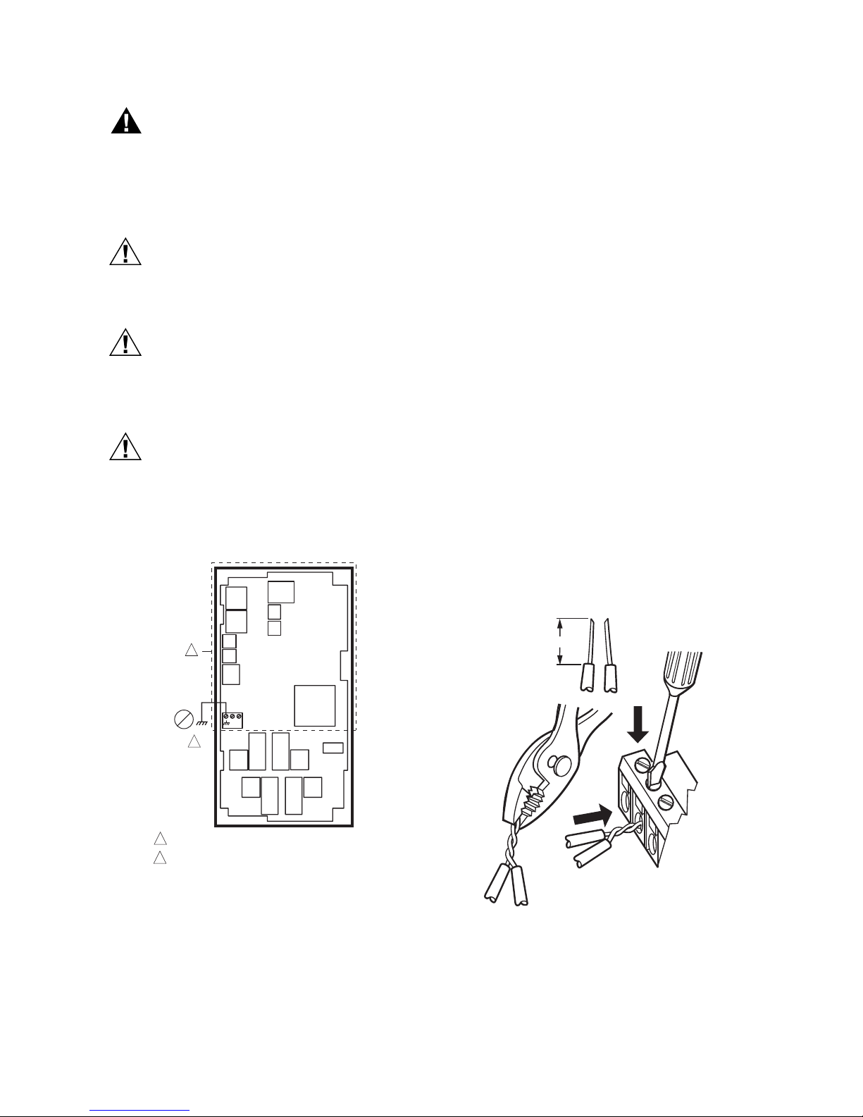
Fig. 9. Earth Ground.
IMPORTANT
Poor wiring practices can cause erratic readings
from the sensor. To ensure proper operation,
ensure that good mechanical connections are
made to both the sensor and the controller.
IMPORTANT
When wiring the input power, only one source of
power can be applied to the T775U (24 Vac or
120 Vac or 240 Vac).
See Fig. 11 on page 8 for locating the appropriate power
input, remote sensors input, low voltage, contact closure,
and load output terminals.
Access to the terminals can be gained through standard
conduit knockouts (A through E in Fig. 11 on page 8)
located around the perimeter of the enclosure:
• Knockouts A and B should be used only for sensor and
low-voltage wiring.
• Knockouts C, D, and E can be used to gain access to
the load relay output terminals and 120/240 Vac power
wiring.
Controller Wiring Method
Wire the sensors and outputs, then wire the power
connection.
Each terminal can accommodate the following gauges of
wire:
• Single wire – from 14 AWG to 22 AWG solid or
stranded
• Multiple wires – up to two 22 AWG stranded
For 24, 120, or 240 Vac power connections:
Single wire – from 14 to 18 AWG solid or stranded
Using Fig. 10 on page 7 as a guide, prepare wiring for the
terminal blocks, as follows:
1. Strip 1/2 in. (13 mm) insulation from the conductor.
2. Cut a single wire to 3/16 in. (5 mm). Insert the wire
in the required terminal location and tighten the
screw.
3. If two or more wires are being inserted into one terminal location, twist the wires together a minimum
of three turns before inserting them to ensure
proper electrical contact.
4. Cut the twisted end of the wires to 3/16 in. (5 mm)
before inserting them into the terminal and tightening the screw.
5. Pull on each wire in all terminals to check for good
mechanical connection.
Fig. 10. Attaching two or more wires at terminal
blocks.
C
+
W
1
2
M24296
NO HIGH VOLTAGE. CLASS 2 WIRING ONLY.
EARTH GROUND TERMINAL MUST BE CONNECTED
TO CONDUIT CLAMP LOCALLY.
1
2
1/2 (13)
1. STRIP 1/2 IN. (13 MM)
FROM WIRES TO
BE ATTACHED AT
ONE TERMINAL.
2. TWIST WIRES
TOGETHER WITH
PLIERS (A MINIMUM
OF THREE TURNS).
3. CUT TWISTED END OF WIRES
TO 3/16 IN. (5 MM) BEFORE INSERTING
INTO TERMINAL AND TIGHTENING SCREW.
THEN PULL ON EACH WIRE IN ALL
TERMINALS TO CHECK FOR
GOOD MECHANICAL CONNECTION.
M24552
T775U SERIES 2000 CONTROLLER WIRING
62-0255–05 8
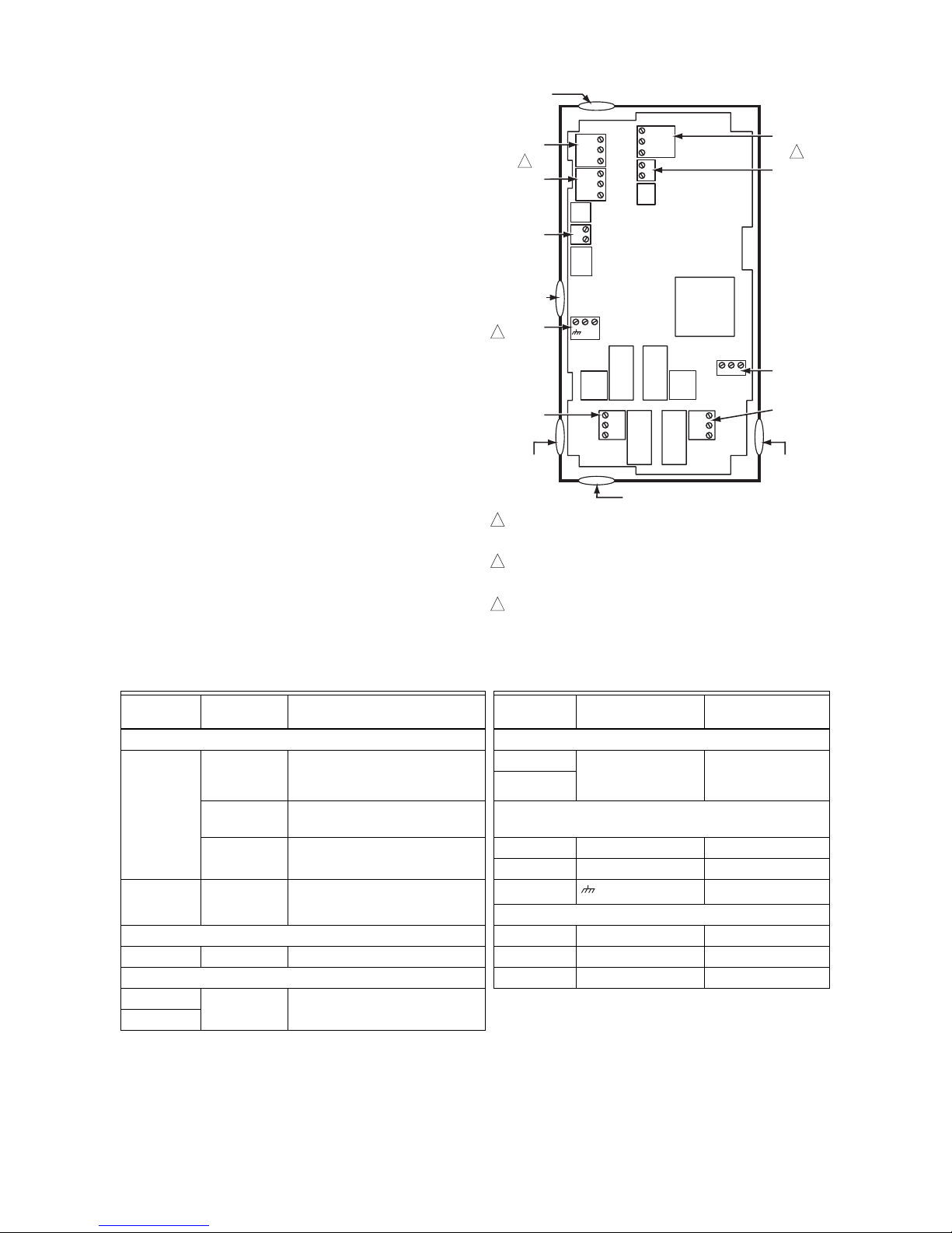
Controller Wiring Details
The wiring connection terminals are shown in Fig. 11 and
are described in Table 2. See Fig. 12 – Fig. 18 beginning
on page 9 for typical T775U wiring applications.
Fig. 11. T775U Terminal and Feature Locations.
C
NO
NC
C
NO
NC
T
T
B
R
W
+
–
+
–
B
R
W
+
–
SENSOR A
SENSOR B
MOD 2
MOD 1
KNOCKOUT A
DIGITAL
INPUT
POWER
120/240 VAC
OUTPUT
RELAY 2
KNOCKOUT D
POWER
24 VAC
OUTPUT
RELAY 1
KNOCKOUT C
KNOCKOUT E
WHEN USED FOR TEMPERATURE OR 4-20mA SENSING, SENSORS A
AND B USE THE TWO TT CONNECTIONS AND ARE POLARITY
INSENSITIVE.
FOR MOD 1 AND MOD 2 CURRENT (mA) OR VOLTAGE (VDC) OUTPUT,
USE SIGNAL (+) & COMMON (-).
FOR MOD 1 AND MOD 2 SERIES 90 OUTPUT, USE W, R, & B.
A SEPARATE EARTH GROUND IS REQUIRED FOR ANY POWER
SOURCE (24, 120, OR 240 VAC)
1
2
1
2
M24553
KNOCKOUT B
3
3
C
S
V
T
T
–
+
C
+
120
COM
240
Table 2. Description of Wiring Terminal Connections.
Connection
Termi nal
Label Description Connection Terminal Label Description
Sensors Outputs
Sensor A
a
a
For applications that do not use Reset, only Sensor A is available for use.
C – common
S – signal
V – voltage
0-10 Vdc input: Universal
sensor for humidity, pressure,
temperature, etc.
Mod 1
+ - (Vdc or mA)
W R B (Series 90)
b
b
For Series 90 connections, you must insert a 340 Ohm resistor across terminals R and W. See Fig. 17 on page 10.
The resistor is included with the controller.
Modulating Output
Mod 2
S and V 4-20mA input; see Fig. 7 on
page 6 24 Vac Power
T T
Temperature Sensor; polarity
insensitive
24V + + 24 Vac Hot
Common - 24 Vac Common
Sensor B T T Temperature Sensor; polarity
insensitive
Ground
Earth Ground
c
c
A separate earth ground is required for all installations regardless of the power source (24, 120, or 240 Vac).
120 or 240 Vac Power
Input 120 Vac 120 120 Vac Power
DI + - Digital Input (dry contact) Common COM Common
Outputs 240 Vac 240 240 Vac Power
Relay 1 NO / COM /
NC 120-240 Vac Relay Output
Relay 2
WIRING APPLICATION EXAMPLES T775U SERIES 2000 CONTROLLER
9 62-0255–05
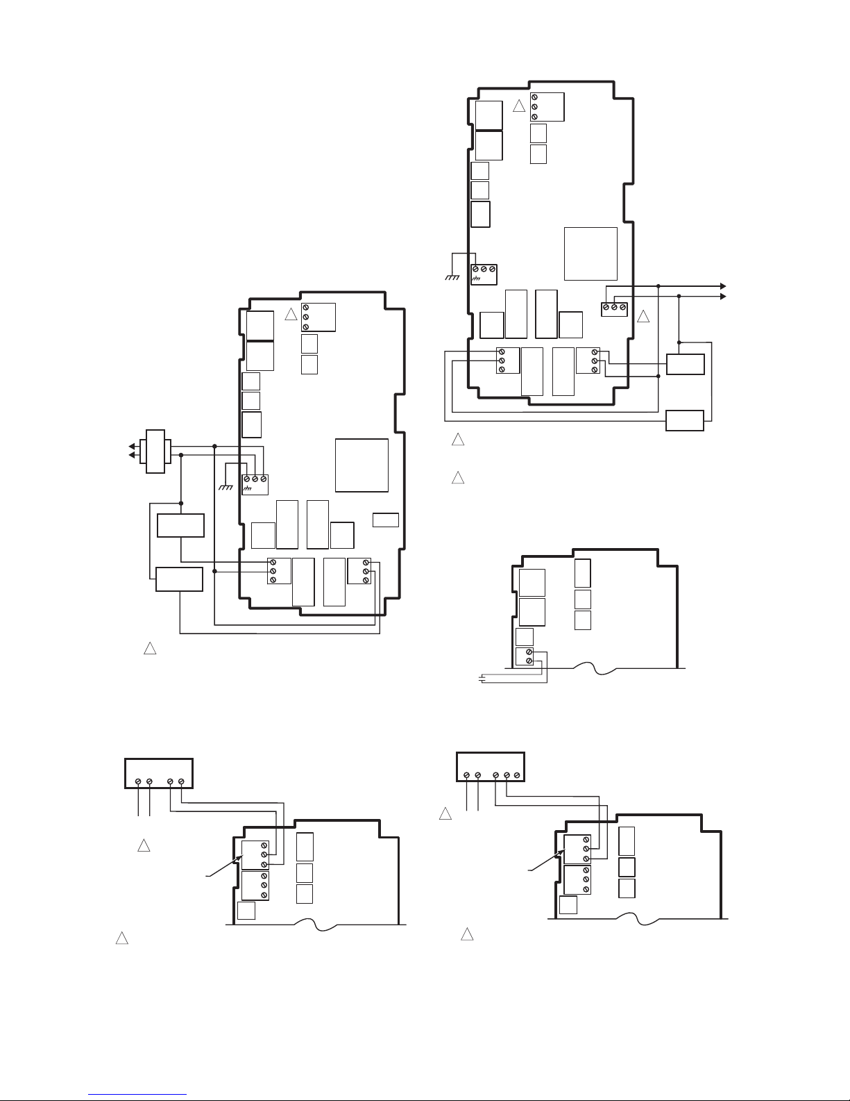
WIRING APPLICATION EXAMPLES
Fig. 12 – 18 illustrate typical controller wiring for various
applications.
NOTE: The electronic Series 90 output provided with
modulating T775 models can not drive electromechanical slidewire devices like older Series 3
modulating meters (prior to Series 6), V9055s,
and S984s.
NOTE: For a wiring example of three Series 90 Modutrol
Motors, refer to the T775A/B/M Series 2000
Electronic Stand-alone Controllers Installation
Instructions (form 62-0254).
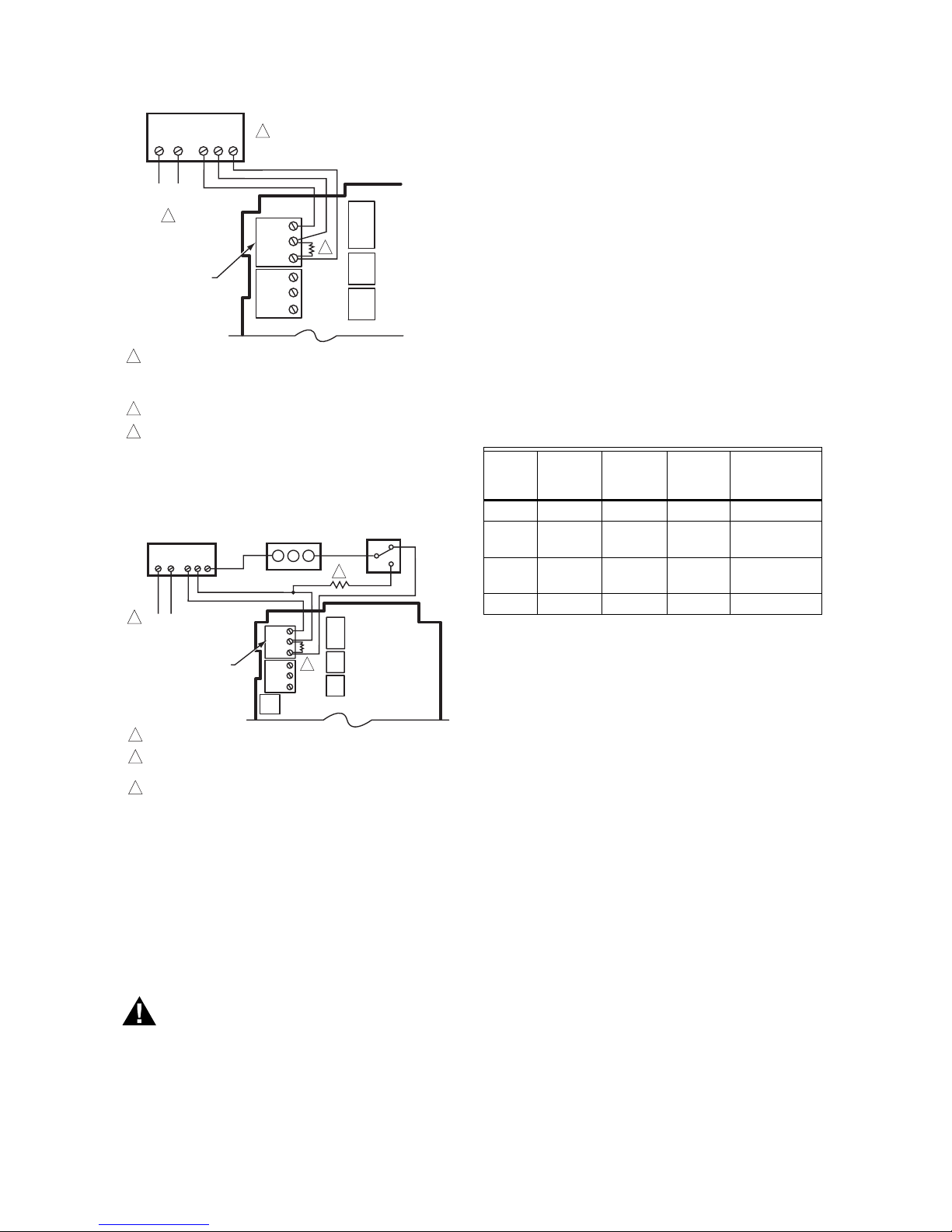
Fig. 12. Wiring for Two-stage Control – 24 Vac Input
and 24 Vac Load.
Fig. 13. Wiring for mod motor or direct coupled
actuator with 4 to 20 mA control input.
Fig. 14. Wiring for Two-stage Control with 120 or 240
Vac (120 Vac Input and 120 Vac Load).
Fig. 15. Wiring for Digital Input (dry contact).
Fig. 16. Wiring for mod motor or direct coupled
actuator with 0-10 Vdc control input.
L1
(HOT)
L2
24 VAC
COM
NO
COM
NO
M24554A
C
S
V
T
T
–
+
LOAD 2
LOAD 1
C
NO
NC
C
NO
NC
C
+
FOR SPECIFIC SENSOR WIRING (TEMPERATURE, HUMIDITY,
PRESSURE, ETC), REFER TO THE SENSOR WIRING SECTIONS
BEGINNING ON PAGE 4.
1
1
USE SEPARATE TRANSFORMER FOR T775 WHEN USING 24 VAC.
1
M24557A
MODULATING OUTPUT
TERMINAL (MOD 1)
B
R
W
+
–
B
R
W
+
–
POWER
OUTPUT
1
T1 T2
–
+
HONEYWELL MODUTROL MOTOR WITH
4-20 mA MODULATING INPUT
C
NO
NC
C
NO
NC
COM
LOAD 2
LOAD 1
NO
COM
NO
COM
120V
M24555A
2
2
FOR SPECIFIC SENSOR WIRING (TEMPERATURE, HUMIDITY,
PRESSURE, ETC), REFER TO THE SENSOR WIRING SECTIONS
BEGINNING ON PAGE 4.
FOR 240 VAC LOAD, CO NNECT TO 240 T ERMINAL.
C
+
120
COM
240
C
S
V
T
T
–
+
1
1
M24559
DIGITAL
INPUT
+
–
T1 T2 C R
POWER
OUTPUT
USE SEPARATE TRANSFORMER FOR T775 WHEN USING 24 VAC.
1
HONEYWELL MODUTROL MOTOR WITH
VOLTAGE CONTROL INPUT
1
F
M24558A
MODULATING OUTPUT
TERMINAL (MOD 1)
B
R
W
+
–
B
R
W
+
–
+
–
T775U SERIES 2000 CONTROLLER CHECKOUT
62-0255–05 10
Fig. 17. Wiring for Series 90 Modutrol Motor Control.
Fig. 18. Wiring for Changeover Relay and
Minimum Position Potentiometer used with
Series 90 Modutrol Motors.
CHECKOUT
Inspect all wiring connections at the controller terminals,
and verify compliance with the installation wiring
diagrams.
WARNING
Electrical Shock Hazard.
Can cause severe injury, death or property
damage.
Disconnect power supply before beginning wiring
or making wiring connections, to prevent electrical
shock or equipment damage.
If any wiring changes are required, first be sure to remove
power from the controller before starting work. Pay
particular attention to verifying the power connection (24,
120, or 240 Vac).
After the controller is mounted and wired, apply power.
Power Loss
The date and time settings are retained for 24 hours after
a power outage. After a power loss of more than 24 hours,
the date and time settings may need to be reentered. All
other settings are stored permanently.
Humidity, Pressure, and Universal Sensor
Calibration
A calibration parameter is available using Setup mode.
The calibration range is +/- 10% of the Min Value to Max
Value range setup for the sensor. See examples in
Ta bl e 3 .
The calibration value is set in section “1.2.2.3.
CALIBRATE (Sensor A or B)” on page 16.
Temperature Sensor Calibration
As wire length increases, resistance increases and thus
the temperature reading increases. If necessary, calibrate
the sensor input by reducing the value by the amount
shown in the Table 4 on page 11. For example, a wire run
with 18 gauge wire of 1,000 feet, requires a calibration
offset of -6.0°F.
IMPORTANT
If the calibration value in the table exceeds the
controller’s calibration limits of +/-10°F (+/-6°C),
you must use a heavier gauge wire.
For example, with a wire run of 1,000 feet you
must use 20 AWG wire or heavier in order to calibrate for wire loss within the limits of the controller.
See “1.2.2.3. CALIBRATE (Sensor A or B)” on page 16 for
the instructions to enter the calibration value.
NOTE: The resistance output on the temperature sen-
sors change at the rate of 2.2 Ohms per °F (3.85
Ohms per °C).
M24560A
TO VERIFY OUTPUT, TEST OPEN CIRCUIT VOLTAGE BETWEEN
THE MOD 1 TERMINALS W AND R.
- MINIMUM (DRIVE CLOSED) SIGNAL LESS THAN 0.17 VDC
- MAXIMUM (DRIVE OPEN) SIGNAL IS GREATER THAN 1.7 VDC
USE SEPARATE TRANSFORMER FOR T775 WHEN USING 24 VAC.
INSERT 340 OHM RESISTOR (INCLUDED) ACROSS TERMINALS R AND W.
1
2
3
MODULATING
OUTPUT
TERMINAL
(MOD 1)
B
R
W
+
–
B
R
W
+
–
T1 T2 B WR
POWER
OUTPUT
HONEYWELL ELECTRONIC
SERIES 90 MODUTROL MOTOR
1
2
3
M24561A
USE SEPAR ATE TRA NSFOR MER FOR T 775 WHEN USING 24 VAC.
A 250 OHM R ESISTOR PR OVIDES 40 % AUTHOR ITY WH EN
USING A 150 O HM MIN IMUM P OSITIO N POTENT IOME TER.
INSERT 340 OHM RESISTOR (INCLUDED) ACROSS TERMINALS R AND W.
1
2
MODULATING OUTPUT
TERMINAL (MOD 1)
B
R
W
+
–
B
R
W
+
–
T1 T2 B WR
POWER
OUTPUT
2
HONEYWELL
ELECTRONIC SERIES 90
MODUTROL MOTOR
1
W R B
MINIMUM POSITION
POTENTIOMETER
(Q20 9)
SPDT CHA NGEOVER
(H205 O R H705)
3
3
Table 3. Calibration Range Examples.
Units
Min.
Value
Example
Max.
Value
Example
Min-Max
Range
Result
Calibration
Range
PSI 100 400 300 ± 30 PSI
Inches
W.C.
-20.0 20.0 40 ± 4 in. W.C.
Pa or
kPa
-2,000 3000 5000 ± 500 Pa/kPa
% 10 100 90 ± 9%
INTERFACE OVERVIEW T775U SERIES 2000 CONTROLLER
11 62-0255–05
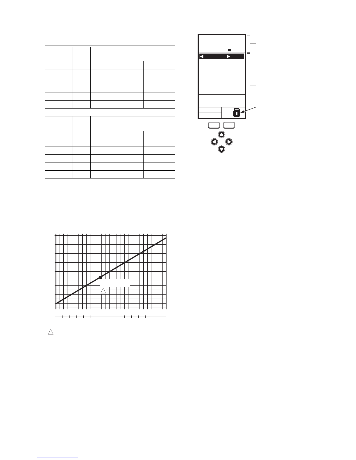
Fig. 19 shows how sensor resistance varies with
temperature for a sensor having a positive temperature
coefficient (PTC) of 2.1 Ohms per degree F (3.85 Ohms
per degree C).
Fig. 19. Sensor Resistance vs. Temperature.
INTERFACE OVERVIEW
The T775U controller uses an LCD panel and 6-button
keypad to provide status information and permit user input
of the programming, setup, and scheduling parameters.
The following figure describes the display areas of the
LCD and the keypad.
Fig. 20. LCD Display - Home Screen And Keypad.
Menu Area – On the home screen, the LCD displays the
configured relays and whether they are active. In
Program, Setup or Schedule mode, the LCD displays the
current menu selection and its order within the menu
hierarchy.
Data Area – On the home screen, the LCD displays the
sensors and outputs status. In Setup or Program mode,
the LCD displays menu choices, parameter selections,
and data values.
Lock Icon – The icon indicates the MENU button is
locked and prevents access to the Setup and Program
menus.
NOTE: Pressing and holding the HOME and MENU but-
tons simultaneously for five seconds locks/
unlocks the MENU button.
6-Button Keypad – The keypad is used to access the
menus and enter values (see “Using the LCD Panel
Interface”).
Using the LCD Panel Interface
The 6-button keypad is used to move through the menus
and enter or change parameter values.
Home Button
Pressing the HOME button at any time exits the current
Programming or Setup display screen and returns to the
home screen as shown in Fig. 20 and Fig. 21.
Menu Button
• Pressing the MENU button always displays the
Program menu. If you are in Setup mode, you exit
setup and return to the Program menu.
• Pressing and holding the MENU button for five
seconds leaves the current screen and displays
the Setup menu.
Left and Right Arrow Buttons (W and X)
Use these buttons to move backward (W) and forward (X)
through the Program and Setup menus.
Table 4. Temperature Sensor Calibration for
Resistance Loss due to Wire Length.
AWG
Rating mΩ/ft
Temperature Offset in
°F (Feet)
a
a
This is the distance from the controller to the sensor
(already accounts for round trip distance).
200 ft 500 ft 1,000 ft
14 2.5 0.46 1.14 2.28
16 4.0 0.72 1.82 3.64
18 6.4 1.16 2.90 5.82
20 10.2 1.86 4.64 9.28
22 16.1 2.92 7.32 14.64
AWG
Rating mΩ/m
Temperature Offset in
°C (Meter)
a
100 m 200 m 300 m
14 8.3 0.44 0.86 1.30
16 13.2 0.68 1.38 2.06
18 21.0 1.10 2.18 3.28
20 33.5 1.74 3.48 5.22
22 52.8 2.74 5.48 8.22
M24304
TEMPERATURE (DEGREES)
RESISTANCE (OHMS)
1403
1317
1231
114 5
1059
973
20 40 60 80 100 120 140 160 180 200 220
0 10 20 30 40 50 60 70 80 90 100
°F
°C
0-20-40
120
110
250
-40 -20 -10-30
1489
887
801
1097 ± 0.08 OHMS
AT 77°F (25°C)
POSITIVE TEMPERATURE COEFFICIENT (PTC) OF 2.1 OHMS PER °F
1
1
MOD1 40%
MOD2 60%
DI ON
HOME
RELA
YS 1 2
ON
SENSORS
SENSOR A
78
SENSOR B
84
MENU AREA
home menu
F
o
F
o
DATA AREA
LOCK ICON
6 BUTTON KEYPAD
M24563
T775U SERIES 2000 CONTROLLER INTERFACE OVERVIEW
62-0255–05 12
Up and Down Arrow Buttons (S and T)
Use these buttons to move your selection up and down
through a menu or list.
• When the desired item is highlighted, you press the X
arrow button to display that item’s content.
• When a value is displayed (e.g. 70°F), the up and
down arrows increase and decrease the value.
NOTE: Once you select an item from a list or enter a
value, pressing the W or X or HOME button
accepts your selection or value and stores it in
the controller’s memory.
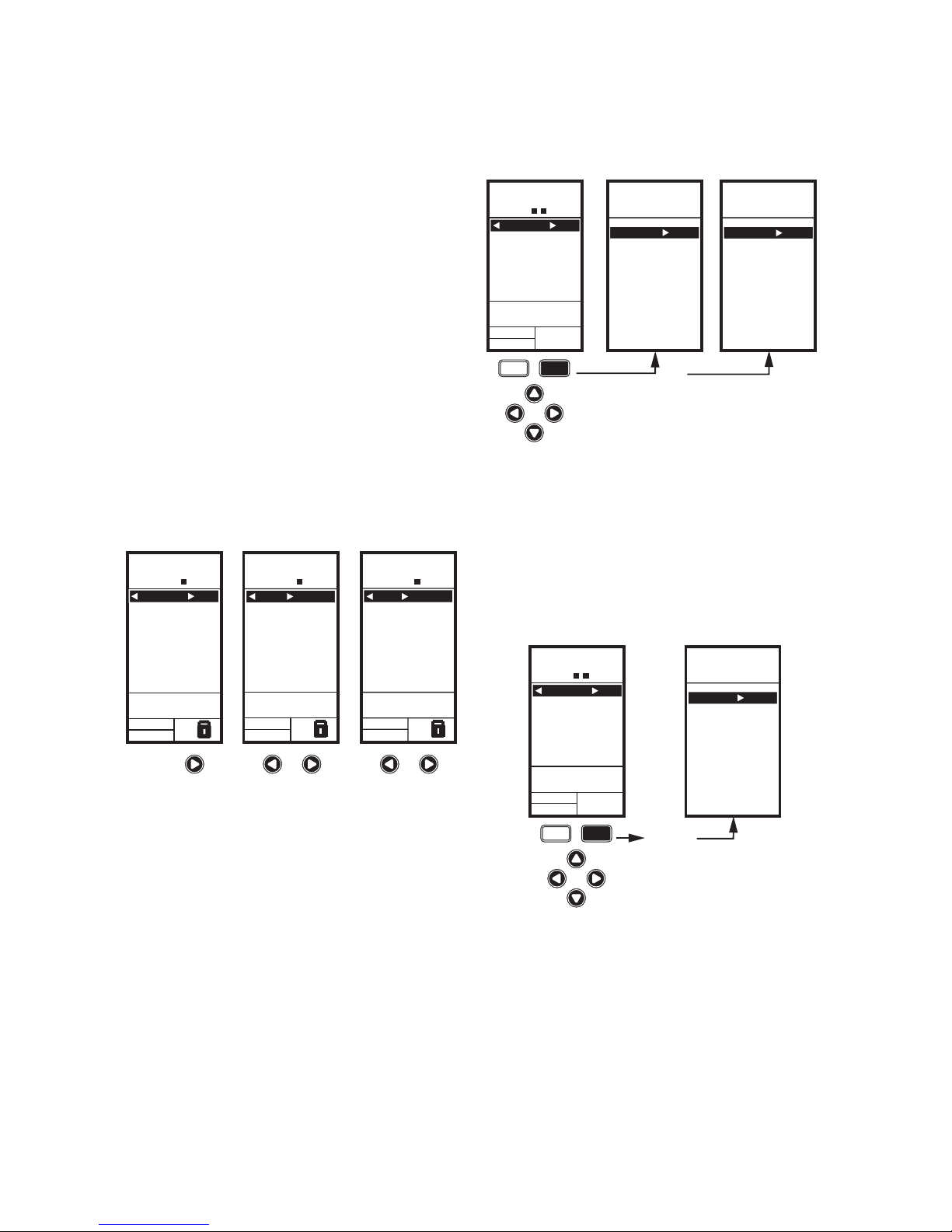
Home Screen
In the normal run state, the LCD home screen displays
the current sensed temperatures, the modulating outputs
status, the active status of the output relays, and error and
status codes.
When using Reset, the Heat/Cool setpoint(s) display on
the home screen for the Mod and Relay outputs; see
Fig. 21.
Active relays are indicated by the small black square ()
just below the relay number. Fig. 21 shows the home
screen with relay 2 energized.
Pressing the W and X buttons from the home screen
cycles through each modulating output that is paired with
the sensor it controls and the active output relays.
Fig. 21. LCD Display - Home Screen Displaying
Sensors, Mod Outputs, and Active Relays.
NOTES:
1. The modulating output home screen and the
relay home screen do not dynamically update
the active relay status, sensor values, and
modulating output percentages. The information is a snapshot taken when you press the
W or X button to display the screen.
2. In Reset mode, the home screen displays the
effective setpoint.
IMPORTANT
After four minutes of inactivity (no buttons
pressed), the LCD display reverts to the home
screen display.
Accessing the Menus
Menus are used for programming, scheduling, viewing the
summary settings, and setup of advanced options.
Program, Schedule, and Summary Menus
To access these menus from the home screen, press the
MENU button. See Fig. 22.
Fig. 22. Menus.
Depending on whether scheduling is enabled or not, the
LCD displays one of two menus as shown in Fig. 22.
Scheduling is enabled from the Setup menu’s Output
settings (see “1.3.3.1. USE SCHED” on page 21).
Setup Menu
To access the Setup menu, press and hold the MENU
button for five seconds. See Fig. 23.
Fig. 23. Setup Menu.
Using the Menus
When you are working with the menus, use the:
• Left arrow button (W) to scroll backward through the
menus
• Right arrow button (X) to select the highlighted menu
item and display its content
• Up and Down arrow buttons (S and T) to scroll up
and down through a list of items or to increase or
decrease the value of a displayed parameter
MOD1 40%
MOD2 60%
DI ON
HOME
RELAYS 1 2
ON
SENSORS
SENSOR A
78
SENSOR B
84
o
o
F
F
MOD1 40%
MOD2 60%
DI ON
HOME
RELAYS 1 2
ON
o
F
o
F
REL 2 ON
HEAT
SETPOINT
60
SENSOR A
62
RT 12345 HRS
DI ON
HOME
RELAYS 1 2
ON
MOD 1 40%
COOL
SETPOINT
74
SENSOR A
62
o
o
F
F
MOD1 40%
MOD2 60%
M24564
MENU
PROGRAM
EXIT
home
menu
OR
MENU DISPLAY WHEN
SCHEDULING IS NOT SET
MENU DISPLAY WHEN
SCHEDULING IS SET
MENU
MOD1 40%
MOD2 60%
DI ON
HOME
RELAYS 1 2
ON
F
o
F
o
SENSORS
SENSOR A
78
SENSOR B
84
PROGRAM
SCHEDULE
SUMMARY
EXIT
M24565
home
menu
SETUP
MOD1 40%
MOD2 60%
DI ON
HOME
RELAYS 1 2
ON
FIVE
SECONDS
F
o
F
o
SENSORS
SENSOR A
78
SENSOR B
84
SENSORS
OUTPUTS
EXIT
M24566
 Loading...