

T7560A,B,C Digital Wall Module
HONEYWELL EXCEL 5000 OPEN SYSTEM
INSTALLATION INSTRUCTIONS
BEFORE INSTALLATION
All wiring must comply with local electrical codes and
ordinances or as specified on installation wiring diagrams.
Digital Wall Module (DWM) wiring can be sized from 16 to 22
AWG (1.5 to 0.34 mm
max. length of wire from a device to a DWM is 164 ft (50 m).
Twisted pair wire is recommended for wire runs longer than
100 ft (30.5 m).
2
), depending on the application. The
CAUTION
EMI Noise Introduction.
Risk of erratic system operation.
Keep wiring at least one ft (305 mm) away from large
inductive loads such as motors, line starters, lighting
ballasts and large power distribution panels. During
installations, try to avoid areas of high EMI noise.
Run DWM wiring separately from 50 Vac or greater
power wiring.
WARNING / CAUTION
Risk of electric shock or equipment damage!
► Do not touch any live parts inside the DWM housing.
► Disconnect the power supply before making connections
to or removing connections from the DWM's terminals.
► Do not reconnect the power supply until you have com-
pleted the installation.
► If the DWM is powered via terminal 8 and connected to
earth ground, then the cable must be shielded.
► Observe precautions for handling electrostatic sensitive
devices.
Table 1. Types of DWM
T7560A
T7560B
T7560C
1
Tmp = Temperature sensor; Hum = Humidity sensor
Table 2. Controller SW requirements for powering via
VAV
W7751H
1.02.15 1.00.04 1.00.02 1.00.03 1.00.03
NOTE: A software module (ModAL module GNRSC02A) is
sensor1 setpoint bypass fan override
Tmp wheel button button
Tmp/Hum wheel button button
Tmp/Hum - - -
terminal 5 and new LCD signaling
Fan Coil Unit
W7752 W7754
available to adapt the DWM to the respective Excel
20, 50, 100, 500, 600, or 800 controller, making any
further configuring obsolete. Contact your local
Honeywell distributor for further details.
Hydronic
W7762
Chilled Ceiling
W7763
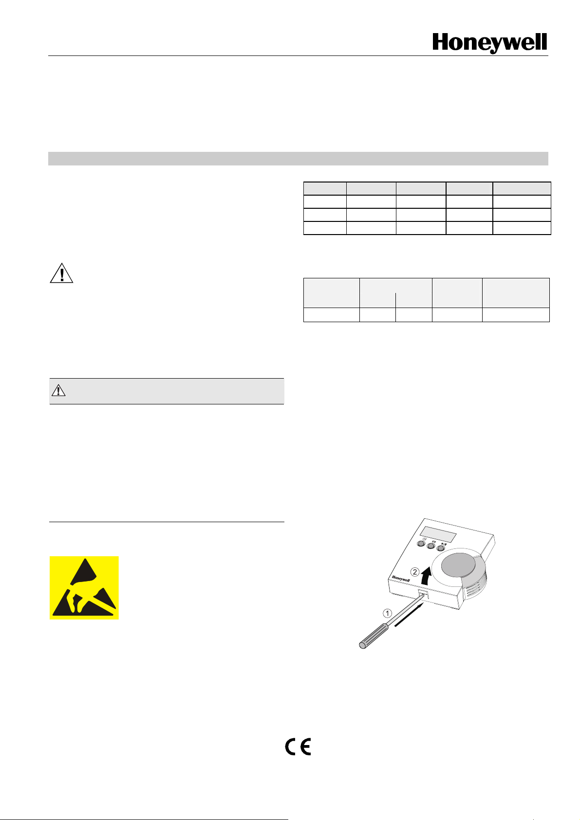
DWM DISASSEMBLY
The T7560A,B,C comes packed with a sub-base that mounts
separately for ease of installation. The cover is fixed by a
latch on the underside of the unit. Remove the cover as
shown in Fig. 1 (T7560A,B) or Fig. 2 (T7560C):
1. Insert the tip of an awl or a similar narrow, pointed object
into the small hole in the latch (T7560A,B) or simply
depress the latch by hand (T7560C).
2. Pry off the cover.
® U.S. Registered Trademark
Copyright © 2009 Honeywell Inc. • All Rights Reserved EN1B-0146GE51 R0309B
Fig. 1. DWM disassembly (T7560A,B)
T7560A,B,C DIGITAL WALL MODULES
Fig. 2. DWM disassembly (T7560C)
INSTALLATION
Mount the DWM on an inside wall approximately 54 in.
(1.3 m) from the floor (or as specified on the installation
drawings) to allow exposure to the average zone temperature.
Do not mount the DWM on an outside wall, on a wall
containing water pipes or near air ducts. Avoid locations that
are exposed to discharge air from registers or radiation from
lights, appliances, or the sun.
The DWM is furnished with a terminal block; all field wiring
connections are made to these eight terminals.
The DWM has to be mounted in vertical position with the LCD
display to the top.
Mount the subbase directly on a wall (see Fig. 3) using the
type of screws appropriate for the wall material.
Fig. 3. Mounting of DWM (T7560A,B shown)
See Fig. 6 for T7560A,B,C mounting dimensions.
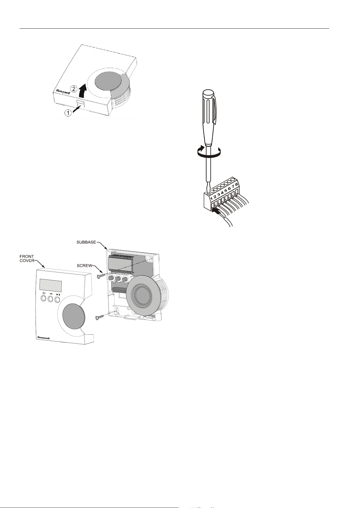
Wiring
Wire the terminal blocks as follows:
1. Strip 3/16 in. (5 mm) of insulation from the conductor.
2. Insert the wire in the required terminal location and tighten
the screw to complete the termination.
IMPORTANT
Deviation from this rule can result in improper
electrical contact. See Fig. 4.
3. Verify DWM is wired according to Fig. 4.
NOTE: For specific wiring requirements, see the following
Power section.
Terminals
1 = Common
2 = Temperature sensor
3 = Setpoint (T7560C: Do not connect!)
4 = Bypass/fan* (T7560C: Do not connect!)
5 = LED input (T7560C: Do not connect!)
6 = Bypass** (T7560C: Do not connect!)
7 = Humidity output
8 = 24 Vac / 22 Vdc input
* With Excel 10 Controllers:
W7750 (CVAHU), W7752 (FCU),
and XL12
2
** With Excel 10 Controllers:
W7751H (VAV), W7762 (HYD), and
W7763 (CHC)
For W7753 (UV) and W7761 (RIO),
see below.
NOTE
1
Fig. 4. Wiring of DWM
NOTE: If connected to W7753 (UV) Controller, both
terminals 4 and 6 must be connected.
W7761 Remote I/O Controller supports only
terminals 2 (temperature), 7 (humidity), and
1 (common), as well as terminal 8 as voltage supply.
Wiring with terminal 8 is not necessary if:
a) an FCU or CHC controller with software is
connected (see table 2); or
b) an Excel 500 with 6V/8V/10V signaling from the
controller is used.
The T7560A must then be powered by terminal 5.
Power
The DWM can be powered as follows:
• T7560A: preferably via the 5 V LED input (terminal 5); via
terminal 8 is also possible
• T7560B,C: via the 24 Vac/dc input (terminal 8).
IMPORTANT
The DWM can be powered only via terminal 5 with
those controllers listed in Table 2, and if a
SW version listed in Table 2 or higher is installed.
If the DWM is powered via terminal 5, the Excel 10
controller must be configured for LCD_DISPLAY
(LED output continuously ON).
NOTE: The 24 Vac power supply is needed only with the
T7560B,C DWM (for the humidity sensor).
EN1B-0146GE51 R0309B
2

Alternatively, a DC voltage source with 5...15 V can
be connected to terminal 5 (see IMPORTANT note
above).
Alternatively, a DC voltage source with 18...30 V
(e.g. 22 Vdc from W7750 CVAHU) can be connected
to terminal 8.
Input ratings
Terminal 5:
min. 5 Vdc I
max. 15 Vdc I
max
max
3 mA
4 mA
or LED output of any Excel 10 controller
Terminal 8:
24 Vac from controller; I < 6 mA
or
18 Vdc (I < 2.4 mA) ... 30 Vdc (I < 10 mA)
Controllers with the following output ratings can be connected
to terminal 5
(ratings are met by all Excel 10 controllers):
• 5 V with 389 Ω
• 4.3 V with 100 Ω
• 14.3 V with 1.5kΩ
Use up to 16 AWG (1.5 mm
(1.0 mm
2
) wire for connecting 24 Vac power to terminal 8.
2
) with a minimum of 18 AWG
T7560A,B,C DIGITAL WALL MODULES
Fig. 5. Mounting cover of T7560A,B DWM
CAUTION
Low Voltage Equipment.
Risk of equipment damage.
The 24 Vac power source for the DWM must be a
Class II Power Source. To conform to Class II
restrictions, transformers must not be larger than
100 VA. A transformer that is CE certified and meets
the Low Voltage Device (LVD) requirements must be
used in Europe for all installations of this product.
The DWM power usage is < 0.2 VA at 24 Vac. The DWM
does not require a dedicated transformer. The DWM can get
power from any convenient location in the 24 Vac power
circuit.
The 24 Vac power can come from the 24 Vac power terminals
on the nearest controller or directly from a 24 Vac
transformer, whichever is closer.
When all wiring is complete, attach the cover of the DWM as
is shown in Fig. 5.
NOTE: Make sure that the latch on the underside of the
DWM engages properly.
Fig. 6. DWM dimensions in inches (mm)
EN1B-0146GE51 R0309B
3

T7560A,B,C DIGITAL WALL MODULES
CONFIGURATION (T7560A,B)
After installation, the T7560A,B DWM must be configured in
order to perform as desired. This is done by using the buttons
and the setpoint wheel (see Fig. 7).
Fig. 7. Control elements of T7560A,B DWM
Normal Operating Mode
After the DWM is powered up by the controller, it will display
the room temperature and will operate as configured by
default; the respective default setting is marked with an
asterisk in the following.
After power-up, all display segments are switched on for
approx. one second (see Fig. 8).
AUTO
MANU
PROG
Fig. 8. Display of all segments after power-up
Entering Configuration Mode
1. Press FAN OVERRIDE for at least 5 seconds.
2. Press UNIT ENABLE, then release FAN OVERRIDE,
hold UNIT ENABLE for at least 5 seconds.
3. Release UNIT ENABLE.
RESULT: The display shows
ready for configuration (see below).
4. Press and hold FAN OVERRIDE while turning the
setpoint wheel to select the parameter number.
RESULT: The parameters with their currently set
values are displayed; the
value indicates the currently set value (see
below for values).
5. Release FAN OVERRIDE and turn the setpoint wheel to
select the parameter value.
6. Confirm selection by pressing UNIT ENABLE.
7. Repeat steps 4 to 6 to configure next parameter, or
press BYPASS to leave the configuration mode.
NOTE: After approx. 10 seconds without further action, the
DWM automatically falls back to normal mode.
and the DWM is
≡ behind the
In the following, default settings are marked with an asterisk
(*).
P1 Setpoint Type Setting / Scale Type Setting
•
•
*
• Celsius absolute
P2 Room Temperature Setting
• Do not display room temperature
* Display room temperature
•
P3 Bargraph Use Setting
•
•
•
*
P4 Controller Type Setting
*
•
•
•
•
•
P5 Pin 4 (Bypass/Fan) Grounding
•
*
P6 Device type
This item configures different devices.
IMPORTANT:
Fahrenheit relative
Fahrenheit absolute
Celsius relative
(setpoint, only)
Display room temperature and humidity,
alternating every 5 seconds (T7560B, only)
No Fan
Auto, Off, On
Auto, Off, 2 Speeds
Auto, Off, 3 Speeds
New LCD signaling from controller (only for
controllers and SW versions as listed in
Table 2 or higher, in which case this setting
must be selected; set Excel 10 controller
to LCD_DISPLAY)
LED override mode from controller,
US signaling (100 ms pulses);
with contr. W7750, W7751, W7753, W7761,
and XL12
LED override mode from controller,
European signaling (500 ms pulses);
with contr. W7752, W7762, W7763, and XL12
(in the case of SW versions as listed in
Table 2 or higher, select
LED occupancy mode from controller,
European signaling (500 ms pulses);
with contr. W7752, W7762, W7763, and XL12
Same as
Excel 500 signaling from controller
(10 V, 8 V, 6 V)
Pin 4 not shorted to GND if override is
pressed (UV-controller, W7753)
Pin 4 shorted to GND if override is pressed
Stay on P6:1 and do not change to other
configurations.
).
EN1B-0146GE51 R0309B
4

T7560A,B,C DIGITAL WALL MODULES
j
P7 Temperature offset
*
P8 Switch back fan / temperature offset if unoccupied
*
• enable FAN Key / disable Setpoint Key
•
•
To "disable" means to switch back to FAN= auto / Setpoint
offset = zero and disable operation.
To "enable" means to make normal operation possible (no
action if unoccupied).
"Unoccupied" means:
• Effective Unoccupied (moon on continuously)
or
• Override Unoccupied (moon flashing).
"Occupied" means:
• Effective Occupied (sun on continuously)
or
• Override Occupied (sun flashing).
P8 works only with configuration P4:1: LCD signalling.
The setpoint will be set to zero only if set to relative: P1:1 and
P1:3.
P9 Limit setpoint
•
PA Limit for humidity low limit output value
•
Temperature offset; values of 0 through 99
are valid. 50 = no change (default),
49 = -0.1 °C, 51 = +0.1 °C, etc.
This offset varies the LCD display value, only.
It must be set separately in the XL10 controller.
enable FAN Key / enable Setpoint Key
disable FAN Key / enable Setpoint Key
disable FAN Key / disable Setpoint Key
-
Limit setpoint to ±0 … 5 °C (if set to Celsius) or to
0 … 9 °F (if set to Fahrenheit).
Default (if set to Celsius):
Default (if set to Fahrenheit):
Example (units set to Celsius): A setting of
means that the set point offset is limited to -3 to +3 °C.
Example (units set to Fahrenheit): A setting of
means that the set point offset is limited to -8 to +8 °F.
-
Limit the output value to 10 … 20% relative humidity in
steps of 5%.
This affects the output voltage on pin 7, only, and has
no effect upon values appearing in the display.
= 10%, = 15%, = 20% (default).
How to Check the Software Version
Press the left and right button for approx. 5 seconds: After a
LCD display test, you will see the current SW version of the
device.
ACCESSORIES
T7460LONJACK
The T7460-LONJACK is a small board and allows easy
access to L
already connected, in compliance with the max. cable lengths
set forth by the L
network via a L
3.5 mm jack plug on the board, a PC connection can be
established.
Order quantity: set with 5 pieces
Mounting
Remove the setpoint wheel and put in the LonJack as shown
in the following:
T7560 Blinds
Same material and color as housing; for covering nonoperational buttons.
Order quantity: set of 50 pieces.
ONWORKS via the DWM (the DWM must be
ONWORKS Guidelines, to the LONWORKS
ONWORKS bus cable). Via an additional
LonWorks
connection
terminals
PC con-
nection
(3.5 mm
ack plug)
Fig 9. T7460LONJACK
Fig 10. Mounting T7460-LONJACK
EN1B-0146GE51 R0309B
5

T7560A,B,C DIGITAL WALL MODULES
Manufactured for and on behalf of the Environmental and Combustion Controls Division of Honeywell Technologies Sàrl, Rolle, Z.A. La Pièce 16, Switzerland by its Authorized Representative:
Automation and Control Solutions
Honeywell GmbH
Böblinger Strasse 17
71101 Schönaich
Germany
Phone: (49) 7031 63701
Fax: (49) 7031 637493
http://ecc.emea.honeywell.com
Subject to change without notice. Printed in Germany
EN1B-0146GE51 R0309B
 Loading...